JP4195197B2 - Method and apparatus for reducing flicker effects from discharge lamps during pipelined digital video capture - Google Patents
Method and apparatus for reducing flicker effects from discharge lamps during pipelined digital video capture Download PDFInfo
- Publication number
- JP4195197B2 JP4195197B2 JP2000563062A JP2000563062A JP4195197B2 JP 4195197 B2 JP4195197 B2 JP 4195197B2 JP 2000563062 A JP2000563062 A JP 2000563062A JP 2000563062 A JP2000563062 A JP 2000563062A JP 4195197 B2 JP4195197 B2 JP 4195197B2
- Authority
- JP
- Japan
- Prior art keywords
- frequency
- image sensor
- frames
- image
- capture
- Prior art date
- Legal status (The legal status is an assumption and is not a legal conclusion. Google has not performed a legal analysis and makes no representation as to the accuracy of the status listed.)
- Expired - Fee Related
Links
Images


Classifications
-
- H—ELECTRICITY
- H04—ELECTRIC COMMUNICATION TECHNIQUE
- H04N—PICTORIAL COMMUNICATION, e.g. TELEVISION
- H04N23/00—Cameras or camera modules comprising electronic image sensors; Control thereof
- H04N23/70—Circuitry for compensating brightness variation in the scene
-
- H—ELECTRICITY
- H04—ELECTRIC COMMUNICATION TECHNIQUE
- H04N—PICTORIAL COMMUNICATION, e.g. TELEVISION
- H04N23/00—Cameras or camera modules comprising electronic image sensors; Control thereof
- H04N23/70—Circuitry for compensating brightness variation in the scene
- H04N23/745—Detection of flicker frequency or suppression of flicker wherein the flicker is caused by illumination, e.g. due to fluorescent tube illumination or pulsed LED illumination
Landscapes
- Engineering & Computer Science (AREA)
- Multimedia (AREA)
- Signal Processing (AREA)
- Studio Devices (AREA)
- Transforming Light Signals Into Electric Signals (AREA)
- Picture Signal Circuits (AREA)
- Facsimile Image Signal Circuits (AREA)
Description
【0001】
(背景)
(発明の分野)
本発明はディジタル・ビデオ・キャプチャの使用の分野に関する。より詳細には、本発明は、パイプライン式ディジタル・ビデオ・キャプチャの間に放電灯からフリッカ効果をなくすための方法および装置に関する。
【0002】
(関連技術の説明)
ディジタル・カメラは現在、静止画像の取得およびビデオの取得の両方を含む多くの用途に使用されている。ディジタル・カメラは画像を取得するために、フォトダイオード(すなわち光電性のダイオードまたはフォトセンサ)で構成されたパターンから成り立つセンサ・アレイを使用する。各フォトダイオードは、組み込まれたコンデンサに電荷の対応する量を蓄積することによって、フォトダイオードが受け取った光の量を測定する。各フォトダイオードによって蓄積された電荷は次いで、アナログ・ディジタル変換器によってディジタル値に変換され、変換され、特定のアレイに組み直された後にすべてのディジタル値がディジタル画像となるように処理される。
【0003】
典型的には、フォトセンサのアレイは機械的なシャッタまたは電子シャッタのいずれかを使用してキャプチャされるべき場面に露出される。機械的なシャッタまたは電子シャッタはそれぞれ、(1)光がフォトセンサ・アレイに入らせ、また(2)アレイの中の各フォトセンサに電荷を蓄積させる。フォトセンサ・アレイは行ごとに電荷をキャプチャすることもでき、別法としては、画像を全体としてキャプチャすることもできる(すなわち、フォトセンサ・アレイが一度に光源に露出される)。次いで、各フォトセンサ上に蓄積された電荷の処理は、行ごとの方法で実行されるか、または、ピクセルごとの方法で実行される。この行ごとの方法でキャプチャされた画像は、動作の「パイプライン式」モードでキャプチャされたと呼ばれる。ビデオ画像キャプチャ用途については、一連のフレーム(すなわち画像)が、上記と同様な方法でキャプチャされる。
【0004】
ディジタル・カメラが従来のフィルムに基づいたカメラに取って代わる位置になるにつれて、種々の照明状況の下で動作できなければならなくなった。たとえば、ディジタル・カメラは屋外では日光によって照明された場面のビデオをキャプチャし、屋内では白熱灯または蛍光灯によって照明された場面のビデオをキャプチャできなければならない。
【0005】
しかし、放電灯(たとえば蛍光灯)によって照明された環境の下でフレームのシーケンスをキャプチャしている時、放電灯は強度も色温度も時間の関数として変化する可能性があるという事実のため、ディジタル・ビデオはアーチファクトを含むことになる。このように、蛍光灯などの放電灯は一定した光強度を提供せず、代わりに測定して図に描いた場合には全波整流された正弦波に似た強度となる。
【0006】
図1は時間と共に変化する蛍光灯照明の強度の例を示している。この図でY軸はフォトダイオードによって感知された光の強度を表し、X軸は時間の経過を表している。図1から分かるように、蛍光灯照明によって生成された(したがってフォトダイオードによって感知された)光の強度は周期的で、正弦波の絶対値に似ている。強度の変化が時間の関数であり、キャプチャもまた時間の関数であるので、この照明でキャプチャされたビデオ・ストリームは、キャプチャされたビデオの質にかなりの量の変動を含む可能性がある。
【0007】
問題はまた、ある国は60Hzの交流(AC)電力システムを使用し、別の国は50HzのAC電力システムを使用しているので、蛍光灯照明の強度の変化が世界の異なる場所で異なるという事実からいっそう重大になる。たとえば、米国は60Hzで振動するAC電力システムを使用している。したがって、ディジタル・カメラが使用される国によって、フレーム・キャプチャ・レートが電力供給の動作サイクルの関数となるようにフレーム・キャプチャ・レートを調節する必要がある。
【0008】
ディジタル・カメラを異なる電力システムの蛍光灯照明の下で機能できるようにする1つの方法は、ユーザにディジタル・カメラが使用される国を指定するコードを入力させることである。カメラは次いで、その国の動作周波数にしたがってフレーム・キャプチャ・レートを調節する。カメラは、現在動作している地域間の対応、ならびにその地域で機能している電力システムのリストを維持する。また、この方法はユーザが、異なる電力システムをもつ地域に入るたびにコードを入力することをユーザに要求する。したがって、この方法はそのユーザがユーザの現在の場所を手動で入力することを必要とする。
【0009】
第2の方法は、カメラが今地理上のどの場所にいるかに関して「自覚」し、自動的にカメラの内部システムをそれにしたがって設定することを可能にする、グローバル・ポジショニング・システム(GPS)などのシステムをカメラ自体に組み込むことである。しかしこの方法は、ディジタル・カメラに電力とコストの要件を追加する追加の回路を要求することになる。
【0010】
さらに別の方法は、ユーザにその国の電力システムにカメラをプラグ・インさせることによって、そのカメラが現在動作している電力システムを自動的に認識させる回路を含めることである。たとえば、ユーザがある場所や新しい地域に到着した時、ユーザがカメラを壁のコンセントに差し込むだけでディジタル・カメラの回路は電力システムの動作サイクルを登録できる。しかし、通常世界の異なる地域は異なる構成の壁ソケットおよびこれらのソケット上のコネクタを有するので、ディジタル・カメラを電力システムに確実にプラグ・インするために、ユーザは何十か何百になる可能性のあるアダプタの集合を持ち歩かなければならないので、この方法も勧められない。
【0011】
カメラ自体にユーザの介入、またはコストおよび電力の要件の増大を必要とせずに、蛍光灯照明を使用することの効果をなくすシステムを有することが好ましい。
【0012】
(概要)
開示されているのは、第1のフレーム・レートを設定する第1のステップを有する方法である。次いで、キャプチャ積分期間を第1の積分期間に設定し、第1の周波数をもつ照明源の下でフレームの集合をキャプチャする。その後、照明の第1の周波数を決定する。また、開示されているのは、上記の方法を実行し、画像センサと画像センサに結合されたキャプチャ制御ユニットを有する装置である。
【0013】
(発明の詳細な説明)
本発明は、キャプチャされたビデオ・ストリーム内の、放電灯からのフリッカ効果を低減するための方法および装置を提供する。説明の目的で、本発明の完全な理解を提供するために特定の実施形態が示されている。しかし当業者であれば、この開示を読むことから、本発明はこれらの詳細がなくても実行できることが理解されるであろう。さらに、本発明はCMOS画像センサの使用を介して説明されているが、本発明のすべてではなくてもほとんどの態様が一般の画像センサに適用される。さらに、よく知られた要素、デバイス、プロセス・ステップなどは、本発明を曖昧にすることを避けるために詳細には示されていない。
【0014】
加えられるAC電圧のために、蛍光灯からの強度と色値の出力が正弦波、したがって周期的な方法で変化するので、本発明は画像センサを使用して照明全体をサンプリングし、システムが50Hz、60Hzまたは白熱灯条件で動作しているかどうかを検出する。次いで、検出された光周波数に基づいて異なる制限の下で、画像センサによって積分が実行される。このタイミングは、フォトセンサ・アレイが、蛍光灯から受け取られた光強度の振動のサイクルとほぼ同じ時間に各フレームをキャプチャすることを可能にする。
【0015】
図2は、パイプライン式画像センサを使用した、時間にわたる画像データのサンプリングの図である。フレーム・キャプチャは、フレーム・キャプチャ信号がアサートされた時間0で開始する。キャプチャの間、各行はその行に積分を開始させるRESET信号を受信する。一実施形態では、すべての行は各行に対して一定である積分時間「t」を有する。積分時間tの後、ライン読出し信号がセンサの特定の行に与えられ、その行の中の各ピクセルごとに、その特定の行に関する画像データを表す積分された値を読み出す。図2に示された例では、画像センサは480ラインの解像度であり、これはピクセル・センサが480行あることを意味する。積分時間が経過するとすぐに、各行のピクセル・センサの値が読み出され処理される。最後の行のピクセル・センサ値が読み出された後、次のフレームが画像センサの第1の行にRESETコマンドを受けることによってキャプチャされる。画像センサはパイプライン式モードで動作しているので、画像センサの最後の行がRESETコマンドを受け取りキャプチャを開始するとすぐに、画像センサの最初の行である次のキャプチャを開始するRESETコマンドが自動的に送られる。図2に示されたように、サンプリングは時間軸内で発生するが(図の中の「X」軸)、サンプリングされるものは行によって変化し(図の中の「Y」軸)、照明データは実際の画像データと混合される。
【0016】
図3は、特定のキャプチャされた画像に対して時間にわたって平均された(すなわち、各行のピクセル値が平均化された)各行のキャプチャされた画像データのプロットである。次に論じるように、画像データは各行に対して平均され、分析するピクセル・データの特定の列を選択することによる影響を緩和する。たとえば、画像の右側の最後の列のピクセル値が選択され分析される場合には、ピクセル・データの列が画像の中心から取った場合に比べ非常に異なる結果を生む。各行に対して画像データを平均することによって、画像内に含まれる「絵」による値の実際の変化は、画像の照明の分析のために使用される実際のデータに、より少ない効果を有する。
【0017】
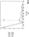
図4は、アナログ・ディジタル変換器によって変換された後の、時間にわたる、画像センサによって出力されたキャプチャ照明の強度のプロットである。出力照明データは画像データ内で混合され、図4では、両方が時間にわたってプロットされている。光の照明は各行がキャプチャされた各行の行平均を表す。Y軸はアナログ・ディジタル変換器の出力の単位であり、この実施形態では画像センサの出力の8ビットのアナログ・ディジタル変換で表された0から255までの整数である。キャプチャされた画像データ内の蛍光灯照明による照明強さの振動の周波数を決定するために、画像データはフーリエ変換処理される。これはさらに次の図6と共に説明される。
【0018】
画像データ内で振動している強さを有する照明による影響されたキャプチャをなくすためには、パルス波形の電力振幅のフーリエ変換が正弦関数(すなわち|Sin(X)/X|)の絶対値に似ており、特に、この関数はゼロを含むことに注意されたい。ゼロは照明フリッカに対応するので、フーリエ変換の電力振幅がゼロに等しい点での値に対応する値に積分時間が設定されている場合、照明フリッカをなくすことができる。したがって、画像が50Hzの照明の下でキャプチャされるか60Hzの照明の下でキャプチャされるかによって、積分時間を特定の値に設定し、照明の振動レベルによって引き起こされるフリッカ効果をなくすことができる。光源の振動周波数の決定を助けるときに、50Hzの光源または60Hzの光源のどちらから引き起こされる影響の強さが同じであるように、積分時間を選択することが必要である。
【0019】
図5から分かるように、60Hzの信号波形の振幅のプロットが、50Hz信号波形の振幅のプロットに等しいいくつかの場所がある。一実施形態では、積分時間は0.0132秒に設定されている。積分時間が50Hz周波数および60Hz周波数に対して同じ振幅という結果になる値に設定されている理由は、ある周波数の照明の存在を簡単に検出できるようにするためである。たとえば、積分時間が、50Hz信号の振幅が60Hz信号の振幅よりはるかに大きい0.017秒に設定されていた場合は、60Hz信号によって引き起こされた効果はゼロに非常に近いのでその効果を検出することは非常に難しくなる。表1は、光源の振動周波数を決定するために適した積分時間のサンプル・リストである。
【表1】

図4に関して上に論じられたように、キャプチャされた画像の振動する照明の効果が画像データ内に含まれている。照明効果を分離するために、高速フーリエ変換(FFT)関数が画像データに対して実行され、照明の振動があった場合にはその周波数を決定する。
【0021】
図6はFFTの後の図4に示されたデータのプロットであり、図4の画像データをキャプチャしている間の照明が、60Hz光源からのものであると仮定している。図6で分かるように、120Hzに現れる「スパイク」があり、60Hzの電力ライン源が検出されたことを照明データが示している。照明は、この場合は60Hzであるライン周波数の2倍で変動するので、スパイクは120Hzで現れることに注意されたい(すなわち、照明は60Hzサイクルの「正」の部分および「負」の部分の両方で行われている)。
【0022】
図7は、本発明の一実施形態によって構成された画像キャプチャおよび処理システムの構成図であり、フォトセンサ・アレイ100、バッファおよび処理ユニット102、アナログ・ディジタル(A/D)ユニット104、キャプチャ制御ユニット106、FFTユニット108、および検出器ユニット110をもつ。バッファおよび処理ユニット102、FFT108、および検出ユニット110がフリッカ検出器112を構成する。
【0023】
フォトセンサ・アレイ100はパイプライン式モードで動作し、すなわち、上記のように、フォトセンサ・アレイ100の各行が行ごとに積分されることを意味する。フォトセンサ・アレイ100の出力はA/Dユニット104に供給される。具体的にはフォトセンサ・アレイ100は、キャプチャ制御ユニット106によって送られた制御信号に基づいてキャプチャ電荷をA/Dユニット104に出力し、処理する。キャプチャ制御ユニット106はフリッカ検出器112によって制御される。具体的には、バッファおよび処理ユニット102がA/Dユニット104からキャプチャされた画像データを受信すると、必要な任意の処理を実行し、次いでその結果をFFTユニット108に送信する。FFTユニット108は次いで、バッファおよび処理ユニット102から受信された結果に対して作用し、次にその結果のデータを検出器ユニット110に送る。次いで検出器ユニット110は信号をキャプチャ制御ユニット106に出力し、カメラがその下で動作する照明条件を示す。上記のように、バッファおよび処理ユニット102、FFTユニット108、および検出器ユニット110はフリッカ検出器112を構成する。
【0024】
一実施形態では、バッファおよび処理ユニット102がA/Dユニット104からデータを受け取ると同時に、バッファおよび処理ユニット102は同じ情報を後処理および格納ユニット(図示せず)に提供する。後処理および格納ユニットは、圧縮または画像強化などのさらなる画像処理を行うためのユニットを含む場合もある。後処理および格納ユニット内の格納構成要素は、ディジタル・データを格納するのに適した任意の媒体でよい。一実施形態では、格納ユニットは磁気媒体などの非揮発性メモリである。しかし、揮発性メモリまたは非揮発性メモリのいずれでも、ディジタル・データを格納するために使用される任意の格納装置が適している。別の実施形態では、フリッカ検出器112によって提供される機能は、後処理および格納ユニットによって提供される機能と共に実施できる。さらに、フリッカ検出器112の機能は、処理および格納ユニットで提供される機能と共に、上記のように汎用プロセッサおよび格納ユニットを提供する汎用コンピュータによっても提供できることに注意されたい。このようにして、図7に示された処理および格納ユニットの実際の実施態様は、これらがハードウェアでもソフトウェアでも、種々のソリューション内に実装できる。
【0025】
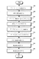
図8は本発明の動作の一実施形態の流れ図である。プロセスはステップ300で開始する。この中でキャプチャ制御ユニット106は特定のフレーム・レートでフォトセンサ・アレイ100を使用して1つまたは複数のフレームをキャプチャするように設定されている。最小のフレーム・レートは、取得されるべきデータ・サンプルの合計数による。サンプリング・レートおよびサンプルの合計数はサンプル数が少なすぎないように選択される。正確なサンプリング要件は、ナイキスト解像度が維持されることを前提として、ほとんど無限の範囲にわたって変化する可能性がある。一実施形態では、フレーム・レートは少なくとも120Hzを回復するように設定され、120Hzは任意の遭遇する可能性のある蛍光灯の光の周波数レートの2倍である(すなわち、遭遇する可能性のある最も高い供給電源ライン周波数である60Hzの2倍である)。これは、サンプル数が少なすぎることによるナイキスト効果を避けるためにキャプチャ周波数が十分に高くなければならないので、照明内の変動がキャプチャされることを確実にする。
【0026】
フォト・センサ・アレイ100内の各ラインは照明の1つの「サンプル」をキャプチャするので、サンプル数が少なすぎることは通常は問題ではない。たとえば、1秒に15フレームという典型的なフレーム・レートを仮定すると、フォト・センサ・アレイ100が16ラインだけの解像度を有している場合でも、十分なサンプルがあり、240Hzのナイキスト解像度を満足させ、120Hzを回復できる。
【0027】
ステップ302では、積分時間は約13.2ミリ秒に設定されている。上記のように、この積分時間は、60Hzの光源または50Hzの光源からの照明のキャプチャが同じ振幅とさせるように選択されている。動作は次にステップ304に進む。
【0028】
ステップ304では、1つまたは複数のフレームが、ステップ302でキャプチャ制御ユニット106によって設定された積分時間(すなわち、13.2ミリ秒)においてフォトセンサ・アレイ100によってキャプチャされる。具体的には、各行に関して使用される積分時間は13.2ミリ秒である。
【0029】
ステップ306では、フレームの各行ごとにキャプチャされた画像データは水平に平均化される。上記のように、行内の各ピクセルの画像データを平均することは、場面内に暗い被写体または明るい被写体を有する効果を減少し、蛍光灯によって引き起こされた任意の照明の変動はより簡単に検出される。たとえば、キャプチャされている画像が完全に白い絵であるなど、画像データ内で完全に均一である場合、照明の任意の変化は簡単に検出できる。平均しなければ、ランダムな列のピクセルを選択することは、フォトセンサ・アレイ100のどの列が選択されるかによって、予測できない結果を生み出す。結果として生じたデータは図4のデータと同様である。
【0030】
ステップ308では、複数のフレームがキャプチャされており、フレーム間のギャップがゼロに等しいと仮定すると(すなわち、フレームは休止なしで連続的にキャプチャされている)、水平に平均化された画像データは「縫い合わされ」、水平に平均化された画像データの連続したシリーズを形成する。動作は次いでステップ310に続く。
【0031】
ステップ310では、高速フーリエ変換(FFT)がFFTユニット108によって画像データに対して実行される。上記のように、ステップ308から水平に平均化された画像データに対してFFTを実行すると、結果はたとえば図6に示されたようになる(ライン周波数は60Hzである)。120Hzを解像する十分なデータがある限り、100Hzも解像可能であることに注意されたい。動作は次いでステップ312に続く。
【0032】
ステップ312では、100Hz値のFFTの値は120Hz値の値と比較される。ステップ314では、検出器ユニット110は60Hz値のための値(すなわち、ナイキスト解像度のために使用される120Hz値)、または50Hz値(すなわち、ナイキスト解像度のために使用される100Hz値)のどちらがより大きいかを決定する。一実施形態では、60Hz値および50Hz値の両方が互いの10%内であれば、カメラは白熱灯の下で動作していることが仮定される。動作は次いでブロック316に継続する。
【0033】
FFTの使用は計算の最適化であり、要件ではないことに注意されたい。別の実施形態では離散フーリエ変換も使用される。離散フーリエ変換を実行する利点は、離散フーリエ変換がFFTよりもより計算が複雑であるにもかかわらず、2のべき乗個の数の値(a power of two number of values)から成り立つデータ・セットを選択するように制限されず、特定の問題すなわち周波数スミアの問題を解決することができる。
【0034】
ディジタル時間領域から周波数領域への変換が実行される時、ナイキスト・サンプリング基準が満たされていない場合、入力データはエイリアスとなる。出力スペクトルにも同様な問題があり、ここではデータ・セット内の周波数は2つのディジタル周波数値の「間」であり、周波数エイリアシングが発生し、その結果生じるスペクトルは不鮮明になる。周波数スミアを避けるために、計算を追加するという犠牲を払って離散フーリエ変換が使用される場合がある。検出は最初の照明条件を決定するために1度だけ実行されればいいので、計算上より複雑なアルゴリズムを使用することは受け入れられる。選択肢は計算時間と識別精度とのトレードオフであるが、高速フーリエ変換の使用は要件ではない。
【0035】
ステップ316では、検出器ユニット110による、カメラが60Hzの下で動作しているか50Hzの下で動作しているか、または白熱灯様の条件の下で動作しているかの決定に基づいて、積分時間がそれに従って設定される。
【0036】
フリッカ周波数がステップ314で決定されると、検出器ユニット110は、一実施形態ではフリッカ周波数を表す信号を出力する。別の実施形態では、検出器ユニット110は白熱灯、50Hz照明システム、または60Hz照明システムが検出されたかどうかを知らせる信号を出力する。光源が非フリッカリング・ソースである場合、これは上記のステップ314で決定されているはずである。次いでキャプチャ制御ユニットは検出された周波数に関して適当な積分時間を決定する。
【0037】
ある構成では、検出器ユニット110は検出されたフリック周波数に基づいて正しい積分時間を決定する。次いで検出器ユニット110はキャプチャ制御ユニット106を制御して、決定されたフレーム・レートでキャプチャする。したがって、フレーム・レート・キャプチャの制御の実施態様はいくつかの方法で実行でき、特定の実施形態に限定されない。
【0038】
光源強度の振動の実際の周波数を出力する本発明は50Hzのシステムまたは60Hzのシステムのみでキャプチャされたビデオからフリッカ効果をなくすことに制限されない。たとえば、提供されている光源がユーザのコンピュータ・モニタだけなどのような非常に光が少ない状況において、システムが実際に検出された光の周波数を出力すればフリッカ効果をなくすことができる。これは、ほとんどのモニタが60Hzから開始するリフレッシュ・レートを有するためである。たとえば、場面が75Hzのリフレッシュ・レートを有するモニタで照明されている場合、カメラはビデオ・フレーム・キャプチャをモニタのリフレッシュ・レートに同期すべきである。
【0039】
本発明が種々の図を参照して具体的に記述されたが、図面は例示のみの目的であり、本発明の範囲を限定するものとして受け取られるべきではないことを理解されたい。本発明の精神および範囲から離れることなく、当業者によって本発明に多くの変更および修正を行うことができる。
【図面の簡単な説明】
【図1】 時間にわたって測定された放電灯からの光の強度のプロットである。
【図2】 パイプライン式画像センサを使用した、時間にわたる画像データのサンプリングを示す図である。
【図3】 特定のキャプチャされた画像に関して、時間にわたってキャプチャされた画像データの平均化された行のプロットである。
【図4】 時間にわたる、画像データを含む、キャプチャされた照明の強度のプロットである。
【図5】 異なる周波数の2つの光源に関する、積分時間とフリッカ振幅のプロットである。
【図6】 図4に示された信号のフーリエ変換後のプロットである。
【図7】 フリッカ検出器を含む本発明の一実施形態によって構成された画像キャプチャ・システムの図である。
【図8】 フリッカ検出器を含む画像キャプチャ・システムの動作の流れ図である。[0001]
(background)
(Field of Invention)
The present invention relates to the field of use of digital video capture. More particularly, the present invention relates to a method and apparatus for eliminating flicker effects from a discharge lamp during pipelined digital video capture.
[0002]
(Description of related technology)
Digital cameras are currently used in many applications, including both still image acquisition and video acquisition. A digital camera uses a sensor array consisting of a pattern made up of photodiodes (ie, photoelectric diodes or photosensors) to acquire an image. Each photodiode measures the amount of light received by the photodiode by storing a corresponding amount of charge in an embedded capacitor. The charge stored by each photodiode is then converted to a digital value by an analog-to-digital converter, converted and processed so that all digital values become a digital image after being reassembled into a particular array.
[0003]
Typically, the array of photosensors is exposed to the scene to be captured using either a mechanical shutter or an electronic shutter. Each mechanical or electronic shutter (1) causes light to enter the photosensor array, and (2) causes charge to accumulate in each photosensor in the array. The photosensor array can also capture charge for each row, or alternatively, the entire image can be captured (ie, the photosensor array is exposed to the light source at once). The processing of the charge accumulated on each photosensor is then performed in a row-by-row manner or in a pixel-by-pixel manner. Images captured in this row-by-line manner are called captured in a “pipeline” mode of operation. For video image capture applications, a series of frames (ie images) are captured in a similar manner as described above.
[0004]
As digital cameras have become a replacement for traditional film-based cameras, it has become possible to operate under a variety of lighting conditions. For example, a digital camera must be able to capture video of scenes illuminated by sunlight outdoors and video of scenes illuminated by incandescent or fluorescent lights indoors.
[0005]
However, due to the fact that when capturing a sequence of frames under an environment illuminated by a discharge lamp (eg a fluorescent lamp), the discharge lamp can change in intensity and color temperature as a function of time, Digital video will contain artifacts. Thus, a discharge lamp, such as a fluorescent lamp, does not provide a constant light intensity, but when measured and depicted in the drawing, it has an intensity similar to a full-wave rectified sine wave.
[0006]
FIG. 1 shows an example of the intensity of fluorescent lamp illumination that varies with time. In this figure, the Y axis represents the intensity of light sensed by the photodiode, and the X axis represents the passage of time. As can be seen from FIG. 1, the intensity of the light generated by the fluorescent lighting (and thus sensed by the photodiode) is periodic and resembles the absolute value of a sine wave. Since the change in intensity is a function of time and capture is also a function of time, the video stream captured with this illumination may contain a significant amount of variation in the quality of the captured video.
[0007]
The problem is also that some countries use a 60 Hz alternating current (AC) power system and another country uses a 50 Hz AC power system, so that changes in the intensity of fluorescent lighting are different in different parts of the world. Become more serious from the facts. For example, the United States uses an AC power system that vibrates at 60 Hz. Therefore, depending on the country in which the digital camera is used, it is necessary to adjust the frame capture rate so that the frame capture rate is a function of the operating cycle of power supply.
[0008]
One way to allow a digital camera to function under fluorescent lighting in different power systems is to have the user enter a code that specifies the country in which the digital camera is used. The camera then adjusts the frame capture rate according to the country's operating frequency. The camera maintains a list of the current operating systems, as well as a list of power systems that are functioning in that area. This method also requires the user to enter a code each time the user enters an area with a different power system. This method therefore requires the user to manually enter the user's current location.
[0009]
The second method is “aware” about where the camera is now in geography, and automatically enables the camera's internal system to be set accordingly, such as a global positioning system (GPS) The system is built into the camera itself. However, this method requires additional circuitry that adds power and cost requirements to the digital camera.
[0010]
Yet another method is to include circuitry that allows the user to automatically recognize the power system that the camera is currently operating by plugging the camera into the country's power system. For example, when the user arrives at a location or a new area, the digital camera circuit can register the operating cycle of the power system by simply plugging the camera into a wall outlet. However, different regions of the world usually have differently configured wall sockets and connectors on these sockets, so users can be dozens or hundreds to plug the digital camera into the power system reliably This method is also not recommended because you have to carry a collection of adapters.
[0011]
It would be desirable to have a system that eliminates the effects of using fluorescent lighting without requiring user intervention in the camera itself, or increased cost and power requirements.
[0012]
(Overview)
Disclosed is a method having a first step of setting a first frame rate. The capture integration period is then set to a first integration period, and a set of frames is captured under an illumination source having a first frequency. Thereafter, a first frequency of illumination is determined. Also disclosed is an apparatus that performs the above method and has an image sensor and a capture control unit coupled to the image sensor.
[0013]
(Detailed description of the invention)
The present invention provides a method and apparatus for reducing flicker effects from discharge lamps in a captured video stream. For purposes of explanation, specific embodiments are shown in order to provide a thorough understanding of the present invention. However, one of ordinary skill in the art will appreciate from reading this disclosure that the invention can be practiced without these details. Furthermore, although the present invention has been described through the use of CMOS image sensors, most if not all aspects of the present invention apply to general image sensors. In addition, well-known elements, devices, process steps, etc. have not been shown in detail in order to avoid obscuring the present invention.
[0014]
Because of the applied AC voltage, the intensity and color value output from the fluorescent light varies in a sinusoidal and thus periodic manner, the present invention uses an image sensor to sample the entire illumination and the system is 50 Hz. Detect whether operating at 60 Hz or incandescent lamp conditions. Integration is then performed by the image sensor under different restrictions based on the detected optical frequency. This timing allows the photosensor array to capture each frame at approximately the same time as the light intensity oscillation cycle received from the fluorescent lamp.
[0015]
FIG. 2 is a diagram of sampling image data over time using a pipelined image sensor. Frame capture begins at
[0016]
FIG. 3 is a plot of captured image data for each row averaged over time for a particular captured image (ie, the pixel values for each row are averaged). As will be discussed next, the image data is averaged for each row to mitigate the effects of selecting a particular column of pixel data to analyze. For example, if the pixel values in the last column on the right side of the image are selected and analyzed, the pixel data column will produce very different results than if taken from the center of the image. By averaging the image data for each row, the actual change in value due to the “picture” contained in the image has less effect on the actual data used for the analysis of the illumination of the image.
[0017]
FIG. 4 is a plot of the intensity of the capture illumination output by the image sensor over time after being converted by the analog to digital converter. The output illumination data is mixed in the image data, and in FIG. 4, both are plotted over time. The light illumination represents the row average of each row that was captured. The Y axis is a unit of the output of the analog / digital converter, and in this embodiment, is an integer from 0 to 255 expressed by 8-bit analog / digital conversion of the output of the image sensor. The image data is Fourier transformed to determine the frequency of illumination intensity oscillations due to fluorescent lighting within the captured image data. This is further explained in conjunction with the next FIG.
[0018]
In order to eliminate the affected capture by illumination having intensity oscillating in the image data, the Fourier transform of the power amplitude of the pulse waveform is converted to the absolute value of the sine function (ie | Sin (X) / X |). Note that it is similar and in particular this function contains zeros. Since zero corresponds to illumination flicker, illumination flicker can be eliminated if the integration time is set to a value corresponding to the value at the point where the power amplitude of the Fourier transform is equal to zero. Thus, depending on whether the image is captured under 50 Hz illumination or 60 Hz illumination, the integration time can be set to a specific value to eliminate the flicker effect caused by the illumination vibration level. . In helping to determine the vibration frequency of the light source, it is necessary to select the integration time so that the intensity of the effects caused by either the 50 Hz light source or the 60 Hz light source is the same.
[0019]
As can be seen from FIG. 5, there are several places where the 60 Hz signal waveform amplitude plot is equal to the 50 Hz signal waveform amplitude plot. In one embodiment, the integration time is set to 0.0132 seconds. The reason why the integration time is set to a value that results in the same amplitude for the 50 Hz frequency and the 60 Hz frequency is to make it possible to easily detect the presence of illumination at a certain frequency. For example, if the integration time was set to 0.017 seconds, where the amplitude of the 50 Hz signal is much larger than the amplitude of the 60 Hz signal, the effect caused by the 60 Hz signal is very close to zero and the effect is detected. It becomes very difficult. Table 1 is a sample list of integration times suitable for determining the vibration frequency of the light source.
[Table 1]
As discussed above with respect to FIG. 4, the effect of oscillating illumination of the captured image is included in the image data. In order to separate the lighting effects, a Fast Fourier Transform (FFT) function is performed on the image data to determine the frequency of any illumination vibrations.
[0021]
FIG. 6 is a plot of the data shown in FIG. 4 after FFT, assuming that the illumination while capturing the image data of FIG. 4 is from a 60 Hz light source. As can be seen in FIG. 6, there is a “spike” appearing at 120 Hz, and the illumination data indicates that a 60 Hz power line source has been detected. Note that the spikes appear at 120 Hz because the illumination varies at twice the line frequency, which in this case is 60 Hz (ie, the illumination is both a “positive” and a “negative” portion of the 60 Hz cycle. Is done in).
[0022]
FIG. 7 is a block diagram of an image capture and processing system configured in accordance with one embodiment of the present invention, including a
[0023]
[0024]
In one embodiment, at the same time that the buffer and
[0025]
FIG. 8 is a flowchart of one embodiment of the operation of the present invention. The process begins at
[0026]
Since each line in the
[0027]
In
[0028]
At
[0029]
In
[0030]
In
[0031]
In
[0032]
In
[0033]
Note that the use of FFT is a computational optimization and not a requirement. In another embodiment, a discrete Fourier transform is also used. The advantage of performing a discrete Fourier transform is that a data set consisting of a power of two number of values, even though the discrete Fourier transform is more computationally complex than FFT. Without being restricted to choose, a specific problem, namely the frequency smear problem can be solved.
[0034]
When a digital time domain to frequency domain transformation is performed, the input data is aliased if the Nyquist sampling criteria are not met. There is a similar problem with the output spectrum, where the frequency in the data set is “between” two digital frequency values, frequency aliasing occurs, and the resulting spectrum is blurred. To avoid frequency smear, a discrete Fourier transform may be used at the expense of additional computation. Since the detection need only be performed once to determine the initial lighting conditions, it is acceptable to use a computationally more complex algorithm. The choice is a trade-off between computation time and identification accuracy, but the use of a fast Fourier transform is not a requirement.
[0035]
In
[0036]
Once the flicker frequency is determined at
[0037]
In one configuration,
[0038]
The present invention of outputting the actual frequency of the light source intensity vibration is not limited to eliminating the flicker effect from video captured with a 50 Hz system or only a 60 Hz system. For example, the flicker effect can be eliminated if the system outputs the frequency of the actually detected light in situations where the light source provided is very low in light, such as only the user's computer monitor. This is because most monitors have a refresh rate starting from 60 Hz. For example, if the scene is illuminated by a monitor having a 75 Hz refresh rate, the camera should synchronize the video frame capture to the monitor refresh rate.
[0039]
Although the invention has been specifically described with reference to various figures, it should be understood that the drawings are for illustrative purposes only and should not be taken as limiting the scope of the invention. Many changes and modifications may be made to the invention by those skilled in the art without departing from the spirit and scope of the invention.
[Brief description of the drawings]
FIG. 1 is a plot of the intensity of light from a discharge lamp measured over time.
FIG. 2 illustrates sampling of image data over time using a pipelined image sensor.
FIG. 3 is an averaged row plot of image data captured over time for a particular captured image.
FIG. 4 is a plot of captured illumination intensity over time, including image data.
FIG. 5 is a plot of integration time and flicker amplitude for two light sources of different frequencies.
6 is a plot after Fourier transform of the signal shown in FIG.
FIG. 7 is a diagram of an image capture system configured in accordance with one embodiment of the present invention that includes a flicker detector.
FIG. 8 is a flowchart of the operation of an image capture system including a flicker detector.
Claims (3)
Applications Claiming Priority (3)
| Application Number | Priority Date | Filing Date | Title |
|---|---|---|---|
| US09/123,496 US6501518B2 (en) | 1998-07-28 | 1998-07-28 | Method and apparatus for reducing flicker effects from discharge lamps during pipelined digital video capture |
| US09/123,496 | 1998-07-28 | ||
| PCT/US1999/014423 WO2000007363A1 (en) | 1998-07-28 | 1999-06-24 | Method and apparatus for reducing flicker effects from discharge lamps during pipelined digital video capture |
Publications (3)
| Publication Number | Publication Date |
|---|---|
| JP2002521974A JP2002521974A (en) | 2002-07-16 |
| JP2002521974A5 JP2002521974A5 (en) | 2006-08-17 |
| JP4195197B2 true JP4195197B2 (en) | 2008-12-10 |
Family
ID=22409005
Family Applications (1)
| Application Number | Title | Priority Date | Filing Date |
|---|---|---|---|
| JP2000563062A Expired - Fee Related JP4195197B2 (en) | 1998-07-28 | 1999-06-24 | Method and apparatus for reducing flicker effects from discharge lamps during pipelined digital video capture |
Country Status (10)
| Country | Link |
|---|---|
| US (2) | US6501518B2 (en) |
| JP (1) | JP4195197B2 (en) |
| KR (1) | KR100381532B1 (en) |
| CN (1) | CN1146225C (en) |
| AU (1) | AU4832599A (en) |
| DE (1) | DE19983408B4 (en) |
| GB (1) | GB2354663B (en) |
| MY (1) | MY124395A (en) |
| TW (1) | TW403852B (en) |
| WO (1) | WO2000007363A1 (en) |
Families Citing this family (41)
| Publication number | Priority date | Publication date | Assignee | Title |
|---|---|---|---|---|
| US6421097B1 (en) * | 1998-07-31 | 2002-07-16 | Intel Corporation | Method and apparatus for reducing flicker in a video image sequence |
| JP3370979B2 (en) * | 2000-09-08 | 2003-01-27 | 三菱電機株式会社 | Imaging apparatus and automatic level adjustment method |
| JP4608766B2 (en) * | 2000-11-27 | 2011-01-12 | ソニー株式会社 | Method for driving solid-state imaging device and camera |
| JP4416959B2 (en) | 2001-04-26 | 2010-02-17 | 富士通マイクロエレクトロニクス株式会社 | Flicker noise reduction method for XY address type solid-state imaging device |
| US7187405B2 (en) * | 2001-10-02 | 2007-03-06 | Avago Technologies General Ip (Singapore) Pte. Ltd. | Automatic flicker frequency detection device and method |
| US7239345B1 (en) * | 2001-10-12 | 2007-07-03 | Worldscape, Inc. | Camera arrangements with backlighting detection and methods of using same |
| US20030090587A1 (en) * | 2001-10-30 | 2003-05-15 | Hofer Gregory V. | Method and apparatus for auto-focus control in the presence of artificial illumination |
| US7009642B2 (en) * | 2001-10-30 | 2006-03-07 | Hewlett-Packard Development Company, L.P. | Method and apparatus for detecting the presence of artificial illumination in a scene |
| US6989860B2 (en) * | 2001-10-30 | 2006-01-24 | Hewlett-Packard Development Company, L.P. | Method and apparatus for auto-exposure control in the presence of artificial illumination |
| JP3823314B2 (en) * | 2001-12-18 | 2006-09-20 | ソニー株式会社 | Imaging signal processing apparatus and flicker detection method |
| JP2003198932A (en) * | 2001-12-27 | 2003-07-11 | Sharp Corp | Flicker correction device, flicker correction method, and recording medium with flicker correction program recorded |
| JP4337353B2 (en) * | 2002-03-25 | 2009-09-30 | セイコーエプソン株式会社 | Flicker detection device, flicker correction device, imaging device, flicker detection program, and flicker correction program |
| JP2004112742A (en) * | 2002-07-25 | 2004-04-08 | Fujitsu Ltd | Image sensor with image distortion suppressed |
| KR100460755B1 (en) * | 2002-10-10 | 2004-12-14 | 매그나칩 반도체 유한회사 | Pixel array for image sensor and image sensor having the same and auto removal method for flicker noise of image sensor |
| US7126639B2 (en) * | 2002-10-29 | 2006-10-24 | Hewlett-Packard Development Company, L.P. | Digital camera printing user interface responsive to location |
| SE525331C2 (en) * | 2002-12-23 | 2005-02-01 | Unipower Ab | Measurement method for determining direction to flicker source |
| JP3826904B2 (en) | 2003-07-08 | 2006-09-27 | ソニー株式会社 | Imaging apparatus and flicker reduction method |
| JP4106554B2 (en) | 2003-09-08 | 2008-06-25 | ソニー株式会社 | Imaging environment determination method and imaging apparatus |
| US20050237394A1 (en) * | 2004-04-21 | 2005-10-27 | Behnam Katiblan | Flicker detection for image sensing devices |
| US7538799B2 (en) * | 2005-01-14 | 2009-05-26 | Freescale Semiconductor, Inc. | System and method for flicker detection in digital imaging |
| US7683948B2 (en) * | 2005-03-31 | 2010-03-23 | Freescale Semiconductor, Inc. | System and method for bad pixel replacement in image processing |
| JP4377840B2 (en) * | 2005-03-31 | 2009-12-02 | イーストマン コダック カンパニー | Digital camera |
| JP4756960B2 (en) * | 2005-09-02 | 2011-08-24 | キヤノン株式会社 | Imaging apparatus, control method therefor, computer program, and storage medium |
| US7777787B2 (en) * | 2005-10-17 | 2010-08-17 | Nokia Corporation | Preventing flicker effects in video electronic devices |
| US8068148B2 (en) * | 2006-01-05 | 2011-11-29 | Qualcomm Incorporated | Automatic flicker correction in an image capture device |
| TWI306572B (en) * | 2006-02-15 | 2009-02-21 | Pixart Imaging Inc | Light pointing device and light tracking receiver having function selection key and system using the same |
| TWI311883B (en) * | 2006-05-10 | 2009-07-01 | Novatek Microelectronics Corp | Flicker frequency detection method and device |
| US7667740B2 (en) * | 2006-07-28 | 2010-02-23 | Hewlett-Packard Development Company, L.P. | Elimination of modulated light effects in rolling shutter CMOS sensor images |
| US7847834B2 (en) * | 2007-11-19 | 2010-12-07 | Omnivision Technologies, Inc. | Light source frequency detection circuit using bipolar transistor |
| KR101164193B1 (en) * | 2008-12-22 | 2012-07-11 | 한국전자통신연구원 | System and method for distinguishing and detecting multiple infrared signal coordinates |
| WO2011059502A1 (en) * | 2009-11-13 | 2011-05-19 | Steven Donald Edelson | Monitoring and camera system and method |
| US9088727B2 (en) * | 2011-04-06 | 2015-07-21 | Pelco, Inc. | Spatially-varying flicker detection |
| CN103108132B (en) * | 2011-11-15 | 2016-06-15 | 慧荣科技股份有限公司 | Anti-flicker camera device and recording method |
| JP5814865B2 (en) * | 2012-06-20 | 2015-11-17 | 株式会社 日立産業制御ソリューションズ | Imaging device |
| US9106839B2 (en) * | 2013-04-05 | 2015-08-11 | Google Inc. | Automatic location-based camera frame rate settings |
| FR3009469B1 (en) * | 2013-07-31 | 2016-11-25 | Morpho | METHOD OF SYNCHRONIZING MULTIPLE CAMERAS OF A SHOOTING SYSTEM, IN PARTICULAR A STEREOSCOPIC VIEWING SYSTEM AND VIEWING SYSTEM FOR IMPLEMENTING SAID METHOD |
| EP2950523A1 (en) * | 2014-05-28 | 2015-12-02 | Thomson Licensing | Method of estimating flicker on recorded video by camcorder |
| CN104378628B (en) * | 2014-11-28 | 2018-04-24 | 广东中星电子有限公司 | A kind of method of detection image flicker striped |
| DE102020202400A1 (en) * | 2020-02-25 | 2021-08-26 | OSRAM Opto Semiconductors Gesellschaft mit beschränkter Haftung | OPTOELECTRONIC SENSOR DEVICE, DETECTOR AND ELECTRONIC DEVICE, AND A METHOD FOR OPERATING SUCH SENSOR DEVICE OR. SUCH A DETECTOR |
| KR20220048090A (en) * | 2020-10-12 | 2022-04-19 | 삼성전자주식회사 | Method of testing image sensor using frequency domain and test system performing the same |
| CN112887629B (en) * | 2021-01-27 | 2022-08-23 | 维沃移动通信有限公司 | Frequency detection method, frequency detection device, electronic equipment and storage medium |
Family Cites Families (14)
| Publication number | Priority date | Publication date | Assignee | Title |
|---|---|---|---|---|
| US4827119A (en) * | 1988-01-28 | 1989-05-02 | Eastman Kodak Company | Illuminant discriminator |
| KR930005751B1 (en) * | 1990-07-04 | 1993-06-24 | 삼성전자 주식회사 | Flicker prevention circuit of ccd camera |
| JPH04237271A (en) * | 1991-01-21 | 1992-08-25 | Fuji Photo Film Co Ltd | Image pickup device |
| JP2995887B2 (en) | 1991-03-27 | 1999-12-27 | 松下電器産業株式会社 | Flicker correction circuit |
| JP3188978B2 (en) | 1991-09-04 | 2001-07-16 | 株式会社ニコン | Camera photometer |
| JP3170588B2 (en) * | 1992-10-08 | 2001-05-28 | 日本オプネクスト株式会社 | Optical receiver test method |
| JPH06209427A (en) | 1993-01-11 | 1994-07-26 | Matsushita Electric Ind Co Ltd | Solid-state image pickup device |
| KR0148450B1 (en) * | 1994-04-08 | 1998-11-16 | 가나이 쯔또무 | Image pick-up device & method for controlling the same |
| US5548398A (en) * | 1994-11-22 | 1996-08-20 | Eastman Kodak Company | Illuminant discriminator providing detection of high efficiency illumination |
| AU6298396A (en) * | 1995-06-26 | 1997-01-30 | Phase One Denmark A/S | Digital camera image recording method and system |
| JPH0965198A (en) | 1995-08-29 | 1997-03-07 | Rhythm Watch Co Ltd | Image pickup device |
| US5925875A (en) * | 1996-04-26 | 1999-07-20 | Lockheed Martin Ir Imaging Systems | Apparatus and method for compensating for fixed pattern noise in planar arrays |
| KR970072970A (en) * | 1996-04-30 | 1997-11-07 | 이대원 | High-sensitivity camera using frame memory |
| JPH10136267A (en) | 1996-09-05 | 1998-05-22 | Seiko Epson Corp | Image input method/device |
-
1998
- 1998-07-28 US US09/123,496 patent/US6501518B2/en not_active Expired - Fee Related
-
1999
- 1999-06-24 JP JP2000563062A patent/JP4195197B2/en not_active Expired - Fee Related
- 1999-06-24 AU AU48325/99A patent/AU4832599A/en not_active Abandoned
- 1999-06-24 CN CNB998089257A patent/CN1146225C/en not_active Expired - Fee Related
- 1999-06-24 WO PCT/US1999/014423 patent/WO2000007363A1/en active IP Right Grant
- 1999-06-24 KR KR10-2001-7001151A patent/KR100381532B1/en not_active IP Right Cessation
- 1999-06-24 DE DE19983408T patent/DE19983408B4/en not_active Expired - Fee Related
- 1999-06-24 GB GB0101335A patent/GB2354663B/en not_active Expired - Fee Related
- 1999-06-28 TW TW088110873A patent/TW403852B/en not_active IP Right Cessation
- 1999-06-29 MY MYPI99002718A patent/MY124395A/en unknown
-
2002
- 2002-12-20 US US10/324,891 patent/US6771305B2/en not_active Expired - Lifetime
Also Published As
| Publication number | Publication date |
|---|---|
| US6771305B2 (en) | 2004-08-03 |
| JP2002521974A (en) | 2002-07-16 |
| DE19983408B4 (en) | 2007-01-18 |
| AU4832599A (en) | 2000-02-21 |
| GB2354663A (en) | 2001-03-28 |
| US20030090566A1 (en) | 2003-05-15 |
| US20020131491A1 (en) | 2002-09-19 |
| WO2000007363A1 (en) | 2000-02-10 |
| DE19983408T1 (en) | 2001-06-28 |
| KR20010072073A (en) | 2001-07-31 |
| TW403852B (en) | 2000-09-01 |
| GB2354663B (en) | 2002-10-23 |
| GB0101335D0 (en) | 2001-03-07 |
| KR100381532B1 (en) | 2003-04-26 |
| CN1146225C (en) | 2004-04-14 |
| US6501518B2 (en) | 2002-12-31 |
| CN1315110A (en) | 2001-09-26 |
| MY124395A (en) | 2006-06-30 |
Similar Documents
| Publication | Publication Date | Title |
|---|---|---|
| JP4195197B2 (en) | Method and apparatus for reducing flicker effects from discharge lamps during pipelined digital video capture | |
| US6295085B1 (en) | Method and apparatus for eliminating flicker effects from discharge lamps during digital video capture | |
| JP4856765B2 (en) | Imaging apparatus and flicker detection method | |
| JP4539449B2 (en) | Image processing apparatus and imaging apparatus | |
| JP4948090B2 (en) | Imaging apparatus and drive control method | |
| KR20060129954A (en) | Image-processing apparatus and image-pickup apparatus | |
| US20070146501A1 (en) | Image pickup apparatus | |
| US8711245B2 (en) | Methods and systems for flicker correction | |
| WO2010058567A1 (en) | Flicker reduction device, integrated circuit, and flicker reduction method | |
| US20120236175A1 (en) | Methods and Systems for Flicker Correction | |
| US6519002B1 (en) | Method and apparatus to minimize flicker effects from a discharge light source during digital video capture | |
| JP2009017213A (en) | Imaging apparatus | |
| JP2000023040A (en) | Solid-state image pickup device and system on-chip solid- state image pickup device | |
| JP2006319831A (en) | Image processor and image pickup device | |
| JPS63308484A (en) | Solid-state image pickup device | |
| JP2016034110A (en) | Image pickup device, control method of the same, program and storage medium | |
| CN111131667B (en) | Image pickup apparatus that performs flicker detection, control method therefor, and storage medium | |
| JP5088361B2 (en) | Image processing apparatus and imaging apparatus | |
| JP2009017167A (en) | Image processor, image processing method and imaging device | |
| JP2007158964A (en) | Image processing apparatus and imaging device | |
| US20050103979A1 (en) | Temporal source analysis using array detectors | |
| KR20040095249A (en) | Imager and stripe noise removing method | |
| US20050195289A1 (en) | Solid-state area image sensor readout methods for illuminat discrimination and automatic white balance in digital cameras | |
| JP2003244555A (en) | Imaging apparatus and method | |
| JP2012134677A (en) | Imaging apparatus and imaging method |
Legal Events
| Date | Code | Title | Description |
|---|---|---|---|
| A521 | Request for written amendment filed |
Free format text: JAPANESE INTERMEDIATE CODE: A523 Effective date: 20060620 |
|
| A621 | Written request for application examination |
Free format text: JAPANESE INTERMEDIATE CODE: A621 Effective date: 20060620 |
|
| A977 | Report on retrieval |
Free format text: JAPANESE INTERMEDIATE CODE: A971007 Effective date: 20080811 |
|
| TRDD | Decision of grant or rejection written | ||
| A01 | Written decision to grant a patent or to grant a registration (utility model) |
Free format text: JAPANESE INTERMEDIATE CODE: A01 Effective date: 20080826 |
|
| A01 | Written decision to grant a patent or to grant a registration (utility model) |
Free format text: JAPANESE INTERMEDIATE CODE: A01 |
|
| A61 | First payment of annual fees (during grant procedure) |
Free format text: JAPANESE INTERMEDIATE CODE: A61 Effective date: 20080925 |
|
| R150 | Certificate of patent or registration of utility model |
Free format text: JAPANESE INTERMEDIATE CODE: R150 |
|
| FPAY | Renewal fee payment (event date is renewal date of database) |
Free format text: PAYMENT UNTIL: 20111003 Year of fee payment: 3 |
|
| FPAY | Renewal fee payment (event date is renewal date of database) |
Free format text: PAYMENT UNTIL: 20121003 Year of fee payment: 4 |
|
| FPAY | Renewal fee payment (event date is renewal date of database) |
Free format text: PAYMENT UNTIL: 20131003 Year of fee payment: 5 |
|
| R250 | Receipt of annual fees |
Free format text: JAPANESE INTERMEDIATE CODE: R250 |
|
| R250 | Receipt of annual fees |
Free format text: JAPANESE INTERMEDIATE CODE: R250 |
|
| R250 | Receipt of annual fees |
Free format text: JAPANESE INTERMEDIATE CODE: R250 |
|
| R250 | Receipt of annual fees |
Free format text: JAPANESE INTERMEDIATE CODE: R250 |
|
| R250 | Receipt of annual fees |
Free format text: JAPANESE INTERMEDIATE CODE: R250 |
|
| LAPS | Cancellation because of no payment of annual fees |