JP4189501B2 - Game machine - Google Patents
Game machine Download PDFInfo
- Publication number
- JP4189501B2 JP4189501B2 JP2006137274A JP2006137274A JP4189501B2 JP 4189501 B2 JP4189501 B2 JP 4189501B2 JP 2006137274 A JP2006137274 A JP 2006137274A JP 2006137274 A JP2006137274 A JP 2006137274A JP 4189501 B2 JP4189501 B2 JP 4189501B2
- Authority
- JP
- Japan
- Prior art keywords
- control board
- symbol
- main control
- code
- command
- Prior art date
- Legal status (The legal status is an assumption and is not a legal conclusion. Google has not performed a legal analysis and makes no representation as to the accuracy of the status listed.)
- Expired - Lifetime
Links
Images


Description
本発明は遊技機に関し、詳しくはゲームの進行及び内容を司る主制御基板とゲームの進行又は内容に対応した画像を表示制御する画像制御基板との通信の構成に係わる。 The present invention relates to a gaming machine, and more particularly to a communication configuration between a main control board that controls the progress and contents of a game and an image control board that controls display of an image corresponding to the progress or contents of the game.
遊技機、例えばパチンコ遊技機においては、発射された遊技球が始動口に入賞又は通過口を通過すると画面上で図柄を所定時間変動表示した後に静止表示し(停止表示)、この静止表示した図柄が予め定められた所定の図柄の組み合わせであればゲーム内容を遊技者に有利な状態としている。
遊技者に有利な状態とする予め定められた図柄の組み合わせを表示するか否かは、遊技球が始動口に入賞又は通過口を通過したタイミングに起因して選択される乱数値の値によって決定され、選択された乱数値が予め定められた値と一致すれば画面上に、例えば「777」又は「333」等の所定の図柄の組み合わせを表示し遊技者に有利なゲーム内容となったことを報知すると共に、所謂「大当り」と称して大入賞口等を所定時間開放して遊技者に大量の遊技球を賞球として払い出している。前記選択される乱数値は、一般的にはハード割込み等の微小時間毎に+1(インクリメント)して所定範囲の整数値を繰り返し作成するカウンタとして構成され、遊技球が始動口に入賞するタイミングが予測できないことから乱数として機能する。
パチンコ遊技機では、前記乱数値の選択及び乱数値の判定又は大入賞口の開放等のゲームの進行及び内容を「主制御基板」と称する制御基板(以下、単に「主制御基板」と呼ぶ。)で司り、画面上に所定の図柄の組み合わせ表示を行う等の画像制御処理は画像制御基板(「図柄制御基板」とも言う。)で実行している。
主制御基板と画像制御基板との通信は、従来は所謂「オフセット方式」と呼ばれる手段で実行されていた。
In a gaming machine, for example, a pachinko gaming machine, when a launched game ball wins a winning opening or passes through a passing opening, the symbols are displayed on the screen for a predetermined time and then displayed statically (stop display). If is a combination of predetermined symbols, the game content is advantageous to the player.
Whether or not to display a predetermined symbol combination that is advantageous to the player is determined by the value of the random value selected based on the timing at which the game ball wins the winning opening or passes the passing opening If the selected random number value matches the predetermined value, a predetermined combination of symbols such as “777” or “333” is displayed on the screen, and the game content is advantageous to the player. And a so-called “big hit” is opened for a predetermined time, and a large number of game balls are paid out to the player as prize balls. The selected random value is generally configured as a counter that repeatedly creates an integer value in a predetermined range by incrementing +1 (incrementing) every minute time such as a hard interrupt, and the timing at which a game ball wins a start opening is determined. It functions as a random number because it cannot be predicted.
In the pachinko gaming machine, the progress and contents of the game such as selection of the random number value, determination of the random number value, or opening of the prize winning opening are referred to as a “main control board” (hereinafter simply referred to as “main control board”). ), And image control processing such as displaying a predetermined combination of symbols on the screen is executed by an image control board (also referred to as “design control board”).
Conventionally, communication between the main control board and the image control board has been executed by a so-called “offset method”.
このオフセット方式では、主制御基板から画像制御基板に対して、図柄の種類及び該図柄の表示位置に対応したデータを所定時間、例えば前記ハード割込み毎に送信し1秒間に所定駒数の画像を表示するよう制御していた。
しかしながら、ハード割り込み毎又はハード割り込みに対応した時間毎にデータを送信することは、前記乱数値のインクリメントのタイミングを主制御基板以外の外部に知られることになる。このことを不正に利用して強制的に大当りを発生させる虞も考えられないこともなかった。
また、近年、画像制御の技術の発達によることと遊技者に一層の娯楽感を提供することを目的として、画面上での表示制御に種々の趣のある制御がなされている。例えば、大当りの期待感を抱かせるために図柄が変動中にキャラクタを突然出現させたり、背景画面を変化させたり、あるいは図柄の変動表示態様に所謂リーチ動作やトリック動作を盛り込むこと等の制御がなされている。これらの制御も主制御基板からの指示により実行されるが、これらの指示を頻繁に主制御基板で行うことは主制御基板の処理の負担が大きいという課題、画像制御基板にしても主制御基板からの頻繁の指示により制御の自由度が損なわれるという課題等が発生していた。
そこで、前記不正の虞を払拭することと画像制御基板の自由度を高めるために、次に述べる所謂「インテリジェント化」と称される発明が為された。
In this offset method, data corresponding to the symbol type and symbol display position is transmitted from the main control board to the image control board for a predetermined time, for example, at each hardware interrupt, and a predetermined number of frames are transmitted per second. It was controlled to display.
However, sending data every hard interrupt or every time corresponding to a hard interrupt makes the timing for incrementing the random number value known outside the main control board. There was no possibility that this would be illegally used to forcibly generate a big hit.
In recent years, various on-screen display controls have been performed for the purpose of developing image control technology and providing players with a more entertaining feeling. For example, in order to have a big hit expectation, a character suddenly appears while the design is changing, a background screen is changed, or a so-called reach operation or trick operation is incorporated in the change display mode of the design. Has been made. These controls are also executed according to instructions from the main control board. However, if these instructions are frequently performed on the main control board, there is a problem that the processing load of the main control board is heavy. There has been a problem that the degree of freedom of control is impaired by frequent instructions from.
Therefore, in order to eliminate the possibility of fraud and to increase the degree of freedom of the image control board, an invention called “intelligentization” described below has been made.
インテリジェント化と称される発明を採用した遊技機では、画像の変化する時点で主制御基板から画像制御基板にデータが送信される。即ち、変動表示される図柄の変動開始時、変動速度の変化時、変動の静止時、またこれらの表示される図柄に対応して画面上に表示される背景画面及びキャラクタが異なる種類の背景画面となる変化時又は異なる種類のキャラクタが表示される時点、等の時点に主制御基板から画像制御基板に画像の変化を実行するようデータが送信され変動を指示するのである。
このインテリジェント化を採用した遊技機は、主制御基板から画像制御基板に送信するタイミングは、前記乱数値のインクリメントのタイミングと異なることから不正の発生を未然に防止するという極めて優れた効果を有している。
In a gaming machine adopting an invention called intelligentization, data is transmitted from the main control board to the image control board when the image changes. That is, at the start of fluctuation of the symbol that is displayed in a variable manner, when the fluctuation speed changes, when the fluctuation is stationary, and the background screen displayed on the screen corresponding to the displayed symbol and the background screen of a different character type Data is transmitted from the main control board to the image control board at a time such as when a different character is displayed or when a different type of character is displayed, and the change is instructed.
The gaming machine adopting this intelligent system has an extremely excellent effect of preventing the occurrence of fraud since the timing of transmission from the main control board to the image control board is different from the timing of incrementing the random number value. ing.
しかしながら、前述したインテリジェント化を採用した遊技機においても、主制御基板は画像の変化時点毎に画像制御基板に画像を構成する図柄、背景又はキャラクタ等の変化を指示するデータを送信する必要があり、各種制御を実行する主制御基板の負担はまだ大きなものがある。
一方、画像制御基板においても主制御基板から画像の変化時点毎に指示される構成には変わりはなく、画像制御基板が独自に判断して各種の画像処理を実行するという自由度は依然として低いのが実状である。
本発明は、これらの課題を好適に解決し、主制御基板が画像制御以外の各種制御を一層緻密に実行できることを可能とし、画像制御基板においては主制御基板からの自由度を大きくして一層興趣ある画像を表現することを可能とし遊技者に娯楽感溢れる遊技機を提供することを目的とする。
However, even in the gaming machine adopting the above-described intelligentization, the main control board needs to transmit data instructing the image control board to change the design, background, character, or the like at every image change time point. The burden on the main control board that executes various controls is still large.
On the other hand, in the image control board, the configuration instructed from the main control board every time the image changes is not changed, and the degree of freedom that the image control board makes an independent determination and executes various image processes is still low. Is real.
The present invention suitably solves these problems and enables the main control board to perform various controls other than image control more precisely. In the image control board, the degree of freedom from the main control board is increased to further increase the degree of freedom. It is an object to provide an amusement machine full of amusement feeling that can express an interesting image.
前記課題を解決するため請求項1に記載の遊技機は、
遊技盤面上に発射された遊技球が特定の入賞口に入賞又は特定の通過口を通過するタイミングに起因して遊技者に有利なゲーム内容とするか否かを決定する主制御基板と、
該主制御基板により遊技者に有利なゲーム内容とするか否かを決定する毎に画面上の複数の図柄を変動表示した後、遊技者に有利なゲーム内容であるか否かを示す図柄の組み合わせの画像で静止表示するよう制御する図柄制御基板と、
を含む遊技機において、
前記主制御基板は、前記図柄の変動表示における変動の態様を指示する変動パターンをコード化したコマンドコードを送信する構成を有し、一方、図柄制御基板では、受信したコマンドコードに従って画面上に図柄を表示するよう構成し、
前記主制御基板は、
前記コマンドコードとして、前記図柄の最初の図柄が変動開始してから最後の図柄が停止するまでの1回の変動表示について設定された変動時間及び大当りか否かの情報を示す予め複数種類以上パターン化した変動パターンを選択するスタートコードを有し、
前記主制御基板のCPUは、前記タイミングに起因していずれか1つのスタートコードを選択し、前記選択されたスタートコードを前記図柄制御基板に送信し、
前記主制御基板のCPUは、遊技者が遊技を実行していないと判断したときには、客待ちデモコマンドを前記図柄制御基板に送信し、
一方、前記図柄制御基板のCPUは、
前記1つのスタートコードを受信し、受信したスタートコードの大当たりか否かを示す情報に従って選択された前記図柄の組み合わせの画像を、前記受信したスタートコードが示す変動時間の経過後に静止表示させるとともに、該図柄の組み合わせの画像以外の画面上において前記スタートコードを受信する毎に前回の図柄の変動から続く物語の展開をする画像構成とし、
前記客待ちデモコマンドを受信すると客待ちのデモ画面を画面上に表示することを特徴とする。
In order to solve the above-mentioned problem, the gaming machine according to
A main control board for determining whether or not the game ball launched on the game board surface wins a specific winning opening or a game content advantageous to the player due to the timing of passing the specific passing opening;
Each time the main control board determines whether or not the game content is advantageous to the player, a plurality of symbols on the screen are variably displayed, and then the symbol indicating whether or not the game content is advantageous to the player A pattern control board that controls to display a combination image statically;
In gaming machines including
The main control board has a configuration for transmitting the command code obtained by coding the variation pattern for instructing the aspect of change in the variable display of the symbols, while in symbol control board, screen I follow the command code received Configure to display the design on top,
The main control board is
As the command code, a plurality of patterns in advance indicating a variation time set for one variation display from the start of variation of the first symbol of the symbol to the stop of the last symbol and whether or not a big hit is set. Has a start code to select the variation pattern
The CPU of the main control board selects any one start code due to the timing, and transmits the selected start code to the symbol control board,
When the CPU of the main control board determines that the player is not playing a game, it sends a customer waiting demo command to the symbol control board,
On the other hand, the CPU of the symbol control board is
Receiving the one start code, and displaying the image of the combination of symbols selected according to the information indicating whether or not the received start code is a big hit after a lapse of the fluctuation time indicated by the received start code, Each time the start code is received on a screen other than the image of the symbol combination, an image configuration that develops the story that continues from the previous symbol variation,
When the customer waiting demo command is received, a customer waiting demo screen is displayed on the screen.
主制御基板が図柄制御基板に送信するスタートコードとしては、スタートコードをコード化し、このコード化したデータを送信する構成が考えられる。
一方、図柄制御基板では、受信したコードに対応した変動パターンを読み出し、読み出した変動パターンに従って画面上に画像を表示するよう構成することが考えられる。
As a start code transmitted from the main control board to the symbol control board, a configuration in which the start code is coded and the coded data is transmitted can be considered.
On the other hand, the symbol control board may be configured to read a variation pattern corresponding to the received code and display an image on the screen according to the read variation pattern.
この請求項1に記載の遊技機では、主制御基板が、遊技盤面上に発射された遊技球が特定の入賞口に入賞又は特定の通過口を通過するタイミングに起因して遊技者に有利なゲーム内容とするか否かを決定すると共に、このタイミングに起因してスタートコードを選択し、図柄制御基板に送信する。
一方、図柄制御基板は、受信したスタートコードに従って画像を変動表示した後に遊技者に有利なゲーム内容であるか否かを示す画像で静止表示する。
In the gaming machine according to
On the other hand, the symbol control board statically displays an image indicating whether or not the game content is advantageous to the player after the image is variably displayed according to the received start code .
これにより、主制御基板は、画像の変化点に対応したタイミングでいちいち命令コードを図柄制御基板に送信する必要がなくなる。
一方、図柄制御基板においても、一度変像パターンの指示を受ければ次に変像パターンの指示を受けるまで主制御基板から開放され画面上で自由な画像を表示することができる。
即ち、請求項1に記載の発明によれば、従来の遊技機と比して主制御基板の処理の負担を著しく軽減することができると共に、図柄制御基板の自由度を高め画面上で一層興趣ある画像を表現することを可能とすることができるという極めて優れた効果を奏する。
また、スタートコードは遊技球が入賞口に入賞又は通過口を通過するタイミングに起因して選択する構成としたことにより、画面上に表示される画像の不規則性を有し、遊技のランダム性をも確保することができ遊技者の射幸心を高めることができるという効果を奏すると共に、表示される画像に偏りが発生するということもない。
This eliminates the need for the main control board to transmit the instruction code to the symbol control board at a timing corresponding to the change point of the image.
On the other hand, even if the design control board receives a change pattern instruction once, it can be released from the main control board and display a free image on the screen until the next change pattern instruction is received.
That is, according to the first aspect of the present invention, it is possible to remarkably reduce the processing load of the main control board as compared with the conventional gaming machine, and to increase the degree of freedom of the symbol control board and to further enhance the display on the screen. There is an extremely excellent effect that an image can be expressed.
In addition, the start code is selected based on the timing at which the game ball enters or exits the winning opening, thereby having irregularity of the image displayed on the screen and randomness of the game. Can be secured, and the player's gambling feeling can be enhanced, and there is no occurrence of bias in the displayed image.
請求項2に記載の遊技機は、主制御基板のCPUは、電源投入時には、前記客待ちデモコマンドと相違する電源投入時デモコマンドを図柄制御基板に送信することを特徴とする。
The gaming machine according to
以下に、本発明の好適な実施例を図面に基づいて説明する。尚、本発明の実施の形態は、下記の実施例に何ら限定されるものではなく、本発明の技術的範囲に属する限り種々の形態を採り得ることはいうまでもない。
[第1実施例]
図1に示すように、本実施例のパチンコ機10は、大きくは長方形の外枠11と前面枠12とからなり、外枠11の左隣に公知のカードリーダ(以下、プリペイドカードユニットともいう。)13が設けられている。前面枠12は、左端上下のヒンジ14により外枠11に対し回動可能に取り付けられている。
前面枠12の下方には上皿15が設けられ、この上皿15に貸出釦16、精算釦17及び残高表示部18が設けられている。カードリーダ13のカード口19にプリペイドカードを挿入すると、記憶された残高が残高表示部18に表示され、貸出釦16を押下すると遊技球の貸出しが実行され上皿15の払い出し口より遊技球が排出される。
前面枠12には、窓状の金枠20が前面枠12に対して解放可能に取り付けられている。この金枠20には板ガラス21が二重にはめ込まれている。板ガラス21の奥には遊技盤22が収納されている。
上皿15の前面枠12下部には、下皿23が設けられ、下皿23の右側には発射ハンドル24が取り付けられている。この発射ハンドル24の外周には、図示しない回動リングが擁され、時計方向に回動すれば遊技球を遊技盤22上に発射することができる。
上皿15と下皿23とは連結されていて、上皿15が遊技球で満杯状態になれば下皿23に遊技球を誘導するよう構成されている。
Hereinafter, preferred embodiments of the present invention will be described with reference to the drawings. The embodiments of the present invention are not limited to the following examples, and it goes without saying that various forms can be adopted as long as they belong to the technical scope of the present invention.
[First embodiment]
As shown in FIG. 1, the
An
A window-shaped
A
The
図2はパチンコ機10を裏側から見た裏面図である。図示するように、前述した遊技盤22を脱着可能に取り付ける機構盤26が前述した外枠11に収納されている。この機構盤26には、上方から、球タンク27、誘導樋28及び払出し装置29が設けられている。この構成により、遊技盤22上の入賞口に遊技球の入賞があれば球タンク27から誘導樋28を介して所定個数の遊技球を払出し装置29により前述した上皿15に排出することができる。
また、各々後に詳述するが、機構盤26には主制御基板30及び賞球制御基板31が脱着可能に、遊技盤22には特別図柄表示装置32が、前面枠左下部には発射制御基板33が各々取り付けられている。尚、機構盤26を中心とした遊技球の払い出し等に関する構造は従来の構成と同様なのでその詳細な説明は割愛する。
FIG. 2 is a back view of the
As will be described in detail later, a
次に図3を用いて遊技盤22について説明する。
図3に示すように遊技盤22には、中央に特別図柄表示装置32を構成するLCDパネルユニット(以下、「LCD」という。)32a、その下部に第1種始動口としての普通電動役物36、LCD32a上部の普通図柄表示装置37、普通図柄表示装置37に表示される図柄の変動開始に用いられるLCD32aの左右の普通図柄作動ゲート38及び39、普通電動役物36下部の大入賞口40、盤面最下部のアウト口41、その他の各種入賞口、風車及び図示しない遊技釘等が備えられている。
この構成により、前述した発射ハンドル24を回動すれば発射制御基板33により駆動される発射モータ33aが駆動されて上皿15上の遊技球がガイドレールを介して遊技盤22上に発射される。発射された遊技球が各入賞口に入賞すれば遊技球は盤面裏面にセーフ球として取り込まれ、入賞しなければアウト口41を介してアウト球として同様に盤面裏面に取り込まれる。
Next, the
As shown in FIG. 3, the
With this configuration, when the above-described launch handle 24 is rotated, the launch motor 33a driven by the
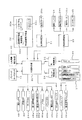
続いて前述したパチンコ機10の電気的構成を図4のブロック図を用いて説明する。
パチンコ機10の電気回路は、図示するように、前述した主制御基板30、賞球制御基板31、特別図柄表示装置32、発射制御基板33、ランプ制御基板34、音制御基板35、前述したプリペイドカードユニット13及びCR精算表示基板42等から構成されている。尚、この回路図には、信号の受け渡しを行うための所謂中継基板及び電源回路等は記載していない。
Next, the electrical configuration of the
As shown in the figure, the electric circuit of the
主制御基板30は、遊技制御プログラムを記憶したROM及び演算等の作業領域として働くRAMを内蔵した8ビットワンチップマイコンを中心とした論理演算回路として構成され、この他各基板又は各種スイッチ類及び各種アクチェータ類との入出力を行うための外部入出力回路も設けられている。
主制御基板30の入力側には、第1種始動口スイッチ36a、普通図柄作動スイッチ38及びび39a、役物連続作動スイッチ(以下、単に「Vスイッチ」と呼ぶ。)40a、カウントスイッチ40b、賞球払出しスイッチ29a、満タンスイッチ43、補給スイッチ44、タッチスイッチ24a等が接続されている。また、出力側には、大入賞口ソレノイド40c、Vソレノイド40d及び普通役物ソレノイド36b等が接続されている。
The
On the input side of the
第1種始動口スイッチ36aは前述した遊技盤22上の普通電動役物36内、普通図柄作動スイッチ38及び39aは各々普通図柄作動ゲート38及び39内、Vスイッチ40aは大入賞口40内の特定領域内、同じくカウントスイッチ40bは大入賞口40内、賞球払出しスイッチ29aは払出し装置29内の球切りモータ29bの下方、満タンスイッチ43は下皿23内、補給スイッチ44は球タンク27内、に各々取り付けられている。ここで、Vスイッチ40aは大入賞口40内に入賞した遊技球が特別装置作動領域(以下、「特別領域」という。)を通過したことを、カウントスイッチ40bは大入賞口40内に入賞する全ての遊技球を、賞球払出しスイッチ29aは球切りモータ29bにより上皿15に排出される遊技球を、満タンスイッチ43は下皿23内に遊技球が満タン状態になったことを、補給スイッチ44は球タンク27内に遊技球が存在することを、タッチスイッチ24aは発射ハンドル24に内蔵され遊技者が発射ハンドル24に触れていることを、各々検出するためのものである。
また、出力側に接続された大入賞口ソレノイド40cは大入賞口40、Vソレノイド40dは大入賞口40内の特別領域、普通役物ソレノイド36bは普通電動役物36の開閉に各々使用されるものである。
The first type start port switch 36a is in the ordinary
Further, the large winning opening solenoid 40c connected to the output side is used for the large winning
特別図柄表示装置32は、前述したLCD32aと、このLCD32aを駆動制御する図柄表示装置制御基板(以下、単に「図柄制御基板」という。)32b及びバックライト及びインバータ基板等の付属ユニット32cから構成されている。図柄制御基板32bは、前述した主制御基板30と同様8ビットワンチップマイコンを中心とした論理演算回路として構成されている。
The special
賞球制御基板31は、主制御基板30からの指令コマンドに従って球切りモータ29bを駆動制御して入賞があった場合に遊技者に賞球としての遊技球を払い出すものであり、マイクロコンピュータを用いた論理演算回路として構成しても良いし、ディスクリートな回路として構成しても良い。この賞球制御基板31は主制御基板30からの指令に従って遊技球を払い出すだけであり、入賞に対応した遊技球が払い出されているか否かの検知は主制御基板30で行われる。
The prize
発射制御基板33は、遊技者が操作する発射ハンドル24の回動量に応じて発射モータ33aを駆動制御するものであり、その他遊技者が発射停止スイッチ24bを押下したとき発射を停止させたり、発射ハンドル24に内蔵されたタッチスイッチ24aがオン状態のときタッチランプ45を点灯させるためのものである。
The
ランプ制御基板34は主としてトランジスタ等の駆動素子から構成されており、主制御基板30からの指令を受けて普通図柄表示装置37、大当りランプやエラーランプ等のランプ類及びLED等の各種ランプ類を点灯表示させるためのものである。
The
音制御基板35は音源IC及びアンプ等から構成されており、主制御基板30の指令を受けてスピーカ46を駆動制御するためのものである。
The
前述した特別図柄表示装置32、賞球制御基板31、発射制御基板33、ランプ制御基板34及び音制御基板35への送信は、主制御基板30からのみ送信することができるよう一方向通信の回路として構成されている。この一方向通信の回路を具体的に示したのが図5及び図6に示す回路図である。
A circuit for one-way communication so that the transmission to the special
図5に示す回路図は主制御基板30と特別図柄表示装置32の図柄制御基板32bとのインターフェイス回路を示したものであり、図6に示す回路図は図柄制御基板32bの受信回路をより詳細に各々示したものである。図に示すように、主制御基板30のCPUと図柄制御基板32bのCPUとは、I/Oポートを介して接続されており、図柄制御基板32bのCPUは主制御基板30からの信号を受信するだけで主制御基板30に対して送信を行うことができないよう構成されている。本具体例では、主制御基板30から図柄制御基板32bへの通信データ(以下、単に「命令コード」ということもある。)は、1コマンドを2バイトで構成し8本のパラレル信号(MD0〜MD7)と割り込み要求信号(MINT)とにより行っている。図7は割り込み要求信号(MINT)とパラレル信号との関係を示す。主制御基板30から割り込み要求(MINT)が送信されると、図柄制御基板32bのCPUに対して割り込み(INT)が発生し、この割り込み処理により図柄制御基板32bのCPUは命令コードをコマンド受信バッファに格納するよう構成している。
The circuit diagram shown in FIG. 5 shows an interface circuit between the
主制御基板30には、その他、前述したプリペイドカードユニット13、CR精算表示基板42が接続されている。CR精算表示基板42は、前述した上皿15の貸出釦16、精算釦17及び残高表示部18等から構成されている。
以上説明した回路構成を有するパチンコ機10が提供するゲーム内容は、従来のものと同様なので簡単な説明に留める。
In addition, the
The game content provided by the
遊技者により操作される発射ハンドル24の回動量に応じて発射モータ33aにより遊技球が遊技盤22上に発射され、発射された遊技球が第1種始動口としての普通電動役物36に入賞すれば第1種始動口スイッチ36aにより検出され、特別図柄表示装置32のLCD32aの画面上に特別図柄を所定時間変動表示した後に静止表示するよう働く。この静止表示した特別図柄が予め定められた特定図柄、例えば「777」等の3桁同一図柄を表示すると「大当り」状態として遊技者に有利なゲーム内容を提供する。大当り状態となるか否かは、遊技球が第1種始動口スイッチ36aにより検出されたとき選択される当否決定乱数の値が所定値であるか否かにより決定される。この当否決定乱数は、例えば2ms毎の微小時間毎にインクリメントされ、例えば0〜249の250種類の整数を繰り返し作成するカウンタであり、発射された遊技球が普通電動役物36内に入賞するタイミングが予測できないランダムなタイミングであることにより乱数として機能する。大当り状態となると、大入賞口40が約30秒間又は遊技球が10個入賞したことがカウントスイッチ40bにより検出されるまでいずれか早く経過する時まで開放され、このとき大入賞口40内に入賞した遊技球が特別領域を通過したことがVスイッチ40aにより検出されると一旦大入賞口40が閉鎖された後に再び開放され、この開放動作を最大16回繰り返す。通常、遊技球1個の入賞に対して15個の遊技球が賞球として払い出すよう構成しているので、1回の大当り状態が発生すると、約2400(=15×10×16)個の遊技球を賞球として獲得することができる。この賞球排出動作は、賞球制御基板31が実行する。尚、大入賞口40の特別領域を開閉するVソレノイド40dは、特別領域に遊技球が1個通過すると特別領域を閉鎖するためのものである。
A game ball is launched onto the
また、発射された遊技球が普通図柄作動ゲート38又は39を通過すると普通図柄作動スイッチ38a又は39aにより検出され、普通図柄表示装置37が所定時間変動表示した後に静止表示し、例えば「7」等の特定の図柄を表示すると例えば約6秒等の所定時間又は遊技球が6個等の所定個数入賞するまでいずれか早く経過する時まで普通電動役物36が開放される。これにより遊技球が普通電動役物36に入賞する機会が大きくなり、遊技者が所定個数の遊技球を獲得することができると共に特別図柄表示装置32の特別図柄を変動表示させる回数が多くなり、大当り状態を発生させる確率が増大する。普通電動役物36を開放させるまでの構成は、前述した「大当り」状態を発生させる構成と略同様なのでその説明は割愛する。
遊技中において前述したランプ制御基板34及び音制御基板35が実行する制御も従来と同様な構成であり、その説明は割愛することにする。
Further, when the launched game ball passes through the normal
The control executed by the
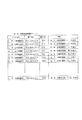
次に主制御基板30と特別図柄表示装置32とで実行される通信の構成を、次頁に示す表1を用いて詳細に説明する。表1は命令コード(以下、「コマンド」ともいう。)の種類とそのコマンドに対応した2バイト命令の内容及び動作内容を示すものである。
Next, the configuration of communication executed between the

表1に示すように、本具体例の主制御基板30と特別図柄表示装置32とのコマンドは、1.電源投入時、2.客待ちデモ、3.図柄変動中、4.大当り開始時、5.大当り中、6.大当り終了時、7.動作異常時、の7種類に大別できる。
As shown in Table 1, the commands of the
1.電源投入時
電源投入時のコマンドは、パチンコ機10に電源が投入されたとき主制御基板30から図柄制御基板32bに送信されるコマンドであり、10Hの動作番号及び01Hの識別番号の2バイト命令で構成されている。図柄制御基板32bがこのコマンドを受信するとROMに書込まれた制御プログラムに従ってLCD32aの画面上に電源投入時のデモ画面を表示する。
例えば、図8に示すように、画面上の特別図柄表示領域50a、50b、50cに各々「7」、「7」、「7」と3桁同一の大当り図柄を表示し、4つの特別図柄保留記憶51a〜51dを所定時間(約5秒)点灯させた後に消灯し、背景画面52上に道場を表示しキャラクタとしてヒーロ(hero)及び悪人(bad)を表示し、ヒーロが悪人と所定時間(約1分)格闘したのち悪人を倒し「ファイヤ」という文字を表示するデモ画面を表示すると共に音制御基板35により「ファイヤ」という効果音を出力する処理を実行する。
1. When the power is turned on, the power-on command is a command transmitted from the
For example, as shown in FIG. 8, the special symbol display areas 50a, 50b, and 50c on the screen display the jackpot symbols that are three digits identical to “7”, “7”, and “7”, respectively, and hold four special symbols on hold. The memories 51a to 51d are turned on after being turned on for a predetermined time (about 5 seconds), the dojo is displayed on the
2.客待ちデモ
客待ちデモのコマンドは、前記電源投入のデモ画面が終了した後、又は遊技者が所定時間(通常約3分間)発射ハンドル24に触れていないと判断されたときに送信されるコマンドであり、20Hの動作番号及び01Hの識別番号の2バイト命令で構成されている。図柄制御基板32bがこのコマンドを受信するとROMに書込まれた制御プログラムに従ってLCD32aの画面上に客待ちのデモ画面を表示する。例えば、特別図柄表示領域50a〜50c上に変動表示される特別図柄の変動パターンを全て順番に表示する。この変動パターンについては次の「3.図柄変動中」で詳細に説明する。このとき、背景画面52上には各々の変動パターンに対応した背景画像及びキャラクタが表示される。この客待ちデモ画面は遊技客が発射ハンドル24を操作するまで全ての変動パターンを順番に表示して一巡した後繰り返し表示する。尚、遊技者が発射ハンドル24に触れているか否かはタッチスイッチ24aの入力により検知することができる。本実施例では、タッチスイッチ24aの入力を主制御基板30に入力する構成としたので、主制御基板30と発射制御基板33との通信を主制御基板30からの一方向通信としながらも前記検知が可能なのである。もちろん、主制御基板30からタッチスイッチ24aのオンオフ情報は発射制御基板33に送信される。このタッチスイッチ24aの入力を発射制御基板33に入力する構成とし、いずれかの又は全ての入賞口に所定時間入賞がないこと、又は遊技盤22面のアウト口41にスイッチを設けてこのスイッチが所定時間オンしないことにより遊技者が遊技を実行していないことを判断する構成としても良い。
2. Customer Waiting Demo The customer waiting demo command is a command that is transmitted after the power-on demonstration screen is completed or when it is determined that the player has not touched the firing handle 24 for a predetermined time (usually about 3 minutes). It consists of a 2-byte instruction with an operation number of 20H and an identification number of 01H. When the
3.図柄変動中
図柄変動中コマンドは、特別図柄変動時に送信されるコマンドであり、表に示すように(1)スタートコード、(2)左停止図柄指定コード、(3)中停止図柄指定コード、(4)右停止図柄指定コード、(5)左図柄確定コード、(6)中図柄確定コード、(7)右図柄確定コード、の7種類のコマンドに分類される。
3. The symbol changing command is a command transmitted at the time of the special symbol changing, and as shown in the table, (1) start code, (2) left stop symbol designation code, (3) middle stop symbol designation code, ( 4) Right stop symbol designation code, (5) Left symbol determination code, (6) Middle symbol determination code, and (7) Right symbol determination code.
(1)スタートコード
スタートコードは、遊技盤22上に発射された遊技球が始動口としての普通電動役物36に入賞したとき送信されるコマンドであり、動作番号として30Hの1バイト命令と識別番号として01Hから1EHの30種類の1バイト命令とから30種類の2バイト命令として構成されている。この30種類の2バイト命令は特別図柄の変動パターンを示すものである。本具体例の30種類の変動パターンは、特別図柄の変動時間、変動態様及び大当りとなる確率の高低とから10種類の通常変動、8種類の短縮変動、4種類の通常リーチ、4種類のセミロングリーチ、2種類のロングリーチ、2種類の全回転からなる。
(1) Start code The start code is a command transmitted when a game ball launched on the
10種類の通常変動は、特別図柄が変動開始してから左、中及び右の全特別図柄が静止(停止)するまでの時間(以下、単に「変動時間」ということもある。)が5秒〜10秒の間の10種類の時間が設定された変動パターンである。
8種類の短縮変動は、特別図柄の保留記憶が1個ある場合、2個ある場合、3個ある場合、4個ある場合、の4種類のパターンと2種類の確率の高低の差とから8種類の変動時間が設定された変動パターンである。
4種類の通常リーチは、変動時間が8秒〜15秒の間の4種類の時間が設定された変動パターンである。ここで、リーチとは、必ずしも大当りとなるとは限らないが大当りの前提として特別図柄の変動が開始してから左特別図柄と中特別図柄とが一致し右特別図柄が変動中であってその図柄が確定していない状態をいう。
4種類のセミロングリーチとは、変動時間が15秒〜25秒の間の4種類の時間が設定された変動パターンである。
2種類のロングリーチとは、変動時間が30秒又は35秒に設定された変動パターンである。尚、リーチの時間が長ければ長いほど右図柄が左及び中図柄と一致する、即ち大当りとなる確率が高くなるよう構成されている。
2種類の全回転とは、全図柄が一斉に変動を開始し一斉に停止する変動パターンをいい、本具体例では変動時間は低確率時で25秒、高確率時で20秒に設定されている。
The 10 types of normal fluctuations take 5 seconds from when the special symbols start to fluctuate until all the left, middle and right special symbols stop (stop) (hereinafter may be simply referred to as “fluctuation time”). It is a fluctuation pattern in which 10 types of time between 10 seconds are set.
The eight types of shortening fluctuations are 8 based on the difference between the four types of patterns and the two types of probabilities in the case where there is one special symbol reserved memory, two cases, three cases, and four cases. This is a variation pattern in which a variation time of a type is set.
The four types of normal reach are variation patterns in which four types of time between the variation times of 8 seconds to 15 seconds are set. Here, the reach is not necessarily a big hit, but as a premise of the big hit, the left special symbol matches the middle special symbol after the start of the change of the special symbol, the right special symbol is changing, and the symbol The state where is not fixed.
The four types of semi-long reach are variation patterns in which four types of time between 15 to 25 seconds are set.
The two types of long reach are fluctuation patterns in which the fluctuation time is set to 30 seconds or 35 seconds. The longer the reach time, the higher the probability that the right symbol matches the left and middle symbols, that is, the big hit.
The two types of full rotations refer to a fluctuation pattern in which all symbols start to change all at once and stop all at once. In this example, the change time is set to 25 seconds for low probability and 20 seconds for high probability. Yes.
これらの30種類の変動パターンは、遊技球が普通電動役物36に入賞したときのカウンタの値により選択される。このパターンを選択するカウンタは、0〜29までの整数を当否決定乱数と同様な手法で作成しているのは言うまでもないことである。
These 30 types of variation patterns are selected according to the value of the counter when the game ball wins the ordinary
(2)左停止図柄指定コード
左停止図柄指定コードは、31Hの動作番号と01H〜0FHの15種類の識別番号とからなる命令コードであり、識別番号が01Hのときは左停止図柄として「0」、02Hのときは「1」、03Hのときは「2」、04Hのときは「3」、05Hのときは「4」、06Hのときは「5」、07Hのときは「6」、08Hのときは「7」、09Hのときは「8」、0AHのときは「9」、0BHのときは「A」、0CHのときは「B」、0DHのときは「C」、0EHのときは「D」、0FHのときは「E」の文字を特別図柄として特別図柄表示領域50aに表示させるためのものである。
(2) Left stop symbol designation code The left stop symbol designation code is an instruction code consisting of an operation number of 31H and 15 types of identification numbers of 01H to 0FH. When the identification number is 01H, “0” is designated as the left stop symbol. "1" for 02H, "2" for 03H, "3" for 04H, "4" for 05H, "5" for 06H, "6" for 07H, “7” for 08H, “8” for 09H, “9” for 0AH, “A” for 0BH, “B” for 0CH, “C” for 0DH, 0EH When “D”, the character “E” is displayed as a special symbol in the special symbol display area 50a.
(3)中停止図柄指定コード
中停止図柄指定コードは、32Hの動作番号と01H〜0FHの15種類の識別番号とからなる命令コードであり、識別番号は前記左停止図柄指定コードの識別番号と同じ意味をもち、各々で指定される文字を特別図柄として特別図柄表示領域50bに表示させるためのものである。
(3) Middle stop symbol designation code The middle stop symbol designation code is an instruction code consisting of an operation number of 32H and 15 types of identification numbers of 01H to 0FH. The identification number is an identification number of the left stop symbol designation code. The characters having the same meaning are displayed in the special symbol display area 50b as special symbols.
(4)右停止図柄指定コード
右停止図柄指定コードは、33Hの動作番号と01H〜0FHの15種類の識別番号とからなる命令コードであり、識別番号は前記左停止図柄指定コードの識別番号と同じ意味をもち、各々で指定される文字を特別図柄として特別図柄表示領域50cに表示させるためのものである。
尚、左、中及び右停止図柄指定コードの識別番号は、遊技球が普通電動役物36に入賞したときのタイミングで0〜14の整数値を繰り返し作成する各々の図柄カウンタより選択される。
(4) Right stop symbol designation code The right stop symbol designation code is an instruction code consisting of an operation number of 33H and 15 types of identification numbers from 01H to 0FH. The identification number is an identification number of the left stop symbol designation code. The characters having the same meaning are displayed in the special symbol display area 50c as special symbols.
The identification number of the left, middle and right stop symbol designation codes is selected from each symbol counter that repeatedly creates an integer value of 0 to 14 at the timing when the game ball wins the ordinary
(5)左図柄確定コード
左図柄確定コードは、変動中の左特別図柄を停止(静止)するために送信する命令コードであり、34Hの動作番号及び01Hの識別番号により構成されている。
(5) Left symbol determination code The left symbol determination code is an instruction code that is transmitted to stop (still) the left special symbol that is fluctuating, and includes an operation number of 34H and an identification number of 01H.
(6)中図柄確定コード
中図柄確定コードは、変動中の中特別図柄を停止するために送信する命令コードであり、35Hの動作番号及び01Hの識別番号により構成されている。
(6) Medium symbol determination code The medium symbol determination code is an instruction code transmitted to stop the changing middle special symbol, and is composed of an operation number of 35H and an identification number of 01H.
(7)右図柄確定コード
右図柄確定コードは、変動中の右特別図柄を停止するために送信する命令コードであり、36Hの動作番号及び01Hの識別番号により構成されている。
(7) Right symbol determination code The right symbol determination code is an instruction code transmitted to stop the changing right special symbol, and includes an operation number of 36H and an identification number of 01H.
4.大当り開始
大当りデモ開始コマンドは、特別図柄表示領域50a〜50cに表示される左、中及び右特別図柄が同一図柄を表示した後から大当り動作が開始されるまでの間に大当りが発生したということを遊技者にアピールする画像を表示するときに使用されるコマンドであり、40Hの動作番号と01Hの識別番号により構成されている。この命令コードを図柄制御基板32bが受信するとLCD32aの画面上に「大当り」等の文字を表示しキャラクタが喜ぶ画像を表示すると共に、音制御基板35により効果音を出力する処理がなされる。
4). Big hit start The big hit demo start command means that a big hit occurs after the left, middle and right special symbols displayed in the special symbol display areas 50a to 50c display the same symbol until the big hit operation starts. This command is used to display an image that appeals to the player, and is composed of an operation number of 40H and an identification number of 01H. When the
5.大当り中
大当り中コマンドは、開放前コード、開放中コード、10カウント入賞コード、V通過コードの4個のコマンドに分類される。
(1)開放前コードは、50Hの動作番号及び01Hの識別番号より構成され、図柄制御基板32bがこの命令コードを入力すると、大入賞口40を開放することを遊技者に知らせる画像を背景画面52に表示する処理を実行する。
(2)開放中コードは、50Hの動作番号及び02Hの識別番号より構成され、図柄制御基板32bがこの命令コードを入力すると、大入賞口40が開放中であることを遊技者に知らせる画像を表示する処理を実行する。
(3)10カウント入賞コードは、50Hの動作番号及び03Hの識別番号より構成され、主制御基板30は大入賞口40に遊技球が入球したことをカウントスイッチ40b又はVスイッチ40aにより検知する毎にこの命令コードを送信する。図柄制御基板32bがこの命令コードを入力すると、入力する毎にその値をインクリメントしその値を背景画面52上に表示する処理を行う。これにより、画面上には、大入賞口40に遊技球が入賞する毎に零から10個までの個数表示がなされる。
(4)V通過コードは、50Hの動作番号及び04Hの識別番号より構成され、主制御基板30は大入賞口40内の特別領域を遊技球が通過したことをVスイッチ40aにより検知するとこの命令コードを送信する。図柄制御基板32bがこの命令コードを入力すると画面に「V」の文字を大きく表示し大入賞口40が閉鎖した後再び開放することを遊技者に知らせる。
5. Big hit Medium hit big hit commands are classified into four commands: pre-open code, open code, 10-count winning code, and V pass code.
(1) The pre-release code is composed of an operation number of 50H and an identification number of 01H. When the
(2) The open code is composed of an operation number of 50H and an identification number of 02H, and when the
(3) The 10-count winning code is composed of an operation number of 50H and an identification number of 03H, and the
(4) The V passing code is composed of an operation number of 50H and an identification number of 04H. When the
6.大当り終了
大当り終了コマンドは、大当り動作が終了したとき、即ち大入賞口40が16回の開放動作を終了したとき、または16回まで継続しなくとも開放中に遊技球が特別領域を通過しなかったときに送信される命令コードであり、60Hの動作番号及び01Hの識別番号より構成される。図柄制御基板32bがこの命令コードを入力すると大当りが終了したことを遊技者に知らせるメッセージを表示すると共に、高確率状態が継続する場合には「ラッキー!」の文字を、高確率が継続しない場合には「残念!」の文字を表示する処理を実行する。ここで、高確率が継続するとは、特別図柄が「777」又は「333」等の特定図柄で大当りが発生したとき、大当り動作終了後に大当りが発生する確率を、例えば1/250から1/50にすることを言う。さらに詳しく説明すれば当否決定乱数に使用されるカウンタの取り得る範囲を0〜249の範囲から0〜49に変更することを言う。
6). End of jackpot The jackpot end command indicates that the game ball does not pass through the special area when the jackpot operation is ended, that is, when the big winning
7.動作異常時
動作異常時コマンドは、パチンコ機10に異常が発生したときに送信される命令コマンドであり、本具体例では、70H01HのE1エラーコード、70H02HのE2エラーコード、70H03HのE3エラーコードより構成されている。本具体例ではE1エラーコードは、テンカウント異常エラーであり大入賞口40が開放したときに遊技球が1個も検知されない場合に出力され、E2エラーコードは下皿23が満杯で満タンスイッチ43がオンしたとき出力され、E3エラーコードは補給スイッチ44がオンしたとき出力される。尚、これらの異常時コマンドを送信することにより表示されるエラーメッセージは、異常が解除されたとき送信されるエラー解除信号により消去される。
7). When abnormal operation The abnormal operation command is an instruction command that is sent when an abnormality occurs in the
ここで、次に示す表2及び図9を用いて変動パターンの1例を具体的に説明することにする。表2及び図9に示すタイミングチャートは通信タイミングの1例を示すものである。
遊技球が始動口としての普通電動役物36に入賞すると、この入賞のタイミングで表1に示したスタートコードの30種類のうちの1つの変動パターンが選択され、この選択された命令コードが主制御基板30から図柄制御基板32bに送信される(表2 番号1)。図柄制御基板32bは送信された命令コードを受信すると、特別図柄表示領域50a〜50c上で左特別図柄、中特別図柄及び右特別図柄を一斉に変動開始する(図9タイミングチャート ポイント(1))。
Here, an example of the variation pattern will be specifically described with reference to Table 2 and FIG. The timing chart shown in Table 2 and FIG. 9 shows an example of communication timing.
When the game ball wins the ordinary
主制御基板30は、入賞時に選択された左停止図柄指定コードをスタートコードを送信した直後に送信する(表2 番号2)。この命令コードを図柄制御基板32bが受信すると命令コードに応じた左特別図柄で停止表示すべく変動パターンに応じて変動スピードを調節制御する(図9タイミングチャート ポイント(2))。そして、主制御基板30から左図柄確定コードを受信したタイミングで指定された左特別図柄を停止表示する(表2 番号3)(図9タイミングチャート ポイント(3))。主制御基板30が左図柄確定コードを送信するタイミングは、選択された変動パターンに従って決定される。この構成により変動図柄を停止表示するタイミングは、主制御基板30が完全に掌握することになる。
The
同様な手順により主制御基板30は中停止図柄指定コード、中図柄確定コード、右停止図柄指定コード及び右図柄確定コードを次々と送信し(表2 4,5,6,7)、図柄制御基板32bは受信した命令コードに従って画像を制御する(図9タイミングチャート ポイント(4)(5)(6)(7))。
前述した処理により、本具体例では特別図柄表示領域50aには「4」、特別図柄表示領域50bには「5」、特別図柄表示領域50cには「5」が各々表示される。
By the same procedure, the
Through the above-described processing, “4” is displayed in the special symbol display area 50a, “5” is displayed in the special symbol display area 50b, and “5” is displayed in the special symbol display area 50c.
以上詳細に説明した本実施例によると、主制御基板30から図柄制御基板32bに対して特別図柄の一連の変動態様を予め送信する構成としたことにより図柄制御基板32bはこの変動パターンに従って画像を制御すれば良く、主制御基板30の負担が極めて軽減することができると共に図柄制御基板32bの制御の自由度が一層高まったという極めて優れた効果を有する。
この結果、主制御基板30が他の制御基板、即ち賞球制御基板31、発射制御基板33、ランプ制御基板34、音制御基板35等の各基板との処理を好適に実行することができるという効果を奏する。一方、図柄制御基板32bにおいては主制御基板30に拘束される度合いが激減したことにより、特別図柄表示領域50a〜50c以外の画面上においてストーリ的な画像を表示制御することが一層容易になるという優れた効果も奏する。このとき、表示制御される画像は、主制御基板30からのスタートコードが送信される毎にストーリ展開する構成とすること等が考えられる。
また、本実施例では、図柄の変動パターンを指示するスタートコードを30種類のパターンの中から遊技球が普通電動役物36に入賞するタイミングで選択する構成としたことにより、表示される画像のランダム性を有するという優れた効果を有している。
更に、本実施例では、図柄の変動を開始するスタートコードばかりでなく、各特別図柄の静止時期を主制御基板30から指示する構成としたことにより、遊技機の型式試験認定の試験機関等においても、主制御基板30から図柄制御基板32bへの送信タイミングを測定する場合、スタートコードを送信するタイミング及び各特別図柄確定コードを送信するタイミングを測定すれば画面上の特別図柄の変動開始及び停止時期をリアルタイムに、かつ正確に測定することができるという優れた効果も奏する。
[第2実施例]
According to the present embodiment described in detail above, the
As a result, the
In this embodiment, the start code for designating the pattern variation pattern is selected from the 30 patterns at the timing when the game ball wins the ordinary
Further, in this embodiment, not only the start code for starting the variation of symbols, but also a configuration in which the stationary time of each special symbol is instructed from the
[Second Embodiment]
次に第2の具体例について説明する。
第2の具体例では、第1の具体例で用いた表1に示すコマンドの替わりに次に示す表3の各コマンドを、また表4に示す変動パターン対応テーブルを使用する構成としたものであり、これ以外は第1の具体例と略同様の構成である。
第2の具体例では、表3に示すように第1の具体例で使用した左、中及び右図柄確定コードの使用をなくした構成としたものであり、主制御基板30は遊技球が普通電動役物36に入賞するとスタートコード及び左、中、及び右停止図柄指定コードを送信する。即ち、図柄制御基板32bに対して各図柄の停止を指示しない。これに対し図柄制御基板32bは受信した変動パターンに対応した各特別図柄の変動時間(停止時間)を表4のテーブルから読み取り、読みとった変動時間に従って各特別図柄を変動し停止する。
Next, a second specific example will be described.
In the second specific example, instead of the command shown in Table 1 used in the first specific example, each command shown in Table 3 below is used, and the variation pattern correspondence table shown in Table 4 is used. Except this, the configuration is substantially the same as the first specific example.
In the second specific example, as shown in Table 3, the left, middle and right symbol determination codes used in the first specific example are not used, and the
第2の具体例では、主制御基板30は遊技球が始動口としての普通電動役物36に入賞したタイミングで選択されたスタートコード及び各停止図柄指定コードを図柄制御基板32bに送信するだけなので主制御基板30の負担を一層軽減することができるという優れた効果を有する。同様に、図柄制御基板32bにおいても、主制御基板30から図柄停止の指示を受けることがないので、画像制御の自由度を一層高めることができ画面上で自由に画像を演出することができるという極めて優れた効果を奏する。
画面上での自由な画像を演出する構成としては、背景画面52上でスタートコードが送信される毎に物語りを展開する構成とし、遊技者が続く物語の展開および結末を知りたいと思わせ、遊技を途中で終わらせたくないと思わせる心理的効果を得ることができるような構成とすることが考えられる。このとき、大当りが発生すれば、強制的に物語の結末を表示する構成としても良いし、大当りか否かに関係なく物語を展開していく構成としても良い。これらの物語の展開を構成するに際して、画像制御装置は特別図柄の変動パターンの時間が予めわかっているので、この時間内には主制御基板30から指示がないものと判断し、この期間自由な演出ができるのである。
また、画面上での自由な画像を演出する構成として、特別図柄が変動開始して静止するまでは背景画面52上の物語の展開を無くし、特別図柄が変動しない状態で遊技者が発射ハンドル24を操作している場合に物語を展開する構成としても良い。
In the second specific example, the
As a configuration for producing a free image on the screen, the story is developed every time a start code is transmitted on the
Further, as a configuration for producing a free image on the screen, the story is not developed on the
次に第3の具体例を次に示す表5及び図10に示すタイミングチャートに従って説明する。
前述した第1実施例の「6.大当り終了」の命令コード送信時において、特別図柄が「777」又は「333」等の特定図柄の場合に高確率に移行することを説明したが、第3実施例は、特別図柄の特定図柄ではなく確率変動判定図柄を用いるものである。ここで、表5に示す命令コードは、第1の具体例に示した表1における「6.大当り終了」の命令コードのみを変更したものであり、その他の命令コードは同一内容である。
Next, a third specific example will be described with reference to the following Table 5 and the timing chart shown in FIG.
It has been explained that when the command code of “6. End of jackpot” in the first embodiment described above is transmitted with a high probability when the special symbol is a specific symbol such as “777” or “333”. In the embodiment, a probability variation determination symbol is used instead of a special symbol of a special symbol. Here, the instruction code shown in Table 5 is obtained by changing only the instruction code “6. End of jackpot” in Table 1 shown in the first specific example, and the other instruction codes have the same contents.
第3の具体例では、大当り動作が終了時に主制御基板30から図柄制御基板32bに対してまず判定スタートコードが送信され、この直後に停止図柄指定コード、変動終了時に判定図柄確定コードが送信される。本具体例では、スタートコードの識別番号は、01Hから05Hの5種類の変動パターンで構成されている。この識別番号に対応して変動する図柄(画像)の態様は、勝負事の画像を変動させるものである。勝負事は、スポーツ、格闘技、将棋や囲碁のゲーム等の勝ち負けが決定するものであれば何でも良く、これらの勝負事がストーリ(物語)展開する変動パターンが遊技球が普通電動役物36に入賞するときに選択されるのである。
停止図柄指定コードは、本具体例では、高確率に移行する場合の「ラッキー!」という文字を表示させるためのものと、高確率に移行しない場合の「残念!」という文字を表示させるための2種類のコードよりなる。高確率に移行するか否かは、遊技球が普通電動役物36に入賞したときに選択されるカウンタ(当否決定乱数)の値により決定され、大当りのうち1/2の確率で高確率に移行する場合はカウンタは0〜1の範囲の整数値を、1/3の確率で高確率に移行する場合はカウンタは0〜2の範囲の整数値を前述した当否決定乱数と同様の手法により作成している。主制御基板30は、このカウンタの値を遊技球が普通電動役物36に入賞したときに記憶し、大当り動作終了時に記憶したカウンタの値を読み出し、読み出した値が特定の値であれば高確率に移行すると判定する。尚、遊技球が入賞したときに高確率に移行するか否か判定しこの判定した結果を記憶しても良い。
In the third specific example, a determination start code is first transmitted from the
In this specific example, the stop symbol designation code is used to display the characters “Lucky!” When shifting to a high probability and to display the characters “Sorry!” When not shifting to a high probability. It consists of two types of codes. Whether or not to shift to a high probability is determined by the value of a counter (randomness determination random number) selected when a game ball wins the ordinary
高確率に移行する場合は勝負に勝った物語を展開した後に「ラッキー!」の文字を表示し、高確率に移行しない場合は勝負に負ける物語を展開した後に「残念!」の文字を表示するのである。この変動のタイミングの1例を示したのが図10に示すタイミングチャートである。確率変動判定図柄は、図に示すように、大入賞口40が16回目の開放動作を終了した後から変動開始され、変動動作が終了した後に表示時間が設定され特別図柄が変動開始する。図中において、条件装置は確率変動判定図柄の変動が終了するまでを作動状態として扱っているが、16回目の作動が終了した時点で作動終了(図中に点線で示す。)と扱っても良い。このとき、条件装置の作動が終了した時点で判定スタートコードを主制御基板30が送信する構成としても良い。
尚、大入賞口40が16回開放前であっても、開放中に遊技球が特別領域を通過しなければその開放の回で大当り動作が終了するのは言うまでもないことである。また、本具体例では、勝負事の画像を変動表示した後、高確率に移行するか否かを示す図柄を表示するよう構成したが、特別図柄と同様に確率変動判定図柄を変動表示して静止時の図柄で高確率に移行するか否かを示す構成としても何等差し支えない。
When moving to a high probability, the word “Lucky!” Is displayed after the story that won the game is expanded. When not moving to the high probability, the word “Sorry!” Is displayed after expanding the story that loses the game. It is. An example of the timing of this variation is shown in the timing chart shown in FIG. As shown in the figure, the probability variation determination symbol starts to fluctuate after the special winning
Needless to say, even if the big winning
第3の具体例によると、高確率に移行するか否かは大当り動作が終了してから示されることになる。これにより、従来のように大当り発生時に移行するか否かが既に示されているものとは異なり、大当り動作が終了するまで遊技者に楽しみを維持させることができるという優れた効果を有する。また、高確率に移行するか否かを表示する一連の変動パターンは、大当り動作終了時に予め送信されるので、図柄制御基板32bは判定図柄確定コードが送信されるまで物語を自由に展開させることができる。この効果は、判定スタートコードに図柄の静止タイミングを指示する構成とすれば一層顕著なものとなる。
According to the third specific example, whether or not to shift to a high probability is indicated after the jackpot operation ends. Thus, unlike the conventional case where it is already shown whether or not to shift when a big hit occurs, it has an excellent effect that the player can keep enjoying until the big hit operation is finished. In addition, since a series of variation patterns indicating whether or not to shift to a high probability is transmitted in advance at the end of the jackpot operation, the
[第4実施例]
次に図11〜図18を用いて第4の具体例について説明する。
第4の具体例では、第1の具体例で用いた表3に示した図柄変動中のコマンドコードとして図11〜図13に示すコマンドコードを使用する構成であり、その他の構成については第1の具体例を援用することにする。
第4の具体例では、図11に示すように、スタートコードとしての変動パターンは特別図柄の変動時間を指示するものであり、本実施例では72パターン容易されている。この72通りの変動パターンは、遊技球が始動口としての普通電動役物36に入賞したタイミングで抽出される前述した当否決定乱数による当否の結果、同じく遊技球が始動口としての普通電動役物36に入賞したタイミングで抽出される前述した左、中及び右停止図柄指定コードの識別番号の元となる各図柄カウンタの値、及び当否決定乱数が高確率状態であるか否か等の各要素に基づき決定される。この図11の選択テーブルにより選択される変動パターンは、各特別図柄が順番に停止するのか、一斉に停止するのかといった変動態様の情報も含み、順番に停止する場合には、左特別図柄の変動時間、中特別図柄の変動時間等の情報も含まれる。
図12に示す特別図柄選択テーブルは、特別図柄の変動停止後に特別図柄作動領域50a〜50c上に停止表示される左特別図柄、中特別図柄及び右特別図柄を指示するものである。このコマンドも抽出された前記各図柄カウンタの値に基づき決定される。また、図13に示す図柄停止コマンドは、左、中及び右特別図柄を停止させるときに用いるコマンドである。
次にこれらのコマンドを用いて主制御基板30のマイコンが図柄制御基板32bにコマンドを送信する制御を、図14〜図15に示すタイミングチャートに従って説明することにする。
[Fourth embodiment]
Next, a fourth specific example will be described with reference to FIGS.
In the fourth specific example, the command code shown in FIGS. 11 to 13 is used as the command code during the symbol variation shown in Table 3 used in the first specific example. The specific example of will be used.
In the fourth specific example, as shown in FIG. 11, the variation pattern as the start code indicates the variation time of the special symbol. In this embodiment, 72 patterns are facilitated. These 72 variation patterns are obtained as a result of the success / failure determination random number extracted at the timing when the game ball wins the ordinary
The special symbol selection table shown in FIG. 12 indicates a left special symbol, a middle special symbol, and a right special symbol that are stopped and displayed on the special symbol operation areas 50a to 50c after the variation of the special symbol is stopped. This command is also determined based on the extracted value of each symbol counter. Also, the symbol stop command shown in FIG. 13 is a command used to stop the left, middle and right special symbols.
Next, the control in which the microcomputer of the
遊技球が普通電動役物36に入賞したことが検出されると、このときのタイミングで当否決定乱数、各図柄カウンタ等の値が抽出される。この抽出された当否決定乱数の値に基づき大当りか否かが判定され、各図柄カウンタの値に基づき大当り図柄又は外れ図柄が決定される。大当りの場合には、大当り図柄から大当り動作終了後に高確率に移行するか否かも判断される。そして、大当り判定の結果と決定された各図柄の種類と高確率中であるか否かの状態とにより72種類の変動パターンの1つが選択される。変動パターンが選択されると、各特別図柄が順次停止する場合、主制御基板30のマイコンは図柄制御基板32bにスタートコードとして選択された変動パターンを出力する(図14 ポイントP1)。変動パターンが出力された後、4ms毎に図12の選択テーブルから決定された左特別図柄を指示するコマンド、中特別図柄を指示するコマンド、及び右特別図柄を指示するコマンドが送信される(図14 ポイントP2、P3、P4)。そして、各特別図柄の変動停止時間になると、図13に示した図柄停止コマンドが送信される(図14 ポイントP5,P6,P7)。
また、各特別図柄が一斉に停止する場合、図15のポイントP8〜P13で示す通りのタイミングとなる。
When it is detected that the game ball has won the ordinary
Moreover, when each special symbol stops simultaneously, it becomes a timing as shown by the points P8-P13 of FIG.
一方、変動パターンを受信した図柄制御基板32bのマイコンは、図14及び図15に示すように、変動パターンを受信したときから各特別図柄を特別図柄作動領域50a〜50c上で一斉に低速で変動開始し、途中で中速から高速に変速し、停止時間に近くなると減速して低速に変速し指示された各特別図柄で揺れ動作を実行し、図柄停止コマンドを受信すると指示された特別図柄で停止させる制御を実行する。
このとき、画面上の背景画面52上に、受信した変動パターンの有する情報に従って、図16及び図17の選択テーブルに基づきキャラクタが出現し、背景画面52が変更される制御を図柄制御基板32bが実行する。
前述したように、主制御基板30から図柄制御基板32bに選択された変動パターン、停止表示される各特別図柄及び図柄停止コマンドが出力されるが、これらの各コマンドが図柄制御基板32bに何等かの原因、例えば電気的ノイズ等により受信されなかったときに図柄制御基板32bが実行するエラー処理を説明する。
On the other hand, as shown in FIGS. 14 and 15, the microcomputer of the
At this time, on the
As described above, the variation pattern selected from the
図18に示すコマンド異常対応テーブルは、各コマンドが入力されなかったときの図柄制御基板32bが実行する処理を示したものである。
ここでは、便宜のためにエラー処理を8パターンに分けて説明することにする。尚、図中の「○」はコマンドが正常に受信された場合を示し、「×」は受信できなかった場合を示す。
1.エラー処理ER1
エラー処理ER1は、変動パターンと図柄停止コマンドが正常に受信され、各指定特別図柄が1つ以上受信できなかった場合である。
このエラー処理ER1では、変動パターン(変動開始コマンド)入力後、1秒後に画面上に「通信エラー」の文字を表示し、受信できなかった指定特別図柄として「×」を表示する処理が実行される。
この正常に受信できなかった特別図柄が大当りを示す特別図柄の場合には、次に主制御基板30から大当り開始コマンドが送信されてくるので、大入賞口40が突然開放し遊技者が驚くといった不具合は無い。
また、外れ図柄の場合には、次の入賞に対応したコマンドが送信されてくるので不具合は無い。次の入賞が暫く無い場合、又は所謂「保留記憶」が無い場合には、主制御基板30は所定時間経過後に客待ちデモコマンドを送信するので「通信エラー」が表示され続けることはない。
The command abnormality correspondence table shown in FIG. 18 shows processing executed by the
Here, for convenience, error processing will be described in eight patterns. In the figure, “◯” indicates a case where the command is normally received, and “X” indicates a case where the command is not received.
1. Error handling ER1
Error processing ER1 is a case where the fluctuation pattern and the symbol stop command are normally received, and one or more designated special symbols cannot be received.
In this error process ER1, a process of displaying a character “communication error” on the screen one second after inputting a fluctuation pattern (fluctuation start command) and displaying “x” as a designated special symbol that could not be received is executed. The
If the special symbol that could not be received normally is a special symbol indicating a big hit, then a big hit start command is transmitted from the
In the case of an off symbol, there is no problem because a command corresponding to the next winning is transmitted. When there is no next winning for a while, or when there is no so-called “holding storage”, the
2.エラー処理ER2
エラー処理ER2は、変動パターンと各指定特別図柄が正常に受信され、図柄停止コマンドが受信できなかった場合である。
このエラー処理ER2では、各特別図柄の変動時間経過後に停止図柄で揺れ変動を実行する。このエラー処理による揺れ変動は、各特別図柄の変動時間経過後に各特別図柄毎に揺れ変動を実行しても良いし、右特別図柄の変動時間経過後、即ち全ての特別図柄の変動時間経過後に一斉に揺れ変動を実行しても良い。
エラー処理ER2においても、揺れ変動後のその後の処理はエラー処理ER1と同様の処理が実行される。
2. Error handling ER2
Error processing ER2 is when the variation pattern and each designated special symbol are normally received and the symbol stop command cannot be received.
In this error process ER2, the fluctuation variation is executed with the stop symbol after the variation time of each special symbol has elapsed. The fluctuation due to this error processing may be executed for each special symbol after the variation time of each special symbol elapses, or after the variation time of the right special symbol, that is, after all the special symbols have elapsed. You may perform shaking fluctuation all at once.
Also in the error process ER2, the subsequent process after fluctuation fluctuation is executed in the same way as the error process ER1.
3.エラー処理ER3
エラー処理ER3は、変動パターンが正常に受信され、各指定特別図柄のいずれかと図柄停止コマンドが受信できなかった場合である。
このエラー処理ER3では、各特別図柄の変動時間経過後に停止図柄で揺れ変動を実行する。受信できなかった指定特別図柄は、前回受信した指定特別図柄で揺れ変動を実行する。揺れ変動の開始時期はエラー処理ER2と同様である。
3. Error handling ER3
Error processing ER3 is when the variation pattern is normally received and any of the designated special symbols and the symbol stop command cannot be received.
In this error process ER3, the fluctuation fluctuation is executed with the stop symbol after the fluctuation time of each special symbol has elapsed. For the designated special symbol that could not be received, the fluctuation fluctuation is executed with the designated special symbol received last time. The start time of the fluctuation fluctuation is the same as that of the error processing ER2.
4.エラー処理ER4
エラー処理ER4は、変動パターンのみが正常に受信されない場合である。
このエラー処理ER4では、特別図柄は変動せず、最初の指定特別図柄を受信時に「通信エラー」を表示する。
4). Error handling ER4
Error processing ER4 is a case where only the variation pattern is not normally received.
In this error processing ER4, the special symbol does not change, and “communication error” is displayed when the first designated special symbol is received.
5.エラー処理ER5
エラー処理ER5は、変動パターンと各指定特別図柄のいずれかが正常に受信されない場合である。
このエラー処理ER5では、特別図柄は変動せず、最初に受信した指定特別図柄の受信時に「通信エラー」を表示する。また、指定特別図柄を受信できなかった特別図柄は「×」を表示する。この「×」を表示するタイミングは、各特別図柄の停止コマンド受信時に表示しても良いし、全ての特別図柄の変動時間経過後に一斉に表示しても良い。
5. Error handling ER5
The error process ER5 is a case where either the variation pattern or each designated special symbol is not normally received.
In this error processing ER5, the special symbol does not change, and “communication error” is displayed when the first received special symbol is received. In addition, “×” is displayed for a special symbol for which the designated special symbol cannot be received. The timing for displaying “x” may be displayed when a stop command for each special symbol is received, or may be displayed at the same time after the fluctuation time of all the special symbols has elapsed.
6.エラー処理ER6
エラー処理ER6は、図柄停止コマンドのみが正常に受信された場合である。
このエラー処理ER6では、特別図柄は変動せず、図柄停止コマンドを受信時に「通信エラー」を表示し、各特別図柄として「×」を表示する。通信エラー及び「×」を表示するタイミングは、エラー処理ER5と同様である。
6). Error handling ER6
Error processing ER6 is when only the symbol stop command is received normally.
In this error processing ER6, the special symbol does not change, “communication error” is displayed when the symbol stop command is received, and “x” is displayed as each special symbol. The timing for displaying the communication error and “x” is the same as in the error processing ER5.
7.エラー処理ER7
エラー処理ER7は、指定特別図柄のいづれかのみが受信された場合である。
このエラー処理ER7では、特別図柄は変動せず、最初の指定特別図柄を受信時に「通信エラー」を表示する。
7). Error handling ER7
Error processing ER7 is when only one of the designated special symbols is received.
In this error processing ER7, the special symbol does not change, and “communication error” is displayed when the first designated special symbol is received.
8.エラー処理ER8
エラー処理ER8は、全てのコマンドが受信できない場合である。
このエラー処理ER8では、特別図柄は変動せず、「通信エラー」も表示しない。この場合でもエラー処理ER1と同様のその後の処理が実行されるので、遊技者に不利益を与えるようなことはない。
8). Error handling ER8
Error processing ER8 is when all commands cannot be received.
In this error processing ER8, the special symbol does not change and “communication error” is not displayed. Even in this case, since the subsequent processing similar to the error processing ER1 is executed, there is no disadvantage to the player.
以上、詳細に説明した第4の具体例では、変動パターンの指示コマンド、3つの特別図柄の指定コマンド、図柄停止コマンドの各コマンドの受信異常の組み合わせに対応して異なったエラー処理を実行し、全てのコマンドが受信できない場合以外には揺れ変動を実行し、またエラー表示を実行している。これにより、遊技者には、通信エラーが発生しているということが認識でき、例えば、大当りの発生が表示されない場合が生じたとしても、遊技者の注意を喚起しているので遊技者の不利益を最小限に抑えることができるという効果を奏する。また、全ての特別図柄が同一である大当り表示と大当り発生の表示とが共に表示されない場合は皆無と考えられ、また、係る場合でも音声により大当り発生の音声出力が為されるので遊技者に不測の不利益を与えることはない。更に、本具体例では、通信の異常により外れ図柄が正確に表示されないときでも、前回の指定図柄を用いて外れ表示を極力表示するよう実行しているので遊技者が遊技の状態を認識することができるという効果を発揮している。 As described above, in the fourth specific example described in detail, different error processing is executed corresponding to a combination of reception abnormality of each command of the change pattern instruction command, the three special symbol designation commands, and the symbol stop command, Except when all commands cannot be received, fluctuation fluctuation is executed and error display is executed. As a result, the player can recognize that a communication error has occurred. For example, even if the occurrence of a jackpot is not displayed, the player is alerted because the player is alerted. There is an effect that the profit can be minimized. In addition, it is considered that none of the jackpot display and the jackpot occurrence display with the same special symbol are displayed at all, and even in such a case, since the sound output of the jackpot occurrence is made by voice, it is unexpected to the player. There will be no disadvantage. Furthermore, in this specific example, even when the out symbol is not correctly displayed due to a communication error, the player recognizes the state of the game because the out symbol display is executed as much as possible using the previous designated symbol. It has the effect of being able to.
10・・・・・パチンコ機
22・・・・・遊技盤
24・・・・・発射ハンドル
24a・・・・・タッチスイッチ
30・・・・・主制御基板
31・・・・・賞球制御基板
32・・・・・特別図柄表示装置
32a・・・・・LCDパネルユニット(LCD)
32b・・・・・図柄表示装置制御基板(図柄制御基板)
33・・・・・発射制御基板
34・・・・・ランプ制御基板
35・・・・・音制御基板
36・・・・・普通電動役物(始動口)
36a・・・・・第1種始動口スイッチ
37・・・・・普通図柄表示装置
40・・・・・大入賞口
40a・・・・・役物連続作動スイッチ(VSW)
40b・・・・・テンカウントスイッチ(カウントSW)
50a、50b、50c
・・・・・特別図柄表示領域
52・・・・・背景画面
hero、bad
・・・・・キャラクタ
10 ... Pachinko machine
22 ... Game board
24 ... Launch handle 24a ...
32b ... Symbol display device control board (design control board)
33 ...
36a:
40b ... Ten count switch (Count SW)
50a, 50b, 50c
・ ・ ・ ・ ・ Special
·····charactor
Claims (2)
該主制御基板により遊技者に有利なゲーム内容とするか否かを決定する毎に画面上の複数の図柄を変動表示した後、遊技者に有利なゲーム内容であるか否かを示す図柄の組み合わせの画像で静止表示するよう制御する図柄制御基板と、
を含む遊技機において、
前記主制御基板は、前記図柄の変動表示における変動の態様を指示する変動パターンをコード化したコマンドコードを送信する構成を有し、一方、図柄制御基板では、受信したコマンドコードに従って画面上に図柄を表示するよう構成し、
前記主制御基板は、
前記コマンドコードとして、前記図柄の最初の図柄が変動開始してから最後の図柄が停止するまでの1回の変動表示について設定された変動時間及び大当りか否かの情報を示す予め複数種類以上パターン化した変動パターンを選択するスタートコードを有し、
前記主制御基板のCPUは、前記タイミングに起因していずれか1つのスタートコードを選択し、前記選択されたスタートコードを前記図柄制御基板に送信し、
前記主制御基板のCPUは、遊技者が遊技を実行していないと判断したときには、客待ちデモコマンドを前記図柄制御基板に送信し、
一方、前記図柄制御基板のCPUは、
前記1つのスタートコードを受信し、受信したスタートコードの大当たりか否かを示す情報に従って選択された前記図柄の組み合わせの画像を、前記受信したスタートコードが示す変動時間の経過後に静止表示させるとともに、該図柄の組み合わせの画像以外の画面上において前記スタートコードを受信する毎に前回の図柄の変動から続く物語の展開をする画像構成とし、
前記客待ちデモコマンドを受信すると客待ちのデモ画面を画面上に表示することを特徴とする遊技機。 A main control board for determining whether or not the game ball launched on the game board surface wins a specific winning opening or a game content advantageous to the player due to the timing of passing the specific passing opening;
Each time the main control board determines whether or not the game content is advantageous to the player, a plurality of symbols on the screen are variably displayed, and then the symbol indicating whether or not the game content is advantageous to the player A pattern control board that controls to display a combination image statically;
In gaming machines including
The main control board has a configuration for transmitting the command code obtained by coding the variation pattern for instructing the aspect of change in the variable display of the symbols, while in symbol control board, screen I follow the command code received Configure to display the design on top,
The main control board is
As the command code, a plurality of patterns in advance indicating a variation time set for one variation display from the start of variation of the first symbol of the symbol to the stop of the last symbol and whether or not a big hit is set. Has a start code to select the variation pattern
The CPU of the main control board selects any one start code due to the timing, and transmits the selected start code to the symbol control board,
When the CPU of the main control board determines that the player is not playing a game, it sends a customer waiting demo command to the symbol control board,
On the other hand, the CPU of the symbol control board is
Receiving the one start code, and displaying the image of the combination of symbols selected according to the information indicating whether or not the received start code is a big hit after a lapse of the fluctuation time indicated by the received start code, Each time the start code is received on a screen other than the image of the symbol combination, an image configuration that develops the story that continues from the previous symbol variation,
A gaming machine, wherein when receiving the customer waiting demonstration command, a customer waiting demonstration screen is displayed on the screen.
Priority Applications (1)
| Application Number | Priority Date | Filing Date | Title |
|---|---|---|---|
| JP2006137274A JP4189501B2 (en) | 1999-02-25 | 2006-05-17 | Game machine |
Applications Claiming Priority (2)
| Application Number | Priority Date | Filing Date | Title |
|---|---|---|---|
| JP4784599 | 1999-02-25 | ||
| JP2006137274A JP4189501B2 (en) | 1999-02-25 | 2006-05-17 | Game machine |
Related Parent Applications (1)
| Application Number | Title | Priority Date | Filing Date |
|---|---|---|---|
| JP2003315291A Division JP3944581B2 (en) | 1999-02-25 | 2003-09-08 | Game machine |
Publications (3)
| Publication Number | Publication Date |
|---|---|
| JP2006212459A JP2006212459A (en) | 2006-08-17 |
| JP2006212459A5 JP2006212459A5 (en) | 2007-11-29 |
| JP4189501B2 true JP4189501B2 (en) | 2008-12-03 |
Family
ID=36976108
Family Applications (1)
| Application Number | Title | Priority Date | Filing Date |
|---|---|---|---|
| JP2006137274A Expired - Lifetime JP4189501B2 (en) | 1999-02-25 | 2006-05-17 | Game machine |
Country Status (1)
| Country | Link |
|---|---|
| JP (1) | JP4189501B2 (en) |
Families Citing this family (8)
| Publication number | Priority date | Publication date | Assignee | Title |
|---|---|---|---|---|
| JP5564912B2 (en) * | 2009-10-29 | 2014-08-06 | 株式会社三洋物産 | Game machine |
| JP5859486B2 (en) * | 2013-06-11 | 2016-02-10 | 京楽産業.株式会社 | Game machine |
| JP7042510B2 (en) * | 2019-12-24 | 2022-03-28 | 京楽産業.株式会社 | Pachinko machine |
| JP7042509B2 (en) * | 2019-12-24 | 2022-03-28 | 京楽産業.株式会社 | Pachinko machine |
| JP7042511B2 (en) * | 2019-12-24 | 2022-03-28 | 京楽産業.株式会社 | Pachinko machine |
| JP7042513B2 (en) * | 2019-12-24 | 2022-03-28 | 京楽産業.株式会社 | Pachinko machine |
| JP7042512B2 (en) * | 2019-12-24 | 2022-03-28 | 京楽産業.株式会社 | Pachinko machine |
| JP7090911B2 (en) * | 2019-12-24 | 2022-06-27 | 京楽産業.株式会社 | Pachinko machine |
-
2006
- 2006-05-17 JP JP2006137274A patent/JP4189501B2/en not_active Expired - Lifetime
Also Published As
| Publication number | Publication date |
|---|---|
| JP2006212459A (en) | 2006-08-17 |
Similar Documents
| Publication | Publication Date | Title |
|---|---|---|
| JP3608606B2 (en) | Game machine | |
| JP2019054995A (en) | Game machine | |
| JP4189501B2 (en) | Game machine | |
| JP6555601B2 (en) | Game machine | |
| JP4448907B2 (en) | Bullet ball machine | |
| JP2007038028A (en) | Pinball game machine | |
| JP2019055003A (en) | Game machine | |
| JP2019162523A (en) | Game machine | |
| JP2004000770A (en) | Game machine | |
| JP2018166626A (en) | Game machine | |
| JP2001286633A (en) | Pinball game machine | |
| JP3439752B2 (en) | Gaming machine | |
| JP3944581B2 (en) | Game machine | |
| JP3669567B2 (en) | Game machine | |
| JP3406260B2 (en) | Gaming machine | |
| JP4636571B2 (en) | Game machine | |
| JP2000317078A (en) | Pinball game machine | |
| JP3785441B2 (en) | Game machine | |
| JP2019162524A (en) | Game machine | |
| JP2019188224A (en) | Game machine | |
| JP2004000769A (en) | Game machine | |
| JP2019054996A (en) | Game machine | |
| JP3406300B2 (en) | Gaming machine | |
| JP3406299B2 (en) | Gaming machine | |
| JP2018166623A (en) | Game machine |
Legal Events
| Date | Code | Title | Description |
|---|---|---|---|
| A621 | Written request for application examination |
Free format text: JAPANESE INTERMEDIATE CODE: A621 Effective date: 20060517 |
|
| A521 | Written amendment |
Free format text: JAPANESE INTERMEDIATE CODE: A523 Effective date: 20070409 |
|
| A521 | Written amendment |
Free format text: JAPANESE INTERMEDIATE CODE: A523 Effective date: 20071016 |
|
| TRDD | Decision of grant or rejection written | ||
| A01 | Written decision to grant a patent or to grant a registration (utility model) |
Free format text: JAPANESE INTERMEDIATE CODE: A01 Effective date: 20080820 |
|
| A01 | Written decision to grant a patent or to grant a registration (utility model) |
Free format text: JAPANESE INTERMEDIATE CODE: A01 |
|
| A61 | First payment of annual fees (during grant procedure) |
Free format text: JAPANESE INTERMEDIATE CODE: A61 Effective date: 20080821 |
|
| FPAY | Renewal fee payment (event date is renewal date of database) |
Free format text: PAYMENT UNTIL: 20110926 Year of fee payment: 3 |
|
| R150 | Certificate of patent or registration of utility model |
Ref document number: 4189501 Country of ref document: JP Free format text: JAPANESE INTERMEDIATE CODE: R150 Free format text: JAPANESE INTERMEDIATE CODE: R150 |
|
| FPAY | Renewal fee payment (event date is renewal date of database) |
Free format text: PAYMENT UNTIL: 20140926 Year of fee payment: 6 |
|
| R250 | Receipt of annual fees |
Free format text: JAPANESE INTERMEDIATE CODE: R250 |
|
| S531 | Written request for registration of change of domicile |
Free format text: JAPANESE INTERMEDIATE CODE: R313531 |
|
| FPAY | Renewal fee payment (event date is renewal date of database) |
Free format text: PAYMENT UNTIL: 20140926 Year of fee payment: 6 |
|
| R350 | Written notification of registration of transfer |
Free format text: JAPANESE INTERMEDIATE CODE: R350 |
|
| R250 | Receipt of annual fees |
Free format text: JAPANESE INTERMEDIATE CODE: R250 |
|
| R250 | Receipt of annual fees |
Free format text: JAPANESE INTERMEDIATE CODE: R250 |
|
| EXPY | Cancellation because of completion of term |