JP4185333B2 - Video distribution device and video reception device - Google Patents
Video distribution device and video reception device Download PDFInfo
- Publication number
- JP4185333B2 JP4185333B2 JP2002251831A JP2002251831A JP4185333B2 JP 4185333 B2 JP4185333 B2 JP 4185333B2 JP 2002251831 A JP2002251831 A JP 2002251831A JP 2002251831 A JP2002251831 A JP 2002251831A JP 4185333 B2 JP4185333 B2 JP 4185333B2
- Authority
- JP
- Japan
- Prior art keywords
- video
- preference
- information
- subject
- distribution
- Prior art date
- Legal status (The legal status is an assumption and is not a legal conclusion. Google has not performed a legal analysis and makes no representation as to the accuracy of the status listed.)
- Expired - Fee Related
Links
Images


Description
【0001】
【発明の属する技術分野】
本発明は、スポーツ番組などの映像を配信したり、受信したりする映像配信装置および映像受信装置に関する。
【0002】
【従来の技術】
通信ネットワークのインフラ整備の進展に伴い、スポーツ番組などの映像の配信、受信に関する技術が開発されつつある。このような映像の配信、受信に関する従来技術として、特開平7−95322号公報(第1の公報)に開示されたビデオ情報配信システムと、特開平2−54646号公報(第2の公報)に開示された番組配信装置がある。
【0003】
第1の公報に開示されたビデオ情報配信システムは、ビデオセンタ、ビデオ・ダイヤルトーントランク、利用者端末から構成される。利用者がビデオセンタを呼び出すと、利用者が所望する番組が、ビデオセンタより伝送路を介して伝送される。ビデオ・ダイヤルトーントランクはビデオセンタより高速転送されるビデオ情報を受信し、それを通常の速度のビデオ情報に再生して、低速伝送路を介して利用者端末へ伝送する。
【0004】
第2の公報に開示された番組配信装置は、複数の動画番組を保持する記憶装置と、ネットワークを介して端末装置から番組配信要求と広告挿入要求とを受信し、動画番組および指定された広告要求を情報ブロックに分割してネットワークを介して配信する配信装置と、上述した広告の挿入要求で指定された広告を挿入するタイミングに応じて課金を異ならしめるよう制御する制御装置より構成される。
【0005】
【発明が解決しようとする課題】
しかしながら、上記の従来技術では、視聴者に配信される映像は、ある特定の視点から制作者の意図のみで撮影された映像であり、視聴者が自らの好みに応じた映像を視聴することや、視点を変更するといった操作は不可能である。例えば、あるサッカー等のスポーツ観戦の番組等において、視聴者は、自分の好きな特定の選手をじっくり視聴したいという要求をもっていても、その選手がわずかのシーンでしか登場せす、他の選手ばかり登場するような映像作品であっても、これを視聴せざるをえない。
【0006】
また、上記の従来技術では、あらかじめビデオセンタや記憶装置に番組が記録されている必要があり、リアルタイムの映像を配信する仕組みにはなっていないという問題がある。
そこで、本発明は、このような状況に鑑みてなされたもので、視聴者の嗜好が反映された映像の配信が可能な映像配信装置および映像受信装置を提供することを目的とする。
【0007】
さらに、本発明は、蓄積された映像の配信だけでなく、リアルタイム(ライブ)の映像についても、視聴者の嗜好を反映した配信が可能な映像配信装置および映像受信装置を提供することをも目的とする。
【0008】
【課題を解決するための手段】
上記目的を達成するために、本発明に係る映像配信装置は、通信ネットワークを介して映像受信装置と通信する映像配信装置であって、異なる視点からの複数の映像を取得する映像取得手段と、前記映像ごとに、その映像に含まれる内容を解析し、解析結果を内容情報として生成する映像解析手段と、前記各内容情報と、視聴者より通知された嗜好情報との適合度を判定し、配信する映像を決定し、決定した映像を配信する配信映像マッチング手段とを備えることを特徴とする。つまり、異なる視点からの複数の映像の中から各映像ごとに生成された内容情報と視聴者の嗜好情報との適合度で決定し、視聴者の嗜好に合致した1つの映像を視聴者の映像受信装置に対して配信する。
【0009】
ここで、内容情報には、被写体を同定する情報や、被写体の表示位置または表示領域を表す情報を含めてもよい。また、嗜好情報を得るための入れ物を映像受信装置側に配信し、この入れ物に被写体に対する嗜好の度合いを入力させることにより嗜好情報を取得してもよい。また、配信した映像について視聴者から画面上の位置が指定されると、その位置の被写体を特定し、この被写体に関する付加情報を送信するようにしてもよい。
【0010】
さらに、本発明は、通信ネットワークを介して映像受信装置と通信する映像配信装置であって、異なる視点からの複数の映像を取得する映像取得手段と、前記映像ごとに、その映像に含まれる内容を解析し、解析結果を内容情報として生成する映像解析手段と、前記各映像および前記各内容情報を多重化して配信する映像多重化手段とを備えることを特徴とする映像配信装置とすることもできる。この場合には、映像受信装置の側において映像配信装置から配信されてきた各内容情報と、視聴者より通知された嗜好情報との適合度を判定し、映像配信装置から配信されてきた複数の映像の中から再生する1つの映像を決定し、決定した映像を再生するようにすればよい。
【0011】
また、本発明は、このような特徴的な手段をコンピュータに機能させるプログラムとして実現したり、そのプログラムを記録した記録媒体として実現したりすることもできる。そして、本発明に係るプログラムをインターネット等の通信網や記録媒体等を介して流通させることもできる。
【0012】
【発明の実施の形態】
(実施の形態1)
以下、本発明の実施の形態1に係る映像配信システムを、図面に基づいて説明する。なお、この実施の形態では、限定された空間の撮影対象として、サッカーなどのスポーツ中継の場合の選手を中心とした映像を例に挙げて説明するが、本発明は任意の撮影空間および撮影対象に対して適用可能である。
【0013】
図1は、本発明の実施の形態1における映像配信システム1の機能構成を示すブロック図である。
本発明の実施の形態1に係る映像配信システム1は、利用者の嗜好に応じた映像等のコンテンツをストリーム配信する通信システムであり、映像配信装置10と、映像受信装置20と、これらを接続する通信ネットワーク30とから構成される。
【0014】
映像配信装置10は、複数の映像(多視点映像)の中からユーザの嗜好や嗜好履歴に合致した1つの映像を数フレームごとに切換・選択するような編集を行った映像コンテンツをリアルタイムに構築し、映像受信装置20に向けてストリーム配信するコンピュータ等からなる配信サーバであり、映像取得部110と、映像解析部120と、配信映像マッチング部130と、映像記録部140と、付加情報提供部150と、映像情報配信部160等とからなる。
【0015】
映像取得部110は、所定の撮影空間(例えば、サッカー場)に分散配置され、限定された撮影空間内の複数の被写体を様々な視点および角度からそれぞれ撮影した複数の映像(多視点映像)を取得する複数台の撮影機器(ビデオカメラ等)である。この映像取得部110により取得された多視点映像は、ケーブルや無線通信により、映像解析部120に伝送される。
【0016】
映像解析部120は、各映像の内容(具体的には、画面のどの位置に何の被写体(例えば、選手)が写っているか)をフレームごとにそれぞれ取得し、取得結果をMPEG7などのマルチメディアコンテンツの記述子(Descriptor)で記述した内容情報として各映像のフレームごとに生成する。
【0017】
配信映像マッチング部130は、映像取得部110により取得されたライブコンテンツや、映像記録部140に保持されているストレージコンテンツについて、映像受信装置20から送られてきたユーザの嗜好や嗜好の履歴と各映像の内容情報とを比較し、複数の映像(多視点映像)の中からユーザの嗜好や嗜好履歴に合致した1つの映像を数フレームごとに切換・選択するような編集を行った映像コンテンツをリアルタイムに構築したり、内容情報が付加された多視点映像を映像記録部140のコンテンツデータベース141に格納したり、嗜好値入力ダイアログ146を生成して嗜好データベース145に格納したりする。
【0018】
映像記録部140は、配信するストレージコンテンツなどを保持するコンテンツデータベース141と、ユーザごとの嗜好を取得するための嗜好データベース145とを保持するハードディスク等である。コンテンツデータベース141は、ライブ(生放送)やストレージ(録画による放送)のモードを選択するモード選択ダイアログ142、ライブ中継中のコンテンツや、保持しているストレージコンテンツのコンテンツ一覧143およびコンテンツ144自体を記憶する。また、嗜好データベース145は、被写体に対する嗜好値(嗜好度)を入力するためのコンテンツごとの嗜好値入力ダイアログ146およびユーザが入力した嗜好履歴を格納するユーザごとの嗜好履歴テーブル147を記憶する。
【0019】
付加情報提供部150は、ライブおよびストレージのコンテンツごとに視聴者に提供される配信映像に関連した情報(被写体(対象物)のプロフィール等の付加情報、例えば、サッカー中継のコンテンツであれば、サッカー選手の生年月日等のプロフィール)をあらかじめ格納した付属情報テーブル151を保持するハードディスク等である。この付属情報テーブル151には、例えば、個々の選手について「生年月日」、「主な経歴」、「特徴」、「選手のコメント」の情報があらかじめ記録されており、配信映像マッチング部130から選手名等を特定した通知があると、特定された選手に関する付加情報を映像受信装置20に送信する。
【0020】
映像情報配信部160は、通信ネットワーク30を介して映像受信装置20と通信するための双方向の通信インタフェースやドライバソフト等である。
【0021】
映像受信装置20は、ライブやストレージのモード選択や、嗜好値の入力等についてユーザと対話したり、映像配信装置10から配信されてくる映像コンテンツをユーザに提示するパーソナルコンピュータ、携帯電話機、携帯情報端末、デジタル放送用TV等であり、操作部210と、映像出力部220と、送受信部230等とからなる。
【0022】
操作部210は、リモートコントローラや、キーボード、マウスなどのポインティングデバイスなどのデバイスであって、ユーザとの対話によってユーザが希望するコンテンツを指定したり、嗜好値を入力して嗜好値情報として送受信部230に送信したり、映像出力部220に表示されている被写体の位置情報を送受信部230に送信したりする。
【0023】
送受信部230は、通信ネットワーク30を介して映像配信装置10とシリアル通信するための送受信回路やドライバソフト等である。
【0024】
通信ネットワーク30は、映像配信装置10と映像受信装置20とを接続する双方向の伝送路であり、CATV等の放送・通信網、電話網、データ通信網等によるインターネット等の通信ネットワークである。
【0025】
以上のように構成された映像配信システム1の動作について、図2に示されたシーケンス(本システムの主な処理の流れ)に沿って順に説明する。なお、本図のシーケンスにおいては、ある一時点における多視点映像についての流れを示している。
【0026】
映像配信装置10の映像取得部110は、映像を取得することが可能なビデオカメラなどの撮影機器が複数台で構成されており、限定された撮影空間内の複数の被写体を様々な視点および角度からそれぞれ撮影した複数の映像(多視点映像)を取得する(S11)。本実施の形態の映像配信装置10では、限定された空間を様々な視点および角度から撮影した映像が必要となるため、できる限り多くの撮影機器を分散させて撮影空間に配置することが望ましいが、本発明は機器の台数や配置位置などには限定されない。映像取得部110により取得された多視点映像は、ケーブルや無線通信を利用することにより、映像解析部120に伝送される。本実施の形態では、各々の映像取得部110により取得された映像はすべて1台の映像解析部120に伝送され、集中的に管理されるものとするが、映像解析部120は、撮影機器ごとに備えられていてもよい。
【0027】
映像解析部120は、映像取得部110により取得された各々の映像を解析したりして、各映像の内容(画面のどの位置に何の被写体(例えば、選手)が写っているか)をフレームごとにそれぞれ取得し、取得結果をMPEG7などのマルチメディアコンテンツの記述子(Descriptor)で記述した内容情報として各映像のフレームごとに生成する(S12)。内容情報の生成には、(1)内容情報の抽出と、(2)内容情報の記述との2段階のステップが必要となる。内容情報は、撮影されている映像の内容に大きく依存するが、例えばサッカーなどのスポーツ中継であれば、映像の大部分は競技中の選手の映像であると考えられる。そこで、本実施の形態では、映像を解析することによって、映像に含まれている選手を同定し、選手名とその選手が映像中で表示されている位置を内容情報として生成することを考える。以下ではまず、内容情報の抽出の例として、映像中の選手の同定(誰が写っているか)および、その表示位置の取得を実現するための2通りの方法(計測器を用いた方法、画像処理を用いた方法)について述べる。
【0028】
1.計測器を用いた方法
計測器を用いた方法では、空間中の任意の点を基準点とする座標系(以降、グローバル座標系と称す)における3次元位置が計測可能で、固有のID番号が割り当てられている位置センサ(例えば、GPS。以降、位置センサと称す)を、同定したい個々の対象物に装着する。これにより、各々の対象物が同定でき、しかも3次元位置を取得することが可能となる。次に、映像を取得するためのカメラを様々な位置・角度に設置する。
【0029】
本実施の形態1では、設置されたカメラは固定し、パンやチルトは行わないものとする。したがって、固定した状態で撮影空間をすべてカバーできるだけのカメラを用意しなければならない。固定位置が決定されたすべてのカメラに関して、グローバル座標系における位置および、視線(視準)方向ベクトルを求め、映像解析部120にあらかじめ通知しておく。なお、本実施の形態で用いるカメラは、図3(a)に示されるように、投影方向がカメラに固定された座標系(以降、カメラ座標系と称す)で表現した場合のカメラの視線方向(Z軸)に一致し、Z軸上のZ=0の位置に投影中心があり、投影面がZ=dであるとする。対象物に装着された位置センサからは、個々の位置センサに割り当てられたID番号および3次元位置座標が時系列に映像解析部120に入力される。ID番号は、対象物を同定するために必要である。
【0030】
次に、位置センサからの情報およびカメラの位置情報を用いて対象物が映像(画面上)のどの位置に表示されているのかを同定する方法について説明する。
まず、グローバル座標系における位置センサの3次元位置座標を、カメラ座標系における表現に変換する。グローバル座標系をi番目のカメラのカメラ座標系に変換する行列をMvi、グローバル座標系における位置センサの出力をvwとすると、カメラ座標系における位置センサの出力(座標)vcは、vc=Mvi・vwで求められる。ここで、「・」は行列とベクトルの積を表す。また、この式を行列およびベクトルの成分を用いて表すと次のようになる。
【数1】

次に、カメラの投影面における位置センサの2次元座標を、投影変換を用いることにより求める。図3(a)を投影面に沿って上方から見た図3(b)と、図3(a)を投影面に沿って側方から見た図3(c)とより、投影面における座標vp=(xp,yp)は、xp=xc/(zc/d)、yp=yc/(zc/d)となる。そして、算出されたxp、ypが、そのカメラの投影面(画面)内に収まっているか否かを判定し、収まっている場合にはその座標を表示位置として取得する。以上の処理を、すべてのカメラおよびすべての対象物に施すことにより、各々のカメラについて現在どの対象物がどの位置に表示されているのかを決定する。
【0032】
2.画像処理を用いた方法
画像処理を用いた方法では、位置センサなどは利用せずカメラから取得される映像のみから内容情報の抽出を行うため、計測器を用いた場合のようにカメラは固定されている必要はない。映像から対象物を同定するためには、映像から対象物のみを切り出し、さらにその対象物を同定する必要がある。対象物を映像から切り出す方法に関しては特に限定しないが、上述したスポーツ中継の例では、基本的に背景が単一色であること(例えばサッカーやアメリカンフットボール中継であれば背景は芝生の色であることが殆どである。)が多いため、色情報を用いて背景と対象物を分離することが可能である。以下では、映像から抽出された複数の対象物を同定するための技術について述べる。
【0033】
(1)テンプレートマッチング
個々の選手について、数多くのテンプレート画像を用意しておき、背景から分離された対象物とテンプレート画像とのマッチングを図り、最も適合していると考えられる画像から選手を同定する。具体的にはまず、映像に含まれるある選手に着目し、その選手を囲む最小の矩形(以降、「対象矩形」と称す)を求める。次に、あるテンプレート(矩形であるとする)について、それが対象矩形よりも大きな場合はダウンサンプリング、小さな場合はアップサンプリングすることにより、矩形の大きさを合わせる。そして、対象矩形のある位置における画素値と、テンプレート画像のそれと同じ位置の画素値との差分を取る。以上の処理をすべての画素で行い、その総和Sを算出する。すべてのテンプレート画像に関して上述の処理を行い、Sが最小となるテンプレート画像の選手が、同定の対象となっている選手であるとする。
【0034】
(2)動き予測
スポーツ中継映像では、選手の動きは連続であるため、フレーム間で劇的に変化することはない。また、移動する方向や速度に関しても制限されているため、現在のフレームにおける選手の位置が既知であれば、次のフレームにおける位置をある程度予測することができる。したがって、現在のフレームにおける選手の位置から次のフレームにおける選手の位置の取り得る値の範囲を予測し、その範囲に対してのみテンプレートマッチングを用いることができる。また、着目している選手の周りの選手との位置関係も、劇的に変化することはないため、動き予測のための情報として利用できる。例えば、1フレーム前の画像で隣に表示されていた選手の現在のフレームにおける位置が既知ならば、同定の対象となっている選手もその周辺に存在する可能性が高く、現在のフレームにおける位置を予測することができる。
【0035】
(3)事前取得情報の利用
スポーツ中継であれば、対戦するチーム同士は異なった色のユニホームを着用していることが多い。ユニホームの色は事前に取得できるため、その色情報を用いてチームを判別することが可能である。また、ユニホームには背番号が付与されており、背番号は重複して用いられることはないため、個々の選手を同定する上で、非常に有効である。
【0036】
対象物の同定および、対象物が表示されている位置の取得は、上述した方法を組み合わせることで達成される。例えば、まず対象物の色情報とユニホームの色情報のマッチングを取ることによりチームの判別を行う。次に、ユニホームの背番号の部分のみを切り出したテンプレート画像を数多く用意しておき、テンプレートマッチングを用いて背番号を識別する。背番号まで識別できた選手は同定が完了する。同定できなかった選手に関しては、前フレームの映像や、既に同定が完了した周辺の選手との位置関係を利用して動き予測を行い、予測範囲に対して選手の全身画像をテンプレート画像としたテンプレートマッチングを行う。位置は、主走査方向、および副走査方向における対象矩形の左上の位置および右下の位置で特定される。
【0037】
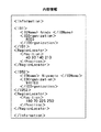
次に取得された内容情報の記述(Description)について述べる。内容情報の記述には、MPEG−7などのマルチメディアコンテンツの記述様式を用いる。本実施の形態では、上記の手順で抽出された選手名および、画像内における表示位置を、内容情報として記述する。例えば、図4に示すように映像中にA(例えば、Anndo),B(例えば、Niyamoto)の2人の選手が含まれている場合には、内容情報の記述形式の一例は図5に示されるようになる。
【0038】
本図において、<Information>は内容情報の開始および終了を示す記述子(タグ)であり、<ID>は個々の選手を識別する記述子であり、この記述子の中には選手の氏名を同定する<IDName>記述子および所属を同定する<IDOrganization>記述子が含まれている。<RegionLocator>記述子は、画像中における選手の表示されている位置を示し、上述の方法によって取得されたものである。<RegionLocator>記述子内にある<Position>記述子に囲まれた値は順に、選手を包含する矩形の左上のX座標、Y座標、右下のX座標、Y座標を表す。なお、画像処理を用いた方法であれば選手を包含する矩形を取得することができるが、計測器(位置センサ・GPS)のみを用いる方法では、不可能である。したがって、計測器のみを用いた場合には、左上座標と右下座標には同一の値、すなわち一点の座標位置が記述される。映像解析部120は、複数台のカメラから入力されたすべての映像に関してそれぞれ上記の内容情報を生成する。また、内容情報はフレームごとに生成されるため、映像と内容情報は1対1に対応する。
【0039】
次に、配信映像マッチング部130、映像情報配信部160および映像受信装置20の映像出力部220に関して説明する。視聴者は、映像情報配信部160を介して映像出力部220に伝送されてくる映像を視聴することができるが、逆に自身の嗜好情報を配信映像マッチング部130に通知することが可能である。スポーツ中継の場合、映像の中心は、競技に出場する選手であり、どの選手が出場するのかは事前に確定している。そこで、本実施の形態では、嗜好度の設定が可能な対象を、競技に出場する選手であるとする。
【0040】
映像解析部120によって各内容情報が生成されると、配信映像マッチング部130は、ライブコンテンツに係る多視点映像とその内容情報とをコンテンツデータベース141に格納する(S13)。
そして、配信映像マッチング部130は、上記テンプレートマッチング法で用いられたテンプレート画像や名前、背番号により嗜好値入力ダイアログ146を生成して、嗜好データベース145に格納した後、コンテンツデータベース141からライブやストレージのいずれかのモード選択するためのモード選択ダイアログ142を読み出して送信する(S14)。映像受信装置20のユーザがモード選択ダイアログ142のスイッチボタンを操作部210のマウスなどによりクリック操作していずれかのモードを指定すると(S15)、いずれのモードが指定されたかを表すモード指定情報が映像受信装置20から映像配信装置10に送信される(S16)。
【0041】
モード指定情報が送信されてくると、配信映像マッチング部130は、ユーザが指定したモードのコンテンツ一覧143をコンテンツデータベース141から読み出して映像受信装置20に送信すると共に(S17)、ライブコンテンツと映像記録部140に格納されたストレージコンテンツとを切換配信するための図示しないスイッチを指定側に切り換える。
【0042】
映像受信装置20のユーザが操作部210のマウスなどに所望のコンテンツをクリック操作してコンテンツを指定すると、映像受信装置20から映像配信装置10にユーザが指定したコンテンツ名が送信される(S18)。
【0043】
コンテンツが指定されると、配信映像マッチング部130は、内容情報に基づき指定されたコンテンツに関する嗜好情報を設定するためのテーブル、嗜好値入力ダイアログ146を嗜好データベース145から読み出し、エディトプログラムなどと共に映像受信装置20に送信する(S19)。この嗜好値入力ダイアログ146は、例えば、エディット画像、スクリプト(氏名、背番号等)からなり、テンプレートマッチング法に用いるテンプレート画像や、氏名、背番号等に基づいて配信映像マッチング部130により生成され、映像記録部140の嗜好データベース145に格納される。なお、この嗜好値入力ダイアログ146の送信は、ライブコンテンツの中継途中であってもよいが、中継が開始される以前の方が好ましい。この理由は、最新の嗜好情報が取得されるまでの間は例えば嗜好履歴テーブル147に格納されている前回行われた同一カードの際に取得した嗜好履歴で映像を選択する方策しかないため、できるだけ早く最新の嗜好で映像を選択した方が、嗜好により合致するからである。
【0044】
図6に、嗜好値入力ダイアログ146のGUIインタフェースの一例を示す。図6のインタフェースは、出場する選手の「顔画像」、「氏名」、「背番号」および、嗜好度を入力する「エディットボックス」(スピンボックス)より構成される。視聴者は、操作部210のリモートコントローラや、キーボードなどのデバイスを用いて、嗜好度を決定したい選手のエディットボックス位置にカーソルを合わせ、嗜好度を入力する。または、エディットボックスの横にある上下の矢印アイコンにカーソルを合わせて、クリックして嗜好度の値を上下させて決定する方法でもよい。本実施の形態では、嗜好度「0」の場合に最も低く、嗜好度「100」の場合に最も高いとする。なお、上述の方法は絶対評価を用いた方法であるが、出場する選手に順序付けを行うなどの相対評価の方法でもよい。以上の方法により取得された嗜好情報は、映像配信装置10に送信される(S20)。図7に嗜好情報の一例を示す。本図に示されるように嗜好情報は、内容情報と同様にMPEG−7などのマルチメディアコンテンツの記述様式を用いて記述されており、個々の選手を識別する記述子<ID>と、この記述子の中には選手の氏名を同定する記述子<IDName>と、嗜好度を同定する記述子<Preference>とが含まれている。この嗜好情報は、映像情報配信部160を介して、配信映像マッチング部130に通知され、嗜好履歴テーブル147に更新記憶される(S21)。
【0045】
嗜好情報を取得すると、配信映像マッチング部130は、映像解析部120より生成された内容情報の付与された複数の映像と、視聴者より通知された嗜好情報やその履歴とに基づき、その視聴者にどの映像を配信するべきかを決定するマッチング処理を実行する(S22)。以下、そのマッチング処理について、2通りの方法(最も嗜好度の高い対象物を利用して決定する方法、個々の嗜好度から総合的に決定する方法)を具体的に説明する。
【0046】
1.最も嗜好度の高い対象物を利用して決定する方法
嗜好度の最も高い選手が表示されている映像を配信する場合には、例えば図8に示されるフローチャートの手順にしたがう。
【0047】
(1)視聴者より通知された嗜好情報を分析し、最も嗜好度の高い選手(以降、配信対象選手とも称す)を決定する(S2201)。
【0048】
(2)映像解析手段より伝送されてきた内容情報を分析し、配信対象選手が写っている映像の数を判断する(S2202)。複数の視点からの映像のうち、(1)で決定された配信対象選手が表示されている映像を配信映像の候補とする。配信対象選手の表示されている映像が1つに限定されている場合には、そのカメラからの映像に決定し(S2203)、この映像を視聴者に配信する。
【0049】
(3)複数の映像に配信対象選手が表示されている場合には、それらの中から、最も適当だと考えられる映像を配信するが、その決定方法は特に限定しない。例えば、内容情報の<RegionLocator>の記述子(Descriptor)で、矩形情報が取得されている場合には(S2204でYes)、配信対象選手を包含している矩形の面積を算出し、最も面積が大きな映像に決定し(S2205)、この映像を配信映像とする。
【0050】
また、矩形情報が取得されていない場合には(S2204でNo)、配信対象選手の表示されている位置を取得し、画面の中心に最も近いものを配信映像とする(S2206)方法が考えられる。なお、配信対象選手が写っている映像の数が「0」の場合には、次番手の選手を決定し、次番手の選手についてステップS2202〜S2206の処理を実行することにより配信映像を決定すればよい(S2207)。
【0051】
2.個々の嗜好度から総合的に決定する方法
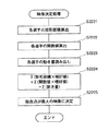
個々の選手の嗜好度に基づき、総合的に判断して配信映像を決定する場合には、例えば図9に示されるフローチャートの手順にしたがう。
【0052】
(1) すべてのカメラからの映像に関して、内容情報の<RegionLocator>の記述子(Descriptor)で矩形情報が取得されているか否か判断する(S2211)。矩形情報が取得されている場合には(S2211でYes)、個々の選手を包含する矩形の面積を算出する(S2212)。矩形情報が取得されていない場合には(S2211でNo)、画面中心で最大値を取り、画面の淵で最小値を取る関数(例えば、f(x,y)=sin(π*x/(2*x_mid))*sin(π*y/(2*y_mid))は上記の条件を満たす。 但し、x、yは画素位置、x_mid、y_midは画面中心の座標であり、*は積を示す。)を規定し、個々の選手の位置を入力して関数の値を求める(S2215)。
【0053】
(2) (1)で求めた値と、対応する選手の嗜好度との積を算出し、さらに画面に表示されている選手の値の総和をとって、当該画像における目的関数の値とする(S2213,S2216)。
【0054】
(3) (2)の値が最大となる視点からの映像を配信映像に決定する(S2214,S2217)。
【0055】
ここで、1フレームごとに上記の処理を行うと、映像が次々に切り替わってしまう可能性があるため、配信映像マッチング部130では、数フレームおきに上記の方法を適用し、視聴者に配信する映像を決定する。
【0056】
以上のようにして配信映像の決定が終わると、配信映像マッチング部130は、決定した映像をストリーム配信する(図2のS23)。そして、映像受信装置20の映像出力部220は、送受信部230を介して配信されてきた映像をその画面上に再生する(図2のS24)。
【0057】
このようにして、実施の形態1に係る映像配信システム1によれば、映像配信装置10において多視点映像の中から各ユーザの嗜好に合致した映像が数フレームごとに選択されて映像受信装置20に配信され、これが映像受信装置20の映像出力部220において再生される。
【0058】
続いて、視聴者は、配信されてくる映像に対して働きかけを行うことにより、付加情報を取得することが可能である(図2のステップS25〜S29)。以下では、例えば、操作部210のマウスのようなポインティングデバイスを用いて付加情報を取得する方法について述べる。
【0059】
例えば、図4に示されるように映像中にA,Bの2人の選手が含まれている場合において、例えば右側の選手B(Niyamoto)の付加情報を取得したいとき、ユーザは、ポインティングデバイスのカーソルを対象B上に合わせてクリックする(図2のS25)。クリックされると、その画面上での位置情報が映像配信装置10の映像情報配信部160を介して配信映像マッチング部130に通知される(図2のS26)。そして、配信映像マッチング部130は、配信映像に付与されている内容情報からどの対象が選択されたのかを特定し、その結果を付加情報提供部150に通知する(図2のS27)。例えば、図4に示される画像が表示されている場合に、右側の画像上の位置がクリックされた場合、配信映像マッチング部130は、図5に示される内容情報に基づいてNiyamotoだけを通知する。付加情報提供部150は、選択された対象であるNiyamotoに関する付加情報を付属情報テーブル151から読み出し、付加情報を配信映像マッチング部130および、映像情報配信部160を介して、映像受信装置20の映像出力部220に送信する(図2のS28)。この付加情報は、図10に示されるように、上記MPEG7にしたがう記述子で記述されており、個々の選手を識別する記述子<ID>と、この記述子の中には選手の氏名を同定する記述子<IDName>と、生年月日を表す記述子<DateOfBirth>と、主な経歴を表す記述子<Career>と、特徴を表す記述子<SpecialAbility>と、選手のコメントを表す記述子<Comment>とが含まれている。
【0060】
なお、選択された対象に関連する情報が記録されていない場合には、情報が存在しないことを通知するメッセージを送信する。
最後に、映像出力部220は、送受信部230を介して配信されてきた付加情報をその画面上に再生する(図2のS29)。
【0061】
このように、実施の形態1に係る映像配信システム1によれば、視聴者は複数の視点から撮影された映像の中から、好みに合致した映像を視聴することができるだけでなく、さらに、配信される映像に働きかけを行うことによって、興味をもっている対象に関連する情報(付加情報)を取得することが可能となる。
【0062】
(実施の形態2)
次いで、本発明の実施の形態2に係る映像配信システムを、図面に基づいて説明する。なお、この実施の形態2においても、限定された空間の撮影対象として、サッカーなどのスポーツ中継の場合の選手を中心とした映像を例に挙げて説明するが、本発明は任意の撮影空間および撮影対象に対して適用可能である。
【0063】
図11は、本発明の実施の形態2における映像配信システム2の機能構成を示すブロック図である。実施の形態1の映像配信システム1と対応する機能構成については同じ番号を付し、その詳細な説明を省略する。
この映像配信システム2は、映像配信装置40と、映像受信装置50と、これらを接続する通信ネットワーク30とから構成され、多視点映像の中からユーザの嗜好に合致した映像を再生するシステムである点で実施の形態1の映像配信システム1と同様であるが、実施の形態1では、映像配信装置10が利用者の嗜好に応じた映像等のコンテンツを決定しストリーム配信したのに対して、この映像配信システム2では、映像配信装置40は多視点映像のコンテンツ等のすべて(選択される可能性のあるすべてのコンテンツ)をストリーム配信しておき、映像受信装置50が利用者の嗜好に応じた映像等を選択決定し再生するようにした点で異なっている。
【0064】
この映像配信システム2の映像配信装置40は、内容情報および付加情報を付加した複数の映像(多視点映像)の映像コンテンツ等を映像受信装置50に向けてストリーム配信するコンピュータ等からなる配信サーバであり、映像取得部110と、映像解析部120と、付加情報提供部410と、映像記録部420と、映像多重化部430と、多重化映像情報配信部440とを備えている。
【0065】
付加情報提供部410は、映像解析部120によって生成された内容情報をサーチし、内容情報に含まれる被写体(対象物)の付加情報を付属情報テーブル151に基づいて生成したり、内容情報および付加情報が付加された映像を映像記録部420のコンテンツデータベース421に格納したり、嗜好値入力ダイアログ146を生成して嗜好データベース145に格納したりする。
【0066】
映像記録部420は、入力側が付加情報提供部410に接続されると共に出力側が映像多重化部430に接続されており、内部にコンテンツデータベース421と、嗜好データベース145とを備えている。コンテンツデータベース421には、内容情報および付加情報が付加された映像コンテンツ424自体が格納される。なお、嗜好データベース145から嗜好履歴テーブル147が削除されている。これは、映像受信装置50において、利用者の嗜好に応じた映像を選択するので、映像配信装置40で嗜好履歴テーブル147を保持しておく必要がないからである。
【0067】
映像多重化部430は、付加情報提供部410から出力される内容情報および付加情報が付加されたライブの多視点映像と、コンテンツデータベース421に格納されたストレージの映像コンテンツ424とをユーザのモード指定に応じて選択し、映像と内容情報と付加情報とをカメラごとに多重化し、さらにそれらの情報を多重化することにより、1つのビットストリームを生成したりする(図13参照)。また、映像多重化部430は、嗜好値入力ダイアログ146を映像受信装置50にストリーム配信したりする。
【0068】
多重化映像情報配信部440は、通信ネットワーク30を介して映像受信装置50と通信するための双方向の通信インタフェースやドライバソフト等である。
【0069】
映像受信装置50は、ライブやストレージのモード選択や、嗜好値の入力等についてユーザと対話したり、映像配信装置40からストリーム配信されてくる映像と内容情報と付加情報とを分離したり、複数の映像(多視点映像)の中からユーザの嗜好や嗜好履歴に合致した1つの映像を数フレームごとに切換・選択するような編集を行った映像コンテンツをリアルタイムに構築し、ユーザに提示したりするパーソナルコンピュータ、携帯電話機、携帯情報端末、デジタル放送用TV等であり、操作部210と、映像出力部220と、送受信部230と、表示映像マッチング部510と、映像記録部520とを備える。
【0070】
表示映像マッチング部510は、映像配信装置40からストリーム配信されてくる映像、内容情報および付加情報をカメラごとに分離し(図13参照)、これらを映像記録部520に格納したり、映像配信装置40から配信されてくる嗜好値入力ダイアログ146を映像記録部520に格納したり、操作部210から送られてきたユーザの嗜好等と映像配信装置40から送られてくる各映像の内容情報とを比較し、複数の映像(多視点映像)の中からユーザの嗜好や嗜好履歴に合致した1つの映像を数フレームごとに切換・選択するような編集を行った映像コンテンツをリアルタイムに構築したりする。
【0071】
映像記録部520は、映像配信装置40から配信されてくるライブあるいはストレージのコンテンツなどを保持するコンテンツデータベース521と、ユーザごとの嗜好を取得するための嗜好データベース525とを保持するハードディスク等である。コンテンツデータベース521は、保持しているストレージコンテンツのコンテンツ一覧523およびコンテンツ524自体を記憶する。また、嗜好データベース525は、映像配信装置40から送られてきたコンテンツごとの嗜好値入力ダイアログ146およびユーザが入力した嗜好履歴を格納する嗜好履歴テーブル147を記憶する。
【0072】
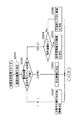
以上のように構成された本実施の形態の映像配信システム2の動作について、図12に示されたシーケンス(本システムの主な処理の流れ)に沿って順に説明する。なお、本図のシーケンスにおいても、ある一時点における多視点映像についての流れを示しており、実施の形態1のシーケンスと対応する処理については、詳細な説明を省略する。
【0073】
映像取得部110による複数の映像(多視点映像)の取得が終わると(S11)、映像解析部120は多視点映像を解析して映像ごとに内容情報を生成し、付加情報提供部410は内容情報をサーチし、内容情報に含まれる被写体(対象物)の付加情報を生成する(S32)。例えば、映像中にA,Bの2人写っている場合には、このA,B2人の付加情報を生成する。付加情報の生成が終わると、付加情報提供部410は、内容情報および付加情報が付加された映像を映像記録部420のコンテンツデータベース421に格納する(S33)。
そして、実施の形態1の場合と同様に、モード選択ダイアログの送信(S14)や、映像受信装置50におけるモード指定(S15)、モード指定情報の送信(S16)、コンテンツ一覧情報の送信(S17)、コンテンツ指定の送信(S18)が順次行われる。
【0074】
コンテンツの指定が行われると、映像多重化部430は、指定されたライブあるいはストレージのコンテンツの多視点映像(複数の映像)と各映像ごとの内容情報と各映像ごとの付加情報とを多重化して送信した後(S39)、このコンテンツの嗜好値入力ダイアログ146を送信する。
【0075】
表示映像マッチング部510は、映像配信装置40から送られてきた多視点映像と各映像ごとの内容情報と各映像ごとの付加情報とを各カメラごとに分離してコンテンツデータベース521に格納し(S40)、さらに嗜好値入力ダイアログ146を嗜好データベース525に格納する。
次いで、表示映像マッチング部510は、嗜好値入力ダイアログ146を嗜好データベース525から読み出して映像出力部220に送り表示させ(S41)、ユーザが入力した嗜好情報を嗜好履歴テーブル147に格納した後(S42)、嗜好情報と内容情報とを比較し、多視点映像の中からユーザの嗜好に合致した1つの視点の映像を決定する(S43)。なお、この映像の決定方法は、本実施の形態1と同様である。そして、表示映像マッチング部510は、決定した映像を映像出力部220に送りその画面上に再生させる(S44)。
【0076】
このように、実施の形態2に係る映像配信システム2によれば、映像配信装置40は複数の映像(多視点映像)を映像受信装置50に送信しておき、映像受信装置50において多視点映像の中からユーザの嗜好に合致した1つの映像が数フレームごとに選択決定され、再生される。
【0077】
続いて、ユーザは、配信されてきた映像に対して働きかけを行うことにより、付加情報を取得することが可能である(図12のステップS45〜S47)。
例えば、ユーザの嗜好に合致した映像が再生され、配信されている映像に付加情報を取得したい対象が表示されている状態において、ユーザが操作部210のポインティングデバイスのカーソルを画面に映し出された対象の上に合わせてクリックすると、その画面上での位置情報が表示映像マッチング部510に通知される(S45)。そして、表示映像マッチング部510は、映像に付与されている内容情報からどの対象が選択されたのかを特定し(S46)、対応する付加情報の中からその特定した付加情報だけを映像出力部220に送る。例えば、図4に示される対象A,Bが表示されている場合に、右側の対象B上の位置がクリックされた場合、表示映像マッチング部510は、まず、図5に示される内容情報に基づいてNiyamotoを特定する。すると、表示映像マッチング部510は、2人についての付加情報の中からNiyamotoに関する付加情報だけを読み出し、映像出力部220に送る。これによって、映像出力部220には、取得したい対象の付加情報だけが表示される(S47)。
【0078】
このように、実施の形態2に係る多視点映像配信システム2によれば、視聴者は複数の視点から撮影された映像の中から、好みに合致した映像を視聴することができるだけでなく、さらに、配信される映像に働きかけを行うことによって、興味をもっている対象に関連する情報(付加情報)を取得することが可能となる。
【0079】
ところで、映像記録部520のコンテンツデータベース521には、映像配信装置40から送られてきた多視点映像と、各映像ごとの内容情報と、各映像ごとの付加情報とがすべて揃ったコンテンツ524が格納されている。したがって、このコンテンツについては、映像配信装置40から再配信を受けるまでもなく、映像受信装置50において、繰り返し再生することができる。
【0080】
また、繰り返し再生の際に、表示映像マッチング部510が、映像記録部520の嗜好データベース525から嗜好値入力ダイアログ146を読み出して、ユーザが入力した前回と異なる嗜好情報に基づいて複数の視点から撮影された映像の中から、この嗜好に合致した映像を再生することもでき、この場合には、ユーザは前回とは異なる対象(選手)を中心とした別の編集の映像を視聴することができる。
【0081】
以上、本発明に係る映像配信システムを実施形態に基づいて説明したが、本発明は実施の形態に限定されるものでなく、以下に述べる変形例についても適用される。
【0082】
上記実施の形態では、映像コンテンツの配信ごとに、嗜好値入力ダイアログ146を表示し、視聴者の嗜好情報を取得するようにしたが、このようなタイミングではなく、嗜好の履歴を用いて多視点映像の中から1つの映像を選択するようにしてもよい。例えば、過去に取得された視聴者の嗜好情報等を映像配信装置40に蓄積しておき、その情報を参照することで、映像コンテンツの配信の度に視聴者から嗜好情報を取得するという手間を省くことができる。
【0083】
また、上記実施の形態1では、付加情報提供部150は、映像受信装置20において位置指定がされた場合にだけ、付加情報が映像配信装置10から映像受信装置20に送信されたが、視聴者の指定を待たずに、配信が決定された映像についての付加情報を映像コンテンツとともにあらかじめ配信しておいてもよい。これによって、視聴者が指示を発してから付加情報を取得するまでの時間が短縮されるので、早い応答性を有する映像配信システムが実現できる。
【0084】
さらに、これとは逆に、上記実施の形態2では、付加情報提供部410が多視点映像のそれぞれについて付加情報が添付されたが、映像受信装置50において位置指定がされた場合にだけ付加情報を配信するようにしてもよい。これによって、最終的に選択されるか否か不明な映像コンテンツの付加情報についても配信しておくことに起因する通信ネットワーク30における通信負荷が軽減される。
【0085】
また、上記実施の形態1,2では、サッカーのライブ中継を例に説明したが、野球等、屋外で行われるスポーツ等のライブ中継や、屋内で行われる音楽会、芝居等のライブ中継にも勿論適用できる。
【0086】
さらに、上記実施の形態1,2では、嗜好のほか、映像中のオブジェクトごとの大きさや、位置だけを映像選択の際における評価の対象としたが、この評価の対象にオブジェクトの動きを加えるようにしてもよい。
【0087】
すなわち、屋内でのライブ中継の場合、この施設にモーションキャプチャシステムを設置することにより、対象(歌手等)がステージ上を走り回るような激しい動きを検出することもできる。一方、例えば、ライブステージでは、複数の被写体が混在する中で主役(注目される人)がリアルタイムに入れ替わるような演出が行われたりする。このような場合、じっとしている人を見るよりは、その時点でステージ上を走り回っているような激しい動きをしている人(活躍している人)を見たいというのが、視聴者の心理であり、嗜好に合致する。したがって、モーションキャプチャシステムの機器を用いて得られる映像中で表示されている対象の動き量を映像解析部120で解析し、動き量を内容情報に含め、動きの激しい被写体ほど、注目度や、関心度が高いとして、この映像を選択するようにしてもよい。
【0088】
(実施の形態3)
図14は、あるグループ「スペード」のライブコンサートのステージの様子を示す図である。
同図に示されるように、ステージの周囲には、複数台(図示、4台)のカメラC1〜C4が固定配設され、スペードのメンバー(図14の左から古垣、下原、前井、陸袋)の肢体には、複数のマーカMがそれぞれ取着されている。
【0089】
各カメラC1〜C4は、R,G,Bの各色画像を取得するほか、赤外光を射出する発光部と、マーカMで反射された赤外光を受光する受光部とを備えており、フレームごとにマーカで反射された映像を受光部で取り込むように構成されている。このフレームごとのマーカ映像は、例えば図1に示される映像解析部120に送られて、対象の動き量が解析される。
【0090】
図15は、2つのマーカ画像(P1,P2)から動き量を解析する様子を示す図である。なお、ここでは、図14に示されるメンバー下原だけが映っている2つのマーカ画像から動き量を解析する場合が示されている。
【0091】
映像解析部120は、2つのマーカ画像P1,P2の対応する各マーカMを比較し、肩、肘、手首、…、足先といった各部分の動き量Δv1,Δv2,Δv3,Δv4,…Δv(n−1),Δvnをそれぞれ計測する。そして、映像解析部120は、各部分の計測が終わると、これらの計測値の総和を計算し、この計算結果をその時点における映像中で表示されている対象、歌手の動き量として取得し、取得した動き量を内容情報に含める。なお、まず腰、肩等を基準にして、腕、手首、といった順番で動き量を計算してもよい。また、複数の視点から得られたマーカ画像Mを組み合わせ、3次元の動きベクトルを計測してもよい。この場合には、1つのマーカ画像Mでマーカが重なるような場合でも、各マーカを峻別することができ、動き量の誤計算といった事態を避けることができ、精度の高い動き量を求めることが出きる。
【0092】
図16は、映像解析部120により生成される内容情報の一例を示す図である。
この例では、<RegionLocator>記述子に、画像中における歌手の表示されている大きさを有する位置<Position>と、計測器(位置センサ・GPS)等によって取得された大きさを有さないポイントの位置<Location>とが合わせて記述されており、対象の画面上の大きさと、中央等の位置と両者でオブジェクト単位での評価を行うことができるようになっている。さらに、この内容情報では、<motion>記述子により、動き量についてオブジェクト単位での評価を行うことができるようになっている。
【0093】
このように内容情報がオブジェクトの大きさ、位置のほか、動き量が含められて構成されている場合、個々の歌手の嗜好度や、画面上における対象の大きさ、位置、動き等に基づき、個々の対象をオブジェクトごとに評価し、総合的に判断して配信映像を決定する場合には、例えば図17に示されるフローチャートの手順にしたがう。
【0094】
配信映像マッチング部130は、まず、すべてのカメラからの映像に関して、内容情報の<RegionLocator>の記述子(Descriptor)で矩形情報を参照し、個々のオブジェクト、歌手を包含する矩形の面積を算出する(S2221)。矩形面積の算出が終わると、配信映像マッチング部130は、画面中心で最大値を取り、画面の淵で最小値を取る関数(例えば、f(x,y)=sin(π*x/(2*x_mid))*sin(π*y/(2*y_mid))を用いて、個々の歌手の位置に関する関数の値を算出する(S2222)。関数値の値の算出が終わると、配信映像マッチング部130は、すべてのカメラからの映像に関して、内容情報の<motion>記述子を参照し、動き量を読み出す(S2223)。
【0095】
面積の算出、関数値の算出、動き量の読み出しが終わると、配信映像マッチング部130は、すべてのカメラからの映像に関して、面積と対応する歌手の嗜好度との積を算出し、さらに画面に表示されている歌手の値の総和を算出し、位置とこの位置に対応する歌手の嗜好度との積を算出し、さらに画面に表示されている歌手の値の総和を算出し、さらに画面に表示されている歌手の動き量の値の総和を算出することにより、目的関数の値を求める(S2224)。
そして、すべてのカメラからの映像に関して、目的関数の値を求めると、目的関数の値が最大となる視点からの映像を配信映像に決定する(S2225)。
【0096】
このようにして、動き量を評価値の中に含めると、じっとしているよりも活躍しているであろう動きの多い歌手の映像が高く評価され、高く評価された映像が数フレームごとに選択されることにないる。この結果、映像配信装置10において多視点映像の中から各ユーザの嗜好に合致した映像が配信されることになる。
【0097】
【発明の効果】
以上の説明から明らかなように、本発明に係る映像配信装置は、通信ネットワークを介して映像受信装置と通信する映像配信装置であって、異なる視点からの複数の映像を取得する映像取得手段と、前記映像ごとに、その映像に含まれる内容を解析し、解析結果を内容情報として生成する映像解析手段と、前記各内容情報と、視聴者より通知された嗜好情報との適合度を判定し、配信する映像を決定し、決定した映像を配信する配信映像マッチング手段とを備えることを特徴とする。
つまり、異なる視点からの複数の映像の中から各映像ごとに生成された内容情報と視聴者の嗜好情報との適合度で決定し、視聴者の嗜好に合致した1つの映像を視聴者の映像受信装置に対して配信する。
【0098】
これにより、視聴者は、自己の嗜好に合致した映像を選択的に視聴することができる。したがって、映像の選択に関して視聴者の要求を満足させることができる。しかも、映像取得手段、映像解析手段および配信映像マッチング手段による処理を高速に繰り返して行うことで、リアルタイム映像に関しても配信の対象とすることができる。
【0099】
ここで、内容情報には、被写体を同定する情報や、被写体の表示位置または表示領域を表す情報を含めてもよい。また、嗜好情報を得るための入れ物を映像受信装置側に配信し、この入れ物に被写体に対する嗜好の度合いを入力させることにより嗜好情報を取得してもよい。また、配信した映像について視聴者から画面上の位置が指定されると、その位置の被写体を特定し、この被写体に関する付加情報を送信するようにしてもよい。
【0100】
さらに、本発明は、通信ネットワークを介して映像受信装置と通信する映像配信装置であって、異なる視点からの複数の映像を取得する映像取得手段と、前記映像ごとに、その映像に含まれる内容を解析し、解析結果を内容情報として生成する映像解析手段と、前記各映像および前記各内容情報を多重化して配信する映像多重化手段とを備えることを特徴とする映像配信装置とすることもできる。この場合には、映像受信装置の側において映像配信装置から配信されてきた各内容情報と、視聴者より通知された嗜好情報との適合度を判定し、映像配信装置から配信されてきた複数の映像の中から再生する1つの映像を決定し、決定した映像を再生するようにすればよい。
【0101】
これによって、このような映像配信装置から配信した各映像および各内容情報を受信する映像受信装置において、各内容情報と視聴者より通知された嗜好情報との適合度を判定し、再生する映像を決定し、決定した映像を再生することにすれば、視聴者は、自己の嗜好に合致した映像を選択的に視聴することができる。
【0102】
また、本発明は、このような特徴的な手段をコンピュータに機能させるプログラムとして実現したり、そのプログラムを記録した記録媒体として実現したりすることもできる。そして、本発明に係るプログラムをインターネット等の通信網や記録媒体等を介して流通させることもできる。
【0103】
このように、本発明により、視聴者は、例えば、スポーツ観戦の番組において、自分がひいきにしている選手が頻繁に登場する映像を選択的に視聴することができ、楽しい時間を過ごすことができる。よって、本発明は、映像配信システムが提供するサービスの価値を飛躍的に向上させるものであり、その実用的価値は極めて高い。
【図面の簡単な説明】
【図1】本発明の実施の形態1における映像配信システム1の機能構成を示すブロック図である。
【図2】映像配信システム1の動作を示すシーケンス図である。
【図3】図3(a)は本発明の実施の形態1で用いるカメラ座標系における位置と、投影面上における位置の関係を示す斜視図であり、図3(b)は図3(a)を投影面に沿って上方から見た図であり、図3(c)は図3(a)を投影面に沿って側方から見た図である。
【図4】図1に示される映像取得部110により取得された映像の一例を示す図である。
【図5】図1に示される映像解析部120により生成される内容情報の一例を示す図である。
【図6】図1に示される配信映像マッチング部130により生成される嗜好値入力ダイアログの一例を示す図である。
【図7】図1に示される映像受信装置20から送られてくる嗜好情報の一例を示す図である。
【図8】配信映像マッチング部130が最も嗜好度が高い対象物を利用して配信する映像を決定する際に実行するフローチャートである。
【図9】配信映像マッチング部130が個々の嗜好度から総合的に判断して配信する映像を決定する際に実行するフローチャートである。
【図10】図1に示される付加情報提供部150から送られる付加情報の一例を示す図である。
【図11】本発明の実施の形態2における映像配信システム2の機能構成を示すブロック図である。
【図12】映像配信システム2の動作を示すシーケンス図である。
【図13】映像、内容情報および付加情報の多重化・分離方法の一例を示す図である。
【図14】、あるグループ「スペード」のライブコンサートのステージの様子を示す図である。
【図15】2つのマーカ画像(P1,P2)から動き量を解析する様子を示す図である。
【図16】映像解析部120により生成される内容情報の一例を示す図である。
【図17】配信映像マッチング部130が個々の嗜好度等から総合的に判断して配信する映像を決定する際に実行するフローチャートである。
【符号の説明】
1,2 映像配信システム
10,40 映像配信装置
20,50 映像受信装置
30 通信ネットワーク
110 映像取得部
120 映像解析部
130 配信映像マッチング部
140,420,520 映像記録部
141,421,521 コンテンツデータベース
144,424,524 コンテンツ
145,525 嗜好データベース
146 嗜好値入力ダイアログ
147 嗜好履歴テーブル
150,410 付加情報提供部
210 操作部
220 映像出力部
230 送受信部
430 映像多重化部
440 多重化映像情報配信部
510 表示映像マッチング部[0001]
BACKGROUND OF THE INVENTION
The present invention relates to a video distribution device and a video reception device that distribute or receive a video such as a sports program.
[0002]
[Prior art]
With the advancement of communication network infrastructure, technologies related to the distribution and reception of sports programs and other images are being developed. As conventional techniques relating to such video distribution and reception, a video information distribution system disclosed in JP-A-7-95322 (first publication) and JP-A-2-54646 (second publication) are disclosed. There is a disclosed program distribution device.
[0003]
The video information distribution system disclosed in the first publication includes a video center, a video dial tone trunk, and a user terminal. When the user calls the video center, a program desired by the user is transmitted from the video center via a transmission path. The video dial tone trunk receives video information transferred at high speed from the video center, reproduces it into normal speed video information, and transmits it to the user terminal via a low-speed transmission path.
[0004]
The program distribution device disclosed in the second publication receives a program distribution request and an advertisement insertion request from a terminal device via a network, a storage device that holds a plurality of moving image programs, and a moving image program and a designated advertisement. It comprises a distribution device that divides a request into information blocks and distributes it via a network, and a control device that controls charging to differ according to the timing at which the advertisement specified in the advertisement insertion request described above is inserted.
[0005]
[Problems to be solved by the invention]
However, in the above-described conventional technology, the video delivered to the viewer is a video shot only from the creator's intention from a specific viewpoint, and the viewer can watch the video according to his / her preference. An operation such as changing the viewpoint is impossible. For example, in a sports watching program such as a soccer game, even if the viewer has a request to watch a specific player he / she likes, only the other players appear in only a few scenes. Even video works that appear, I have to watch this.
[0006]
In addition, the above-described conventional technique has a problem in that a program must be recorded in advance in a video center or a storage device, and a mechanism for distributing real-time video is not provided.
Therefore, the present invention has been made in view of such a situation, and an object thereof is to provide a video distribution device and a video reception device capable of distributing a video reflecting viewer's preference.
[0007]
It is another object of the present invention to provide a video distribution apparatus and a video reception apparatus capable of not only distributing stored video but also distributing real-time (live) video reflecting viewers' preferences. And
[0008]
[Means for Solving the Problems]
In order to achieve the above object, a video distribution apparatus according to the present invention is a video distribution apparatus that communicates with a video reception apparatus via a communication network, and a video acquisition unit that acquires a plurality of videos from different viewpoints; For each video, analyze the content included in the video, determine the degree of fit between the video analysis means for generating the analysis result as content information, each content information, and the preference information notified from the viewer, It comprises distribution video matching means for determining a video to be distributed and distributing the determined video. In other words, it is determined by the degree of matching between the content information generated for each video from a plurality of videos from different viewpoints and the viewer's preference information, and one video that matches the viewer's preference is selected as the viewer's video. Deliver to the receiving device.
[0009]
Here, the content information may include information for identifying the subject and information indicating the display position or display area of the subject. Alternatively, the container for obtaining the preference information may be distributed to the video receiving device side, and the preference information may be acquired by causing the container to input the degree of preference for the subject. Further, when a position on the screen is designated by the viewer for the distributed video, the subject at that position may be specified, and additional information regarding this subject may be transmitted.
[0010]
Furthermore, the present invention is a video distribution device that communicates with a video receiving device via a communication network, and includes video acquisition means for acquiring a plurality of videos from different viewpoints, and contents included in the videos for each of the videos A video distribution device comprising: a video analysis unit that analyzes the video and generates an analysis result as content information; and a video multiplexing unit that multiplexes and distributes each video and each content information. it can. In this case, the degree of matching between each content information distributed from the video distribution device on the video reception device side and the preference information notified from the viewer is determined, and a plurality of distribution information distributed from the video distribution device is determined. One video to be played back may be determined from the video and the determined video may be played back.
[0011]
In addition, the present invention can be realized as a program for causing a computer to function such characteristic means, or as a recording medium on which the program is recorded. The program according to the present invention can be distributed via a communication network such as the Internet, a recording medium, or the like.
[0012]
DETAILED DESCRIPTION OF THE INVENTION
(Embodiment 1)
Hereinafter, a video distribution system according to
[0013]
FIG. 1 is a block diagram showing a functional configuration of a
The
[0014]
The
[0015]
The
[0016]
The
[0017]
The distribution
[0018]
The
[0019]
The additional
[0020]
The video
[0021]
The
[0022]
The
[0023]
The transmission /
[0024]
The
[0025]
The operation of the
[0026]
The
[0027]
The
[0028]
1. Method using measuring instrument
In the method using a measuring instrument, a three-dimensional position in a coordinate system (hereinafter referred to as a global coordinate system) with an arbitrary point in space as a reference point can be measured, and a position sensor assigned with a unique ID number (For example, GPS, hereinafter referred to as a position sensor) is attached to each object to be identified. As a result, each object can be identified and a three-dimensional position can be acquired. Next, cameras for acquiring images are installed at various positions and angles.
[0029]
In the first embodiment, the installed camera is fixed, and panning and tilting are not performed. Therefore, it is necessary to prepare a camera that can cover the entire shooting space in a fixed state. For all cameras for which fixed positions have been determined, the position in the global coordinate system and the line-of-sight (collimation) direction vector are obtained and notified to the
[0030]
Next, a method for identifying the position on the video (on the screen) where the object is displayed using the information from the position sensor and the position information of the camera will be described.
First, the three-dimensional position coordinates of the position sensor in the global coordinate system are converted into an expression in the camera coordinate system. Assuming that the matrix for converting the global coordinate system to the camera coordinate system of the i-th camera is Mvi and the output of the position sensor in the global coordinate system is vw, the output (coordinate) vc of the position sensor in the camera coordinate system is vc = Mvi · It is calculated by vw. Here, “·” represents a product of a matrix and a vector. Moreover, this expression is expressed as follows using matrix and vector components.
[Expression 1]
Next, the two-dimensional coordinates of the position sensor on the projection plane of the camera are obtained by using projection transformation. The coordinates on the projection plane are shown in FIG. 3 (b) when FIG. 3 (a) is viewed from above along the projection plane and FIG. 3 (c) when FIG. 3 (a) is viewed from the side along the projection plane. vp = (xp, yp) becomes xp = xc / (zc / d) and yp = yc / (zc / d). Then, it is determined whether or not the calculated xp and yp are within the projection plane (screen) of the camera, and if so, the coordinates are acquired as the display position. By applying the above processing to all cameras and all objects, it is determined which object is currently displayed at which position for each camera.
[0032]
2. Method using image processing
In the method using image processing, content information is extracted from only the video acquired from the camera without using a position sensor or the like, so that the camera does not need to be fixed as in the case of using a measuring instrument. In order to identify an object from an image, it is necessary to cut out only the object from the image and further identify the object. Although there is no particular limitation on the method of extracting the target object from the video, the background is basically a single color in the above-described example of the sports broadcast (for example, the background is a lawn color for soccer or American football relay) Therefore, it is possible to separate the background and the object using color information. Below, the technique for identifying the some target object extracted from the image | video is described.
[0033]
(1) Template matching
For each player, a number of template images are prepared, the object separated from the background is matched with the template image, and the player is identified from the image considered to be the best match. Specifically, first, paying attention to a certain player included in the video, a minimum rectangle (hereinafter referred to as “target rectangle”) surrounding the player is obtained. Next, for a certain template (assumed to be a rectangle), the size of the rectangle is adjusted by down-sampling when the template is larger than the target rectangle and up-sampling when the template is smaller. Then, the difference between the pixel value at a certain position of the target rectangle and the pixel value at the same position as that of the template image is taken. The above processing is performed for all the pixels, and the sum S thereof is calculated. It is assumed that the above-described processing is performed for all template images, and the player of the template image having the smallest S is the player to be identified.
[0034]
(2) Motion prediction
In sports broadcast video, the movement of the player is continuous, so there is no dramatic change between frames. In addition, since the moving direction and speed are also limited, if the position of the player in the current frame is known, the position in the next frame can be predicted to some extent. Therefore, it is possible to predict a range of possible values of the position of the player in the next frame from the position of the player in the current frame, and use template matching only for that range. Moreover, since the positional relationship with the players around the player of interest does not change dramatically, it can be used as information for motion prediction. For example, if the position in the current frame of the player displayed next to the image one frame before is known, the player who is the object of identification is likely to exist in the vicinity, and the position in the current frame Can be predicted.
[0035]
(3) Use of pre-acquired information
In the case of sports broadcasts, the opposing teams often wear different colored uniforms. Since the color of the uniform can be acquired in advance, the team can be identified using the color information. In addition, the uniform is given a back number, and the back number is not used redundantly, which is very effective in identifying individual players.
[0036]
The identification of the object and the acquisition of the position where the object is displayed are achieved by combining the above-described methods. For example, the team is discriminated by first matching the color information of the object with the color information of the uniform. Next, a large number of template images obtained by cutting out only the uniform number portion of the uniform are prepared, and the identification number is identified using template matching. The identification is completed for the player who can identify the player's number. For a player who could not be identified, a motion prediction is performed using the image of the previous frame and the positional relationship with surrounding players that have already been identified, and a template with the whole body image of the player as a template image for the predicted range Perform matching. The position is specified by an upper left position and a lower right position of the target rectangle in the main scanning direction and the sub scanning direction.
[0037]
Next, description (Description) of the acquired content information will be described. For the description of the content information, a description format of multimedia contents such as MPEG-7 is used. In the present embodiment, the player name extracted by the above procedure and the display position in the image are described as content information. For example, as shown in FIG. 4, when two players A (for example, Anno) and B (for example, Niyamato) are included in the video, an example of the description format of the content information is shown in FIG. It comes to be.
[0038]
In this figure, <Information> is a descriptor (tag) indicating the start and end of the content information, and <ID> is a descriptor that identifies each player. In this descriptor, the player's name is displayed. An <IDName> descriptor for identifying and an <IDOrganization> descriptor for identifying affiliation are included. The <RegionLocator> descriptor indicates the position where the player is displayed in the image, and is acquired by the above-described method. The values enclosed in the <Position> descriptor in the <RegionLocator> descriptor sequentially represent the upper left X coordinate, the Y coordinate, the lower right X coordinate, and the Y coordinate of the rectangle including the player. Note that a rectangle including a player can be acquired by a method using image processing, but it is not possible by a method using only a measuring instrument (position sensor / GPS). Therefore, when only the measuring instrument is used, the same value, that is, the coordinate position of one point is described in the upper left coordinate and the lower right coordinate. The
[0039]
Next, the distribution
[0040]
When each content information is generated by the
The distribution
[0041]
When the mode designation information is transmitted, the distribution
[0042]
When the user of the
[0043]
When the content is specified, the distribution
[0044]
FIG. 6 shows an example of the GUI interface of the preference
[0045]
When the preference information is acquired, the distribution
[0046]
1. How to make the decision using the object with the highest preference
When distributing a video in which a player with the highest preference is displayed, for example, the procedure of the flowchart shown in FIG. 8 is followed.
[0047]
(1) The preference information notified from the viewer is analyzed, and the player with the highest preference level (hereinafter also referred to as a distribution target player) is determined (S2201).
[0048]
(2) The content information transmitted from the video analysis means is analyzed to determine the number of videos in which the distribution target player is shown (S2202). Among videos from a plurality of viewpoints, a video displaying the distribution target player determined in (1) is set as a distribution video candidate. If the distribution target player's displayed video is limited to one, the video from the camera is determined (S2203), and this video is distributed to the viewer.
[0049]
(3) When a distribution target player is displayed on a plurality of videos, a video considered to be most appropriate among them is distributed, but the determination method is not particularly limited. For example, when the rectangle information is acquired in the <RegionLocator> descriptor (Descriptor) of the content information (Yes in S2204), the area of the rectangle including the distribution target player is calculated, and the area is the largest. A large video is determined (S2205), and this video is used as a distribution video.
[0050]
If rectangular information has not been acquired (No in S2204), the position where the distribution target player is displayed is acquired, and the one closest to the center of the screen is set as the distribution video (S2206). . If the number of videos in which the distribution target player is shown is “0”, the next player is determined, and the distribution video is determined by executing the processing of steps S2202 to S2206 for the next player. (S2207).
[0051]
2. A method for comprehensive determination from individual preference levels
When determining the distribution video based on the overall preference based on the preference level of each player, for example, the procedure of the flowchart shown in FIG. 9 is followed.
[0052]
(1) It is determined whether or not rectangular information has been acquired for all video images from the <RegionLocator> descriptor (Descriptor) of the content information (S2211). If the rectangle information has been acquired (Yes in S2211), the area of the rectangle including each player is calculated (S2212). If rectangular information has not been acquired (No in S2211), a function that takes the maximum value at the center of the screen and takes the minimum value at the edge of the screen (for example, f (x, y) = sin (π * x / ( 2 * x_mid)) * sin (π * y / (2 * y_mid)) satisfies the above conditions, where x and y are pixel positions, x_mid and y_mid are coordinates of the screen center, and * indicates a product. .) And the position of each player is input to obtain the value of the function (S2215).
[0053]
(2) The product of the value obtained in (1) and the preference level of the corresponding player is calculated, and the sum of the player values displayed on the screen is taken as the value of the objective function in the image. (S2213, S2216).
[0054]
(3) The video from the viewpoint that maximizes the value of (2) is determined as the distribution video (S2214, S2217).
[0055]
Here, if the above processing is performed for each frame, there is a possibility that videos are switched one after another. Therefore, the distribution
[0056]
When the determination of the distribution video is completed as described above, the distribution
[0057]
In this way, according to the
[0058]
Subsequently, the viewer can acquire additional information by acting on the distributed video (steps S25 to S29 in FIG. 2). Hereinafter, for example, a method of acquiring additional information using a pointing device such as a mouse of the
[0059]
For example, when two players A and B are included in the video as shown in FIG. 4, for example, when the user wants to acquire additional information of the right player B (Niyamamoto), the user Place the cursor on the target B and click (S25 in FIG. 2). When clicked, position information on the screen is notified to the distribution
[0060]
In addition, when the information relevant to the selected object is not recorded, a message notifying that there is no information is transmitted.
Finally, the
[0061]
As described above, according to the
[0062]
(Embodiment 2)
Next, a video distribution system according to
[0063]
FIG. 11 is a block diagram showing a functional configuration of the
This
[0064]
The
[0065]
The additional
[0066]
The
[0067]
The
[0068]
The multiplexed video
[0069]
The
[0070]
The display
[0071]
The video recording unit 520 is a hard disk or the like that holds a content database 521 that holds live or storage content delivered from the
[0072]
The operation of the
[0073]
When the
As in the case of the first embodiment, the mode selection dialog is transmitted (S14), the mode designation (S15) in the
[0074]
When the content is specified, the
[0075]
The display
Next, the display
[0076]
As described above, according to the
[0077]
Subsequently, the user can acquire additional information by acting on the distributed video (steps S45 to S47 in FIG. 12).
For example, in a state where a video that matches the user's preference is played and the target for which additional information is to be acquired is displayed in the distributed video, the user has displayed the pointing device cursor of the
[0078]
As described above, according to the multi-view
[0079]
By the way, the content database 521 of the video recording unit 520 stores content 524 in which all of the multi-view video transmitted from the
[0080]
Also, during repeated playback, the display
[0081]
As described above, the video distribution system according to the present invention has been described based on the embodiment. However, the present invention is not limited to the embodiment, and may be applied to modifications described below.
[0082]
In the above-described embodiment, the preference
[0083]
In the first embodiment, the additional
[0084]
Further, on the contrary, in the second embodiment, the additional
[0085]
In the first and second embodiments, the live broadcast of soccer has been described as an example. However, the live broadcast of sports such as baseball and the like performed outdoors, and the live broadcast of concerts and plays performed indoors, etc. Of course, it can be applied.
[0086]
Furthermore, in the first and second embodiments, in addition to the preference, only the size and position of each object in the video are set as the evaluation targets when selecting the video, but the movement of the object is added to the evaluation target. It may be.
[0087]
That is, in the case of live broadcast indoors, by installing a motion capture system in this facility, it is also possible to detect a violent movement in which an object (such as a singer) runs on the stage. On the other hand, for example, in a live stage, there is an effect in which the leading role (person to be noticed) is switched in real time while a plurality of subjects are mixed. In this case, the viewer wants to see the person (the person who is active) who is moving on the stage at that time rather than watching the person who is still standing. It is psychological and matches taste. Therefore, the amount of movement of the target displayed in the video obtained using the motion capture system device is analyzed by the
[0088]
(Embodiment 3)
FIG. 14 is a diagram illustrating a state of a live concert stage of a certain group “SPADE”.
As shown in the figure, a plurality of (four shown) cameras C1 to C4 are fixedly arranged around the stage, and members of spades (from the left in FIG. 14, Furugaki, Shimohara, Maei). A plurality of markers M are respectively attached to the limbs.
[0089]
Each of the cameras C1 to C4 includes R, G, and B color images, a light emitting unit that emits infrared light, and a light receiving unit that receives the infrared light reflected by the marker M. An image reflected by the marker for each frame is captured by the light receiving unit. The marker video for each frame is sent to, for example, the
[0090]
FIG. 15 is a diagram illustrating a state in which a motion amount is analyzed from two marker images (P1, P2). Here, a case is shown in which the amount of motion is analyzed from two marker images in which only the member Shimohara shown in FIG. 14 is shown.
[0091]
The
[0092]
FIG. 16 is a diagram illustrating an example of content information generated by the
In this example, the <RegionLocator> descriptor has a position <Position> having the size displayed by the singer in the image, and a point that does not have the size acquired by a measuring instrument (position sensor / GPS) or the like. The position <Location> is described together, and the evaluation on the object unit can be performed on both the size on the target screen and the position such as the center. Furthermore, in this content information, the motion amount can be evaluated in object units by the <motion> descriptor.
[0093]
In this way, when the content information is configured to include the amount of movement in addition to the size and position of the object, based on the preference level of each singer, the size, position, movement, etc. of the target on the screen, When each object is evaluated for each object and the distribution video is determined by comprehensive judgment, for example, the procedure of the flowchart shown in FIG. 17 is followed.
[0094]
First, the distribution
[0095]
When the calculation of the area, the calculation of the function value, and the reading of the motion amount are finished, the distribution
Then, when the value of the objective function is obtained for the videos from all cameras, the video from the viewpoint that maximizes the value of the objective function is determined as the distribution video (S2225).
[0096]
In this way, when the amount of movement is included in the evaluation value, the video of a singer with a lot of movement that will be active rather than still is highly evaluated, and the highly evaluated video is evaluated every few frames. Will be selected. As a result, the
[0097]
【The invention's effect】
As is apparent from the above description, the video distribution apparatus according to the present invention is a video distribution apparatus that communicates with a video reception apparatus via a communication network, and a video acquisition unit that acquires a plurality of videos from different viewpoints. For each video, the content included in the video is analyzed, and the degree of conformity between the video analysis means for generating the analysis result as content information, the content information, and the preference information notified from the viewer is determined. And a distribution video matching means for determining a video to be distributed and distributing the determined video.
In other words, it is determined by the degree of matching between the content information generated for each video from a plurality of videos from different viewpoints and the viewer's preference information, and one video that matches the viewer's preference is selected as the viewer's video. Deliver to the receiving device.
[0098]
Thereby, the viewer can selectively view the video that matches his / her preference. Therefore, it is possible to satisfy the viewer's request regarding the selection of video. In addition, real-time video can be targeted for distribution by repeatedly performing the processing by the video acquisition unit, the video analysis unit, and the distribution video matching unit at high speed.
[0099]
Here, the content information may include information for identifying the subject and information indicating the display position or display area of the subject. Alternatively, the container for obtaining the preference information may be distributed to the video receiving device side, and the preference information may be acquired by causing the container to input the degree of preference for the subject. Further, when a position on the screen is designated by the viewer for the distributed video, the subject at that position may be specified, and additional information regarding this subject may be transmitted.
[0100]
Furthermore, the present invention is a video distribution device that communicates with a video receiving device via a communication network, and includes video acquisition means for acquiring a plurality of videos from different viewpoints, and contents included in the videos for each of the videos A video distribution device comprising: a video analysis unit that analyzes the video and generates an analysis result as content information; and a video multiplexing unit that multiplexes and distributes each video and each content information. it can. In this case, the degree of matching between each content information distributed from the video distribution device on the video reception device side and the preference information notified from the viewer is determined, and a plurality of distribution information distributed from the video distribution device is determined. One video to be played back may be determined from the video and the determined video may be played back.
[0101]
Thus, in a video receiving device that receives each video and each content information distributed from such a video distribution device, the degree of matching between each content information and the preference information notified from the viewer is determined, and the video to be played back is determined. If it is determined and the determined video is reproduced, the viewer can selectively view the video that matches his / her preference.
[0102]
In addition, the present invention can be realized as a program for causing a computer to function such characteristic means, or as a recording medium on which the program is recorded. The program according to the present invention can be distributed via a communication network such as the Internet, a recording medium, or the like.
[0103]
Thus, according to the present invention, for example, in a sports watching program, viewers can selectively watch videos in which the players he / she likes frequently appear and have a good time. . Therefore, the present invention dramatically improves the value of the service provided by the video distribution system, and its practical value is extremely high.
[Brief description of the drawings]
FIG. 1 is a block diagram showing a functional configuration of a
FIG. 2 is a sequence diagram showing an operation of the
3A is a perspective view showing the relationship between the position in the camera coordinate system used in the first embodiment of the present invention and the position on the projection plane, and FIG. 3B is a perspective view of FIG. ) Is viewed from above along the projection plane, and FIG. 3C is a view of FIG. 3A viewed from the side along the projection plane.
4 is a diagram illustrating an example of an image acquired by the
5 is a diagram showing an example of content information generated by the
6 is a diagram illustrating an example of a preference value input dialog generated by a distribution
7 is a diagram showing an example of preference information sent from the
FIG. 8 is a flowchart executed when the distribution
FIG. 9 is a flowchart executed when the distribution
10 is a diagram showing an example of additional information sent from the additional
FIG. 11 is a block diagram showing a functional configuration of a
12 is a sequence diagram showing an operation of the
FIG. 13 is a diagram illustrating an example of a method for multiplexing / separating video, content information, and additional information.
FIG. 14 is a view showing a state of a live concert stage of a certain group “SPADE”.
FIG. 15 is a diagram illustrating a state in which a motion amount is analyzed from two marker images (P1, P2).
16 is a diagram illustrating an example of content information generated by the
FIG. 17 is a flowchart executed when the distribution
[Explanation of symbols]
1, 2 Video distribution system
10, 40 Video distribution device
20, 50 video receiver
30 Communication network
110 Video acquisition unit
120 Video analysis unit
130 Distribution video matching section
140, 420, 520 Video recording unit
141,421,521 Content Database
144,424,524 content
145,525 preference database
146 Preference value input dialog
147 Preference history table
150,410 Additional information provider
210 Operation unit
220 Video output unit
230 Transceiver
430 Video multiplexing unit
440 Multiplexed video information distribution unit
510 Display image matching unit
Claims (5)
異なる視点からの複数の映像を取得する映像取得手段と、
前記映像ごとに前記映像に含まれる被写体を解析し、前記被写体を包含する矩形に関する情報である矩形情報を含む内容情報を、前記映像毎に、生成する映像解析手段と、
前記被写体に対する視聴者の好みの度合いを示す値である嗜好度を含む嗜好情報を記憶する記憶手段と、
前記被写体に対応する矩形情報から前記矩形の面積を求め、前記矩形の面積と前記嗜好度とを掛け合わせた値を前記被写体と前記視聴者の嗜好との適合度とし、前記被写体の適合度を用いて、前記被写体を含む映像と前記視聴者の嗜好との適合度を求め、さらに、前記映像の適合度を用いて、前記複数の映像の中から前記視聴者との適合度が高い映像を決定し、配信する配信映像マッチング手段と
を備えることを特徴とする映像配信装置。A video distribution device for distributing video via a communication network,
Video acquisition means for acquiring a plurality of videos from different viewpoints;
Analyzing the subject included in the image for each of the video, the content information including rectangle information is information about a rectangle encompassing the object, for each of the video, a video analysis unit configured to generate,
Storage means for storing preference information including a preference level that is a value indicating a degree of preference of the viewer with respect to the subject;
The rectangular area is obtained from the rectangular information corresponding to the subject, and a value obtained by multiplying the rectangular area by the preference level is set as the matching level between the subject and the viewer's preference, and the matching level of the subject is determined. Using the video including the subject and the viewer's preference, and further using the video compatibility to select a video having a high fitness with the viewer from the plurality of videos. A video distribution device comprising: distribution video matching means for determining and distributing.
前記配信映像マッチング手段は、前記複数の映像の中から選択して決定した映像に対応する付加情報を前記付加情報記憶手段から読み出し、当該映像とともに配信する
ことを特徴とする請求項1記載の映像配信装置。The video distribution device further includes additional information storage means for storing in advance additional information corresponding to each of the plurality of videos,
The video according to claim 1, wherein the distribution video matching means reads additional information corresponding to a video selected and determined from the plurality of videos from the additional information storage means and distributes the additional information together with the video. Distribution device.
異なる視点からの複数の映像を取得する映像取得ステップと、
前記映像ごとに前記映像に含まれる被写体を解析し、前記被写体を包含する矩形に関する情報である矩形情報を含む内容情報を、前記映像毎に、生成する映像解析ステップと、
前記被写体に対する視聴者の好みの度合いを示す値である嗜好度を含む嗜好情報を記憶する記憶ステップと、
前記被写体に対応する矩形情報から前記矩形の面積を求め、前記矩形の面積と前記嗜好度とを掛け合わせた値を前記被写体と前記視聴者の嗜好との適合度とし、前記被写体の適合度を用いて、前記被写体を含む映像と前記視聴者の嗜好との適合度を求め、さらに、前記映像の適合度を用いて、前記複数の映像の中から前記視聴者との適合度が高い映像を決定し、配信する配信映像マッチングステップと
を含むことを特徴とする映像配信方法。A video distribution method for distributing video over a communication network,
A video acquisition step of acquiring a plurality of videos from different viewpoints;
Analyzing the subject included in the image for each of the video, the content information including rectangle information is information about a rectangle encompassing the object, for each of the video, a video analysis step for generating,
A storage step of storing preference information including a preference level that is a value indicating a degree of preference of the viewer with respect to the subject;
The rectangular area is obtained from the rectangular information corresponding to the subject, and a value obtained by multiplying the rectangular area by the preference level is set as the matching level between the subject and the viewer's preference, and the matching level of the subject is determined. Using the video including the subject and the viewer's preference, and further using the video compatibility to select a video having a high fitness with the viewer from the plurality of videos. A video distribution method comprising: a distribution video matching step for determining and distributing.
請求項3記載のステップをコンピュータに実行させる
ことを特徴とするプログラム。A program used in a video distribution device that distributes video via a communication network,
A program for causing a computer to execute the steps according to claim 3 .
映像配信装置と映像受信装置とから構成され、
前記映像配信装置は、
異なる視点からの複数の映像を取得する映像取得手段と、
前記映像ごとに前記映像に含まれる被写体を解析し、前記被写体を包含する矩形に関する情報である矩形情報を含む内容情報を、前記映像毎に、生成する映像解析手段と、
前記被写体に対する視聴者の好みの度合いを示す値である嗜好度を含む嗜好情報を記憶する記憶手段と、
前記被写体に対応する矩形情報から前記矩形の面積を求め、前記矩形の面積と前記嗜好度とを掛け合わせた値を前記被写体と前記視聴者の嗜好との適合度とし、前記被写体の適合度を用いて、前記被写体を含む映像と前記視聴者の嗜好との適合度を求め、さらに、前記映像の適合度を用いて、前記複数の映像の中から前記視聴者との適合度が高い映像を決定し、配信する配信映像マッチング手段と
を備え、
前記映像受信装置は、
前記映像配信装置に前記嗜好情報を送信する送信手段と、
前記映像配信装置から配信されてきた適合度の高い映像を受信する受信手段と、
受信された前記映像を表示する表示手段とを備える
ことを特徴とする映像配信システム。A video distribution system for distributing video via a communication network,
It consists of a video distribution device and a video reception device,
The video distribution device includes:
Video acquisition means for acquiring a plurality of videos from different viewpoints;
Analyzing the subject included in the image for each of the video, the content information including rectangle information is information about a rectangle encompassing the object, for each of the video, a video analysis unit configured to generate,
Storage means for storing preference information including a preference level that is a value indicating a degree of preference of the viewer with respect to the subject;
The rectangular area is obtained from the rectangular information corresponding to the subject, and a value obtained by multiplying the rectangular area by the preference level is set as the matching level between the subject and the viewer's preference, and the matching level of the subject is determined. Using the video including the subject and the viewer's preference, and further using the video compatibility to select a video having a high fitness with the viewer from the plurality of videos. Distribution video matching means for deciding and distributing,
The video receiver is
And transmitting means for transmitting the preference information to the video distribution device,
Receiving means for receiving a video having a high degree of fitness distributed from the video distribution device;
A video distribution system comprising: display means for displaying the received video.
Priority Applications (1)
| Application Number | Priority Date | Filing Date | Title |
|---|---|---|---|
| JP2002251831A JP4185333B2 (en) | 2001-09-07 | 2002-08-29 | Video distribution device and video reception device |
Applications Claiming Priority (3)
| Application Number | Priority Date | Filing Date | Title |
|---|---|---|---|
| JP2001-272506 | 2001-09-07 | ||
| JP2001272506 | 2001-09-07 | ||
| JP2002251831A JP4185333B2 (en) | 2001-09-07 | 2002-08-29 | Video distribution device and video reception device |
Publications (3)
| Publication Number | Publication Date |
|---|---|
| JP2003179908A JP2003179908A (en) | 2003-06-27 |
| JP2003179908A5 JP2003179908A5 (en) | 2005-10-27 |
| JP4185333B2 true JP4185333B2 (en) | 2008-11-26 |
Family
ID=26621864
Family Applications (1)
| Application Number | Title | Priority Date | Filing Date |
|---|---|---|---|
| JP2002251831A Expired - Fee Related JP4185333B2 (en) | 2001-09-07 | 2002-08-29 | Video distribution device and video reception device |
Country Status (1)
| Country | Link |
|---|---|
| JP (1) | JP4185333B2 (en) |
Families Citing this family (27)
| Publication number | Priority date | Publication date | Assignee | Title |
|---|---|---|---|---|
| JP4304108B2 (en) * | 2004-03-31 | 2009-07-29 | 株式会社東芝 | METADATA DISTRIBUTION DEVICE, VIDEO REPRODUCTION DEVICE, AND VIDEO REPRODUCTION SYSTEM |
| US7801738B2 (en) | 2004-05-10 | 2010-09-21 | Google Inc. | System and method for rating documents comprising an image |
| JP4751886B2 (en) | 2005-07-19 | 2011-08-17 | 富士通株式会社 | Image judgment method |
| JP2009117974A (en) * | 2007-11-02 | 2009-05-28 | Fujifilm Corp | Interest information creation method, apparatus, and system |
| JP5202127B2 (en) * | 2008-06-17 | 2013-06-05 | キヤノン株式会社 | Video distribution apparatus and video distribution method |
| JP2010074776A (en) * | 2008-09-22 | 2010-04-02 | Sony Corp | Display control apparatus, display control method, and program |
| JP5236039B2 (en) * | 2010-06-01 | 2013-07-17 | キヤノン株式会社 | Video processing apparatus and control method thereof |
| JP5956762B2 (en) * | 2012-02-07 | 2016-07-27 | 株式会社ドワンゴ | Distribution system, distribution method, and computer program |
| JP5887994B2 (en) * | 2012-02-27 | 2016-03-16 | 日本電気株式会社 | Video transmission device, terminal device, video transmission method and program |
| WO2015049810A1 (en) * | 2013-10-01 | 2015-04-09 | 株式会社電通 | Multi-viewpoint moving image layout system |
| JP6292912B2 (en) * | 2014-02-07 | 2018-03-14 | キヤノン株式会社 | COMMUNICATION DEVICE AND COMMUNICATION DEVICE CONTROL METHOD |
| JP6598109B2 (en) * | 2014-12-25 | 2019-10-30 | パナソニックIpマネジメント株式会社 | Video receiving method and terminal device |
| EP3291563A4 (en) | 2015-05-01 | 2018-12-05 | Dentsu Inc. | Free viewpoint video data distribution system |
| US10628009B2 (en) | 2015-06-26 | 2020-04-21 | Rovi Guides, Inc. | Systems and methods for automatic formatting of images for media assets based on user profile |
| AU2016277553B2 (en) * | 2015-06-26 | 2022-02-17 | Rovi Guides, Inc. | Systems and methods for automatic formatting of images for media assets based on user profile |
| CA3007355C (en) * | 2015-12-04 | 2021-05-04 | Sling Media, Inc. | Network-based event recording |
| JP6639001B2 (en) * | 2016-06-28 | 2020-02-05 | Necソリューションイノベータ株式会社 | Identification system |
| JP7303754B2 (en) * | 2017-06-27 | 2023-07-05 | ピクセルロット エルティーディー. | Method and system for integrating user-specific content into video production |
| JP7208466B2 (en) * | 2018-07-25 | 2023-01-19 | 株式会社Mixi | Information processing device, video distribution method, and video distribution program |
| JP7246146B2 (en) * | 2018-08-28 | 2023-03-27 | 株式会社Nttドコモ | Information processing device and video projection system |
| JP7284007B2 (en) * | 2019-06-28 | 2023-05-30 | 株式会社Nttドコモ | Information processing equipment |
| JP7307612B2 (en) * | 2019-07-01 | 2023-07-12 | 株式会社Nttドコモ | Information processing equipment |
| JP7307611B2 (en) * | 2019-07-01 | 2023-07-12 | 株式会社Nttドコモ | Information processing equipment |
| WO2021124750A1 (en) * | 2019-12-20 | 2021-06-24 | ソニーグループ株式会社 | Information processing device, information processing method, and program |
| CN111726649B (en) | 2020-06-28 | 2021-12-28 | 百度在线网络技术(北京)有限公司 | Video stream processing method, device, computer equipment and medium |
| JP6853910B1 (en) * | 2020-09-15 | 2021-03-31 | Kddi株式会社 | Image processing equipment, image processing methods and programs |
| JP7105501B2 (en) * | 2020-10-23 | 2022-07-26 | みこらった株式会社 | Competition viewing system, video collection and provision device for the competition viewing system, and program for video collection and provision device |
-
2002
- 2002-08-29 JP JP2002251831A patent/JP4185333B2/en not_active Expired - Fee Related
Also Published As
| Publication number | Publication date |
|---|---|
| JP2003179908A (en) | 2003-06-27 |
Similar Documents
| Publication | Publication Date | Title |
|---|---|---|
| JP4185333B2 (en) | Video distribution device and video reception device | |
| EP1301039B1 (en) | A video distribution device and a video receiving device | |
| JP7132730B2 (en) | Information processing device and information processing method | |
| KR101591535B1 (en) | Techniques to consume content and metadata | |
| US20160182971A1 (en) | Method, system and computer program product for obtaining and displaying supplemental data about a displayed movie, show, event or video game | |
| US20160065998A1 (en) | Method, apparatus and system for providing access to product data | |
| US11748870B2 (en) | Video quality measurement for virtual cameras in volumetric immersive media | |
| US20090241039A1 (en) | System and method for avatar viewing | |
| KR20200066361A (en) | System and method for recognition of items in media data and delivery of information related thereto | |
| JP2005159592A (en) | Contents transmission apparatus and contents receiving apparatus | |
| US10694245B2 (en) | Device, system, and method for game enhancement using cross-augmentation | |
| WO2021124750A1 (en) | Information processing device, information processing method, and program | |
| JP2020150519A (en) | Attention degree calculating device, attention degree calculating method and attention degree calculating program | |
| JP3122002B2 (en) | Interactive information provision device | |
| JP2007300456A (en) | Video monitoring system and its index generation method | |
| CN112312142B (en) | Video playing control method and device and computer readable storage medium | |
| JP2006174124A (en) | Video distributing and reproducing system, video distribution device, and video reproduction device | |
| Patrikakis et al. | Personalized coverage of large athletic events | |
| KR101519021B1 (en) | Method for providing time machine advertisement based on smart-TV with logotional advertisement function | |
| JP2002374515A (en) | Moving picture distribution system and communication terminal | |
| KR20190054752A (en) | Internet broadcasting system and method for providing selected moving picture of single target | |
| KR101506664B1 (en) | Method for offering advertisement with advertising fee calculation function based on logotional advertisement | |
| Wichert et al. | An Interactive Video System for Live Coverage Transmission using Real Time Video Hyperlinks | |
| JP2024046244A (en) | Image processing system, image processing method and computer program | |
| KR101453802B1 (en) | Method for calculating advertisement fee according to tracking set-up based on smart-TV logotional advertisement |
Legal Events
| Date | Code | Title | Description |
|---|---|---|---|
| A521 | Written amendment |
Free format text: JAPANESE INTERMEDIATE CODE: A523 Effective date: 20050711 |
|
| A621 | Written request for application examination |
Free format text: JAPANESE INTERMEDIATE CODE: A621 Effective date: 20050711 |
|
| A977 | Report on retrieval |
Free format text: JAPANESE INTERMEDIATE CODE: A971007 Effective date: 20080221 |
|
| A131 | Notification of reasons for refusal |
Free format text: JAPANESE INTERMEDIATE CODE: A131 Effective date: 20080226 |
|
| A521 | Written amendment |
Free format text: JAPANESE INTERMEDIATE CODE: A523 Effective date: 20080414 |
|
| TRDD | Decision of grant or rejection written | ||
| A01 | Written decision to grant a patent or to grant a registration (utility model) |
Free format text: JAPANESE INTERMEDIATE CODE: A01 Effective date: 20080812 |
|
| A01 | Written decision to grant a patent or to grant a registration (utility model) |
Free format text: JAPANESE INTERMEDIATE CODE: A01 |
|
| A61 | First payment of annual fees (during grant procedure) |
Free format text: JAPANESE INTERMEDIATE CODE: A61 Effective date: 20080905 |
|
| FPAY | Renewal fee payment (event date is renewal date of database) |
Free format text: PAYMENT UNTIL: 20110912 Year of fee payment: 3 |
|
| R150 | Certificate of patent or registration of utility model |
Free format text: JAPANESE INTERMEDIATE CODE: R150 |
|
| LAPS | Cancellation because of no payment of annual fees |