JP4180382B2 - Tissue separation assembly and tissue separation method - Google Patents
Tissue separation assembly and tissue separation method Download PDFInfo
- Publication number
- JP4180382B2 JP4180382B2 JP2002574803A JP2002574803A JP4180382B2 JP 4180382 B2 JP4180382 B2 JP 4180382B2 JP 2002574803 A JP2002574803 A JP 2002574803A JP 2002574803 A JP2002574803 A JP 2002574803A JP 4180382 B2 JP4180382 B2 JP 4180382B2
- Authority
- JP
- Japan
- Prior art keywords
- tissue
- assembly
- state
- shaft
- distal portion
- Prior art date
- Legal status (The legal status is an assumption and is not a legal conclusion. Google has not performed a legal analysis and makes no representation as to the accuracy of the status listed.)
- Expired - Fee Related
Links
Images


Classifications
-
- A—HUMAN NECESSITIES
- A61—MEDICAL OR VETERINARY SCIENCE; HYGIENE
- A61B—DIAGNOSIS; SURGERY; IDENTIFICATION
- A61B18/00—Surgical instruments, devices or methods for transferring non-mechanical forms of energy to or from the body
- A61B18/04—Surgical instruments, devices or methods for transferring non-mechanical forms of energy to or from the body by heating
- A61B18/12—Surgical instruments, devices or methods for transferring non-mechanical forms of energy to or from the body by heating by passing a current through the tissue to be heated, e.g. high-frequency current
- A61B18/14—Probes or electrodes therefor
- A61B18/1492—Probes or electrodes therefor having a flexible, catheter-like structure, e.g. for heart ablation
-
- A—HUMAN NECESSITIES
- A61—MEDICAL OR VETERINARY SCIENCE; HYGIENE
- A61B—DIAGNOSIS; SURGERY; IDENTIFICATION
- A61B18/00—Surgical instruments, devices or methods for transferring non-mechanical forms of energy to or from the body
- A61B18/04—Surgical instruments, devices or methods for transferring non-mechanical forms of energy to or from the body by heating
- A61B18/12—Surgical instruments, devices or methods for transferring non-mechanical forms of energy to or from the body by heating by passing a current through the tissue to be heated, e.g. high-frequency current
- A61B18/14—Probes or electrodes therefor
- A61B18/148—Probes or electrodes therefor having a short, rigid shaft for accessing the inner body transcutaneously, e.g. for neurosurgery or arthroscopy
-
- A—HUMAN NECESSITIES
- A61—MEDICAL OR VETERINARY SCIENCE; HYGIENE
- A61B—DIAGNOSIS; SURGERY; IDENTIFICATION
- A61B90/00—Instruments, implements or accessories specially adapted for surgery or diagnosis and not covered by any of the groups A61B1/00 - A61B50/00, e.g. for luxation treatment or for protecting wound edges
- A61B90/39—Markers, e.g. radio-opaque or breast lesions markers
-
- A—HUMAN NECESSITIES
- A61—MEDICAL OR VETERINARY SCIENCE; HYGIENE
- A61B—DIAGNOSIS; SURGERY; IDENTIFICATION
- A61B17/00—Surgical instruments, devices or methods, e.g. tourniquets
- A61B17/22—Implements for squeezing-off ulcers or the like on the inside of inner organs of the body; Implements for scraping-out cavities of body organs, e.g. bones; Calculus removers; Calculus smashing apparatus; Apparatus for removing obstructions in blood vessels, not otherwise provided for
- A61B17/221—Gripping devices in the form of loops or baskets for gripping calculi or similar types of obstructions
-
- A—HUMAN NECESSITIES
- A61—MEDICAL OR VETERINARY SCIENCE; HYGIENE
- A61B—DIAGNOSIS; SURGERY; IDENTIFICATION
- A61B17/00—Surgical instruments, devices or methods, e.g. tourniquets
- A61B2017/00831—Material properties
- A61B2017/00867—Material properties shape memory effect
-
- A—HUMAN NECESSITIES
- A61—MEDICAL OR VETERINARY SCIENCE; HYGIENE
- A61B—DIAGNOSIS; SURGERY; IDENTIFICATION
- A61B17/00—Surgical instruments, devices or methods, e.g. tourniquets
- A61B17/12—Surgical instruments, devices or methods, e.g. tourniquets for ligaturing or otherwise compressing tubular parts of the body, e.g. blood vessels, umbilical cord
- A61B17/12022—Occluding by internal devices, e.g. balloons or releasable wires
- A61B2017/1205—Introduction devices
-
- A—HUMAN NECESSITIES
- A61—MEDICAL OR VETERINARY SCIENCE; HYGIENE
- A61B—DIAGNOSIS; SURGERY; IDENTIFICATION
- A61B17/00—Surgical instruments, devices or methods, e.g. tourniquets
- A61B17/22—Implements for squeezing-off ulcers or the like on the inside of inner organs of the body; Implements for scraping-out cavities of body organs, e.g. bones; Calculus removers; Calculus smashing apparatus; Apparatus for removing obstructions in blood vessels, not otherwise provided for
- A61B2017/22051—Implements for squeezing-off ulcers or the like on the inside of inner organs of the body; Implements for scraping-out cavities of body organs, e.g. bones; Calculus removers; Calculus smashing apparatus; Apparatus for removing obstructions in blood vessels, not otherwise provided for with an inflatable part, e.g. balloon, for positioning, blocking, or immobilisation
- A61B2017/22061—Implements for squeezing-off ulcers or the like on the inside of inner organs of the body; Implements for scraping-out cavities of body organs, e.g. bones; Calculus removers; Calculus smashing apparatus; Apparatus for removing obstructions in blood vessels, not otherwise provided for with an inflatable part, e.g. balloon, for positioning, blocking, or immobilisation for spreading elements apart
-
- A—HUMAN NECESSITIES
- A61—MEDICAL OR VETERINARY SCIENCE; HYGIENE
- A61B—DIAGNOSIS; SURGERY; IDENTIFICATION
- A61B17/00—Surgical instruments, devices or methods, e.g. tourniquets
- A61B17/22—Implements for squeezing-off ulcers or the like on the inside of inner organs of the body; Implements for scraping-out cavities of body organs, e.g. bones; Calculus removers; Calculus smashing apparatus; Apparatus for removing obstructions in blood vessels, not otherwise provided for
- A61B17/221—Gripping devices in the form of loops or baskets for gripping calculi or similar types of obstructions
- A61B2017/2212—Gripping devices in the form of loops or baskets for gripping calculi or similar types of obstructions having a closed distal end, e.g. a loop
-
- A—HUMAN NECESSITIES
- A61—MEDICAL OR VETERINARY SCIENCE; HYGIENE
- A61B—DIAGNOSIS; SURGERY; IDENTIFICATION
- A61B17/00—Surgical instruments, devices or methods, e.g. tourniquets
- A61B17/22—Implements for squeezing-off ulcers or the like on the inside of inner organs of the body; Implements for scraping-out cavities of body organs, e.g. bones; Calculus removers; Calculus smashing apparatus; Apparatus for removing obstructions in blood vessels, not otherwise provided for
- A61B17/221—Gripping devices in the form of loops or baskets for gripping calculi or similar types of obstructions
- A61B2017/2215—Gripping devices in the form of loops or baskets for gripping calculi or similar types of obstructions having an open distal end
-
- A—HUMAN NECESSITIES
- A61—MEDICAL OR VETERINARY SCIENCE; HYGIENE
- A61B—DIAGNOSIS; SURGERY; IDENTIFICATION
- A61B18/00—Surgical instruments, devices or methods for transferring non-mechanical forms of energy to or from the body
- A61B2018/00053—Mechanical features of the instrument of device
- A61B2018/00214—Expandable means emitting energy, e.g. by elements carried thereon
-
- A—HUMAN NECESSITIES
- A61—MEDICAL OR VETERINARY SCIENCE; HYGIENE
- A61B—DIAGNOSIS; SURGERY; IDENTIFICATION
- A61B18/00—Surgical instruments, devices or methods for transferring non-mechanical forms of energy to or from the body
- A61B2018/00571—Surgical instruments, devices or methods for transferring non-mechanical forms of energy to or from the body for achieving a particular surgical effect
- A61B2018/00601—Cutting
-
- A—HUMAN NECESSITIES
- A61—MEDICAL OR VETERINARY SCIENCE; HYGIENE
- A61B—DIAGNOSIS; SURGERY; IDENTIFICATION
- A61B18/00—Surgical instruments, devices or methods for transferring non-mechanical forms of energy to or from the body
- A61B18/04—Surgical instruments, devices or methods for transferring non-mechanical forms of energy to or from the body by heating
- A61B18/12—Surgical instruments, devices or methods for transferring non-mechanical forms of energy to or from the body by heating by passing a current through the tissue to be heated, e.g. high-frequency current
- A61B18/14—Probes or electrodes therefor
- A61B2018/1475—Electrodes retractable in or deployable from a housing
-
- A—HUMAN NECESSITIES
- A61—MEDICAL OR VETERINARY SCIENCE; HYGIENE
- A61B—DIAGNOSIS; SURGERY; IDENTIFICATION
- A61B90/00—Instruments, implements or accessories specially adapted for surgery or diagnosis and not covered by any of the groups A61B1/00 - A61B50/00, e.g. for luxation treatment or for protecting wound edges
- A61B90/39—Markers, e.g. radio-opaque or breast lesions markers
- A61B2090/3904—Markers, e.g. radio-opaque or breast lesions markers specially adapted for marking specified tissue
- A61B2090/3908—Soft tissue, e.g. breast tissue
-
- A—HUMAN NECESSITIES
- A61—MEDICAL OR VETERINARY SCIENCE; HYGIENE
- A61B—DIAGNOSIS; SURGERY; IDENTIFICATION
- A61B90/00—Instruments, implements or accessories specially adapted for surgery or diagnosis and not covered by any of the groups A61B1/00 - A61B50/00, e.g. for luxation treatment or for protecting wound edges
- A61B90/02—Devices for expanding tissue, e.g. skin tissue
Description
【0001】
他の出願の相互参照
本出願は、2000年11月7日に出願された「組織治療法および/又は除去装置とその使用法」と題する米国仮特許出願第60/246,413号の利益を請求するものである。又、(1)米国特許第6,179,860号、2001年1月30日発行、「標的組織限局化装置及び方法」(2)国際公開公報WO00/10471、2000年3月2日公開、「標的組織限局化装置及び方法」、(3)米国特許第6,221,006号、2001年4月24日発行、「捕捉装置及びその使用法」、(4)国際公開公報WO99/39648、1999年8月12日公開、「捕捉装置及びその使用法」、(5)米国特許出願第09/588,278号、2000年6月5日出願、「組織除去方法及びその装置」、そして(6)国際公開公報WO00/74561、2000年12月14日公開、「組織除去方法及びその装置」、も参照のこと。
【0002】
発明の背景
テキサス州ヒューストンのM.D. Anderson Cancer Centerは、2002年までにガンが米国に於ける第1の死因になるであろう、と予測している。現在、ガンによって、米国において毎日1,500名以上の命が奪われている(毎年550,000の死亡例)。ガンに対する治療法は数多く、熱心にその研究が続けられている。それでも、いまだに好適な治療法は、ガンの物理的除去である。使用可能な場合、外科的除去が好適である(胸部、結腸、脳、肺、腎臓、等)。切開、摘出、外科的除去は、多くの場合、非常に侵襲性が高く、ガン組織をより侵襲性の低い方法で除去する努力が続けられているが、まだそれは完成されていない。
【0003】
ガンの唯一の治癒法は、いまだに早期診断とその後の早期治療である。ガン治療が益々診断の早期において行われるようになるにつれて、手術されるガン組織も益々小さなものとなってきている。小さなガンを初期に除去するためには、これらの侵襲性の低いガンの除去と抹消のための新たな技術が必要とされている。
【0004】
低侵襲性のガン療法を達成することを試みる様々な技術があるが、これらまでのところ、その結果は十分に改善されたものではない。たとえば、U.S. Surgical社のABBIシステムと、ImaGyn社のSite Selectシステムは、より侵襲性の低いガン療法を達成することを試みるものである。しかしながら、従来の技術では、それらが大きな核心(直径約15mm以上の)の切除を必要とする点において、低侵襲外科(Minimally Invasive Surgery,MIS)技術以上のものを必要とする。更に、Johnson and Johnson社のマンモトーム(Mammotome)システムと、U.S. Surgical社のMIBBシステムも、又、生検を達成するために大きな核心(直径約4mm以上)を必要とする。
【0005】
アメリカ外科的腫瘍学会(American Society of Surgical Oncologists)によって2000年3月13日に開催された最近の会議において、従来のステレオ針生検法 (Stereotactic core biopsy,SCB)では、特に、非浸潤性乳管癌 (DCIS)の場合、このSCBタイプの吸引式生検後の、細部高精度外科養生に対する決定的な応答を提供するには不十分であることが報告された。もちろん、このような経皮的なシステムでは「正常」組織細胞が損傷を受け、それらの細胞が「正常な損傷を受けた」細胞であるのか、それとも、初期の前癌病変(たとえば、異型乳管過形成 (ADH)細胞)であるのかを判断することは困難である。
【0006】
ノースカロライナ大学、チャペルヒル、のOllila博士等によって提示された研究は、除去された組織標本に対して与えられる損傷の為に、これらの従来技術を使用すれば、組織学及び病理学的損傷が発生するということを示した。DCISが益々検出可能となってきており、それにより、米国における乳がんの診断において益々一般的になってきているという事実を含む、多くの理由により、従来の吸引式針生検システムに対する改善が益々強く求められている。
【0007】
発明の要旨
本発明の1態様は、近端部アセンブリー、通常はハンドル、と、前記近端部アセンブリーから延出するカテーテルアセンブリーとを有する組織分離アセンブリーに関する。前記カテーテルアセンブリーは、軸と、その遠位部が退縮状態と、外方延出操作状態との間を移動可能な長手組織分離部材とを供えている。前記近端部アセンブリーは、前記組織分離部材に接続されるとともに、(1)前記組織分離部材を前記退縮状態から前記操作状態へと移動させ、かつ、(2)前記組織分離部材を軸心周りで自動的に回転させ、それによって、組織分離部材を動かすことによって組織切片をその周囲の組織から分離可能とする、ように構成された第1ドライバー、を有する。
【0008】
本発明の別の態様は、前記近端部アセンブリー、通常はハンドル、と、前記近端部アセンブリーから延出するカテーテルアセンブリー、とを有する組織分離アセンブリーに関する。前記カテーテルアセンブリーは、軸と、その遠位部が退縮状態と、外方湾曲、操作状態との間を移動可能な長手組織分離部材とを供えている。前記組織分離部材には、エネルギ源が選択的に接続される。前記近端部アセンブリーは、前記組織分離部材に接続されるとともに、(1)前記組織分離部材を前記退縮状態から前記操作状態へと移動させ、かつ、(2)前記組織分離部材を軸心周りで自動的に回転させ、それによって、組織分離部材を動かすことによって組織切片をその周囲の組織から分離可能とする、ように構成された第1ドライバー、を有する。前記カテーテルアセンブリーは、更に、前記軸の遠位部に設けられて、退縮位置から、分離組織切片の前記カテーテルアセンブリーに対する固定を補助するべく、拡張、組織係合状態、へと移動可能な組織保持部材、を有する。前記カテーテルアセンブリーは、更に、前記軸の遠位部に設けられて、前記組織分離部材と、分離組織切片とを包囲する、拡径状態へと移動可能な筒状編組部材を有する。前記近端部アセンブリーは、更に、前記保持部材と前記筒状編組部材とに接続された第2ドライバーを有する。この第2ドライバーは、前記保持部材を前記拡張組織係合状態へと移動するとともに、前記筒状編組部材を前記遠端側拡径状態へと移動させるように構成されている。
【0009】
本発明の別の態様は、近端部アセンブリー、通常はハンドル、と、前記近端部アセンブリーから延出するカテーテルアセンブリー、とを有する組織分離アセンブリーに関する。前記カテーテルアセンブリーは、軸と、移動可能な組織分離部材、とを有する。前記近端部アセンブリーは、前記組織分離部材に接続されるとともに、前記組織分離部材を組織を通して駆動して組織切片を周囲組織から分離するように構成された第1ドライバーを有する。前記カテーテルアセンブリーは、更に、前記軸の前記遠位部に設けられて、分離組織切片の前記カテーテルアセンブリーに対する固定を補助するべく、退縮状態から拡張、組織係合状態へと移動可能な組織保持部材を有する。前記カテーテルアセンブリーは、更に、前記軸の前記遠位部に設けられて、前記組織分離部材と分離組織切片とを包囲する、拡径状態へと移動可能な筒状編組部材を有する。前記近端部アセンブリーは、更に、前記保持部材と前記筒状編組部材とに接続された第2ドライバーを有する。前記第2ドライバーは、前記保持部材を前記拡張組織係合状態へと移動させるとともに、前記筒状編組部材を前記遠位側拡径状態へと移動させるように構成されている。
【0010】
本発明の更に別の態様は、その周囲の組織内において組織切片を作製するための方法に関する。この方法は、カテーテルアセンブリーの遠端部を患者体内の標的位置に位置決めする工程を有する。前記カテーテルアセンブリーの前記遠端部に設けられた長手組織分離部材を、外方延出操作状態へと移動させる。そして、この分離部材は、周囲組織から組織切片を分離する、少なくとも前記分離部材移動工程の開始後、軸心周りで自動的に回転される。本方法は、更に、前記カテーテルアセンブリーの遠端部に配置された組織保持部材を、退縮状態から、拡張組織係合状態へと移動させる工程を有する。更に、この方法は、分離組織切片を、筒状編組部材によって包囲する工程も含むことができる。
【0011】
本発明の更に別の態様は、その周囲の組織内において組織切片を形成するための方法に関する。この方法は、カテーテルアセンブリーの遠端部を患者の胸部内の標的位置に位置決めする工程を有する。前記カテーテルアセンブリーの前記遠端部に設けられた長手組織分離部材を、拡径、外向き湾曲操作状態へと移動させる。前記分離部材にはエネルギが供給される。前記分離部材は、周囲組織から組織切片を分離する、少なくとも前記分離部材移動工程の開始後、軸心周りで自動的に回転される。前記カテーテルアセンブリーの遠端部に配置された組織保持部材を、退縮状態から、拡張組織係合状態へと移動させる。更に、分離組織切片は、前記自動回転工程後に、前記カテーテルアセンブリーの遠端部に設けられた筒状編組部材を、近位側の縮径状態から、遠位側の拡径状態へと移動させることによって、この筒状編組部材によって包囲される。
【0012】
本発明のその他の特徴及び利点は、好適実施例を添付の図面を参照して詳細に説明した以下の記載から明らかになるであろう。
【0013】
図面の簡単な説明
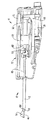
図1は、本発明によって製造された組織分離アセンブリーの、図示の明瞭化のためにそのハンドルの一部を省略して示す、部分概念全図である。
図1Aは、親ネジに取付けられた親ナットに形成されたスロット内でのピンの係合を示す、図1の1A−1A線に沿った略断面図である。
図2は、図1のアセンブリーの駆動部材の部分概念図である。
図3は、図1の3−3線に沿った、カテーテルアセンブリーの略断面図である。
図4は、図1のハウジング半部分を、駆動ネジ、駆動ナット、及び駆動ナットに接続されてそれと共に移動可能なL形状アクチュエーター、と共に示す斜視図である。
図5及び6は、前記アクチュエーターを図1の位置から移動させ、アクチュエーター延出部が分離ワイヤ押しネジを遠位方向に押して、この分離ワイヤを径方向外方に移動させた後の状態の、図1のハンドル及びカテーテルアセンブリーを図示している。
図7は、前記押しネジの偏垂直配置を示している、前記押しネジがブロックの前記スロットから出た直後の、前記ブロックと押しネジの概略端面図である。
図8は、前記ハウジングの外部から見える前記親ネジの近端部と、図10の分離ワイヤの位置に対応するその上に標識つけされた回転位置指示計、とを示している。
図9及び10は、前記駆動ネジが前記アクチュエーターを遠位側に移動させて、親ナットは、親ネジ、カテーテル軸及びそれとともに分離ワイヤを、約540°回転させて分離組織切片を作製した後の状態に於ける図5及び図6の構造を図示している。
図11及び12は、組織部保持部材の手動操作を図示している、
図13は、図12の構成部分の部分略図である。
図14は、図13の14−14線に沿ったカテーテルの断面図である。
図15及び16は、分離組織切片を包囲するための筒状編組部材の手動操作を図示している。
図17は、図16の構成部分の部分略図である。
【0014】
具体的実施例の説明
図1及び図2は、周囲組織、典型的には、患者の胸部内の組織、から標的組織を分離するために使用される組織分離アセンブリー10を図示している。標的組織の除去は、診断又は治療目的のものとすることができる。前記アセンブリー10は、ハンドル14から延出するカテーテルアセンブリー12を有する。通常は皮膚を貫く、カテーテルアセンブリー12の患者体内への導入は、好ましくは、たとえば、組織を貫く適当な通路を提供するための、外套針又はRFチップ、を使用することによって補助される。駆動ケーブル18と、ハンドルハウジング22に取付けられた駆動ケーブルコネクタ20とによって、ハンドル14にステップモーター16が接続されている。尚、これらの図面においては、ハンドルハウジング22の半部分のみが図示され、そのハウジングの他半部分は、それに実質的に類似したものである。駆動ケーブル18伝いにRF源24から、カテーテルアセンブリー12とハンドル14の内部とにRFエネルギが供給される。コントローラー26は、前記ステップモーター16と、更に、RF源24、の作動、たとえば、その作動速度やエネルギーレベル、を制御する。コントローラー26は、更に、ハンドル14とカテーテルアセンブリー12から、組織温度、抵抗力信号、回転方向、等の、適当なフィードバック信号を受信する。
【0015】
前記駆動ケーブル18は、駆動ネジ支持部材30,32によって、ハンドル14内の固定軸心方向位置に回転可能に取付けられた駆動ネジ28に接続されるとともに、このネジを回転させる。駆動ネジ28には駆動ナット34が螺合している。駆動ナット34にはL形状のアクチュエーター36が固定されている。このアクチュエーター36、図4を参照、は、ほぼ水平な土台部38と、ハンドル14内において、前記駆動ネジ28の軸心に対して平行に、移動するように寸法及び形状構成されたほぼ垂直な直立部40とを有する。従って、ステップモーター16によって駆動ネジ28を回転させると、アクチュエーター36は、ハウジング22内において、図1の初期位置から図10の位置へと摺動する。逆および往復移動も可能である。
【0016】
カテーテルアセンブリー12は、ハウジング22に取付けられるとともに該ハウジングから延出する導入シース42を備えている。カテーテルアセンブリー12は、更に、シース42を貫通し、図14−17を参照して後述する、アクチュエーターチューブ43と、このチューブ43を貫く軸44とを有する。図3を参照。前記軸44は、シース42の遠端部48から遠位側に延出する遠位部46と、ハンドル14の内部へと延出する近位部50とを有する。近位部50は、親ネジ52に固定されて、このネジと共に回転する。従って、軸44は親ネジ52と共に回転する。親ネジ52は、ハウジング22内において、このハウジング22内で回転は可能であるが、軸心方向には移動不能な状態で取付けられている。組織分離装置54が軸44に沿って延出し、これは、軸44の遠端部58に固定された分離ワイヤ部56を有する。この分離ワイヤ56は、遠位部46の外部に配置されている。組織分離装置54の大部分はワイヤとして構成され、軸44に形成された軸心方向穿孔60を通って延出している。前記分離装置54は、その近端部に径方向に延出する押しネジ62を有する。前記軸44の近端部は、軸心方向に延出するスロット64を備え、図2を参照、このスロットを通って、押しネジ62が延出している。従って、押しネジ62を遠位側、すなわち、図中において左側、に押すと、組織分離ワイヤ56は、その図1の縮径状態から外方に、図5及び6の拡径状態へと移動する。この外径方向移動は、一般的には、患者体内の標的部位、典型的には患者の胸部内、において行われる。組織を通る分離ワイヤの移動を補助するために、ワイヤ56には、RF源24からRFエネルギが供給される。機械的な往復又は機械的振動などの他のエネルギの利用も可能である。
【0017】
押しネジ62の軸心方向移動は、アクチュエーター36の軸心方向移動によって行われる。アクチュエーター36は、直立部40から遠位側に延出する延出部66を有する。この延出部66は、押しネジ62と位置合わせされた下方形成遠端部68を有する。ステップモーター16による駆動ネジ28の回転によって起こされるアクチュエーター40の初期の軸心方向移動によって、遠端部68と押しネジ62との間の小さな空隙70(図2を参照)が塞がれる。この小空隙によって、分離ワイヤ56の前記外径方向移動の前に、電気外科アークを開始することが可能とされる。アクチュエーター36を更に遠位側に移動させると、押しネジ62が遠位側に移動し、これによって、分離ワイヤ56を、図5及び6の位置へと外方に湾曲させる。図5及び6(但し図1ではない)は、親ネジ52の遠端部と、軸44の近端部とを支持するための、ハウジング22の一部である、支持ブロック72の使用を図示している。この支持ブロック72は、軸心方向に延出するスロット74を有し、図5及び7を参照、これは、最初、押しネジ62を収納する。支持ワイヤ56が完全に伸展された時、押しネジ62がスロット74から出て、面取り面を有する、前記延出部66の遠端部68によって、押しネジ62が、軸44と共に、図7の前記偏垂直位置へと回転し始める。同時にアクチュエーター36の直立部40が空隙73を閉じ(図2を参照)、親ネジ52に取り外し可能に取付けられた親ナット75に接触する。アクチュエーター36の直立部40からは回り止めピン76が延出し、これは、親ナット74に形成されたU形状スロット78内に収納されて、図1Aを参照、親ナット74がアクチュエーター36によって軸心方向に移動される時に、この親ナット74が親ネジ52周りを回転することを防止する。その代わりに、アクチュエーター36の軸心方向移動によって、親ネジ52が回転し、これによって、軸44を回転させる。アセンブリー10は、分離ワイヤ56の組織の貫通によって、組織切片80が周囲組織から完全に分離されるように軸44が約540°回転するように構成されている。分離ワイヤ56の径方向位置は、ハウジング22を通って露出された親ワイヤ52の近端部82を見ることによって容易に確認できる。図8を参照。近端部82は、分離ワイヤ56の回転位置に対応して、この近端部に形成された回転位置指示計84を有する。
【0018】
上述した一連の事象は、この開示された実施例に拠れば、一旦ユーザによって開始されれば、自動的に進行する。もちろん、分離ワイヤ56の進展、軸44の回転、ワイヤ56へのエネルギ供給、の内の単数又は複数の作動を含めた、装置の作動を、たとえば、軸44の回転に対する突然の抵抗、等に基づいて、手動で、又は、自動的に、終了させることも可能である。ここに開示した実施例の場合、以下の事象は手動で進行するが、このアセンブリーを、これらのうちのいずれか又は全部が自動的に行われうるように構成することも可能である。
【0019】
アセンブリー10は、更に、ハウジング22内に形成されたスロットから横方向外方に延出する一対の押しタブ88を備えたT型押し装置86を有する。図11−13を参照。軸44がその回転を完了した後、ユーザはタブ88を遠位側で押し始める。これによって、装置86の延出部90が、フリッパカム92を揺動ピン94回りで回転させる。このフリッパカム92は、一対の組織切片保持部材96の近端部に接続されている。これら保持部材96は、図3に図示されているように、軸44に形成された軸心方向穿孔98を貫くワイヤとして構成されている。これら保持部材96の遠端部は、好ましくはニチノール等の形状記憶材から形成された予形成フックワイヤ100であり、これらは、軸44の遠位部46に形成された開口部を貫いて、分離組織切片80に係合して、この組織部80を軸44の遠位部46に固定するのを補助する。
【0020】
前記装置86は、アクチュエーターチューブ43の近端部に接続された遠端部102を有する。従って、この装置86を移動させると、チューブ43が導入シース42内において遠位側に移動する。この時点では、すなわち、フックワイヤ100が図11−13のように展開された状態では、アクチュエーターチューブ43の遠端部に固定された筒状編組部材104、図14−17を参照、は、まだ完全にシース42内に収納されている。装置86を更に遠位側に移動させると、筒状編組部材104が、図15−17の位置へと、シース42の遠端部48を超えて外側に延出する。筒状編組部材104の目的は、分離組織切片と周囲の組織との間の切開面に沿って貫通することによって、この分離組織切片80を包囲することにある。部材104の開口外端部106は、この部材が組織を通して軸心方向に押される時に、自然に拡径する。部材104が適切な初期拡径を補助するために、軸44は、ガイド部材110に形成されるとともに、導入軸42の遠端部48の近傍に配置された、外向きに細くされたガイド面108を有する。ガイド部材110は、その近位側面に、図9の拡径状態にある時に分離ワイヤ56の近端部がその中を貫くスロットを有し、これは、分離ワイヤ56が回転中に折りたたまれることを防止するのに役立つ。所望の場合、前記筒状編組部材104の外端部106に、締め紐又はその他のタイプの閉鎖部材を設けることが可能である。いつ何時、筒状編組部材104内にほぼ収納され、フックワイヤ100によって軸44の遠位部46に固定された、分離組織切片80を、患者から除去することができる。
【0021】
本発明に拠れば、分離組織切片80は、患者から除去された時、その物質的完全性を、全部ではないにしても大部分保持している。又、前記筒状編組部材104を使用することは、特に、それが物質の通過に対してシール又はその他の方法で不透過性である場合、分離組織切片80の除去中に、疾患組織が組織管に沿って播種(seeding)される虞を減少させるのに役立つ。
【0022】
下記の請求項に定義された本発明の課題から逸脱することなく、ここに開示した実施例に対して改造及び変形を行うことが可能である。たとえば、米国特許第6,179,860号に開示されているもののような標的組織限局化装置を、アセンブリー10に組み込むことができ、そのような限局化装置は、図1において破線112によって示されているように展開され、図14の限局化装置アクチュエーター軸114は、軸44の遠位部46を標的部位に配置した後、アセンブリーを安定化させるのに役立ち、更に、筒状編組部材104との共同で、分離組織切片80を閉込めるのに役立つであろう。親ネジ52を中空構造にして、アクチュエーター軸114、又はその他の医療装置が、軸44内のルーメン内へとそれを貫くことを可能にすることができる。前記ステップモーター16、駆動ネジ28及び駆動ナット34に代えて、適当に構成された回避機構および/又は移動制動装置を備えたバネ駆動式ドライバー、等の他の駆動機構を使用することも可能である。前記好適実施例において、分離ワイヤ56がその完全な拡径状態に到達するまでは、軸44は回転し始めなかった。いくつかの状況においては、分離ワイヤ56の外方移動の前および/又は間、に軸44を回転開始させることが望ましいかもしれない。
【0023】
上述したすべての特許、特許出願及び刊行物をここに参考文献として合体させる。
【図面の簡単な説明】
【図1】本発明によって製造された組織分離アセンブリーの、図示の明瞭化のためにそのハンドルの一部を省略して示す、部分概念全図。
【図1A】親ネジに取付けられた親ナットに形成されたスロット内でのピンの係合を示す、図1の1A−1A線に沿った略断面図。
【図2】図1のアセンブリーの駆動部材の部分概念図。
【図3】図3は、図1の3−3線に沿った、カテーテルアセンブリーの略断面図。
【図4】図1のハウジング半部分を、駆動ネジ、駆動ナット、及び駆動ナットに接続されてそれと共に移動可能なL形状アクチュエーター、と共に示す斜視図。
【図5】アクチュエーターを図1の位置から移動させ、アクチュエーター延出部が分離ワイヤ押しネジを遠位方向に押して、この分離ワイヤを径方向外方に移動させた後の状態の、図1のハンドル及びカテーテルアセンブリーを図示している図。
【図6】アクチュエーターを図1の位置から移動させ、アクチュエーター延出部が分離ワイヤ押しネジを遠位方向に押して、この分離ワイヤを径方向外方に移動させた後の状態の、図1のハンドル及びカテーテルアセンブリーを図示している図。
【図7】前記押しネジの偏垂直配置を示している、前記押しネジがブロックの前記スロットから出た直後の、前記ブロックと押しネジの概略端面図。
【図8】前記ハウジングの外部から見える前記親ネジの近端部と、図10の分離ワイヤの位置に対応するその上に標識つけされた回転位置指示計、とを示している。
【図9】前記駆動ネジが前記アクチュエーターを遠位側に移動させて、親ナットは、親ネジ、カテーテル軸及びそれとともに分離ワイヤを、約540°回転させて分離組織切片を作製した後の状態に於ける図5及び図6の構造を図示している図。
【図10】前記駆動ネジが前記アクチュエーターを遠位側に移動させて、親ナットは、親ネジ、カテーテル軸及びそれとともに分離ワイヤを、約540°回転させて分離組織切片を作製した後の状態に於ける図5及び図6の構造を図示している図。
【図11】組織部保持部材の手動操作を図示している図。
【図12】組織部保持部材の手動操作を図示している図。
【図13】図12の構成部分の部分略図。
【図14】図13の14−14線に沿ったカテーテルの断面図。
【図15】分離組織切片を包囲するための筒状編組部材の手動操作を図示している図。
【図16】分離組織切片を包囲するための筒状編組部材の手動操作を図示している図。
【図17】図16の構成部分の部分略図。[0001]
Cross-reference of other applications
This application claims the benefit of US Provisional Patent Application No. 60 / 246,413, filed Nov. 7, 2000, entitled “Tissue Therapy and / or Removal Device and Use thereof”. Also, (1) US Pat. No. 6,179,860, issued on January 30, 2001, “Target tissue localization device and method” (2) International Publication No. WO 00/10471, published on March 2, 2000, “Target Tissue Localization Device and Method”, (3) US Pat. No. 6,221,006, issued on Apr. 24, 2001, “Capture Device and its Use”, (4) International Publication No. WO99 / 39648, Published August 12, 1999, “Capture Device and Method of Use”, (5) US Patent Application No. 09 / 588,278, filed June 5, 2000, “Tissue Removal Method and Device”, and ( 6) See also International Publication WO 00/74561, published December 14, 2000, “Tissue Removal Method and Apparatus”.
[0002]
Background of the Invention
MD Anderson Cancer Center in Houston, Texas, predicts that by 2002, cancer will be the first cause of death in the United States. Currently, cancer kills more than 1,500 lives every day in the United States (550,000 deaths annually). There are many treatments for cancer, and the research is continuing eagerly. Nevertheless, the still preferred treatment is physical removal of the cancer. When available, surgical removal is preferred (chest, colon, brain, lung, kidney, etc.). Incisions, excisions, and surgical removal are often very invasive, and efforts to remove cancer tissue in a less invasive manner continue, but have not yet been completed.
[0003]
The only cure for cancer is still early diagnosis and subsequent early treatment. As cancer treatment is increasingly performed at an early stage of diagnosis, the cancer tissue that is operated on is becoming smaller and smaller. In order to remove small cancers initially, new techniques are needed for the removal and removal of these less invasive cancers.
[0004]
There are various techniques that attempt to achieve minimally invasive cancer therapy, but so far the results have not been sufficiently improved. For example, the US Surgical ABBI system and the ImaGyn Site Select system attempt to achieve a less invasive cancer therapy. However, conventional techniques require more than minimally invasive surgery (MIS) techniques in that they require excision of large cores (with a diameter of about 15 mm or more). In addition, Johnson and Johnson's Mammotome system and US Surgical's MIBB system also require a large core (about 4 mm or more in diameter) to achieve a biopsy.
[0005]
In a recent meeting held on March 13, 2000 by the American Society of Surgical Oncologists, the traditional stereotactic core biopsy (SCB), especially non-invasive breast ducts In the case of cancer (DCIS), it was reported to be insufficient to provide a definitive response to this fine precision surgical regimen after this SCB-type aspiration biopsy. Of course, in such a percutaneous system, “normal” tissue cells are damaged, and those cells are “normally damaged” cells, or early precancerous lesions (eg, atypical milk). It is difficult to determine whether it is a tube hyperplasia (ADH) cell).
[0006]
Studies presented by Dr. Ollila et al. At the University of North Carolina, Chapel Hill, have shown that histology and pathological damage can occur using these conventional techniques because of the damage done to the removed tissue specimen. I showed you to do. Improvements to conventional aspiration needle biopsy systems have become increasingly strong for a number of reasons, including the fact that DCIS has become increasingly detectable and has become increasingly common in the diagnosis of breast cancer in the United States. It has been demanded.
[0007]
Summary of the Invention
One aspect of the present invention relates to a tissue separation assembly having a proximal end assembly, typically a handle, and a catheter assembly extending from the proximal end assembly. The catheter assembly includes a shaft and a longitudinal tissue separating member whose distal portion is movable between a retracted state and an outwardly extending operation state. The proximal end assembly is connected to the tissue separating member, (1) moves the tissue separating member from the retracted state to the operating state, and (2) moves the tissue separating member around an axis. And a first driver configured to automatically rotate the tissue section so that the tissue section can be separated from the surrounding tissue by moving the tissue separating member.
[0008]
Another aspect of the invention relates to a tissue separation assembly having the proximal end assembly, usually a handle, and a catheter assembly extending from the proximal end assembly. The catheter assembly includes a shaft and a longitudinal tissue separating member whose distal portion is movable between a retracted state, an outward curve, and an operating state. An energy source is selectively connected to the tissue separation member. The proximal end assembly is connected to the tissue separating member, (1) moves the tissue separating member from the retracted state to the operating state, and (2) moves the tissue separating member around an axis. And a first driver configured to automatically rotate the tissue separating member so that the tissue section can be separated from the surrounding tissue by moving the tissue separating member. The catheter assembly is further provided at a distal portion of the shaft and is movable from a retracted position to an expanded, tissue engaged state to assist in securing an isolated tissue section to the catheter assembly. A tissue holding member. The catheter assembly further includes a tubular braided member which is provided at a distal portion of the shaft and surrounds the tissue separating member and the separated tissue section and is movable to an expanded diameter state. The near end assembly further includes a second driver connected to the holding member and the tubular braided member. The second driver is configured to move the holding member to the expanded tissue engaged state and to move the cylindrical braided member to the far end side diameter expanded state.
[0009]
Another aspect of the invention relates to a tissue separation assembly having a proximal end assembly, usually a handle, and a catheter assembly extending from the proximal end assembly. The catheter assembly has a shaft and a movable tissue separating member. The proximal end assembly has a first driver connected to the tissue separating member and configured to drive the tissue separating member through the tissue to separate the tissue section from the surrounding tissue. The catheter assembly is further provided at the distal portion of the shaft and is movable from a retracted state to an expanded, tissue-engaged state to assist in securing an isolated tissue section to the catheter assembly. It has a holding member. The catheter assembly further includes a tubular braided member that is provided at the distal portion of the shaft and surrounds the tissue separating member and the separated tissue section and is movable to an expanded diameter state. The near end assembly further includes a second driver connected to the holding member and the tubular braided member. The second driver is configured to move the holding member to the expanded tissue engaged state and to move the tubular braided member to the distal diameter-expanded state.
[0010]
Yet another aspect of the invention relates to a method for making a tissue section in the surrounding tissue. The method includes positioning the distal end of the catheter assembly at a target location within the patient. A longitudinal tissue separation member provided at the distal end of the catheter assembly is moved to an outward extending operation state. The separation member is automatically rotated around the axis after at least the start of the separation member moving step for separating the tissue section from the surrounding tissue. The method further includes moving a tissue retention member disposed at the distal end of the catheter assembly from a retracted state to an expanded tissue engaged state. Further, the method can include the step of surrounding the separated tissue section with a tubular braided member.
[0011]
Yet another aspect of the present invention relates to a method for forming a tissue section in the surrounding tissue. The method includes positioning the distal end of the catheter assembly at a target location within the patient's chest. A longitudinal tissue separating member provided at the distal end portion of the catheter assembly is moved to a diameter-enlarged and outwardly curved operation state. Energy is supplied to the separation member. The separation member is automatically rotated about an axis after at least the start of the separation member moving step for separating a tissue section from surrounding tissue. The tissue holding member disposed at the distal end of the catheter assembly is moved from the retracted state to the expanded tissue engaged state. Further, after the automatic rotation step, the separated tissue section moves the tubular braided member provided at the distal end portion of the catheter assembly from the proximal reduced diameter state to the distal enlarged diameter state. By doing so, it is surrounded by this tubular braided member.
[0012]
Other features and advantages of the present invention will become apparent from the following description in which the preferred embodiments are set forth in detail with reference to the accompanying drawings.
[0013]
Brief Description of Drawings
FIG. 1 is a partial conceptual full view of a tissue separation assembly manufactured according to the present invention, with a portion of its handle omitted for clarity of illustration.
FIG. 1A is a schematic cross-sectional view taken along line 1A-1A of FIG. 1, showing the engagement of pins in a slot formed in a parent nut attached to a lead screw.
FIG. 2 is a partial conceptual view of a drive member of the assembly of FIG.
FIG. 3 is a schematic cross-sectional view of the catheter assembly taken along line 3-3 of FIG.
FIG. 4 is a perspective view showing the housing half of FIG. 1 with a drive screw, a drive nut, and an L-shaped actuator connected to the drive nut and movable therewith.
FIGS. 5 and 6 show the state after the actuator is moved from the position of FIG. 1 and the actuator extension pushes the separation wire push screw in the distal direction to move the separation wire radially outward. Figure 2 illustrates the handle and catheter assembly of Figure 1;
FIG. 7 is a schematic end view of the block and the push screw immediately after the push screw has exited the slot of the block, showing a partial vertical arrangement of the push screw.
FIG. 8 shows the proximal end of the lead screw visible from the outside of the housing and a rotational position indicator labeled thereon corresponding to the position of the separation wire of FIG.
FIGS. 9 and 10 show that after the drive screw has moved the actuator distally and the parent nut has rotated the lead wire, the catheter shaft and the separation wire with it about 540 ° to create a separate tissue section. The structure of FIG.5 and FIG.6 in the state of this is shown in figure.
11 and 12 illustrate the manual operation of the tissue holding member,
13 is a partial schematic diagram of the components of FIG.
14 is a cross-sectional view of the catheter taken along line 14-14 of FIG.
15 and 16 illustrate the manual operation of the tubular braided member to surround the isolated tissue section.
FIG. 17 is a partial schematic view of the components of FIG.
[0014]
Description of specific examples
1 and 2 illustrate a
[0015]
The
[0016]
[0017]
The axial movement of the
[0018]
The series of events described above proceeds automatically according to the disclosed embodiment once initiated by the user. Of course, the operation of the device, including the movement of the
[0019]
The
[0020]
The
[0021]
In accordance with the present invention, the
[0022]
Modifications and variations can be made to the embodiments disclosed herein without departing from the scope of the present invention as defined in the following claims. For example, a target tissue localization device, such as that disclosed in US Pat. No. 6,179,860, can be incorporated into
[0023]
All patents, patent applications and publications mentioned above are hereby incorporated by reference.
[Brief description of the drawings]
FIG. 1 is a partial conceptual full view of a tissue separation assembly manufactured in accordance with the present invention, with a portion of its handle omitted for clarity of illustration.
1A is a schematic cross-sectional view taken along line 1A-1A of FIG. 1, showing the engagement of a pin in a slot formed in a parent nut attached to a lead screw.
FIG. 2 is a partial conceptual diagram of a drive member of the assembly of FIG.
FIG. 3 is a schematic cross-sectional view of the catheter assembly taken along line 3-3 of FIG.
4 is a perspective view showing the housing half of FIG. 1 with a drive screw, a drive nut, and an L-shaped actuator connected to and movable with the drive nut. FIG.
5 shows the state of FIG. 1 after the actuator has been moved from the position of FIG. 1 and the actuator extension has pushed the separation wire push screw distally to move the separation wire radially outward. FIG. 4 illustrates a handle and catheter assembly.
6 shows the state of FIG. 1 after the actuator has been moved from the position of FIG. 1 and the actuator extension has pushed the separation wire push screw distally to move the separation wire radially outward. FIG. 4 illustrates a handle and catheter assembly.
FIG. 7 is a schematic end view of the block and the push screw immediately after the push screw exits the slot of the block, showing a partial vertical arrangement of the push screw.
8 shows the proximal end of the lead screw visible from the exterior of the housing and a rotational position indicator labeled thereon corresponding to the position of the separation wire of FIG.
FIG. 9 shows the state after the drive screw moves the actuator to the distal side and the parent nut rotates the lead screw, the catheter shaft and the separation wire together with the separation screw by about 540 ° to produce a separated tissue section. The figure which shows the structure of FIG.5 and FIG.6 in FIG.
FIG. 10 shows the state after the drive screw moves the actuator to the distal side and the parent nut rotates the lead screw, the catheter shaft and the separation wire together with the separation screw by about 540 ° to produce a separated tissue section. The figure which shows the structure of FIG.5 and FIG.6 in FIG.
FIG. 11 is a diagram illustrating manual operation of a tissue holding member.
FIG. 12 is a diagram illustrating manual operation of a tissue holding member.
13 is a partial schematic diagram of the components of FIG.
14 is a cross-sectional view of the catheter taken along line 14-14 of FIG.
FIG. 15 is a diagram illustrating manual operation of a tubular braided member for surrounding a separated tissue section.
FIG. 16 is a diagram illustrating manual operation of a tubular braided member for surrounding a separated tissue section.
FIG. 17 is a partial schematic view of the components shown in FIG.
Claims (44)
近端部アセンブリー、
前記近端部アセンブリーから延出するカテーテルアセンブリー、これは以下を有する、
遠位部を有し、この遠位部に軸心を定める軸、
近位部と遠位部とを有する長手組織分離部材、前記遠位部は前記軸の前記遠位部に接続され、かつ、前記遠位部の近傍で退縮状態と、外方延出操作状態との間を移動可能である、そして
前記軸の前記遠位部に設けられて、近位側縮径状態と遠位側拡径状態との間で、長手方向かつ径方向に移動可能な、ほぼ筒状もしくは円錐状の編組部材、そして
前記近端部アセンブリーは、前記組織分離部材に作動接続され、かつ、(1)前記組織分離部材を前記退縮状態から前記操作状態へと移動させ、(2)前記組織分離部材を軸心周りで自動的に回転させ、それによって、前記組織分離部材を動かすことによって組織切片をその周囲の組織から分離可能とし、このほぼ筒状もしくは円錐状の編組部材は、前記遠位側拡径状態時に、前記組織分離部材と分離組織切片とを包囲する、
ように構成された第1ドライバーを有する、
ことを特徴とする、組織分離アセンブリー。A tissue separation assembly comprising:
Near end assembly,
A catheter assembly extending from the proximal end assembly, comprising:
An axis having a distal portion and defining an axis in the distal portion;
A longitudinal tissue separating member having a proximal portion and a distal portion, wherein the distal portion is connected to the distal portion of the shaft, and is in a retracted state and an outward extending operation state in the vicinity of the distal portion And can be moved longitudinally and radially between a proximal reduced diameter state and a distal enlarged diameter state provided at the distal portion of the shaft. A substantially cylindrical or conical braided member, and the proximal end assembly operatively connected to the tissue separating member, and (1) moving the tissue separating member from the retracted state to the operating state, 2) The tissue separating member is automatically rotated around an axis, whereby the tissue section can be separated from the surrounding tissue by moving the tissue separating member, and the substantially cylindrical or conical braided member. Is the tissue separating member when the diameter of the distal side is expanded Surrounding a separation tissue sections,
A first driver configured to
A tissue separation assembly characterized in that
前記保持部材を前記退縮状態から前記拡張、組織係合状態へと移動させ、かつ、
前記ほぼ筒状もしくは円錐状の編組部材を前記近位側縮径状態から前記遠位側拡径状態へと移動させる、ように構成された第2ドライバーを有する、
ことを特徴とする、請求項1のアセンブリー。The proximal end assembly is operatively connected to the holding member and a generally cylindrical or conical braided member;
Moving the retaining member from the retracted state to the expanded, tissue engaged state; and
A second driver configured to move the substantially cylindrical or conical braided member from the proximal reduced diameter state to the distal enlarged diameter state;
The assembly of claim 1, wherein:
近端部アセンブリー、
前記近端部アセンブリーから延出するカテーテルアセンブリー、これは以下を有する、
遠位部を有するとともに、この遠位部に軸心を定める軸、そして
近位部と遠位部とを有する長手組織分離部材、前記遠位部は前記軸の前記遠位部に接続され、前記遠位部の近傍で退縮状態と、外側に湾曲した操作状態との間を移動可能である、
前記組織分離部材に選択的に接続されるエネルギ源、
前記近端部アセンブリーは、前記組織分離部材に作動接続されるとともに、(1)前記組織分離部材を前記退縮状態から前記作動状態へと移動させ、かつ、その後に、(2)前記組織分離部材を前記軸心回りで自動的に回転させ、これによって、前記組織分離部材を移動させることによって、組織切片を周囲組織から分離可能とする、ように構成された第1ドライバーを有する、
前記カテーテルアセンブリーは以下を有する、
前記軸の前記遠位部に設けられた組織切片保持部材、前記保持部材は、分離組織切片の前記カテーテルアセンブリーに対する固定を補助する、退縮状態から拡張、組織係合状態へ移動可能である、
前記軸の前記遠位部に設けられ、近位側縮径状態と遠位側拡径状態との間で、長手方向及び径方向に移動可能なほぼ筒状もしくは円錐状の編組部材、該ほぼ筒状もしくは円錐状の編組部材は、前記遠位側拡径状態時に、前記組織分離部材と分離組織切片とを包囲する、そして
前記近端部アセンブリーは、前記保持部材と前記ほぼ筒状もしくは円錐状の編組部材とに作動接続され、
前記保持部材を前記退縮状態から前記拡張組織係合状態へと移動させ、かつ、
前記ほぼ筒状もしくは円錐状の編組部材を前記近位側縮径状態から前記遠位側拡径状態へと移動させる、ように構成される第2ドライバーを有する、
ことを特徴とする、組織分離アセンブリー。A tissue separation assembly comprising:
Near end assembly,
A catheter assembly extending from the proximal end assembly, comprising:
A longitudinal tissue separating member having a distal portion and defining an axis in the distal portion, and a proximal portion and a distal portion, the distal portion being connected to the distal portion of the shaft; It is movable between a retracted state in the vicinity of the distal portion and an operating state curved outward.
An energy source selectively connected to the tissue separating member;
The proximal end assembly is operatively connected to the tissue separation member and (1) moves the tissue separation member from the retracted state to the activated state and then (2) the tissue separation member Having a first screwdriver configured to automatically rotate about the axis and thereby move the tissue separating member to allow the tissue section to be separated from the surrounding tissue;
The catheter assembly comprises:
A tissue section retaining member provided at the distal portion of the shaft, the retaining member is movable from a retracted state to an expanded, tissue engaged state that assists in securing a separate tissue section to the catheter assembly;
A substantially cylindrical or conical braided member provided at the distal portion of the shaft and movable longitudinally and radially between a proximal diameter-reduced state and a distal diameter-enlarged state; A tubular or conical braided member surrounds the tissue separating member and the separated tissue section in the distal diameter expanded state, and the proximal end assembly comprises the holding member and the substantially tubular or conical shape. Operatively connected to the shaped braided member,
Moving the retaining member from the retracted state to the expanded tissue engaged state; and
Wherein having a substantially cylindrical or the conical braided member is moved to the distal enlarged state from the proximal side radially reduced diameter state, second drivers adapted,
A tissue separation assembly characterized in that
前記第1ドライバーは、前記軸に回転可能に接続された親ネジを有し、これによって、前記親ネジの回転によって前記軸が回転する、
ことを特徴とする、請求項23のアセンブリー。The first driver has an actuator that is movable along a path from a first position to a second position and a third position, wherein the actuator moves the distal portion of the tissue separating member. A first portion engageable with the proximal portion of the tissue separating member when moving between the first and second positions to move from the retracted state to the operating state;
The first driver has a lead screw rotatably connected to the shaft, whereby the shaft is rotated by the rotation of the lead screw.
24. The assembly of claim 23, wherein:
近端部アセンブリー、
前記近端部アセンブリーから延出するカテーテルアセンブリー、これは以下を有する、
遠位部を有するとともにこの遠位部に軸心を定める軸、そして
前記軸の前記遠位部に設けられ、組織を貫きそれを分離するために、退縮状態と拡張、操作状態との間を移動可能な組織分離手段、
前記軸の前記遠位部に設けられて、近位側縮径状態と遠位側拡径状態との間で、長手方向かつ径方向に移動可能な、ほぼ筒状もしくは円錐状の編組部材、そして
前記近端部アセンブリーは、(1)前記組織分離手段を前記退縮状態から前記拡張操作状態へと移動させ、かつ(2)前記組織分離部材を前記軸心回りで自動的に回転させ、それによって、組織切片を周囲組織から分離可能とする、ための手段を有し、このほぼ筒状もしくは円錐状の編組部材は、前記遠位側拡径状態時に、前記組織分離部材と分離組織切片とを包囲する、
ことを特徴とする、組織分離アセンブリー。A tissue separation assembly comprising:
Near end assembly,
A catheter assembly extending from the proximal end assembly, comprising:
A shaft having a distal portion and defining an axis in the distal portion; and provided at the distal portion of the shaft, between a retracted state and an expanded, manipulated state for penetrating tissue and separating it. Movable tissue separation means,
A substantially tubular or conical braided member provided at the distal portion of the shaft and movable longitudinally and radially between a proximal reduced diameter state and a distal expanded diameter state; And the proximal end assembly (1) moves the tissue separating means from the retracted state to the expanded operation state, and (2) automatically rotates the tissue separating member about the axis, Means for separating the tissue section from the surrounding tissue, and the substantially cylindrical or conical braided member includes the tissue separating member and the separated tissue section in the distal-side expanded state. Siege,
A tissue separation assembly characterized in that
近端部アセンブリー、
前記近端部アセンブリーから延出するカテーテルアセンブリー、これは以下を有する、
遠位部を有するとともにこの遠位部に軸心を定める軸、そして
前記軸の前記遠位部に設けられた移動可能組織分離部材、
前記近端部アセンブリーは、前記組織分離部材に作動接続されるとともに、前記組織分離部材を組織を通して駆動して組織切片を周囲組織から分離するように構成された第1ドライバーを有する、
前記カテーテルアセンブリーは以下を有する、
前記軸の前記遠位部に設けられた組織切片保持部材、該保持部材は、分離組織切片の前記カテーテルアセンブリーに対する固定を補助するべく、退縮状態から拡張、組織係合状態へと移動可能である、
前記軸の前記遠位部に設けられ、近位側縮径状態と遠位側拡径状態との間で、長手方向及び径方向に移動可能なほぼ筒状もしくは円錐状の編組部材、該ほぼ筒状もしくは円錐状の編組部材は、前記遠位側拡径状態時に、前記組織分離部材と、分離組織切片とを包囲する、そして
前記近端部アセンブリーは、前記保持部材と前記ほぼ筒状もしくは円錐状の編組部材とに作動接続されるとともに、
前記保持部材を前記退縮状態から前記拡張、組織係合状態へと移動させ、かつ
前記ほぼ筒状もしくは円錐状の編組部材を前記近位側縮径状態から前記遠位側拡径状態へと移動させる、ように構成される第2ドライバーを有する、
ことを特徴とする、組織分離アセンブリー。A tissue separation assembly comprising:
Near end assembly,
A catheter assembly extending from the proximal end assembly, comprising:
A shaft having a distal portion and defining an axis in the distal portion; and a movable tissue separating member provided at the distal portion of the shaft;
The proximal end assembly has a first driver operatively connected to the tissue separation member and configured to drive the tissue separation member through tissue to separate a tissue section from surrounding tissue.
The catheter assembly comprises:
A tissue section holding member provided at the distal portion of the shaft, the holding member being movable from a retracted state to an expanded, tissue engaged state to assist in securing the isolated tissue section to the catheter assembly; is there,
A substantially cylindrical or conical braided member provided at the distal portion of the shaft and movable longitudinally and radially between a proximal diameter-reduced state and a distal diameter-enlarged state; A tubular or conical braided member surrounds the tissue separating member and the separated tissue section in the distal diameter-enlarged state, and the proximal end assembly comprises the holding member and the substantially tubular or Operatively connected to the conical braided member,
The holding member is moved from the retracted state to the expanded and tissue engaged state, and the substantially cylindrical or conical braided member is moved from the proximal reduced diameter state to the distal enlarged diameter state. Having a second driver configured to,
A tissue separation assembly characterized in that
近端部アセンブリー、
組織を貫きそれを分離するための組織分離手段を有する、前記近端部アセンブリーから延出するカテーテルアセンブリー、
前記近端部アセンブリーは、前記組織分離手段を組織を通して駆動して組織切片を周囲組織から分離するための第1駆動手段を有する、
前記カテーテルアセンブリーは、
分離組織切片の前記カテーテルアセンブリーに対する固定を補助するための組織穿孔手段、そして
前記組織分離手段と分離組織切片とを包囲するための手段、を有し、そして
前記近端部アセンブリーは、
前記組織穿孔手段を分離組織切片内へと駆動するとともに、
前記包囲手段を駆動する、ための第2駆動手段を有する、
ことを特徴とする、組織分離アセンブリー。A tissue separation assembly comprising:
Near end assembly,
A catheter assembly extending from the proximal end assembly having tissue separating means for penetrating and separating the tissue;
The proximal end assembly has first drive means for driving the tissue separating means through tissue to separate a tissue section from surrounding tissue;
The catheter assembly includes
A tissue piercing means for assisting in securing the separated tissue section to the catheter assembly, and a means for enclosing the tissue separating means and the separated tissue section, and the proximal end assembly comprises:
Driving the tissue piercing means into a separate tissue section;
Second driving means for driving the surrounding means;
A tissue separation assembly characterized in that
Applications Claiming Priority (2)
| Application Number | Priority Date | Filing Date | Title |
|---|---|---|---|
| US24641300P | 2000-11-07 | 2000-11-07 | |
| PCT/US2001/050978 WO2002076281A2 (en) | 2000-11-07 | 2001-11-07 | Tissue separator assembly and method |
Publications (3)
| Publication Number | Publication Date |
|---|---|
| JP2004529689A JP2004529689A (en) | 2004-09-30 |
| JP2004529689A5 JP2004529689A5 (en) | 2005-12-22 |
| JP4180382B2 true JP4180382B2 (en) | 2008-11-12 |
Family
ID=22930569
Family Applications (1)
| Application Number | Title | Priority Date | Filing Date |
|---|---|---|---|
| JP2002574803A Expired - Fee Related JP4180382B2 (en) | 2000-11-07 | 2001-11-07 | Tissue separation assembly and tissue separation method |
Country Status (4)
| Country | Link |
|---|---|
| US (2) | US20030083656A1 (en) |
| EP (1) | EP1341435A4 (en) |
| JP (1) | JP4180382B2 (en) |
| WO (2) | WO2002064012A2 (en) |
Families Citing this family (313)
| Publication number | Priority date | Publication date | Assignee | Title |
|---|---|---|---|---|
| US8795332B2 (en) | 2002-09-30 | 2014-08-05 | Ethicon, Inc. | Barbed sutures |
| US6006134A (en) | 1998-04-30 | 1999-12-21 | Medtronic, Inc. | Method and device for electronically controlling the beating of a heart using venous electrical stimulation of nerve fibers |
| US5931855A (en) | 1997-05-21 | 1999-08-03 | Frank Hoffman | Surgical methods using one-way suture |
| US6997885B2 (en) * | 1998-04-08 | 2006-02-14 | Senorx, Inc. | Dilation devices and methods for removing tissue specimens |
| US7618426B2 (en) | 2002-12-11 | 2009-11-17 | Usgi Medical, Inc. | Apparatus and methods for forming gastrointestinal tissue approximations |
| US8574243B2 (en) | 1999-06-25 | 2013-11-05 | Usgi Medical, Inc. | Apparatus and methods for forming and securing gastrointestinal tissue folds |
| US8016877B2 (en) | 1999-11-17 | 2011-09-13 | Medtronic Corevalve Llc | Prosthetic valve for transluminal delivery |
| US7018406B2 (en) | 1999-11-17 | 2006-03-28 | Corevalve Sa | Prosthetic valve for transluminal delivery |
| US8579966B2 (en) | 1999-11-17 | 2013-11-12 | Medtronic Corevalve Llc | Prosthetic valve for transluminal delivery |
| US7842068B2 (en) | 2000-12-07 | 2010-11-30 | Integrated Vascular Systems, Inc. | Apparatus and methods for providing tactile feedback while delivering a closure device |
| US6461364B1 (en) | 2000-01-05 | 2002-10-08 | Integrated Vascular Systems, Inc. | Vascular sheath with bioabsorbable puncture site closure apparatus and methods of use |
| US8758400B2 (en) | 2000-01-05 | 2014-06-24 | Integrated Vascular Systems, Inc. | Closure system and methods of use |
| US6391048B1 (en) | 2000-01-05 | 2002-05-21 | Integrated Vascular Systems, Inc. | Integrated vascular device with puncture site closure component and sealant and methods of use |
| US9579091B2 (en) | 2000-01-05 | 2017-02-28 | Integrated Vascular Systems, Inc. | Closure system and methods of use |
| US8241274B2 (en) | 2000-01-19 | 2012-08-14 | Medtronic, Inc. | Method for guiding a medical device |
| US7749245B2 (en) | 2000-01-27 | 2010-07-06 | Medtronic, Inc. | Cardiac valve procedure methods and devices |
| WO2001085030A1 (en) * | 2000-05-09 | 2001-11-15 | Paieon Inc. | System and method for three-dimensional reconstruction of an artery |
| US7534242B2 (en) * | 2003-02-25 | 2009-05-19 | Artemis Medical, Inc. | Tissue separating catheter assembly and method |
| US20030204188A1 (en) * | 2001-11-07 | 2003-10-30 | Artemis Medical, Inc. | Tissue separating and localizing catheter assembly |
| WO2002005888A1 (en) | 2000-06-30 | 2002-01-24 | Viacor Incorporated | Intravascular filter with debris entrapment mechanism |
| CA2419811A1 (en) | 2000-08-18 | 2002-02-28 | Atritech, Inc. | Expandable implant devices for filtering blood flow from atrial appendages |
| DE60144328D1 (en) | 2000-09-08 | 2011-05-12 | Abbott Vascular Inc | Surgical clamp |
| US6626918B1 (en) * | 2000-10-06 | 2003-09-30 | Medical Technology Group | Apparatus and methods for positioning a vascular sheath |
| US7211101B2 (en) | 2000-12-07 | 2007-05-01 | Abbott Vascular Devices | Methods for manufacturing a clip and clip |
| US8690910B2 (en) | 2000-12-07 | 2014-04-08 | Integrated Vascular Systems, Inc. | Closure device and methods for making and using them |
| US6623510B2 (en) | 2000-12-07 | 2003-09-23 | Integrated Vascular Systems, Inc. | Closure device and methods for making and using them |
| US7905900B2 (en) | 2003-01-30 | 2011-03-15 | Integrated Vascular Systems, Inc. | Clip applier and methods of use |
| IES20010547A2 (en) | 2001-06-07 | 2002-12-11 | Christy Cummins | Surgical Staple |
| US8623077B2 (en) | 2001-06-29 | 2014-01-07 | Medtronic, Inc. | Apparatus for replacing a cardiac valve |
| US7056331B2 (en) | 2001-06-29 | 2006-06-06 | Quill Medical, Inc. | Suture method |
| US8771302B2 (en) | 2001-06-29 | 2014-07-08 | Medtronic, Inc. | Method and apparatus for resecting and replacing an aortic valve |
| US7544206B2 (en) | 2001-06-29 | 2009-06-09 | Medtronic, Inc. | Method and apparatus for resecting and replacing an aortic valve |
| FR2826863B1 (en) | 2001-07-04 | 2003-09-26 | Jacques Seguin | ASSEMBLY FOR PLACING A PROSTHETIC VALVE IN A BODY CONDUIT |
| FR2828091B1 (en) | 2001-07-31 | 2003-11-21 | Seguin Jacques | ASSEMBLY ALLOWING THE PLACEMENT OF A PROTHETIC VALVE IN A BODY DUCT |
| US7097659B2 (en) | 2001-09-07 | 2006-08-29 | Medtronic, Inc. | Fixation band for affixing a prosthetic heart valve to tissue |
| US6749621B2 (en) | 2002-02-21 | 2004-06-15 | Integrated Vascular Systems, Inc. | Sheath apparatus and methods for delivering a closure device |
| US8721713B2 (en) * | 2002-04-23 | 2014-05-13 | Medtronic, Inc. | System for implanting a replacement valve |
| EP1513453B1 (en) | 2002-06-04 | 2008-12-17 | Abbott Vascular Inc | Blood vessel closure clip and delivery device |
| US6773450B2 (en) | 2002-08-09 | 2004-08-10 | Quill Medical, Inc. | Suture anchor and method |
| US8100940B2 (en) | 2002-09-30 | 2012-01-24 | Quill Medical, Inc. | Barb configurations for barbed sutures |
| US20040088003A1 (en) * | 2002-09-30 | 2004-05-06 | Leung Jeffrey C. | Barbed suture in combination with surgical needle |
| US8123698B2 (en) * | 2002-10-07 | 2012-02-28 | Suros Surgical Systems, Inc. | System and method for minimally invasive disease therapy |
| EP1567083A4 (en) * | 2002-11-13 | 2008-08-20 | Artemis Medical Inc | Devices and methods for controlling initial movement of an electrosurgical electrode |
| EP1567106B1 (en) | 2002-11-18 | 2009-12-23 | Bard Peripheral Vascular, Inc. | Apparatus for implanting a preloaded localization wire |
| US7942884B2 (en) | 2002-12-11 | 2011-05-17 | Usgi Medical, Inc. | Methods for reduction of a gastric lumen |
| US7942898B2 (en) | 2002-12-11 | 2011-05-17 | Usgi Medical, Inc. | Delivery systems and methods for gastric reduction |
| US8398656B2 (en) | 2003-01-30 | 2013-03-19 | Integrated Vascular Systems, Inc. | Clip applier and methods of use |
| US8758398B2 (en) | 2006-09-08 | 2014-06-24 | Integrated Vascular Systems, Inc. | Apparatus and method for delivering a closure element |
| US8905937B2 (en) | 2009-02-26 | 2014-12-09 | Integrated Vascular Systems, Inc. | Methods and apparatus for locating a surface of a body lumen |
| US8821534B2 (en) | 2010-12-06 | 2014-09-02 | Integrated Vascular Systems, Inc. | Clip applier having improved hemostasis and methods of use |
| US8202293B2 (en) | 2003-01-30 | 2012-06-19 | Integrated Vascular Systems, Inc. | Clip applier and methods of use |
| US8216252B2 (en) | 2004-05-07 | 2012-07-10 | Usgi Medical, Inc. | Tissue manipulation and securement system |
| US20120289859A9 (en) * | 2003-08-27 | 2012-11-15 | Nicoson Zachary R | System and method for minimally invasive disease therapy |
| US8172770B2 (en) * | 2005-09-28 | 2012-05-08 | Suros Surgical Systems, Inc. | System and method for minimally invasive disease therapy |
| US9579194B2 (en) | 2003-10-06 | 2017-02-28 | Medtronic ATS Medical, Inc. | Anchoring structure with concave landing zone |
| US7186265B2 (en) * | 2003-12-10 | 2007-03-06 | Medtronic, Inc. | Prosthetic cardiac valves and systems and methods for implanting thereof |
| US7361180B2 (en) | 2004-05-07 | 2008-04-22 | Usgi Medical, Inc. | Apparatus for manipulating and securing tissue |
| US7347863B2 (en) | 2004-05-07 | 2008-03-25 | Usgi Medical, Inc. | Apparatus and methods for manipulating and securing tissue |
| US7329279B2 (en) | 2003-12-23 | 2008-02-12 | Sadra Medical, Inc. | Methods and apparatus for endovascularly replacing a patient's heart valve |
| US8052749B2 (en) | 2003-12-23 | 2011-11-08 | Sadra Medical, Inc. | Methods and apparatus for endovascular heart valve replacement comprising tissue grasping elements |
| US20050137691A1 (en) * | 2003-12-23 | 2005-06-23 | Sadra Medical | Two piece heart valve and anchor |
| US20120041550A1 (en) | 2003-12-23 | 2012-02-16 | Sadra Medical, Inc. | Methods and Apparatus for Endovascular Heart Valve Replacement Comprising Tissue Grasping Elements |
| US8603160B2 (en) | 2003-12-23 | 2013-12-10 | Sadra Medical, Inc. | Method of using a retrievable heart valve anchor with a sheath |
| US7445631B2 (en) * | 2003-12-23 | 2008-11-04 | Sadra Medical, Inc. | Methods and apparatus for endovascularly replacing a patient's heart valve |
| US7988724B2 (en) | 2003-12-23 | 2011-08-02 | Sadra Medical, Inc. | Systems and methods for delivering a medical implant |
| US7748389B2 (en) * | 2003-12-23 | 2010-07-06 | Sadra Medical, Inc. | Leaflet engagement elements and methods for use thereof |
| US20050137694A1 (en) | 2003-12-23 | 2005-06-23 | Haug Ulrich R. | Methods and apparatus for endovascularly replacing a patient's heart valve |
| US20050137696A1 (en) * | 2003-12-23 | 2005-06-23 | Sadra Medical | Apparatus and methods for protecting against embolization during endovascular heart valve replacement |
| US8343213B2 (en) | 2003-12-23 | 2013-01-01 | Sadra Medical, Inc. | Leaflet engagement elements and methods for use thereof |
| US8840663B2 (en) | 2003-12-23 | 2014-09-23 | Sadra Medical, Inc. | Repositionable heart valve method |
| EP2529697B1 (en) | 2003-12-23 | 2014-01-29 | Sadra Medical, Inc. | Repositionable heart valve |
| US20050137686A1 (en) * | 2003-12-23 | 2005-06-23 | Sadra Medical, A Delaware Corporation | Externally expandable heart valve anchor and method |
| US7381219B2 (en) | 2003-12-23 | 2008-06-03 | Sadra Medical, Inc. | Low profile heart valve and delivery system |
| US7824443B2 (en) | 2003-12-23 | 2010-11-02 | Sadra Medical, Inc. | Medical implant delivery and deployment tool |
| US7959666B2 (en) * | 2003-12-23 | 2011-06-14 | Sadra Medical, Inc. | Methods and apparatus for endovascularly replacing a heart valve |
| US11278398B2 (en) | 2003-12-23 | 2022-03-22 | Boston Scientific Scimed, Inc. | Methods and apparatus for endovascular heart valve replacement comprising tissue grasping elements |
| US9526609B2 (en) | 2003-12-23 | 2016-12-27 | Boston Scientific Scimed, Inc. | Methods and apparatus for endovascularly replacing a patient's heart valve |
| US8579962B2 (en) | 2003-12-23 | 2013-11-12 | Sadra Medical, Inc. | Methods and apparatus for performing valvuloplasty |
| US8182528B2 (en) | 2003-12-23 | 2012-05-22 | Sadra Medical, Inc. | Locking heart valve anchor |
| US20050137687A1 (en) | 2003-12-23 | 2005-06-23 | Sadra Medical | Heart valve anchor and method |
| US7780725B2 (en) | 2004-06-16 | 2010-08-24 | Sadra Medical, Inc. | Everting heart valve |
| US7824442B2 (en) | 2003-12-23 | 2010-11-02 | Sadra Medical, Inc. | Methods and apparatus for endovascularly replacing a heart valve |
| US8287584B2 (en) | 2005-11-14 | 2012-10-16 | Sadra Medical, Inc. | Medical implant deployment tool |
| US9005273B2 (en) | 2003-12-23 | 2015-04-14 | Sadra Medical, Inc. | Assessing the location and performance of replacement heart valves |
| ITTO20040135A1 (en) | 2004-03-03 | 2004-06-03 | Sorin Biomedica Cardio Spa | CARDIAC VALVE PROSTHESIS |
| US7703459B2 (en) | 2004-03-09 | 2010-04-27 | Usgi Medical, Inc. | Apparatus and methods for mapping out endoluminal gastrointestinal surgery |
| WO2005102015A2 (en) | 2004-04-23 | 2005-11-03 | 3F Therapeutics, Inc. | Implantable prosthetic valve |
| US7736374B2 (en) | 2004-05-07 | 2010-06-15 | Usgi Medical, Inc. | Tissue manipulation and securement system |
| US20050251205A1 (en) | 2004-05-07 | 2005-11-10 | Usgi Medical Inc. | Apparatus and methods for positioning and securing anchors |
| US8257394B2 (en) | 2004-05-07 | 2012-09-04 | Usgi Medical, Inc. | Apparatus and methods for positioning and securing anchors |
| RU2404717C2 (en) | 2004-05-14 | 2010-11-27 | Квилл Медикал, Инк. | Methods and devices for suturing |
| IES20040368A2 (en) | 2004-05-25 | 2005-11-30 | James E Coleman | Surgical stapler |
| US7736379B2 (en) | 2004-06-09 | 2010-06-15 | Usgi Medical, Inc. | Compressible tissue anchor assemblies |
| US8206417B2 (en) | 2004-06-09 | 2012-06-26 | Usgi Medical Inc. | Apparatus and methods for optimizing anchoring force |
| US7695493B2 (en) | 2004-06-09 | 2010-04-13 | Usgi Medical, Inc. | System for optimizing anchoring force |
| US20060052867A1 (en) | 2004-09-07 | 2006-03-09 | Medtronic, Inc | Replacement prosthetic heart valve, system and method of implant |
| US8442623B2 (en) * | 2004-10-13 | 2013-05-14 | Suros Surgical Systems, Inc. | Site marker visible under multiple modalities |
| US8060183B2 (en) | 2004-10-13 | 2011-11-15 | Suros Surgical Systems, Inc. | Site marker visible under multiple modalities |
| US20060079805A1 (en) * | 2004-10-13 | 2006-04-13 | Miller Michael E | Site marker visable under multiple modalities |
| US8280486B2 (en) * | 2004-10-13 | 2012-10-02 | Suros Surgical Systems, Inc. | Site marker visable under multiple modalities |
| US8562672B2 (en) | 2004-11-19 | 2013-10-22 | Medtronic, Inc. | Apparatus for treatment of cardiac valves and method of its manufacture |
| US8409111B2 (en) * | 2004-11-22 | 2013-04-02 | Bard Peripheral Vascular, Inc. | Removable localizing wire |
| DE102005003632A1 (en) | 2005-01-20 | 2006-08-17 | Fraunhofer-Gesellschaft zur Förderung der angewandten Forschung e.V. | Catheter for the transvascular implantation of heart valve prostheses |
| ITTO20050074A1 (en) | 2005-02-10 | 2006-08-11 | Sorin Biomedica Cardio Srl | CARDIAC VALVE PROSTHESIS |
| US7962208B2 (en) | 2005-04-25 | 2011-06-14 | Cardiac Pacemakers, Inc. | Method and apparatus for pacing during revascularization |
| US7914569B2 (en) | 2005-05-13 | 2011-03-29 | Medtronics Corevalve Llc | Heart valve prosthesis and methods of manufacture and use |
| US8926633B2 (en) | 2005-06-24 | 2015-01-06 | Abbott Laboratories | Apparatus and method for delivering a closure element |
| US8313497B2 (en) | 2005-07-01 | 2012-11-20 | Abbott Laboratories | Clip applier and methods of use |
| US7712606B2 (en) | 2005-09-13 | 2010-05-11 | Sadra Medical, Inc. | Two-part package for medical implant |
| WO2007038540A1 (en) | 2005-09-26 | 2007-04-05 | Medtronic, Inc. | Prosthetic cardiac and venous valves |
| US20080200834A1 (en) * | 2005-09-28 | 2008-08-21 | Mark Joseph L | Introducer device for improved imaging |
| US20070213813A1 (en) | 2005-12-22 | 2007-09-13 | Symetis Sa | Stent-valves for valve replacement and associated methods and systems for surgery |
| US9078781B2 (en) * | 2006-01-11 | 2015-07-14 | Medtronic, Inc. | Sterile cover for compressible stents used in percutaneous device delivery systems |
| US8075615B2 (en) | 2006-03-28 | 2011-12-13 | Medtronic, Inc. | Prosthetic cardiac valve formed from pericardium material and methods of making same |
| US7740655B2 (en) * | 2006-04-06 | 2010-06-22 | Medtronic Vascular, Inc. | Reinforced surgical conduit for implantation of a stented valve therein |
| US7524331B2 (en) * | 2006-04-06 | 2009-04-28 | Medtronic Vascular, Inc. | Catheter delivered valve having a barrier to provide an enhanced seal |
| US20070239269A1 (en) * | 2006-04-07 | 2007-10-11 | Medtronic Vascular, Inc. | Stented Valve Having Dull Struts |
| US20070244544A1 (en) * | 2006-04-14 | 2007-10-18 | Medtronic Vascular, Inc. | Seal for Enhanced Stented Valve Fixation |
| US20070244545A1 (en) * | 2006-04-14 | 2007-10-18 | Medtronic Vascular, Inc. | Prosthetic Conduit With Radiopaque Symmetry Indicators |
| US20070244546A1 (en) * | 2006-04-18 | 2007-10-18 | Medtronic Vascular, Inc. | Stent Foundation for Placement of a Stented Valve |
| US8808310B2 (en) | 2006-04-20 | 2014-08-19 | Integrated Vascular Systems, Inc. | Resettable clip applier and reset tools |
| US8556930B2 (en) | 2006-06-28 | 2013-10-15 | Abbott Laboratories | Vessel closure device |
| US8870916B2 (en) | 2006-07-07 | 2014-10-28 | USGI Medical, Inc | Low profile tissue anchors, tissue anchor systems, and methods for their delivery and use |
| US11304800B2 (en) | 2006-09-19 | 2022-04-19 | Medtronic Ventor Technologies Ltd. | Sinus-engaging valve fixation member |
| US8414643B2 (en) | 2006-09-19 | 2013-04-09 | Medtronic Ventor Technologies Ltd. | Sinus-engaging valve fixation member |
| US8834564B2 (en) | 2006-09-19 | 2014-09-16 | Medtronic, Inc. | Sinus-engaging valve fixation member |
| US8784478B2 (en) | 2006-10-16 | 2014-07-22 | Medtronic Corevalve, Inc. | Transapical delivery system with ventruculo-arterial overlfow bypass |
| US8747459B2 (en) | 2006-12-06 | 2014-06-10 | Medtronic Corevalve Llc | System and method for transapical delivery of an annulus anchored self-expanding valve |
| US9504568B2 (en) | 2007-02-16 | 2016-11-29 | Medtronic, Inc. | Replacement prosthetic heart valves and methods of implantation |
| US7896915B2 (en) | 2007-04-13 | 2011-03-01 | Jenavalve Technology, Inc. | Medical device for treating a heart valve insufficiency |
| US8915943B2 (en) * | 2007-04-13 | 2014-12-23 | Ethicon, Inc. | Self-retaining systems for surgical procedures |
| FR2915087B1 (en) | 2007-04-20 | 2021-11-26 | Corevalve Inc | IMPLANT FOR TREATMENT OF A HEART VALVE, IN PARTICULAR OF A MITRAL VALVE, EQUIPMENT INCLUDING THIS IMPLANT AND MATERIAL FOR PLACING THIS IMPLANT. |
| US20080294361A1 (en) * | 2007-05-24 | 2008-11-27 | Popp Shane M | Intelligent execution system for the monitoring and execution of vaccine manufacturing |
| US8858490B2 (en) | 2007-07-18 | 2014-10-14 | Silk Road Medical, Inc. | Systems and methods for treating a carotid artery |
| ES2913223T3 (en) | 2007-07-18 | 2022-06-01 | Silk Road Medical Inc | Systems for establishing retrograde carotid arterial blood flow |
| US8747458B2 (en) | 2007-08-20 | 2014-06-10 | Medtronic Ventor Technologies Ltd. | Stent loading tool and method for use thereof |
| EP2197501B8 (en) * | 2007-09-27 | 2012-10-03 | Ethicon, LLC | Self-retaining sutures including tissue retainers having improved strength |
| US20090138079A1 (en) * | 2007-10-10 | 2009-05-28 | Vector Technologies Ltd. | Prosthetic heart valve for transfemoral delivery |
| US10856970B2 (en) | 2007-10-10 | 2020-12-08 | Medtronic Ventor Technologies Ltd. | Prosthetic heart valve for transfemoral delivery |
| US9848981B2 (en) | 2007-10-12 | 2017-12-26 | Mayo Foundation For Medical Education And Research | Expandable valve prosthesis with sealing mechanism |
| WO2009052432A2 (en) | 2007-10-19 | 2009-04-23 | Coherex Medical, Inc. | Medical device for modification of left atrial appendange and related systems and methods |
| US20090157101A1 (en) * | 2007-12-17 | 2009-06-18 | Abbott Laboratories | Tissue closure system and methods of use |
| US8893947B2 (en) | 2007-12-17 | 2014-11-25 | Abbott Laboratories | Clip applier and methods of use |
| US7841502B2 (en) | 2007-12-18 | 2010-11-30 | Abbott Laboratories | Modular clip applier |
| JP5518737B2 (en) | 2007-12-19 | 2014-06-11 | エシコン・エルエルシー | Indwelling suture with thermal contact mediator retainer |
| US8916077B1 (en) | 2007-12-19 | 2014-12-23 | Ethicon, Inc. | Self-retaining sutures with retainers formed from molten material |
| US8118834B1 (en) | 2007-12-20 | 2012-02-21 | Angiotech Pharmaceuticals, Inc. | Composite self-retaining sutures and method |
| US8157853B2 (en) | 2008-01-24 | 2012-04-17 | Medtronic, Inc. | Delivery systems and methods of implantation for prosthetic heart valves |
| EP3572044B1 (en) | 2008-01-24 | 2021-07-28 | Medtronic, Inc. | Stents for prosthetic heart valves |
| US9393115B2 (en) | 2008-01-24 | 2016-07-19 | Medtronic, Inc. | Delivery systems and methods of implantation for prosthetic heart valves |
| US9149358B2 (en) | 2008-01-24 | 2015-10-06 | Medtronic, Inc. | Delivery systems for prosthetic heart valves |
| WO2009094501A1 (en) | 2008-01-24 | 2009-07-30 | Medtronic, Inc. | Markers for prosthetic heart valves |
| US8628566B2 (en) | 2008-01-24 | 2014-01-14 | Medtronic, Inc. | Stents for prosthetic heart valves |
| US8615856B1 (en) | 2008-01-30 | 2013-12-31 | Ethicon, Inc. | Apparatus and method for forming self-retaining sutures |
| WO2009097556A2 (en) | 2008-01-30 | 2009-08-06 | Angiotech Pharmaceuticals, Inc. | Appartaus and method for forming self-retaining sutures |
| EP3789069B1 (en) | 2008-02-05 | 2024-04-03 | Silk Road Medical, Inc. | Systems for establishing retrograde carotid arterial blood flow |
| US9125647B2 (en) | 2008-02-21 | 2015-09-08 | Ethicon, Inc. | Method and apparatus for elevating retainers on self-retaining sutures |
| ES2903231T3 (en) | 2008-02-26 | 2022-03-31 | Jenavalve Tech Inc | Stent for positioning and anchoring a valve prosthesis at an implantation site in a patient's heart |
| US9044318B2 (en) | 2008-02-26 | 2015-06-02 | Jenavalve Technology Gmbh | Stent for the positioning and anchoring of a valvular prosthesis |
| US8641732B1 (en) | 2008-02-26 | 2014-02-04 | Ethicon, Inc. | Self-retaining suture with variable dimension filament and method |
| EP2262447B1 (en) | 2008-02-28 | 2015-08-12 | Medtronic, Inc. | Prosthetic heart valve systems |
| US8313525B2 (en) | 2008-03-18 | 2012-11-20 | Medtronic Ventor Technologies, Ltd. | Valve suturing and implantation procedures |
| US8430927B2 (en) | 2008-04-08 | 2013-04-30 | Medtronic, Inc. | Multiple orifice implantable heart valve and methods of implantation |
| BRPI0911132B8 (en) | 2008-04-15 | 2021-06-22 | Angiotech Pharm Inc | suture to be used in a tissue-applied procedure |
| US8312825B2 (en) | 2008-04-23 | 2012-11-20 | Medtronic, Inc. | Methods and apparatuses for assembly of a pericardial prosthetic heart valve |
| US8696743B2 (en) | 2008-04-23 | 2014-04-15 | Medtronic, Inc. | Tissue attachment devices and methods for prosthetic heart valves |
| US8840661B2 (en) | 2008-05-16 | 2014-09-23 | Sorin Group Italia S.R.L. | Atraumatic prosthetic heart valve prosthesis |
| US9282965B2 (en) | 2008-05-16 | 2016-03-15 | Abbott Laboratories | Apparatus and methods for engaging tissue |
| US8961560B2 (en) | 2008-05-16 | 2015-02-24 | Ethicon, Inc. | Bidirectional self-retaining sutures with laser-marked and/or non-laser marked indicia and methods |
| US8998981B2 (en) | 2008-09-15 | 2015-04-07 | Medtronic, Inc. | Prosthetic heart valve having identifiers for aiding in radiographic positioning |
| US8721714B2 (en) | 2008-09-17 | 2014-05-13 | Medtronic Corevalve Llc | Delivery system for deployment of medical devices |
| CN102245256B (en) | 2008-10-10 | 2014-07-23 | 萨德拉医学公司 | Medical devices and delivery systems for delivering medical devices |
| US8137398B2 (en) * | 2008-10-13 | 2012-03-20 | Medtronic Ventor Technologies Ltd | Prosthetic valve having tapered tip when compressed for delivery |
| US8986361B2 (en) | 2008-10-17 | 2015-03-24 | Medtronic Corevalve, Inc. | Delivery system for deployment of medical devices |
| US9241696B2 (en) | 2008-10-30 | 2016-01-26 | Abbott Vascular Inc. | Closure device |
| BRPI0921810B8 (en) | 2008-11-03 | 2021-06-22 | Angiotech Pharm Inc | assembly for inserting a length of suture into the interior of a mammal's body |
| US8858594B2 (en) | 2008-12-22 | 2014-10-14 | Abbott Laboratories | Curved closure device |
| US8323312B2 (en) | 2008-12-22 | 2012-12-04 | Abbott Laboratories | Closure device |
| US10226563B2 (en) | 2008-12-23 | 2019-03-12 | Silk Road Medical, Inc. | Methods and systems for treatment of acute ischemic stroke |
| US8834563B2 (en) | 2008-12-23 | 2014-09-16 | Sorin Group Italia S.R.L. | Expandable prosthetic valve having anchoring appendages |
| US8840641B2 (en) | 2009-01-08 | 2014-09-23 | Coherex Medical, Inc. | Medical device for modification of left atrial appendage and related systems and methods |
| US9486191B2 (en) | 2009-01-09 | 2016-11-08 | Abbott Vascular, Inc. | Closure devices |
| US9089311B2 (en) | 2009-01-09 | 2015-07-28 | Abbott Vascular Inc. | Vessel closure devices and methods |
| US20110218568A1 (en) * | 2009-01-09 | 2011-09-08 | Voss Laveille K | Vessel closure devices, systems, and methods |
| US9173644B2 (en) * | 2009-01-09 | 2015-11-03 | Abbott Vascular Inc. | Closure devices, systems, and methods |
| US20100179567A1 (en) * | 2009-01-09 | 2010-07-15 | Abbott Vascular Inc. | Closure devices, systems, and methods |
| US9414820B2 (en) | 2009-01-09 | 2016-08-16 | Abbott Vascular Inc. | Closure devices, systems, and methods |
| US20100179589A1 (en) | 2009-01-09 | 2010-07-15 | Abbott Vascular Inc. | Rapidly eroding anchor |
| US20100185234A1 (en) | 2009-01-16 | 2010-07-22 | Abbott Vascular Inc. | Closure devices, systems, and methods |
| EP2628465A1 (en) | 2009-04-27 | 2013-08-21 | Sorin Group Italia S.r.l. | Prosthetic vascular conduit |
| US9883864B2 (en) | 2009-06-17 | 2018-02-06 | Coherex Medical, Inc. | Medical device for modification of left atrial appendage and related systems and methods |
| US10631969B2 (en) | 2009-06-17 | 2020-04-28 | Coherex Medical, Inc. | Medical device for modification of left atrial appendage and related systems and methods |
| US9351716B2 (en) | 2009-06-17 | 2016-05-31 | Coherex Medical, Inc. | Medical device and delivery system for modification of left atrial appendage and methods thereof |
| US9649115B2 (en) | 2009-06-17 | 2017-05-16 | Coherex Medical, Inc. | Medical device for modification of left atrial appendage and related systems and methods |
| US10064628B2 (en) | 2009-06-17 | 2018-09-04 | Coherex Medical, Inc. | Medical device for modification of left atrial appendage and related systems and methods |
| US20110054492A1 (en) | 2009-08-26 | 2011-03-03 | Abbott Laboratories | Medical device for repairing a fistula |
| US8808369B2 (en) | 2009-10-05 | 2014-08-19 | Mayo Foundation For Medical Education And Research | Minimally invasive aortic valve replacement |
| US8298157B2 (en) * | 2009-12-15 | 2012-10-30 | C. R. Bard, Inc. | Introducer cannula having a tissue anchor for use with a medical instrument |
| US9226826B2 (en) | 2010-02-24 | 2016-01-05 | Medtronic, Inc. | Transcatheter valve structure and methods for valve delivery |
| US8652204B2 (en) | 2010-04-01 | 2014-02-18 | Medtronic, Inc. | Transcatheter valve with torsion spring fixation and related systems and methods |
| KR101883143B1 (en) | 2010-05-04 | 2018-07-31 | 에티컨, 엘엘씨 | Laser cutting system and methods for creating self-retaining sutures |
| IT1400327B1 (en) | 2010-05-21 | 2013-05-24 | Sorin Biomedica Cardio Srl | SUPPORT DEVICE FOR VALVULAR PROSTHESIS AND CORRESPONDING CORRESPONDENT. |
| AU2011257298B2 (en) | 2010-05-25 | 2014-07-31 | Jenavalve Technology Inc. | Prosthetic heart valve and transcatheter delivered endoprosthesis comprising a prosthetic heart valve and a stent |
| BR112012031606B1 (en) | 2010-06-11 | 2020-11-10 | Ethicon Llc | suture dispenser |
| US8758399B2 (en) | 2010-08-02 | 2014-06-24 | Abbott Cardiovascular Systems, Inc. | Expandable bioabsorbable plug apparatus and method |
| US8603116B2 (en) | 2010-08-04 | 2013-12-10 | Abbott Cardiovascular Systems, Inc. | Closure device with long tines |
| CN103118629A (en) | 2010-09-01 | 2013-05-22 | 美敦力瓦斯科尔勒戈尔韦有限公司 | Prosthetic valve support structure |
| CN106073946B (en) | 2010-09-10 | 2022-01-04 | 西美蒂斯股份公司 | Valve replacement device, delivery device for a valve replacement device and method of producing a valve replacement device |
| AU2011323299B2 (en) | 2010-11-03 | 2016-06-30 | Ethicon Llc | Drug-eluting self-retaining sutures and methods relating thereto |
| US9649150B2 (en) | 2010-11-05 | 2017-05-16 | Ethicon Endo-Surgery, Llc | Selective activation of electronic components in medical device |
| US9782214B2 (en) | 2010-11-05 | 2017-10-10 | Ethicon Llc | Surgical instrument with sensor and powered control |
| US9381058B2 (en) | 2010-11-05 | 2016-07-05 | Ethicon Endo-Surgery, Llc | Recharge system for medical devices |
| US9247986B2 (en) | 2010-11-05 | 2016-02-02 | Ethicon Endo-Surgery, Llc | Surgical instrument with ultrasonic transducer having integral switches |
| US10881448B2 (en) | 2010-11-05 | 2021-01-05 | Ethicon Llc | Cam driven coupling between ultrasonic transducer and waveguide in surgical instrument |
| US9072523B2 (en) | 2010-11-05 | 2015-07-07 | Ethicon Endo-Surgery, Inc. | Medical device with feature for sterile acceptance of non-sterile reusable component |
| US9017851B2 (en) | 2010-11-05 | 2015-04-28 | Ethicon Endo-Surgery, Inc. | Sterile housing for non-sterile medical device component |
| US9161803B2 (en) | 2010-11-05 | 2015-10-20 | Ethicon Endo-Surgery, Inc. | Motor driven electrosurgical device with mechanical and electrical feedback |
| US20120116265A1 (en) | 2010-11-05 | 2012-05-10 | Houser Kevin L | Surgical instrument with charging devices |
| US9510895B2 (en) | 2010-11-05 | 2016-12-06 | Ethicon Endo-Surgery, Llc | Surgical instrument with modular shaft and end effector |
| US10660695B2 (en) | 2010-11-05 | 2020-05-26 | Ethicon Llc | Sterile medical instrument charging device |
| US9526921B2 (en) * | 2010-11-05 | 2016-12-27 | Ethicon Endo-Surgery, Llc | User feedback through end effector of surgical instrument |
| US9039720B2 (en) | 2010-11-05 | 2015-05-26 | Ethicon Endo-Surgery, Inc. | Surgical instrument with ratcheting rotatable shaft |
| US20120116381A1 (en) | 2010-11-05 | 2012-05-10 | Houser Kevin L | Surgical instrument with charging station and wireless communication |
| US9011471B2 (en) | 2010-11-05 | 2015-04-21 | Ethicon Endo-Surgery, Inc. | Surgical instrument with pivoting coupling to modular shaft and end effector |
| US10959769B2 (en) | 2010-11-05 | 2021-03-30 | Ethicon Llc | Surgical instrument with slip ring assembly to power ultrasonic transducer |
| US9375255B2 (en) | 2010-11-05 | 2016-06-28 | Ethicon Endo-Surgery, Llc | Surgical instrument handpiece with resiliently biased coupling to modular shaft and end effector |
| US9000720B2 (en) | 2010-11-05 | 2015-04-07 | Ethicon Endo-Surgery, Inc. | Medical device packaging with charging interface |
| US9782215B2 (en) | 2010-11-05 | 2017-10-10 | Ethicon Endo-Surgery, Llc | Surgical instrument with ultrasonic transducer having integral switches |
| US10085792B2 (en) | 2010-11-05 | 2018-10-02 | Ethicon Llc | Surgical instrument with motorized attachment feature |
| US9421062B2 (en) | 2010-11-05 | 2016-08-23 | Ethicon Endo-Surgery, Llc | Surgical instrument shaft with resiliently biased coupling to handpiece |
| US9089338B2 (en) | 2010-11-05 | 2015-07-28 | Ethicon Endo-Surgery, Inc. | Medical device packaging with window for insertion of reusable component |
| US9597143B2 (en) | 2010-11-05 | 2017-03-21 | Ethicon Endo-Surgery, Llc | Sterile medical instrument charging device |
| US9017849B2 (en) | 2010-11-05 | 2015-04-28 | Ethicon Endo-Surgery, Inc. | Power source management for medical device |
| EP2637574B1 (en) | 2010-11-09 | 2016-10-26 | Ethicon, LLC | Emergency self-retaining sutures |
| EP2486894B1 (en) | 2011-02-14 | 2021-06-09 | Sorin Group Italia S.r.l. | Sutureless anchoring device for cardiac valve prostheses |
| EP2486893B1 (en) | 2011-02-14 | 2017-07-05 | Sorin Group Italia S.r.l. | Sutureless anchoring device for cardiac valve prostheses |
| US10625069B2 (en) | 2011-03-14 | 2020-04-21 | Cook Medical Technologies, LLC | Infusion system having filtration device and method |
| US9707374B2 (en) | 2011-03-14 | 2017-07-18 | Cook Medical Technologies Llc | Infusion system having filtration device and method |
| EP4119095A1 (en) | 2011-03-21 | 2023-01-18 | Cephea Valve Technologies, Inc. | Disk-based valve apparatus |
| US9149276B2 (en) | 2011-03-21 | 2015-10-06 | Abbott Cardiovascular Systems, Inc. | Clip and deployment apparatus for tissue closure |
| RU2659454C2 (en) | 2011-03-23 | 2018-07-02 | ЭТИКОН ЭлЭлСи | Self-retaining variable loop sutures |
| EP2520251A1 (en) | 2011-05-05 | 2012-11-07 | Symetis SA | Method and Apparatus for Compressing Stent-Valves |
| US20120303018A1 (en) * | 2011-05-23 | 2012-11-29 | Tyco Healthcare Group Lp | Tissue Dissectors |
| US20130172931A1 (en) | 2011-06-06 | 2013-07-04 | Jeffrey M. Gross | Methods and devices for soft palate tissue elevation procedures |
| WO2013009975A1 (en) | 2011-07-12 | 2013-01-17 | Boston Scientific Scimed, Inc. | Coupling system for medical devices |
| US10779855B2 (en) | 2011-08-05 | 2020-09-22 | Route 92 Medical, Inc. | Methods and systems for treatment of acute ischemic stroke |
| EP4101399A1 (en) | 2011-08-05 | 2022-12-14 | Route 92 Medical, Inc. | System for treatment of acute ischemic stroke |
| EP3682813B1 (en) | 2011-11-01 | 2023-12-27 | Coherex Medical, Inc. | Medical device for modification of left atrial appendage |
| US9131926B2 (en) | 2011-11-10 | 2015-09-15 | Boston Scientific Scimed, Inc. | Direct connect flush system |
| US8940014B2 (en) | 2011-11-15 | 2015-01-27 | Boston Scientific Scimed, Inc. | Bond between components of a medical device |
| US9332976B2 (en) | 2011-11-30 | 2016-05-10 | Abbott Cardiovascular Systems, Inc. | Tissue closure device |
| US8951243B2 (en) | 2011-12-03 | 2015-02-10 | Boston Scientific Scimed, Inc. | Medical device handle |
| US9277993B2 (en) | 2011-12-20 | 2016-03-08 | Boston Scientific Scimed, Inc. | Medical device delivery systems |
| US9510945B2 (en) | 2011-12-20 | 2016-12-06 | Boston Scientific Scimed Inc. | Medical device handle |
| EP2609893B1 (en) | 2011-12-29 | 2014-09-03 | Sorin Group Italia S.r.l. | A kit for implanting prosthetic vascular conduits |
| WO2013112547A1 (en) | 2012-01-25 | 2013-08-01 | Boston Scientific Scimed, Inc. | Valve assembly with a bioabsorbable gasket and a replaceable valve implant |
| US9883941B2 (en) | 2012-06-19 | 2018-02-06 | Boston Scientific Scimed, Inc. | Replacement heart valve |
| US9364209B2 (en) | 2012-12-21 | 2016-06-14 | Abbott Cardiovascular Systems, Inc. | Articulating suturing device |
| US9642645B2 (en) | 2013-03-13 | 2017-05-09 | Boston Scientific Scimed, Inc. | Tissue cutting devices and methods |
| WO2014179763A1 (en) | 2013-05-03 | 2014-11-06 | Medtronic Inc. | Valve delivery tool |
| US8870948B1 (en) | 2013-07-17 | 2014-10-28 | Cephea Valve Technologies, Inc. | System and method for cardiac valve repair and replacement |
| EP3038567B1 (en) | 2013-08-30 | 2022-09-07 | JenaValve Technology, Inc. | Radially collapsible frame for a prosthetic valve and method for manufacturing such a frame |
| CN104434262B (en) * | 2013-09-16 | 2016-09-14 | 中国人民解放军第二军医大学 | A kind of medical apparatus and instruments removing pancreatic stones |
| US9265512B2 (en) | 2013-12-23 | 2016-02-23 | Silk Road Medical, Inc. | Transcarotid neurovascular catheter |
| US9241699B1 (en) | 2014-09-04 | 2016-01-26 | Silk Road Medical, Inc. | Methods and devices for transcarotid access |
| US11027104B2 (en) | 2014-09-04 | 2021-06-08 | Silk Road Medical, Inc. | Methods and devices for transcarotid access |
| US10136938B2 (en) | 2014-10-29 | 2018-11-27 | Ethicon Llc | Electrosurgical instrument with sensor |
| US9901445B2 (en) | 2014-11-21 | 2018-02-27 | Boston Scientific Scimed, Inc. | Valve locking mechanism |
| US9492273B2 (en) | 2014-12-09 | 2016-11-15 | Cephea Valve Technologies, Inc. | Replacement cardiac valves and methods of use and manufacture |
| US10449043B2 (en) | 2015-01-16 | 2019-10-22 | Boston Scientific Scimed, Inc. | Displacement based lock and release mechanism |
| US9861477B2 (en) | 2015-01-26 | 2018-01-09 | Boston Scientific Scimed Inc. | Prosthetic heart valve square leaflet-leaflet stitch |
| US9788942B2 (en) | 2015-02-03 | 2017-10-17 | Boston Scientific Scimed Inc. | Prosthetic heart valve having tubular seal |
| US10201417B2 (en) | 2015-02-03 | 2019-02-12 | Boston Scientific Scimed Inc. | Prosthetic heart valve having tubular seal |
| ES2932764T3 (en) | 2015-02-04 | 2023-01-26 | Route 92 Medical Inc | Rapid Aspiration Thrombectomy System |
| US11065019B1 (en) | 2015-02-04 | 2021-07-20 | Route 92 Medical, Inc. | Aspiration catheter systems and methods of use |
| US10426617B2 (en) | 2015-03-06 | 2019-10-01 | Boston Scientific Scimed, Inc. | Low profile valve locking mechanism and commissure assembly |
| US10285809B2 (en) | 2015-03-06 | 2019-05-14 | Boston Scientific Scimed Inc. | TAVI anchoring assist device |
| US10080652B2 (en) | 2015-03-13 | 2018-09-25 | Boston Scientific Scimed, Inc. | Prosthetic heart valve having an improved tubular seal |
| EP3632378A1 (en) | 2015-05-01 | 2020-04-08 | JenaValve Technology, Inc. | Device and method with reduced pacemaker rate in heart valve replacement |
| WO2016183523A1 (en) | 2015-05-14 | 2016-11-17 | Cephea Valve Technologies, Inc. | Cardiac valve delivery devices and systems |
| EP3294221B1 (en) | 2015-05-14 | 2024-03-06 | Cephea Valve Technologies, Inc. | Replacement mitral valves |
| US10195392B2 (en) | 2015-07-02 | 2019-02-05 | Boston Scientific Scimed, Inc. | Clip-on catheter |
| US10335277B2 (en) | 2015-07-02 | 2019-07-02 | Boston Scientific Scimed Inc. | Adjustable nosecone |
| US10179041B2 (en) | 2015-08-12 | 2019-01-15 | Boston Scientific Scimed Icn. | Pinless release mechanism |
| US10136991B2 (en) | 2015-08-12 | 2018-11-27 | Boston Scientific Scimed Inc. | Replacement heart valve implant |
| US10779940B2 (en) | 2015-09-03 | 2020-09-22 | Boston Scientific Scimed, Inc. | Medical device handle |
| US10342660B2 (en) | 2016-02-02 | 2019-07-09 | Boston Scientific Inc. | Tensioned sheathing aids |
| US10524875B2 (en) | 2016-04-14 | 2020-01-07 | Focal Therapeutics Inc. | Tissue localization device and method of use thereof |
| EP3454795B1 (en) | 2016-05-13 | 2023-01-11 | JenaValve Technology, Inc. | Heart valve prosthesis delivery system for delivery of heart valve prosthesis with introducer sheath and loading system |
| US10245136B2 (en) | 2016-05-13 | 2019-04-02 | Boston Scientific Scimed Inc. | Containment vessel with implant sheathing guide |
| US10583005B2 (en) | 2016-05-13 | 2020-03-10 | Boston Scientific Scimed, Inc. | Medical device handle |
| US10201416B2 (en) | 2016-05-16 | 2019-02-12 | Boston Scientific Scimed, Inc. | Replacement heart valve implant with invertible leaflets |
| EP3471665B1 (en) | 2016-06-17 | 2023-10-11 | Cephea Valve Technologies, Inc. | Cardiac valve delivery devices |
| CA3051272C (en) | 2017-01-23 | 2023-08-22 | Cephea Valve Technologies, Inc. | Replacement mitral valves |
| AU2018203053B2 (en) | 2017-01-23 | 2020-03-05 | Cephea Valve Technologies, Inc. | Replacement mitral valves |
| EP3573579B1 (en) | 2017-01-27 | 2023-12-20 | JenaValve Technology, Inc. | Heart valve mimicry |
| US10828154B2 (en) | 2017-06-08 | 2020-11-10 | Boston Scientific Scimed, Inc. | Heart valve implant commissure support structure |
| CN111163729B (en) | 2017-08-01 | 2022-03-29 | 波士顿科学国际有限公司 | Medical implant locking mechanism |
| US10939996B2 (en) | 2017-08-16 | 2021-03-09 | Boston Scientific Scimed, Inc. | Replacement heart valve commissure assembly |
| EP3740160A2 (en) | 2018-01-19 | 2020-11-25 | Boston Scientific Scimed Inc. | Inductance mode deployment sensors for transcatheter valve system |
| WO2019144071A1 (en) | 2018-01-19 | 2019-07-25 | Boston Scientific Scimed, Inc. | Medical device delivery system with feedback loop |
| EP3749252A1 (en) | 2018-02-07 | 2020-12-16 | Boston Scientific Scimed, Inc. | Medical device delivery system with alignment feature |
| WO2019165394A1 (en) | 2018-02-26 | 2019-08-29 | Boston Scientific Scimed, Inc. | Embedded radiopaque marker in adaptive seal |
| EP3793478A1 (en) | 2018-05-15 | 2021-03-24 | Boston Scientific Scimed, Inc. | Replacement heart valve commissure assembly |
| JP2021523793A (en) | 2018-05-17 | 2021-09-09 | ルート92メディカル・インコーポレイテッドRoute 92 Medical, Inc. | Suction catheter system and how to use |
| AU2018424859B2 (en) | 2018-05-23 | 2024-04-04 | Corcym S.R.L. | A cardiac valve prosthesis |
| WO2019241477A1 (en) | 2018-06-13 | 2019-12-19 | Boston Scientific Scimed, Inc. | Replacement heart valve delivery device |
| WO2020123486A1 (en) | 2018-12-10 | 2020-06-18 | Boston Scientific Scimed, Inc. | Medical device delivery system including a resistance member |
| CN109700525A (en) * | 2018-12-28 | 2019-05-03 | 先健科技(深圳)有限公司 | Stoma instrument |
| US11439504B2 (en) | 2019-05-10 | 2022-09-13 | Boston Scientific Scimed, Inc. | Replacement heart valve with improved cusp washout and reduced loading |
| US11369355B2 (en) | 2019-06-17 | 2022-06-28 | Coherex Medical, Inc. | Medical device and system for occluding a tissue opening and method thereof |
| US11812969B2 (en) | 2020-12-03 | 2023-11-14 | Coherex Medical, Inc. | Medical device and system for occluding a tissue opening and method thereof |
| US11576671B1 (en) * | 2021-08-20 | 2023-02-14 | Covidien Lp | Small diameter linear surgical stapling apparatus |
Family Cites Families (47)
| Publication number | Priority date | Publication date | Assignee | Title |
|---|---|---|---|---|
| US3557794A (en) * | 1968-07-30 | 1971-01-26 | Us Air Force | Arterial dilation device |
| JPS5727445Y2 (en) * | 1973-06-20 | 1982-06-15 | ||
| US3996938A (en) * | 1975-07-10 | 1976-12-14 | Clark Iii William T | Expanding mesh catheter |
| JPS6176147A (en) * | 1984-09-21 | 1986-04-18 | オリンパス光学工業株式会社 | High frequency incision appliance |
| US5007908A (en) * | 1989-09-29 | 1991-04-16 | Everest Medical Corporation | Electrosurgical instrument having needle cutting electrode and spot-coag electrode |
| US5030201A (en) * | 1989-11-24 | 1991-07-09 | Aubrey Palestrant | Expandable atherectomy catheter device |
| US5275610A (en) * | 1991-05-13 | 1994-01-04 | Cook Incorporated | Surgical retractors and method of use |
| US5417697A (en) * | 1993-07-07 | 1995-05-23 | Wilk; Peter J. | Polyp retrieval assembly with cauterization loop and suction web |
| GB9314640D0 (en) | 1993-07-15 | 1993-08-25 | Salim Aws S M | Tunnellimg catheter |
| US5370660A (en) * | 1993-11-01 | 1994-12-06 | Cordis Corporation | Apparatus and method for delivering a vessel plug into the body of a patient |
| US5794626A (en) * | 1994-08-18 | 1998-08-18 | Kieturakis; Maciej J. | Excisional stereotactic apparatus |
| US6059734A (en) * | 1995-01-06 | 2000-05-09 | Yoon; Inbae | Methods of collecting tissue at obstructed anatomical sites |
| US5947964A (en) * | 1995-03-03 | 1999-09-07 | Neothermia Corporation | Methods and apparatus for therapeutic cauterization of predetermined volumes of biological tissue |
| US6312428B1 (en) * | 1995-03-03 | 2001-11-06 | Neothermia Corporation | Methods and apparatus for therapeutic cauterization of predetermined volumes of biological tissue |
| US5630426A (en) * | 1995-03-03 | 1997-05-20 | Neovision Corporation | Apparatus and method for characterization and treatment of tumors |
| US6106524A (en) * | 1995-03-03 | 2000-08-22 | Neothermia Corporation | Methods and apparatus for therapeutic cauterization of predetermined volumes of biological tissue |
| FR2731343B1 (en) * | 1995-03-08 | 1997-08-22 | De La Joliniere Jean H Bouquet | DEVICE FOR LOCATING SUSPECTED BREAST INJURIES AND APPARATUS FOR PLACING SAME |
| US5795308A (en) | 1995-03-09 | 1998-08-18 | Russin; Lincoln D. | Apparatus for coaxial breast biopsy |
| US6203542B1 (en) | 1995-06-07 | 2001-03-20 | Arthrocare Corporation | Method for electrosurgical treatment of submucosal tissue |
| US5709697A (en) * | 1995-11-22 | 1998-01-20 | United States Surgical Corporation | Apparatus and method for removing tissue |
| WO1997032532A1 (en) * | 1996-03-05 | 1997-09-12 | Vnus Medical Technologies, Inc. | Vascular catheter-based system for heating tissue |
| DE19610461C2 (en) * | 1996-03-16 | 1999-02-11 | Osypka Peter | Catheter with an insertion tube |
| US6051008A (en) * | 1996-12-02 | 2000-04-18 | Angiotrax, Inc. | Apparatus having stabilization members for percutaneously performing surgery and methods of use |
| US5928260A (en) * | 1997-07-10 | 1999-07-27 | Scimed Life Systems, Inc. | Removable occlusion system for aneurysm neck |
| US6626903B2 (en) * | 1997-07-24 | 2003-09-30 | Rex Medical, L.P. | Surgical biopsy device |
| US6602204B2 (en) | 1998-02-10 | 2003-08-05 | Artemis Medical, Inc | Intraoperative tissue treatment methods |
| EP1054634A4 (en) | 1998-02-10 | 2006-03-29 | Artemis Medical Inc | Entrapping apparatus and method for use |
| US6261241B1 (en) * | 1998-03-03 | 2001-07-17 | Senorx, Inc. | Electrosurgical biopsy device and method |
| US6540693B2 (en) * | 1998-03-03 | 2003-04-01 | Senorx, Inc. | Methods and apparatus for securing medical instruments to desired locations in a patients body |
| US6331166B1 (en) * | 1998-03-03 | 2001-12-18 | Senorx, Inc. | Breast biopsy system and method |
| US6312429B1 (en) | 1998-09-01 | 2001-11-06 | Senorx, Inc. | Electrosurgical lesion location device |
| US6179860B1 (en) * | 1998-08-19 | 2001-01-30 | Artemis Medical, Inc. | Target tissue localization device and method |
| US6022362A (en) * | 1998-09-03 | 2000-02-08 | Rubicor Medical, Inc. | Excisional biopsy devices and methods |
| US6440147B1 (en) * | 1998-09-03 | 2002-08-27 | Rubicor Medical, Inc. | Excisional biopsy devices and methods |
| EP1191876A4 (en) | 1999-06-04 | 2007-03-21 | Artemis Medical Inc | Tissue removal methods and apparatus |
| US6053876A (en) | 1999-06-09 | 2000-04-25 | Fisher; John | Apparatus and method for marking non-palpable lesions |
| US6514248B1 (en) * | 1999-10-15 | 2003-02-04 | Neothermia Corporation | Accurate cutting about and into tissue volumes with electrosurgically deployed electrodes |
| US6287304B1 (en) * | 1999-10-15 | 2001-09-11 | Neothermia Corporation | Interstitial cauterization of tissue volumes with electrosurgically deployed electrodes |
| US6471659B2 (en) * | 1999-12-27 | 2002-10-29 | Neothermia Corporation | Minimally invasive intact recovery of tissue |
| US6277083B1 (en) * | 1999-12-27 | 2001-08-21 | Neothermia Corporation | Minimally invasive intact recovery of tissue |
| US6994677B1 (en) | 2003-02-25 | 2006-02-07 | Artemis Medical, Inc. | Tissue localizing and separating assembly |
| US7534242B2 (en) | 2003-02-25 | 2009-05-19 | Artemis Medical, Inc. | Tissue separating catheter assembly and method |
| AU2001277035A1 (en) | 2000-07-18 | 2002-01-30 | Senorx, Inc. | Apparatus and method for tissue capture |
| US6430923B1 (en) | 2000-08-18 | 2002-08-13 | Sauer-Danfoss Inc. | Loop flushing circuit |
| US6620157B1 (en) * | 2000-12-28 | 2003-09-16 | Senorx, Inc. | High frequency power source |
| USD457960S1 (en) * | 2001-07-12 | 2002-05-28 | Neothermia Corporation | Electrosurgical instrument handle |
| USD457628S1 (en) * | 2001-07-12 | 2002-05-21 | Neothermia Corporation | Electrosurgical instrument handle |
-
2001
- 2001-11-07 WO PCT/US2001/050380 patent/WO2002064012A2/en not_active Application Discontinuation
- 2001-11-07 WO PCT/US2001/050978 patent/WO2002076281A2/en active Search and Examination
- 2001-11-07 JP JP2002574803A patent/JP4180382B2/en not_active Expired - Fee Related
- 2001-11-07 EP EP01273413A patent/EP1341435A4/en not_active Withdrawn
- 2001-11-07 US US10/045,657 patent/US20030083656A1/en not_active Abandoned
-
2002
- 2002-08-05 US US10/212,467 patent/US7150712B2/en not_active Expired - Fee Related
Also Published As
| Publication number | Publication date |
|---|---|
| WO2002076281A3 (en) | 2003-06-19 |
| WO2002064012A3 (en) | 2003-01-09 |
| EP1341435A2 (en) | 2003-09-10 |
| US20030083656A1 (en) | 2003-05-01 |
| US20040049224A1 (en) | 2004-03-11 |
| US7150712B2 (en) | 2006-12-19 |
| EP1341435A4 (en) | 2005-08-17 |
| JP2004529689A (en) | 2004-09-30 |
| WO2002076281A2 (en) | 2002-10-03 |
| WO2002064012A2 (en) | 2002-08-22 |
Similar Documents
| Publication | Publication Date | Title |
|---|---|---|
| JP4180382B2 (en) | Tissue separation assembly and tissue separation method | |
| US6331166B1 (en) | Breast biopsy system and method | |
| US6530923B1 (en) | Tissue removal methods and apparatus | |
| EP1003428B1 (en) | Breast surgery apparatus | |
| JP6484180B2 (en) | Automated and selectable biopsy device for soft tissue resection | |
| EP1139878B1 (en) | Tissue specimen encapsulation device | |
| EP1158921B1 (en) | Apparatus for interstitial tissue removal | |
| CA2626015C (en) | Apparatus and method for forming a hole in a hollow organ | |
| EP3589214B1 (en) | Biopsy system for enhanced tissue harvesting | |
| US20030229343A1 (en) | Device for removal of tissue lesions | |
| JP2004529689A5 (en) | ||
| EP3785654B1 (en) | Multifunctional high-frequency electric knife | |
| US9089359B2 (en) | Endoscopic systems and methods for resection of tissue | |
| WO2000074561A9 (en) | Tissue removal methods and apparatus | |
| CA2606970C (en) | Breast biopsy system and method | |
| WO2023129615A2 (en) | Pericardiotomy devices and related methods |
Legal Events
| Date | Code | Title | Description |
|---|---|---|---|
| A521 | Request for written amendment filed |
Free format text: JAPANESE INTERMEDIATE CODE: A821 Effective date: 20041028 |
|
| RD02 | Notification of acceptance of power of attorney |
Free format text: JAPANESE INTERMEDIATE CODE: A7422 Effective date: 20041028 |
|
| A521 | Request for written amendment filed |
Free format text: JAPANESE INTERMEDIATE CODE: A523 Effective date: 20041105 |
|
| A621 | Written request for application examination |
Free format text: JAPANESE INTERMEDIATE CODE: A621 Effective date: 20041105 |
|
| RD04 | Notification of resignation of power of attorney |
Free format text: JAPANESE INTERMEDIATE CODE: A7424 Effective date: 20041108 |
|
| A521 | Request for written amendment filed |
Free format text: JAPANESE INTERMEDIATE CODE: A821 Effective date: 20041028 |
|
| A131 | Notification of reasons for refusal |
Free format text: JAPANESE INTERMEDIATE CODE: A131 Effective date: 20071106 |
|
| RD04 | Notification of resignation of power of attorney |
Free format text: JAPANESE INTERMEDIATE CODE: A7424 Effective date: 20080109 |
|
| A601 | Written request for extension of time |
Free format text: JAPANESE INTERMEDIATE CODE: A601 Effective date: 20080206 |
|
| A602 | Written permission of extension of time |
Free format text: JAPANESE INTERMEDIATE CODE: A602 Effective date: 20080214 |
|
| A521 | Request for written amendment filed |
Free format text: JAPANESE INTERMEDIATE CODE: A523 Effective date: 20080416 |
|
| TRDD | Decision of grant or rejection written | ||
| A01 | Written decision to grant a patent or to grant a registration (utility model) |
Free format text: JAPANESE INTERMEDIATE CODE: A01 Effective date: 20080729 |
|
| A01 | Written decision to grant a patent or to grant a registration (utility model) |
Free format text: JAPANESE INTERMEDIATE CODE: A01 |
|
| A61 | First payment of annual fees (during grant procedure) |
Free format text: JAPANESE INTERMEDIATE CODE: A61 Effective date: 20080827 |
|
| R150 | Certificate of patent or registration of utility model |
Free format text: JAPANESE INTERMEDIATE CODE: R150 |
|
| FPAY | Renewal fee payment (event date is renewal date of database) |
Free format text: PAYMENT UNTIL: 20110905 Year of fee payment: 3 |
|
| RD04 | Notification of resignation of power of attorney |
Free format text: JAPANESE INTERMEDIATE CODE: A7424 Effective date: 20080911 |
|
| A072 | Dismissal of procedure [no reply to invitation to correct request for examination] |
Free format text: JAPANESE INTERMEDIATE CODE: A072 Effective date: 20090113 |
|
| A072 | Dismissal of procedure [no reply to invitation to correct request for examination] |
Free format text: JAPANESE INTERMEDIATE CODE: A072 Effective date: 20090123 |
|
| FPAY | Renewal fee payment (event date is renewal date of database) |
Free format text: PAYMENT UNTIL: 20110905 Year of fee payment: 3 |
|
| FPAY | Renewal fee payment (event date is renewal date of database) |
Free format text: PAYMENT UNTIL: 20120905 Year of fee payment: 4 |
|
| FPAY | Renewal fee payment (event date is renewal date of database) |
Free format text: PAYMENT UNTIL: 20130905 Year of fee payment: 5 |
|
| R250 | Receipt of annual fees |
Free format text: JAPANESE INTERMEDIATE CODE: R250 |
|
| R250 | Receipt of annual fees |
Free format text: JAPANESE INTERMEDIATE CODE: R250 |
|
| LAPS | Cancellation because of no payment of annual fees |