JP4174180B2 - Expandable wireless communication network and method - Google Patents
Expandable wireless communication network and method Download PDFInfo
- Publication number
- JP4174180B2 JP4174180B2 JP2000526065A JP2000526065A JP4174180B2 JP 4174180 B2 JP4174180 B2 JP 4174180B2 JP 2000526065 A JP2000526065 A JP 2000526065A JP 2000526065 A JP2000526065 A JP 2000526065A JP 4174180 B2 JP4174180 B2 JP 4174180B2
- Authority
- JP
- Japan
- Prior art keywords
- communication
- base station
- station controller
- wireless communication
- carrier frequency
- Prior art date
- Legal status (The legal status is an assumption and is not a legal conclusion. Google has not performed a legal analysis and makes no representation as to the accuracy of the status listed.)
- Expired - Lifetime
Links
- 238000004891 communication Methods 0.000 title claims description 96
- 238000000034 method Methods 0.000 title claims description 6
- 230000001413 cellular effect Effects 0.000 claims description 4
- 238000010295 mobile communication Methods 0.000 claims description 2
- 239000000969 carrier Substances 0.000 description 8
- 238000010586 diagram Methods 0.000 description 5
- 238000001228 spectrum Methods 0.000 description 3
- 210000004271 bone marrow stromal cell Anatomy 0.000 description 2
- 230000002411 adverse Effects 0.000 description 1
- 230000005540 biological transmission Effects 0.000 description 1
- 230000015556 catabolic process Effects 0.000 description 1
- 230000010267 cellular communication Effects 0.000 description 1
- 230000002950 deficient Effects 0.000 description 1
- 238000006731 degradation reaction Methods 0.000 description 1
- 238000005516 engineering process Methods 0.000 description 1
- 238000000638 solvent extraction Methods 0.000 description 1
Images


Classifications
-
- H—ELECTRICITY
- H04—ELECTRIC COMMUNICATION TECHNIQUE
- H04W—WIRELESS COMMUNICATION NETWORKS
- H04W88/00—Devices specially adapted for wireless communication networks, e.g. terminals, base stations or access point devices
- H04W88/08—Access point devices
-
- H—ELECTRICITY
- H04—ELECTRIC COMMUNICATION TECHNIQUE
- H04W—WIRELESS COMMUNICATION NETWORKS
- H04W36/00—Hand-off or reselection arrangements
- H04W36/12—Reselecting a serving backbone network switching or routing node
-
- H—ELECTRICITY
- H04—ELECTRIC COMMUNICATION TECHNIQUE
- H04W—WIRELESS COMMUNICATION NETWORKS
- H04W36/00—Hand-off or reselection arrangements
- H04W36/16—Performing reselection for specific purposes
- H04W36/18—Performing reselection for specific purposes for allowing seamless reselection, e.g. soft reselection
-
- H—ELECTRICITY
- H04—ELECTRIC COMMUNICATION TECHNIQUE
- H04W—WIRELESS COMMUNICATION NETWORKS
- H04W88/00—Devices specially adapted for wireless communication networks, e.g. terminals, base stations or access point devices
- H04W88/12—Access point controller devices
Landscapes
- Engineering & Computer Science (AREA)
- Computer Networks & Wireless Communication (AREA)
- Signal Processing (AREA)
- Mobile Radio Communication Systems (AREA)
Description
(産業上の利用分野)
本発明は、一般にワイヤレス通信網に関し、さらに詳しくは、増大可能なワイヤレス通信網とワイヤレス通信網の容量を拡張する方法とに関する。
【0001】
(従来の技術)
アナログおよびデジタルのセルラ通信システム,パーソナル通信システム(PCS)およびその他同様のワイヤレス通信システムなどのワイヤレス通信システムは、そのユーザに大きな自由度を提供する。ワイヤレス通信システムのユーザは、移動中であろうが、自宅にいようが、オフィスにいようが、ほぼいつでも連絡のとれる状態にある。また、ワイヤレス通信システムの根底にある複雑さに関わらず、ユーザにとってシステムは電話番号をダイヤルするように使用が容易である。
【0002】
ワイヤレス通信システムにおいて、ユーザが呼を起こしたり受けたりすることができない場合があったり、発信呼が不意に切断されることがある。ワイヤレス通信システムの少なくとも一部分は、遠隔地のあるいは移動中のユーザとシステムとの間の無線周波数(RF)リンクであることを思い出さねばならない。呼が完了されなかったり切断されるその様子と理由に影響を与える要因はいくつかある。1つの理由は、特定のサービス・エリアが使用することのできる無線周波数資源の数が限られていることにある。無線周波数資源は、一部には、特定の用途に対する無線周波数スペクトルの割当に基づいて制限される。たとえば、無線周波数スペクトルのある部分ではテレビジョン放送が行われ、無線周波数スペクトルの別の部分にワイヤレス通信網が割り当てられる。この割当は、あるシステムの動作が、無線周波数の再利用のために別のシステムに干渉を起こさないようになっている。
【0003】
しかし、符号分割多重接続(CDMA)ワイヤレス通信網に関する暫定規準IS-95-Aに準拠するものなど特定のワイヤレス通信システム・アーキテクチャは、複数のユーザに共通の無線周波数を利用する能力を提供することによって、無線周波数資源の制約を克服する。容量の問題、すなわち、ユーザがこれらのシステムにアクセスし利用できることに対する制約は、システムが処理することのできるユーザ数の制限の結果として依然として存在する。もちろん、これを解決するにはシステムの容量を拡張すればよい。残念ながら、現在のシステム・アーキテクチャは、システム容量を容易に拡張することができない。
【0004】
たとえば、他のユーザを処理するための追加装置を付加すれば容量の問題は解決すると思われるかもしれない。しかし、装置を追加すると、特にCDMA準拠ワイヤレス通信システムにおいては、あるシステム性能上の問題が起こる。たとえば、追加の基地トランシーバ局(BTS:base transceiver stations),基地局コントローラ(BSC:base station controllers)および移動交換センタ(MSC:mobile switching centers)の形で追加のシステム容量が負荷されると、各MSC/BSC/BTSグループがカバーする集合エリアは小さくなる。これは、継ぎ目が多くなる、すなわちカバレージ・エリア間の干渉が大きくなることを意味する。
【0005】
通信システム内で継ぎ目が増えるということは、ハンドオフ特に、より「ハードな」ハンドオフがより頻繁に行われるということである。継ぎ目が増えると、より多くの処理資源利用を必要とし、結果として、トラフィック相互接続による音声遅延が増大したり、呼処理手順の実行において待ち時間が長くなることがある。継ぎ目があると、余分なシステム・エンジニアリングが必要になり、多くの場合、呼の品質が低下する。
【0006】
CDMA通信システムは、移動局がいくつかのBTSと通信することを可能にして、ハード・ハンドオフによって起こる呼品質の低下を削減するために、「ソフトな」あるいは「よりソフトな」ハンドオフと呼ばれるプロセスを採用する。ソフト・ハンドオフは、移動局があるBTSがカバーするエリアから別のBTSがカバーするエリアに移動する場合に採用すると有利である。ソフト・ハンドオフ中は、移動局は、BTSカバレージ・エリア間を移動しても、常に少なくとも1つのBTSとアクティブな通信状態にある。これは、BTSの各々が共通集合の無線周波数を用いる特定のBSCの制御下で動作するためである。
【0007】
ハード・ハンドオフの継ぎ目は、ほとんどいつでも、呼品質に悪影響を与えるので、できる限りは回避される。ハード・ハンドオフは、移動局が第1BSCによりカバーされる地域から第2BSCによりカバーされる地域に移動すると起こる。第1BSCがサービスを提供するBTSと第2BSCがサービスを提供するBTSとの間のハンドオフでは、第2BSC内に第2BSCに接続する適切なBTSを介して通信リンクを開設することが必要になる。ハンドオフが必要な場合、すなわち移動局が第1BTSのサービス・エリアから第2BTSによりサービスを提供されるエリアに移動すると、移動局は第2BSCを介して呼を再度開設しなければならない。複数のBTSとの通信は、このモードでは一般的に不可能である。さらに重要なことは、移動局とBTS/BSCとの間の通信は、通常は、瞬間的に中断される。このため、付加的なMSC,BSCおよびBTSの形で容量を大きくすると、継ぎ目の数が増えて、特にハード・ハンドオフの継ぎ目を増やし、それに伴うサービスの中断が増えることを認識しなければならない。
【0008】
従って、システムのユーザ数が増えるのに伴って簡単に容易に増大可能で拡張可能なワイヤレス通信システム・アーキテクチャが必要である。さらに重要なことは、このようなシステムの拡張が最小限のコストで、システム性能を低下させずに行われることである。
【0009】
(好適な実施例の説明)
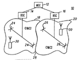
いくつかの好適な実施例、特に符号分割多重接続(CDMA)ワイヤレス通信システムに関するIS-95-A規準に準拠するワイヤレス通信システムに関して本発明を説明する。たとえば、図1を参照して、従来技術によるワイヤレス通信システム10は、移動交換センタ(MSC)12と、各々がサービス・エリア全体22のうちサービス・エリア18,20にサービスを提供する第1基地局コントローラ(BSC)14および第2BSC16とを備える。このようなシステムに関しては周知の如く、各BSC14,16はそれに接続する複数の基地トランシーバ局(BTS)24,26をそれぞれ有する。サービス・エリア18,20毎に2つのBTSしか図示されないが、必要に応じて、また本発明の正当な範囲から逸脱せずに、より多くのあるいはより少ないBTSを構築することができることは言うまでもない。MSC12,BSC14,16およびBTS24,26は、IS-95-A規準に準拠する仕様で動作し、サービス・エリア18,20内で動作する移動局(一般的に30と示す)にワイヤレス通信サービスを提供する。しかし、この場合も、本発明は構築される特定の通信規準に限られることはなく、たとえば、アナログ・セルラ,汎ヨーロッパ・デジタル化移動体通信システム(GSM)デジタル・セルラおよびIS-55時分割多重接続(TDMA:time division multile access)デジタル・セルラなどの別の規準に関しても有用である。
【0010】
BSC14に接続し、IS-95-A規準に準拠するBTSは、無線周波数チャネルすなわち搬送波C1,C2を用いてサービス・エリア18内でサービスを提供する。同様に、BSC16は、無線周波数チャネルC1,C2を用いてサービス・エリア20内でサービスを提供する。このようにしてシステム10を分割すると、サービス・エリア18と20との間にハード・ハンドオフの継ぎ目28ができる。すなわち、移動局30がサービス・エリア18からサービス・エリア20に移動すると、BSC14に伴うBTS24からBSC16に伴うBTS26への移動局30のハンドオフが必要になる。
【0011】
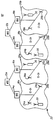
図2に、通信システム10を拡張したシステムを10’と示す。図2では、システム10の要素は文字「a」を付けて同じ番号とする。容量を拡張するために付加された要素は、文字「b」を付けて同じ番号とする。システム10’の容量は、MSC12bおよびBSC14b,16bを追加することでシステム10と比べて2倍になる。図を簡単にするために図2にはBTSを図示しないが、サービス・エリア18a,20a,18b,20bの各々においてBTSが利用されることを理解頂きたい。BSC14a,16aは、個々のサービス・エリア18a,20aにサービスを提供し続ける。BSC14b,16bは、個々のサービス・エリア18b,20bにサービスを提供する。BSC14a,16b,14b,16bは、搬送波C1,C2,C3,C4を利用してそれぞれのサービス・エリアで動作する移動局にサービスを提供する。図2でもっとも目立つのは、このようにしてシステム10をシステム10’に拡張すると、ハード・ハンドオフの継ぎ目が増えることである。ハード・ハンドオフの継ぎ目28aはBSC14a,16aの間に残り、新たな継ぎ目28bがBSC14b,16bの間に作られ、新たな継ぎ目28cがBSC16a/MSC12aおよびBSC14b/MSC12bの間に作られる。さらに、各サービス・エリアの物理的な寸法が小さくなり、ハード・ハンドオフの頻度が大きくなる。このようにして、システム10’は、2つの追加搬送波と追加装置とを付加することで容量を大きくするが、サービス・エリアが小さくなりハード・ハンドオフの継ぎ目が増える。
【0012】
次に図3を参照して、図1のシステム10が、本発明の好適な実施例により再構築されたシステム100として図示される。システム100は、搬送波C1,C2のうちの一方でサービス・エリア118,120の各々においてそれぞれサービスを提供するように構築されるBSC114,116を備える。BSC114,116は、1つの搬送波CXに対応するよう図示されるが、図示される搬送波は搬送波集合であることを理解頂きたい。たとえば、搬送波C1は搬送波CA,CB,...CNを含む搬送波集合である。しかし、搬送波集合C1,C2は、区別しなければならない。また、BSC114,116の一方が万一不良となった場合にある程度のレベルの冗長性を提供することも可能である。このような実行例においては、搬送波集合、たとえばBSC116に割り当てられる搬送波集合C2を、BSCすなわちBSC116が不良の場合に、アクティブBSCすなわちBSC114が用いることができる。これを図3に破線で示す。
【0013】
各サービス・エリア118,120の実際の寸法は、システム100のサービス・エリア全体122に対応し、各サービス・エリア118,120は、にサービス・エリア全体122と実質的に同じ物理的寸法をカバーする。BSC114,116は、それぞれ基地局124,126と結合され(図示されない適切な間隔と帰路とを利用して)、基地局124,126は両方のBSC114,116により論理的に共有されてサービス・エリア118,120のいずれかで動作する移動局30にサービスを提供する。
【0014】
図3からわかるように、システム100は、システム10に見られるハード・ハンドオフ継ぎ目なしに全サービス・エリア122にワイヤレス通信サービスを提供する。BSC114,116の各々が結合されてBTS124,126を利用し、搬送波C1またはC2またはその両方を利用するという利点が得られる。モトローラ社(イリノイ州Schaumburg)から市販されるような典型的なBTS装置は、複数搬送波機能を有する。システム100において、2搬送波BTSがBSC114,116の各々により論理的に共有される。あるいは、欠けている複数搬送波BTS,共有アンテナを利用する2つの単独搬送波BTSおよび他の無線周波数送受信ハードウェアたとえば電力増幅器,上方および下方周波数変換器などを、BSC114およびBSC116にそれぞれ結合することもできる。この後者の構造においては、複数のBTSは同じ1つの物理的位置を論理的に共有し、送受信ハードウェアを物理的に共有すると考えることができる。さらに言うまでもなく、適切な間隔と帰路(図示せず)とが提供され、BSC114,116の各々に関して区別される。
【0015】
移動局30は、適応可能なシステム規準に指定される方法でシステム100に対してアクセスする。しかし、システム100を適切な負荷分布および発散論理(load distribution and shedding logic)をもってさらに構築して、システム負荷と使用可能性とに基づいて移動局30がBSC114,116のいずれかに割り当てられる。たとえば、移動局30がシステムに対してアクセスを試み、BSC114に割り当てられる移動局が他にもある場合は、移動局30はBSC116に割り当てられることもある。BSCの割当は、移動局の種類,サービス・オプション,位置および/または現在の、あるいは予測される移動性に基づいて行われることもある。さらに、システム100内で動作する移動局30をBSC114と116との間で転送してシステムの平衡をとることもある。本発明の正当な範囲から逸脱せずに、数多くの適切な移動局割当基準が構築できることを理解頂きたい。
【0016】
次に図4を参照して、システム100は2倍の容量に拡張されたシステム100’として図示される。好適な実施例の説明では2倍の容量への拡張が論じられるが、本発明の正当な範囲から逸脱せずにより多い量または少ない量の拡張が実現できることは言うまでもない。図3に示されるシステム100’の既存の要素には、文字「a」の付いた同じ参照番号が振られる。図3に示されるのと同様であるが、システム100の容量を拡張するために追加された要素は、文字「b」の付いた同様の参照番号が振られる。
【0017】
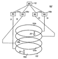
図4を引き続き参照して、システム100’は、それぞれMSC112に結合されるBSC114a,BSC116a,BSC114bおよびBSC116bを具備する。単独のMSCが図示されるが、複数のMSCを採用して容量を拡張し、システム冗長性を強化することもできる。BSC114a,116a,114b,116bの各々が、サービス・エリア全体122内の基地局(図4には図示せず)に結合されて、各サービス・エリア118a,120a,118b,120bにおいて通信サービスを提供する。言うまでもなく、また図示されるように、BSC114a,116a,114b,116bの各々は、サービス・エリア118a,120a,118b,120bの1つにおいて、C1,C2,C3,C4のうちの1つの搬送波を割り当てられる。サービス・エリア118a,120a,118b,120bは、それぞれ実質的に同じ物理的エリアすなわちサービス・エリア全体122をカバーする(サービス・エリアは、図4では明確にするために別々に図示される)。BTSは、複数搬送波BTS装置であるか、あるいは同一のアンテナと関連ハードウェアとを共有し、システム100内で同じ物理的位置を論理的に共有する単独搬送波および複数搬送波BTS装置の組み合わせとすることができる。あるいは、BSC114a,116a,114b,116bは、サービス・エリア118a,120a,118b,120bの対においてそれぞれ搬送波対を動作することもある。
【0018】
上記の如く、適切な負荷平衡および分散論理がBTSおよび/またはMSの一部として実現されるがBSCの一部として実現されることもある。移動局30は、システム100’に適用可能な規準に従ってアクセスを試み、搬送波の1つ、すなわちエリア全体122にサービスを提供するBSC114a,116a,114b,116bの1つに割り当てられる。
【0019】
システム100’は、各サービス・エリア118a,120a,118b,120bが互いに均一に重複し、サービス・エリア全体122をカバーした状態で図示される。しかし、言うまでもなく、基地局の位置と整合、アンテナ区画およびサービス・エリア構造に関する他の周知の技術に基づき、サービス・エリアがずれることもある。この構造を図5にシステム100”と図示する。ここでも、同様の参照番号を用いて、同様の要素を説明するが、互いにずれており、図5に示される共通部分132を共有するサービス・エリア118a’,120a’,118b’,120b’に対してプライム記号を付して示す。このようにして、拡張は元のカバレージ・エリア122全体を越えて延長される。あるいは、好適とされるように、共通部分132などの通信トラフィック密度が高い一部エリアにおける資源の集合により、通信資源の利用または使用可能性が強化される。
【0020】
引き続き図5を参照して、システム100と100’に関して、BSC114a,116a,114b,116bは、互いに物理的に遠隔に位置しており、それが好ましいことにさらに留意されたい。1つのBSCサイトにおいてシステム不良が起こった場合、残りのBSCを利用してサービス・エリア全体122にサービス・エリア118a,120a,118b,120bを提供することができる。容量は装置の一部の不良により小さくなるが、サービス・エリアのブラックアウトは避けられる。各サービス・エリアのBTSは、好ましくは共通基地局ハウジング内に共存しており、基地局ハウジングと共に位置するアンテナに結合される。より好ましくは、BTSは基地局ハウジング内の共通装置ラック内に位置する。
【0021】
本発明の説明全体を通じて、サービス・エリアに関する単独の通信規準が用いられる。言うまでもなく、第1エリアが第1規準による通信装置によりサービスを提供され、第2エリアが第2規準による通信装置によりサービスを提供されるシステムが構築される。たとえば、第1システムが音声通信に適応され、第2システムがデータ通信に適応される。あるいは、システムの各々が音声通信に適応されるが、異なる通信規準による音声通信に適応される。いずれの場合も、より高いレベルの通信要素が基地局装置を論理的に共有し、基地局は特定の送受信ハードウェアを物理的に共有する。
【0022】
本発明のいくつかの好適な実行例を添付の図面を参照して開示および説明した。本発明が、本明細書に説明される特定の実施例を越えた用途を有することは当業者には理解いただけよう。そのため、本発明は、図示される好適な実施例に制限されるべきではなく、制限されない。
【図面の簡単な説明】
【図1】 従来技術によるワイヤレス通信システムの概略図である。
【図2】 2倍の容量に拡張された従来技術によるワイヤレス通信システムの概略図である。
【図3】 本発明の好適な実施例により再構築された図1のワイヤレス通信システムの概略図である。
【図4】 本発明の好適な実施例により2倍の容量に拡張されたワイヤレス通信システムの概略図である。
【図5】 本発明の代替の実施例により2倍の容量に拡張されたワイヤレス通信システムの概略図である。(Industrial application fields)
The present invention relates generally to wireless communication networks, and more particularly to an increaseable wireless communication network and a method for expanding the capacity of a wireless communication network.
[0001]
(Conventional technology)
Wireless communication systems such as analog and digital cellular communication systems, personal communication systems (PCS) and other similar wireless communication systems offer great flexibility to their users. Users of wireless communication systems can be contacted almost anytime, whether on the move, at home or in the office. Also, regardless of the complexity underlying a wireless communication system, the system is easy to use for a user to dial a telephone number.
[0002]
In a wireless communication system, a user may not be able to make or receive a call or an outgoing call may be disconnected unexpectedly. It must be remembered that at least a portion of a wireless communication system is a radio frequency (RF) link between a remote or moving user and the system. There are several factors that affect how and why a call is not completed or disconnected. One reason is that the number of radio frequency resources that a particular service area can use is limited. Radio frequency resources are limited based in part on the allocation of radio frequency spectrum for a particular application. For example, a television broadcast is performed in one part of the radio frequency spectrum and a wireless communication network is assigned to another part of the radio frequency spectrum. This assignment ensures that the operation of one system does not interfere with another system due to radio frequency reuse.
[0003]
However, certain wireless communication system architectures, such as those that comply with the Interim Standard IS-95-A for Code Division Multiple Access (CDMA) wireless networks, provide the ability to use a common radio frequency for multiple users. Overcoming the limitations of radio frequency resources. Capacity issues, i.e., restrictions on users accessing and using these systems, still exist as a result of limiting the number of users that the system can handle. Of course, this can be solved by expanding the system capacity. Unfortunately, current system architectures cannot easily expand system capacity.
[0004]
For example, adding additional equipment to handle other users may seem to solve the capacity problem. However, the addition of devices creates certain system performance problems, especially in CDMA compliant wireless communication systems. For example, when additional system capacity is loaded in the form of additional base transceiver stations (BTS), base station controllers (BSC), and mobile switching centers (MSC), The gathering area covered by the MSC / BSC / BTS group becomes smaller. This means that there are more seams, i.e. the interference between the coverage areas is greater.
[0005]
The increased number of seams in the communication system means that handoffs, especially “harder” handoffs, are more frequent. Increasing seams may require more processing resources to be used, resulting in increased voice delay due to traffic interconnections and increased latency during call processing procedures. Seams require extra system engineering and often reduce call quality.
[0006]
A CDMA communication system is a process called “soft” or “softer” handoff to allow mobile stations to communicate with several BTSs and reduce the degradation of call quality caused by hard handoffs. Is adopted. Soft handoff is advantageous when the mobile station moves from an area covered by one BTS to an area covered by another BTS. During soft handoff, the mobile station is always in active communication with at least one BTS, even if it moves between BTS coverage areas. This is because each BTS operates under the control of a specific BSC using a common set of radio frequencies.
[0007]
Hard handoff seams are avoided as much as possible because they almost always adversely affect call quality. A hard handoff occurs when the mobile station moves from the area covered by the first BSC to the area covered by the second BSC. Handoff between the BTS served by the first BSC and the BTS served by the second BSC requires that a communication link be established in the second BSC via an appropriate BTS connected to the second BSC. If a handoff is required, i.e. when the mobile station moves from the service area of the first BTS to the area served by the second BTS, the mobile station must re-establish the call via the second BSC. Communication with multiple BTSs is generally not possible in this mode. More importantly, communication between the mobile station and the BTS / BSC is usually interrupted momentarily. For this reason, it must be recognized that increasing capacity in the form of additional MSCs, BSCs, and BTSs will increase the number of seams, especially hard handoff seams and the resulting service interruptions.
[0008]
Therefore, there is a need for a wireless communication system architecture that can be easily and easily expanded and expanded as the number of users of the system increases. More importantly, such system expansion is done at a minimal cost and without compromising system performance.
[0009]
(Description of preferred embodiments)
The present invention will be described in connection with some preferred embodiments, particularly wireless communication systems that comply with the IS-95-A standard for code division multiple access (CDMA) wireless communication systems. For example, referring to FIG. 1, a
[0010]
A BTS connected to the
[0011]
In FIG. 2, a system that expands the
[0012]
Referring now to FIG. 3, the
[0013]
The actual dimensions of each
[0014]
As can be seen from FIG. 3, the
[0015]
[0016]
Referring now to FIG. 4, the
[0017]
With continued reference to FIG. 4,
[0018]
As noted above, appropriate load balancing and distribution logic is implemented as part of BTS and / or MS, but may be implemented as part of BSC. The
[0019]
The
[0020]
With continued reference to FIG. 5, it should be further noted that with respect to
[0021]
Throughout the description of the invention, a single communication standard for service areas is used. Needless to say, a system is constructed in which the first area is provided with a service by a communication device according to the first standard and the second area is provided with a service by a communication device according to the second standard. For example, the first system is adapted for voice communication and the second system is adapted for data communication. Alternatively, each of the systems is adapted for voice communications, but adapted for voice communications according to different communications standards. In either case, higher level communication elements logically share the base station equipment, and the base stations physically share specific transmit / receive hardware.
[0022]
Several preferred implementations of the present invention have been disclosed and described with reference to the accompanying drawings. Those skilled in the art will appreciate that the present invention has applications beyond the specific embodiments described herein. Therefore, the present invention should not be limited to the preferred embodiments shown, but is not limited.
[Brief description of the drawings]
FIG. 1 is a schematic diagram of a wireless communication system according to the prior art.
FIG. 2 is a schematic diagram of a wireless communication system according to the prior art expanded to twice the capacity.
3 is a schematic diagram of the wireless communication system of FIG. 1 reconstructed according to a preferred embodiment of the present invention.
FIG. 4 is a schematic diagram of a wireless communication system scaled to double capacity according to a preferred embodiment of the present invention.
FIG. 5 is a schematic diagram of a wireless communication system scaled to double capacity according to an alternative embodiment of the present invention.
Claims (10)
前記通信システム・プロトコルに従って動作し、第1通信搬送波周波数とは異なる第2通信搬送波周波数を含む第2通信資源を利用する第2基地局コントローラと、
ワイヤレス通信サービス・エリア内に位置して、それにワイヤレス通信サービスを提供する複数の基地局と、前記第1通信資源および第2通信資源において前記サービス・エリア内でそれぞれ通信を行うために、前記基地局のうち第1基地局が前記第1基地局コントローラおよび第2通信基地局コントローラに結合され、および前記基地局のうち第2基地局が前記第1システム・コントローラおよび前記第2通信システム・コントローラに結合されることとを備え、
前記第1基地局のサービスを受ける移動局は、基地局コントローラおよび通信搬送波周波数のうちの少なくとも一方を変えることなくハンドオフされることが可能である、ワイヤレス通信システム。A first base station controller operating in accordance with a communication system protocol and utilizing a first communication resource including a first communication carrier frequency ;
A second base station controller that operates in accordance with the communication system protocol and utilizes a second communication resource that includes a second communication carrier frequency different from the first communication carrier frequency ;
In order to communicate with each of a plurality of base stations located in a wireless communication service area and providing a wireless communication service thereto, in the service area in the first communication resource and the second communication resource, respectively. A first base station of the stations is coupled to the first base station controller and a second communication base station controller, and a second base station of the base stations is the first system controller and the second communication system controller And being coupled to
A wireless communication system, wherein a mobile station served by the first base station can be handed off without changing at least one of a base station controller and a communication carrier frequency .
一定の通信プロトコルにしたがって動作し、および第1通信搬送波周波数を含む第1通信資源を利用する、第1の基地局コントローラを設けるステップと、
前記通信プロトコルにしたがって動作し、および第1通信搬送波周波数とは異なる第2通信搬送波周波数を含む第2通信資源を利用する、第2の基地局コントローラを設けるステップと、
前記第1の基地局コントローラおよび前記第2の基地局コントローラのそれぞれと結合されるトランシーバ局を設けるステップと、
前記第1の基地局コントローラと前記第2の基地局コントローラとの間で前記第1通信資源および第2通信資源を、前記サービスエリア内で送受信され、対応する搬送波周波数を通じて利用するためにトランシーバ局を論理的に共有するステップと、
前記第1の基地局コントローラから第2の基地局コントローラに、トランシーバ局をスイッチングすることなく移動局をハンドオフするステップとを備える、方法。A method for providing wireless communication to a wireless communication service area, comprising:
Providing a first base station controller that operates according to a fixed communication protocol and utilizes a first communication resource that includes a first communication carrier frequency ;
Providing a second base station controller that operates in accordance with the communication protocol and utilizes a second communication resource that includes a second communication carrier frequency different from the first communication carrier frequency ;
Providing a transceiver station coupled to each of the first base station controller and the second base station controller;
Said first communication resource and the second communication resources between the first base station controller and the second base station controller, the transmitted and received in the service area to available through carrier wave frequency that corresponds a step of sharing transceiver station logically,
Handing off the mobile station from the first base station controller to the second base station controller without switching a transceiver station .
前記第1の通信プロトコルに従って第1の通信搬送波とは異なる第2の通信搬送波周波数を使用する第2の複数の通信信号を制御するための第2の基地局コントローラと、
前記第1および第2の基地局コントローラのそれぞれに結合されて、第1および第2の通信資源をそれぞれ利用する前記第1および第2の複数の通信信号を、共有する通信サービスエリア内で送受信するための手段と、前記送受信するための手段からサービスを受ける移動局は、前記基地局コントローラ、前記送受信のための手段、および搬送波周波数のうちの少なくとも1つを変更することなく、基地局コントローラおよび送受信のための手段のうちの少なくとも1つを変更することとを備える、ワイヤレス通信システム。A first base station controller for controlling a first plurality of communication signals using a first communication carrier frequency according to a first communication protocol;
A second base station controller for controlling a second plurality of communication signals using a second communication carrier frequency different from the first communication carrier according to the first communication protocol;
Coupled to each of the first and second base station controllers to transmit and receive the first and second plurality of communication signals respectively using the first and second communication resources within a shared communication service area. And a mobile station receiving service from the means for transmitting and receiving the base station controller without changing at least one of the base station controller, the means for transmitting and receiving, and a carrier frequency And changing at least one of the means for transmitting and receiving .
Applications Claiming Priority (3)
| Application Number | Priority Date | Filing Date | Title |
|---|---|---|---|
| US08/994,587 | 1997-12-19 | ||
| US08/994,587 US5991628A (en) | 1997-12-19 | 1997-12-19 | Scalable wireless communication network and method |
| PCT/US1998/017481 WO1999033286A1 (en) | 1997-12-19 | 1998-08-21 | Scalable wireless communication network and method |
Publications (3)
| Publication Number | Publication Date |
|---|---|
| JP2001527355A JP2001527355A (en) | 2001-12-25 |
| JP2001527355A5 JP2001527355A5 (en) | 2006-01-26 |
| JP4174180B2 true JP4174180B2 (en) | 2008-10-29 |
Family
ID=25540827
Family Applications (1)
| Application Number | Title | Priority Date | Filing Date |
|---|---|---|---|
| JP2000526065A Expired - Lifetime JP4174180B2 (en) | 1997-12-19 | 1998-08-21 | Expandable wireless communication network and method |
Country Status (13)
| Country | Link |
|---|---|
| US (1) | US5991628A (en) |
| JP (1) | JP4174180B2 (en) |
| KR (1) | KR20010033203A (en) |
| CN (1) | CN1154370C (en) |
| BR (1) | BR9815051A (en) |
| CA (1) | CA2315793C (en) |
| DE (1) | DE19882889B4 (en) |
| FI (1) | FI118319B (en) |
| FR (1) | FR2773040B1 (en) |
| GB (1) | GB2347595B (en) |
| IL (1) | IL135998A (en) |
| SE (1) | SE522655C2 (en) |
| WO (1) | WO1999033286A1 (en) |
Families Citing this family (22)
| Publication number | Priority date | Publication date | Assignee | Title |
|---|---|---|---|---|
| US6097951A (en) * | 1997-08-06 | 2000-08-01 | Northern Telecom Limited | Method and apparatus for wireless network architecture based on subscriber distribution |
| US6148201A (en) * | 1997-08-06 | 2000-11-14 | Nortel Networks Corporation | Scalable wireless network architecture based on subscriber distribution |
| US6122513A (en) * | 1997-11-06 | 2000-09-19 | Nortel Networks Corporation | Method for extending hard-handoff boundaries within a mobile telephone communications network |
| US6243367B1 (en) * | 1997-12-31 | 2001-06-05 | Samsung Electronics Co., Ltd. | Systems and methods for providing a client-server architecture for CDMA base stations |
| US6385449B2 (en) * | 1998-03-06 | 2002-05-07 | Telefonaktiebolaget L M Ericsson | System and method used in a mobile telecommunications network for load balancing ongoing calls between different base station controllers |
| US6353742B1 (en) * | 1998-10-28 | 2002-03-05 | Motorola, Inc. | Method and apparatus for backhauling data in a communication system |
| US6341222B1 (en) * | 1998-11-04 | 2002-01-22 | Motorola, Inc. | Method and apparatus for performing selection and distribution in a communication system |
| US6263187B1 (en) * | 1999-01-08 | 2001-07-17 | Lucent Technologies Inc. | Obtaining data for calls made by a specific/cellular mobile station |
| WO2001026396A1 (en) * | 1999-09-30 | 2001-04-12 | Fujitsu Limited | Mobile communication system |
| CA2327761A1 (en) * | 1999-12-21 | 2001-06-21 | Lucent Technologies Inc. | Wireless systems combining arrangement and method thereof |
| KR100659198B1 (en) * | 2000-05-17 | 2006-12-21 | 유티스타콤코리아 유한회사 | A base station system in mobile communication system |
| US8363744B2 (en) | 2001-06-10 | 2013-01-29 | Aloft Media, Llc | Method and system for robust, secure, and high-efficiency voice and packet transmission over ad-hoc, mesh, and MIMO communication networks |
| US6909879B1 (en) * | 2000-08-22 | 2005-06-21 | Cellco Partnership | Methods and apparatus for utilizing radio frequency spectrum simultaneously and concurrently in the presence of co-channel and/or adjacent channel television signals |
| SE518230C2 (en) * | 2000-12-12 | 2002-09-10 | Fredriksson Lars Berno | Mobile data and communication network for i.a. indoor use with frequency jump and time slot reuse |
| US20020193105A1 (en) * | 2001-06-13 | 2002-12-19 | Olsson John Gunnar | Dynamic Handling of orphan cells |
| US7043270B2 (en) | 2001-08-13 | 2006-05-09 | Andrew Corporation | Shared tower system for accomodating multiple service providers |
| US7346023B2 (en) * | 2001-08-22 | 2008-03-18 | Lucent Technologies Inc. | Reconfigurable wireless communication access system and method |
| JP3896848B2 (en) * | 2001-12-27 | 2007-03-22 | 日本電気株式会社 | CDMA cellular system |
| TWI320666B (en) | 2002-04-12 | 2010-02-11 | Interdigital Tech Corp | An access burst detector for use in a node b/base station |
| US7359709B2 (en) * | 2004-06-29 | 2008-04-15 | Qualcomm, Incorporated | Methods and apparatus for inter-BSC soft handoff |
| US20080123610A1 (en) * | 2006-11-29 | 2008-05-29 | Prasanna Desai | Method and system for a shared antenna control using the output of a voice activity detector |
| WO2010101529A1 (en) * | 2009-03-03 | 2010-09-10 | Agency For Science, Technology And Research | A method of communication |
Family Cites Families (9)
| Publication number | Priority date | Publication date | Assignee | Title |
|---|---|---|---|---|
| US4775998A (en) * | 1987-07-20 | 1988-10-04 | Motorola, Inc. | Cellular radiotelephone system having colocated base sites |
| US5093925A (en) * | 1990-04-25 | 1992-03-03 | Motorola, Inc. | Three dimensional cellular communication system with coordinate offset and frequency reuse |
| FI88660C (en) * | 1991-01-09 | 1993-06-10 | Nokia Telecommunications Oy | Radiosändarmottagarsystem |
| US5208847A (en) * | 1991-02-25 | 1993-05-04 | Northern Telecom Limited | Method of increasing capacity of cellular network |
| WO1995020865A1 (en) * | 1994-01-27 | 1995-08-03 | Nokia Telecommunications Oy | Semi-hard handoff in a cellular telecommunications system |
| US5697055A (en) * | 1994-10-16 | 1997-12-09 | Qualcomm Incorporated | Method and apparatus for handoff between different cellular communications systems |
| US5592480A (en) * | 1995-03-13 | 1997-01-07 | Carney; Ronald R. | Wideband wireless basestation making use of time division multiple-access bus having selectable number of time slots and frame synchronization to support different modulation standards |
| US5781865A (en) * | 1996-05-20 | 1998-07-14 | Scientific Research Corporation | PCS cell site system for allowing a plurality of PCS providers to share cell site antennas |
| GB2320653A (en) * | 1996-12-23 | 1998-06-24 | Northern Telecom Ltd | Mobile Communications Network Using Alternative Protocols |
-
1997
- 1997-12-19 US US08/994,587 patent/US5991628A/en not_active Expired - Lifetime
-
1998
- 1998-08-21 BR BR9815051-0A patent/BR9815051A/en not_active Application Discontinuation
- 1998-08-21 DE DE19882889T patent/DE19882889B4/en not_active Expired - Lifetime
- 1998-08-21 GB GB0013053A patent/GB2347595B/en not_active Expired - Lifetime
- 1998-08-21 CN CNB988122138A patent/CN1154370C/en not_active Expired - Lifetime
- 1998-08-21 CA CA002315793A patent/CA2315793C/en not_active Expired - Lifetime
- 1998-08-21 JP JP2000526065A patent/JP4174180B2/en not_active Expired - Lifetime
- 1998-08-21 KR KR1020007006595A patent/KR20010033203A/en active Search and Examination
- 1998-08-21 WO PCT/US1998/017481 patent/WO1999033286A1/en not_active Application Discontinuation
- 1998-08-21 IL IL13599898A patent/IL135998A/en not_active IP Right Cessation
- 1998-10-05 FR FR9812423A patent/FR2773040B1/en not_active Expired - Lifetime
-
2000
- 2000-06-14 FI FI20001414A patent/FI118319B/en not_active IP Right Cessation
- 2000-06-15 SE SE0002226A patent/SE522655C2/en not_active IP Right Cessation
Also Published As
| Publication number | Publication date |
|---|---|
| GB0013053D0 (en) | 2000-07-19 |
| FI118319B (en) | 2007-09-28 |
| BR9815051A (en) | 2000-10-03 |
| GB2347595B (en) | 2002-12-18 |
| CA2315793A1 (en) | 1999-07-01 |
| JP2001527355A (en) | 2001-12-25 |
| FI20001414A (en) | 2000-06-14 |
| WO1999033286A1 (en) | 1999-07-01 |
| SE522655C2 (en) | 2004-02-24 |
| CA2315793C (en) | 2003-06-03 |
| IL135998A0 (en) | 2001-05-20 |
| FR2773040A1 (en) | 1999-06-25 |
| FR2773040B1 (en) | 2000-10-13 |
| CN1154370C (en) | 2004-06-16 |
| CN1282491A (en) | 2001-01-31 |
| US5991628A (en) | 1999-11-23 |
| SE0002226D0 (en) | 2000-06-15 |
| DE19882889B4 (en) | 2010-10-07 |
| IL135998A (en) | 2004-07-25 |
| GB2347595A (en) | 2000-09-06 |
| SE0002226L (en) | 2000-08-16 |
| DE19882889T1 (en) | 2001-04-12 |
| KR20010033203A (en) | 2001-04-25 |
Similar Documents
| Publication | Publication Date | Title |
|---|---|---|
| JP4174180B2 (en) | Expandable wireless communication network and method | |
| EP0815697B1 (en) | Distributed radio telecommunications system | |
| JP4268634B2 (en) | Method and system for integrating resource allocation between TDD and FDD in a wireless communication system | |
| JP4388704B2 (en) | Time sharing of communication resources in cellular communication systems. | |
| KR100796818B1 (en) | System and method for performing soft handoff between frequency division duplex and time division duplex communication systems | |
| KR100276810B1 (en) | Client-Server Architecture Implementation Method and Method for CDA Base Station | |
| EP0652644B1 (en) | Base station transmission-reception apparatus for cellular system | |
| US20020004371A1 (en) | Method of signaling compressed mode parameters to a mobile station | |
| KR20020014840A (en) | Radio communication system and communication terminal apparatus used therein | |
| EP1060570A1 (en) | Wireless co-tenant base station | |
| CA2275305A1 (en) | Transceiver hopping | |
| CN100502552C (en) | Relay apparatus and system for implementing fast switching | |
| US20020077149A1 (en) | Wireless network infrastructure in that digital processing resources are shared | |
| JP2007507180A (en) | Method and system for integrating resource allocation between TDD and FDD in a wireless communication system | |
| US7127273B2 (en) | Reduction scheme for network elements | |
| EP1387599A1 (en) | Improved channelisation code management for softer handover in CDMA mobile communications systems | |
| KR100524000B1 (en) | Sectorization method of smart antenna base station system, storing medium and asynchronous imt-2000 thereof | |
| JP2002369244A (en) | Small-capacity base station control system for cdma mobile communication system, and method therefor | |
| EP1004216A1 (en) | Method of sending time slots in base station system and such a system |
Legal Events
| Date | Code | Title | Description |
|---|---|---|---|
| A621 | Written request for application examination |
Free format text: JAPANESE INTERMEDIATE CODE: A621 Effective date: 20050822 |
|
| A521 | Request for written amendment filed |
Free format text: JAPANESE INTERMEDIATE CODE: A523 Effective date: 20051202 |
|
| A131 | Notification of reasons for refusal |
Free format text: JAPANESE INTERMEDIATE CODE: A131 Effective date: 20071106 |
|
| A601 | Written request for extension of time |
Free format text: JAPANESE INTERMEDIATE CODE: A601 Effective date: 20080206 |
|
| A602 | Written permission of extension of time |
Free format text: JAPANESE INTERMEDIATE CODE: A602 Effective date: 20080214 |
|
| A521 | Request for written amendment filed |
Free format text: JAPANESE INTERMEDIATE CODE: A523 Effective date: 20080507 |
|
| TRDD | Decision of grant or rejection written | ||
| A01 | Written decision to grant a patent or to grant a registration (utility model) |
Free format text: JAPANESE INTERMEDIATE CODE: A01 Effective date: 20080722 |
|
| A01 | Written decision to grant a patent or to grant a registration (utility model) |
Free format text: JAPANESE INTERMEDIATE CODE: A01 |
|
| A61 | First payment of annual fees (during grant procedure) |
Free format text: JAPANESE INTERMEDIATE CODE: A61 Effective date: 20080818 |
|
| R150 | Certificate of patent or registration of utility model |
Free format text: JAPANESE INTERMEDIATE CODE: R150 Ref document number: 4174180 Country of ref document: JP Free format text: JAPANESE INTERMEDIATE CODE: R150 |
|
| FPAY | Renewal fee payment (event date is renewal date of database) |
Free format text: PAYMENT UNTIL: 20110822 Year of fee payment: 3 |
|
| FPAY | Renewal fee payment (event date is renewal date of database) |
Free format text: PAYMENT UNTIL: 20110822 Year of fee payment: 3 |
|
| S111 | Request for change of ownership or part of ownership |
Free format text: JAPANESE INTERMEDIATE CODE: R313111 |
|
| FPAY | Renewal fee payment (event date is renewal date of database) |
Free format text: PAYMENT UNTIL: 20110822 Year of fee payment: 3 |
|
| FPAY | Renewal fee payment (event date is renewal date of database) |
Free format text: PAYMENT UNTIL: 20120822 Year of fee payment: 4 |
|
| R250 | Receipt of annual fees |
Free format text: JAPANESE INTERMEDIATE CODE: R250 |
|
| FPAY | Renewal fee payment (event date is renewal date of database) |
Free format text: PAYMENT UNTIL: 20120822 Year of fee payment: 4 |
|
| R350 | Written notification of registration of transfer |
Free format text: JAPANESE INTERMEDIATE CODE: R350 |
|
| FPAY | Renewal fee payment (event date is renewal date of database) |
Free format text: PAYMENT UNTIL: 20120822 Year of fee payment: 4 |
|
| S533 | Written request for registration of change of name |
Free format text: JAPANESE INTERMEDIATE CODE: R313533 |
|
| R250 | Receipt of annual fees |
Free format text: JAPANESE INTERMEDIATE CODE: R250 |
|
| FPAY | Renewal fee payment (event date is renewal date of database) |
Free format text: PAYMENT UNTIL: 20130822 Year of fee payment: 5 |
|
| R350 | Written notification of registration of transfer |
Free format text: JAPANESE INTERMEDIATE CODE: R350 |
|
| R250 | Receipt of annual fees |
Free format text: JAPANESE INTERMEDIATE CODE: R250 |
|
| R250 | Receipt of annual fees |
Free format text: JAPANESE INTERMEDIATE CODE: R250 |
|
| R250 | Receipt of annual fees |
Free format text: JAPANESE INTERMEDIATE CODE: R250 |
|
| S111 | Request for change of ownership or part of ownership |
Free format text: JAPANESE INTERMEDIATE CODE: R313113 |
|
| S531 | Written request for registration of change of domicile |
Free format text: JAPANESE INTERMEDIATE CODE: R313531 |
|
| R350 | Written notification of registration of transfer |
Free format text: JAPANESE INTERMEDIATE CODE: R350 |
|
| R250 | Receipt of annual fees |
Free format text: JAPANESE INTERMEDIATE CODE: R250 |
|
| R250 | Receipt of annual fees |
Free format text: JAPANESE INTERMEDIATE CODE: R250 |
|
| EXPY | Cancellation because of completion of term |