JP4173151B2 - Conveyor chain - Google Patents
Conveyor chain Download PDFInfo
- Publication number
- JP4173151B2 JP4173151B2 JP2005150034A JP2005150034A JP4173151B2 JP 4173151 B2 JP4173151 B2 JP 4173151B2 JP 2005150034 A JP2005150034 A JP 2005150034A JP 2005150034 A JP2005150034 A JP 2005150034A JP 4173151 B2 JP4173151 B2 JP 4173151B2
- Authority
- JP
- Japan
- Prior art keywords
- chain
- ball
- free
- chain link
- conveyor
- Prior art date
- Legal status (The legal status is an assumption and is not a legal conclusion. Google has not performed a legal analysis and makes no representation as to the accuracy of the status listed.)
- Active
Links
- 229930182556 Polyacetal Natural products 0.000 claims description 16
- 229920006324 polyoxymethylene Polymers 0.000 claims description 16
- 239000004952 Polyamide Substances 0.000 claims description 13
- 229920002647 polyamide Polymers 0.000 claims description 13
- 229920000728 polyester Polymers 0.000 claims description 11
- 239000000463 material Substances 0.000 description 6
- 239000000428 dust Substances 0.000 description 4
- 238000012423 maintenance Methods 0.000 description 4
- 230000000694 effects Effects 0.000 description 3
- 230000002950 deficient Effects 0.000 description 2
- 230000001747 exhibiting effect Effects 0.000 description 2
- 229920001707 polybutylene terephthalate Polymers 0.000 description 2
- -1 polyethylene terephthalate Polymers 0.000 description 2
- 229920000139 polyethylene terephthalate Polymers 0.000 description 2
- 239000005020 polyethylene terephthalate Substances 0.000 description 2
- 239000000843 powder Substances 0.000 description 2
- 229920002292 Nylon 6 Polymers 0.000 description 1
- 229920002302 Nylon 6,6 Polymers 0.000 description 1
- 229920001400 block copolymer Polymers 0.000 description 1
- 229920001577 copolymer Polymers 0.000 description 1
- 238000010586 diagram Methods 0.000 description 1
- 229920006351 engineering plastic Polymers 0.000 description 1
- 229920001519 homopolymer Polymers 0.000 description 1
- 238000009434 installation Methods 0.000 description 1
- 229920000642 polymer Polymers 0.000 description 1
- 229920003002 synthetic resin Polymers 0.000 description 1
- 239000000057 synthetic resin Substances 0.000 description 1
Images


Classifications
-
- B—PERFORMING OPERATIONS; TRANSPORTING
- B65—CONVEYING; PACKING; STORING; HANDLING THIN OR FILAMENTARY MATERIAL
- B65G—TRANSPORT OR STORAGE DEVICES, e.g. CONVEYORS FOR LOADING OR TIPPING, SHOP CONVEYOR SYSTEMS OR PNEUMATIC TUBE CONVEYORS
- B65G17/00—Conveyors having an endless traction element, e.g. a chain, transmitting movement to a continuous or substantially-continuous load-carrying surface or to a series of individual load-carriers; Endless-chain conveyors in which the chains form the load-carrying surface
- B65G17/30—Details; Auxiliary devices
- B65G17/38—Chains or like traction elements; Connections between traction elements and load-carriers
- B65G17/40—Chains acting as load-carriers
-
- B—PERFORMING OPERATIONS; TRANSPORTING
- B65—CONVEYING; PACKING; STORING; HANDLING THIN OR FILAMENTARY MATERIAL
- B65G—TRANSPORT OR STORAGE DEVICES, e.g. CONVEYORS FOR LOADING OR TIPPING, SHOP CONVEYOR SYSTEMS OR PNEUMATIC TUBE CONVEYORS
- B65G17/00—Conveyors having an endless traction element, e.g. a chain, transmitting movement to a continuous or substantially-continuous load-carrying surface or to a series of individual load-carriers; Endless-chain conveyors in which the chains form the load-carrying surface
- B65G17/24—Conveyors having an endless traction element, e.g. a chain, transmitting movement to a continuous or substantially-continuous load-carrying surface or to a series of individual load-carriers; Endless-chain conveyors in which the chains form the load-carrying surface comprising a series of rollers which are moved, e.g. over a supporting surface, by the traction element to effect conveyance of loads or load-carriers
-
- B—PERFORMING OPERATIONS; TRANSPORTING
- B65—CONVEYING; PACKING; STORING; HANDLING THIN OR FILAMENTARY MATERIAL
- B65G—TRANSPORT OR STORAGE DEVICES, e.g. CONVEYORS FOR LOADING OR TIPPING, SHOP CONVEYOR SYSTEMS OR PNEUMATIC TUBE CONVEYORS
- B65G2201/00—Indexing codes relating to handling devices, e.g. conveyors, characterised by the type of product or load being conveyed or handled
- B65G2201/02—Articles
-
- B—PERFORMING OPERATIONS; TRANSPORTING
- B65—CONVEYING; PACKING; STORING; HANDLING THIN OR FILAMENTARY MATERIAL
- B65G—TRANSPORT OR STORAGE DEVICES, e.g. CONVEYORS FOR LOADING OR TIPPING, SHOP CONVEYOR SYSTEMS OR PNEUMATIC TUBE CONVEYORS
- B65G2207/00—Indexing codes relating to constructional details, configuration and additional features of a handling device, e.g. Conveyors
- B65G2207/30—Modular constructions
Landscapes
- Engineering & Computer Science (AREA)
- Mechanical Engineering (AREA)
- Chain Conveyers (AREA)
- Rollers For Roller Conveyors For Transfer (AREA)
Description
本発明は、平坦な底面を備えた箱状、板状等の物品を載荷して搬送するのに適したコンベヤチェーンに関するものであって、特に、チェーンリンクの表裏両面に突出して回転するフリーボールを保持させたコンベヤチェーンに関する。 The present invention relates to a conveyor chain suitable for loading and transporting a box-like or plate-like article having a flat bottom surface, and in particular, a free ball that protrudes and rotates on both front and back sides of a chain link. It is related with the conveyor chain which hold | maintained.
従来、物品を載荷して搬送するコンベヤチェーンとして、複数のベルトモジュールに回転自在なボール又はローラを設けて、搬送途上で物品を仕分けするなど捌いて搬送ラインの側方に滑動排出するようにするとともに倍速機能を付与したコンベヤベルトがある(特許文献1参照)。 Conventionally, as a conveyor chain for loading and transporting articles, a plurality of belt modules are provided with rotatable balls or rollers so as to sort the articles during transportation and slide them to the side of the transportation line. In addition, there is a conveyor belt provided with a double speed function (see Patent Document 1).
そして、このようなコンベヤベルトは、物品を載荷して搬送するベルトモジュールが上下に重ねて合体した第1部材と第2部材とにそれぞれ形成されたヒンジ部をヒンジピンで連結したものであって、これらの第1部材と第2部材との間に搬送ラインの側方に滑動排出するため、ボールまたはローラが回転可能に保持されている。
しかしながら、前述したような従来のコンベヤチェーンであるコンベヤベルトは、上下方向から合体する第1部材と第2部材とでベルトモジュールを構成するとともに、ボールは、第1と第2の部材との間に挟持されているため、ベルトモジュールとボールとの間で摺動摩耗が発生する。 However, the conveyor belt, which is a conventional conveyor chain as described above, forms a belt module with the first member and the second member that are combined from above and below, and the ball is between the first and second members. Therefore, sliding wear occurs between the belt module and the ball.
そこで、このようなコンベヤベルトでは、自己潤滑性に優れたポリアセタールでベルトモジュールとボールを作製して摺動摩耗を抑制することも行われているが、同種材料の組み合わせであるので接触面は親和性が高く凝着し易いため、摺動摩耗を十分に抑制することができない。
そのため、このような同種の材料で作製されたベルトモジュールやボールは摩耗が促進されてコンベヤベルトのガタツキや搬送レベルの変動が発生し、ボール上に載置した物品を安定して搬送し難いという問題があり、また、この摺動摩耗により発生する粉塵により搬送環境を汚染しやすいという問題もあった。
In such conveyor belts, belt modules and balls are made of polyacetal with excellent self-lubricating properties to suppress sliding wear, but the contact surface is compatible because of the combination of the same materials. Because of its high performance and easy adhesion, sliding wear cannot be sufficiently suppressed.
For this reason, the belt modules and balls made of the same kind of material are accelerated in wear, causing rattling of the conveyor belt and fluctuations in the conveyance level, and it is difficult to stably convey the articles placed on the balls. There is also a problem, and there is also a problem that the conveyance environment is easily contaminated by dust generated by this sliding wear.
そこで、本発明は、前述したような従来技術の問題を解決するものであって、すなわち、本発明の目的は、フリーボールを全方向に回転可能に保持して360度の全水平面内で搬送可能な搬送方向転換機能と倍速機能を発揮させるとともに、フリーボール及びこのフリーボールを保持するリテーナの摩耗を抑制して物品を安定して搬送することができ、しかも、フリーボールやリテーナが摩耗した場合であっても摩耗したボールユニットを取り外し自在に交換できるとともにチェーンリンクの材質も自由に選択でき、保守管理が容易なコンベヤチェーンを提供することである。 Therefore, the present invention solves the problems of the prior art as described above. That is, the object of the present invention is to hold a free ball so that it can rotate in all directions and transport it in a 360-degree horizontal plane. In addition to exhibiting possible transfer direction change function and double speed function, it is possible to stably transport articles by suppressing wear of free balls and retainers holding these free balls, and free balls and retainers are worn Even in such a case, it is possible to provide a conveyor chain in which a worn ball unit can be detachably replaced and a material of a chain link can be freely selected and maintenance is easy.
本請求項1に係る発明は、物品を載荷する物品載荷部と該物品載荷部の前方端縁と後方端縁から千鳥状に突出する複数のヒンジ部とを一体成形した多数のチェーンリンクがヒンジピンを介してチェーン長手方向にそれぞれ連結されているとともに、前記チェーンリンクの表裏両面に突出して回転させるフリーボールを上下一対のリテーナに挟み込んで保持してなるボールユニットが前記チェーンリンクのヒンジ部間に設けられたユニット装着領域にチェーン長手方向からそれぞれ装着されているコンベヤチェーンであって、前記フリーボールと該フリーボールを保持するリテーナのいずれか一方が、ポリアセタールで形成され、他方がポリアミドまたはポリエステルで形成されていることにより、前記課題を解決したものである。 According to the first aspect of the present invention, a large number of chain links integrally formed of an article loading portion for loading an article, and a plurality of hinge portions protruding in a staggered manner from the front edge and the rear edge of the article loading portion are hinge pins. Are connected to each other in the longitudinal direction of the chain, and a ball unit that holds and holds free balls that protrude and rotate on both front and back surfaces of the chain link between a pair of upper and lower retainers is provided between the hinge portions of the chain links. It is a conveyor chain that is mounted on the provided unit mounting area from the longitudinal direction of the chain, and either one of the free ball and the retainer that holds the free ball is formed of polyacetal, and the other is made of polyamide or polyester. By being formed, the said subject is solved.
本請求項2に係る発明のコンベヤチェーンは、請求項1に記載の構成に加え、前記ボールユニットが、前記チェーンリンクに着脱自在に形成されていることにより、前記課題を解決したものである。 A conveyor chain according to a second aspect of the present invention solves the above-mentioned problem by the ball unit being detachably formed on the chain link in addition to the configuration of the first aspect.
本請求項3に係る発明は、請求項1または請求項2に記載の構成に加え、前記リテーナのボール受け面が、複数のリブまたは溝を備えていることにより、前記課題を解決したものである。 The invention according to claim 3 solves the above-mentioned problem by providing the ball receiving surface of the retainer with a plurality of ribs or grooves in addition to the configuration according to claim 1 or claim 2. is there.
本請求項1に係る発明のコンベヤチェーンは、物品を載荷する物品載荷部と該物品載荷部の前方端縁と後方端縁から千鳥状に突出する複数のヒンジ部とを一体成形した多数の多数のチェーンリンクがヒンジピンを介してチェーン長手方向にそれぞれ連結されているので、平坦な底面を備えた箱状、板状等の物品を搬送できるとともに、チェーンリンクの表裏両面に突出して回転するフリーボールが保持されて、前記の物品を360度の全水平面内で搬送可能な搬送方向転換機能と倍速機能を発揮できる。
そして、チェーンリンクの表裏両面に突出して回転させるフリーボールを上下一対のリテーナに挟み込んで保持してなるボールユニットが前記チェーンリンクのヒンジ部間に設けられたユニット装着領域にチェーン長手方向からそれぞれ装着されていることにより、チェーンリンクへの装着を簡便に行うことができ、しかも、フリーボールやリテーナが摩耗しても、摩耗したボールユニットを取り外して交換できるので、保守管理が容易であり、チェーンリンクの材質も自由に選択できる。
The conveyor chain according to the first aspect of the present invention includes a large number of integrally formed article loading portions on which articles are loaded and a plurality of hinge portions protruding in a staggered manner from the front edge and the rear edge of the article loading portion. The chain links are connected to each other in the longitudinal direction of the chain via hinge pins, so that it is possible to transport box-like, plate-like articles with a flat bottom surface, and to rotate freely protruding from both the front and back sides of the chain link Is maintained, and the conveyance direction changing function and the double speed function capable of conveying the article in the entire horizontal plane of 360 degrees can be exhibited.
A ball unit that holds and holds free balls that protrude and rotate on both front and back sides of the chain link between a pair of upper and lower retainers is mounted on the unit mounting area provided between the hinge portions of the chain link from the longitudinal direction of the chain. As a result, it can be easily attached to the chain link, and even if the free ball or retainer wears, the worn ball unit can be removed and replaced, making maintenance and maintenance easy. The material of the link can be selected freely.
また、フリーボール及びこのフリーボールを保持するリテーナのいずれか一方がポリアセタールで形成され、他方がポリアミドまたはポリエステルで形成されているので、フリーボール及びボール保持部の摩耗を抑制できる。
すなわち、ポリアセタール、ポリアミド及びポリエステルは、自己潤滑性に優れ、しかも、フリーボールとこのフリーボールを保持するリテーナとが異種材料の接触となるため、同種材料同士のそれよりも摩擦係数を小さくでき、さらに、フリーボールとリテーナと間で起こる摺動摩耗を抑制できる。
そのため、フリーボールやリテーナの摩耗によるボール径の変化を抑えることができるので、搬送物品の底部の破損や変形を防止できるととともに、搬送レベルの変動が抑制されて安定した搬送を実現できる。
さらに、フリーボールやリテーナの摩耗が抑制されるので、摩耗粉の発生が少なく、搬送環境のクリーン化を図ることができる。
In addition, since either the free ball or the retainer that holds the free ball is formed of polyacetal and the other is formed of polyamide or polyester, wear of the free ball and the ball holding portion can be suppressed.
That is, polyacetal, polyamide and polyester are excellent in self-lubricating properties, and because the free ball and the retainer holding the free ball are in contact with different materials, the friction coefficient can be made smaller than that between the same materials, Furthermore, sliding wear that occurs between the free ball and the retainer can be suppressed.
Therefore, the change in the ball diameter due to the wear of the free ball or the retainer can be suppressed, so that the bottom of the transported article can be prevented from being damaged or deformed, and the transport level can be prevented from fluctuating and stable transport can be realized.
Furthermore, since wear of free balls and retainers is suppressed, the generation of wear powder is small, and the transport environment can be cleaned.
本請求項2に係る発明は、請求項1に記載の発明が奏する効果に加え、前記ボールユニットがチェーンリンクに着脱自在に形成されていることにより、予めフリーボールを上下一対のリテーナに挟み込んで保持してなるボールユニットをチェーンリンクへ簡便に装着でき、また、リテーナやフリーボールが摩耗しても、摩耗したボールユニットを取り外して交換でき、コンベヤチェーンの保守管理が容易である。 In addition to the effect of the invention according to claim 1, the invention according to claim 2 is configured such that the free ball is previously sandwiched between a pair of upper and lower retainers by the ball unit being detachably formed on the chain link. The held ball unit can be easily attached to the chain link, and even if the retainer or free ball wears, the worn ball unit can be removed and replaced, and the maintenance management of the conveyor chain is easy.
本請求項3に係る発明は、請求項1または請求項2に記載の発明が奏する効果に加え、前記リテーナのボール受け面が、複数のリブまたは溝を備えていることにより、摩耗粉や塵埃をリブ間または溝から排出してフリーボールの回転不良や回転不良による偏摩耗を抑制できるため、フリーボールの回転をスムースにして、安定した搬送をさらに高めることができる。 In addition to the effect of the invention according to claim 1 or 2, the invention according to claim 3 is provided with a plurality of ribs or grooves on the ball receiving surface of the retainer. Since the free balls can be discharged from the ribs or from the grooves to prevent uneven rotation due to the rotation failure of the free balls and rotation failure, the rotation of the free balls can be made smooth to further improve the stable conveyance.
本発明は、物品を載荷する物品載荷部と該物品載荷部の前方端縁と後方端縁から千鳥状に突出する複数のヒンジ部とを一体成形した多数のチェーンリンクがヒンジピンを介してチェーン長手方向にそれぞれ連結されているとともに、前記チェーンリンクの表裏両面に突出して回転させるフリーボールを上下一対のリテーナに挟み込んで保持してなるボールユニットが前記チェーンリンクのヒンジ部間に設けられたユニット装着領域にチェーン長手方向からそれぞれ装着されているコンベヤチェーンであって、前記フリーボールと該フリーボールを保持するリテーナのいずれか一方が、ポリアセタールで形成され、他方がポリアミドまたはポリエステルで形成されていることにより、コンベヤチェーンに保持したフリーボールを全方向に回転可能にして360度の全水平面内で搬送可能な搬送方向転換機能と倍速機能を発揮することができるとともに、フリーボール及びリテーナの摩耗を抑制して安定した搬送を行うことができるものであれば、その具体的態様は如何なるものであっても構わない。 In the present invention, a large number of chain links integrally formed with an article loading portion for loading an article, and a plurality of hinge portions protruding in a staggered manner from the front edge and the rear edge of the article loading portion are formed in the longitudinal direction of the chain via hinge pins. A unit mounted on the chain link between the hinges of the chain link, each of which is connected in a direction and holds a free ball that protrudes and rotates on both the front and back surfaces of the chain link between a pair of upper and lower retainers. Conveyor chains that are respectively attached to the region from the longitudinal direction of the chain, wherein either one of the free balls and the retainer that holds the free balls is formed of polyacetal, and the other is formed of polyamide or polyester. Allows free balls held on the conveyor chain to rotate in all directions As long as it can exhibit a transfer direction change function and a double speed function that can be transferred in a 360-degree all horizontal plane, and can suppress the wear of free balls and retainers and perform stable transfer, The specific aspect may be anything.
すなわち、本発明のコンベヤチェーンに用いたチェーンリンクは、搬送ラインのライン幅に応じた如何なるリンク幅であっても良く、物品載荷部に形成される載荷可能部分の寸法やヒンジ部の突出部分の寸法などについてもチェーンリンクのチェーンピッチなどに応じて適宜定めたものを採用することができる。
また、コンベヤチェーンに装着されるフリーボールの個数は、360度の全水平面内で搬送可能な搬送方向転換機能を発揮できれば、如何様な個数であっても良いが、好ましくは、フリーボールを500〜3000個/m2でとなるように配置すると、ボール1個当たりにかかる負荷が少ないため、フリーボールの摩耗やクリープによる径の変形量が小さくなり、搬送物品底部の破損や変形を防止できるとともに安定した搬送を高めることができる。
That is, the chain link used in the conveyor chain of the present invention may have any link width corresponding to the line width of the conveyance line, and the dimensions of the loadable portion formed on the article loading portion and the protruding portion of the hinge portion. Regarding dimensions and the like, those appropriately determined according to the chain pitch of the chain link can be adopted.
Further, the number of free balls mounted on the conveyor chain may be any number as long as it can exhibit a transfer direction changing function that can be transferred in a 360-degree horizontal plane. When placed at 3,000 / m2, since the load per ball is small, the amount of deformation of the diameter due to free ball wear and creep is reduced, and damage and deformation of the bottom of the conveyed product can be prevented. Stable conveyance can be enhanced.
そして、フリーボールとボール保持部となるリテーナは、一方がポリアセタールで形成され、他方がポリアミドまたはポリエステルで形成されていればよく、ポリアセタールとしては、ホモポリマー、コポリマーあるいはブロックコポリマーの何れであっても良く、ポリアミドとしては、ナイロン6、ナイロン66等何れであっても良く、ポリエステルとしては、ポリエチレンテレフタレート(PET)、ポリブチレンテレフタレート(PBT)等何れでも良い。 The retainer to be the free ball and the ball holding portion may be formed of one of polyacetal and the other of polyamide or polyester, and the polyacetal may be any of homopolymer, copolymer or block copolymer. The polyamide may be nylon 6 or nylon 66, and the polyester may be polyethylene terephthalate (PET) or polybutylene terephthalate (PBT).
このボールユニットは、如何なるユニット形態であっても良く、好ましくは、上下対称となる上下一対のリテーナとの間にフリーボールを挟み込んで保持した状態で、フリーボールがチェーンリンクの表裏両面に突出して回転するように構成すると良い。このように、上下対称とすると、ボールユニットを上下ランダムにチェーンリンクに装着できるので、装着作業を効率よく行うことができる。 This ball unit may take any unit form. Preferably, the free ball protrudes from both the front and back sides of the chain link in a state where the free ball is sandwiched and held between a pair of upper and lower retainers that are vertically symmetrical. It is good to comprise so that it may rotate. Thus, if it is symmetrical vertically, the ball unit can be mounted on the chain link randomly in the vertical direction, so that the mounting work can be performed efficiently.
本発明の一実施例であるコンベヤチェーンを図1乃至図4に基づいて説明する。
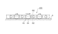
図1は、本実施例であるコンベヤチェーンの一部を表面側からみた概要説明図であり、図2は、図1に示すチェーンリンク裏面側からみた斜視図であり、図3は、ボールユニットの分解組み立て図であり、図4は、コンベヤチェーンの作動状態を示す説明図である。
A conveyor chain according to an embodiment of the present invention will be described with reference to FIGS.
FIG. 1 is a schematic explanatory view of a part of a conveyor chain according to the present embodiment as seen from the front side, FIG. 2 is a perspective view seen from the back side of the chain link shown in FIG. 1, and FIG. FIG. 4 is an explanatory view showing an operating state of the conveyor chain.
本実施例のコンベヤチェーン100は、図1に示すように、物品を載荷する物品載荷部と該物品載荷部111の前方端縁と後方端縁から千鳥状に突出する複数のヒンジ部112とを一体成形した多数のチェーンリンク110がヒンジ部112に設けられたピン孔116にヒンジピン120を挿通することにより、すなわち、ヒンジピン120を介してチェーン長手方向に相互に多数連結されており、チェーンリンク110に形成されたユニット装着領域113にフリーボール131がボールユニット130の形で装着され、すなわち、フリーボール131がチェーンリンク110に保持されて平坦な底面を備えた箱状、板状等の物品をフリーボール131上に載荷して搬送するように構成したものである。
As shown in FIG. 1, the
なお、本実施例では、チェーン幅方向を1つのチェーンリンクで構成しているが、同一リンク幅のチェーンリンクをチェーン幅方向に複数列編成して構成しても良く、さらに、リンク幅の異なるチェーンリンクをチェーン幅方向に突き合わせてチェーン長手方向に煉瓦積みのように連結して突き合わせ面がチェーン長手方向に整列しないようにしても構わない。 In this embodiment, the chain width direction is constituted by one chain link. However, chain links having the same link width may be formed in a plurality of rows in the chain width direction, and the link widths are different. The chain links may be butted in the chain width direction and connected in the longitudinal direction of the chain like brickwork so that the butted surfaces are not aligned in the longitudinal direction of the chain.
ここで、前記チェーンリンク110は、図1に示すように、前方端縁と後方端縁から千鳥状に突出する複数のヒンジ部112と、一方の縁端のヒンジ部112,112間の物品載荷側111に設けられたU字状ユニット装着領域113と、U字状ユニット装着領域113に設けられ、装着されたボールユニット130を係止する上下一対の係止用突起部114,114と、図2に示すように、チェーンリンクの裏面側に設けられ、駆動側スプロケットなどと噛み合って搬送動力を伝達する噛み合い部115とがエンジニアリングプラスチックのような合成樹脂によって一体成形されている。
Here, as shown in FIG. 1, the
フリーボール131は、物品搬送及び物品の搬送方向転換機能及び倍速機能を奏するものであって、図3に示すように、ボール保持部となる上下一対のリテーナ132,132により回転自在に保持されてボールユニット130を構成しており、フリーボール131は、ポリアミドで形成され、上下一対のリテーナ132,132は、ポリアセタールで形成されている。
また、上下一対のリテーナ132,132は、U字状ユニット装着領域113に合致するように、U字状に形成されるとともに上下対称であって、フリーボール131を回転自在に保持する半球状のボール受け面132aと、フリーボール131をチェーンリンク110の表裏両面に突出させる開口部132cと、ボール受け面132aに放射状に設けた複数のリブ132bがポリアセタールで一体成形されている。
このリブ132bは、フリーボール131とボール受け面132aとの接触面積を小さくして回転をスムースにするとともに、合体されたリテーナ132、132の表裏に開口するリブ132b間の凹部から摩耗粉や塵埃等を排出するものである。
なお、図3における符号132dは、上下一対となるU字状のリテーナ132,132を合体させるときの位置決め用突起であり、符号132eは、上下一対のリテーナ132,132を合体させるときに対向する位置決め用突起132dが嵌挿される盲孔である。
The
The pair of upper and
The
In addition, the code |
また、上下一対となるU字状のリテーナ132,132には、ボールユニット130がユニット装着領域113にチェーン長手方向から装着される際に、チェーンリンク110に設けられた上下一対の係止用突起114,114に係合するU字状の段差部133がそれぞれのリテーナ132に設けられ、装着したボールユニット130をチェーン表裏方向及び長手方向に位置決め固定されるようにしている。
Further, a pair of upper and lower
そして、ボールユニット130は、ポリアミドから形成されているフリーボール131とポリアセタールで形成されたボール受け面132aのリブ132bとが摺接するので、フリーボール131とリテーナ132との摺動摩耗が抑制され、しかも、リブ132bにより、回転を阻害する摩耗粉や塵埃等を排出できるため、ボールの回転不良や回転不良による偏摩耗を抑制することができるとともに、フリーボールの回転をスムースにして、安定した搬送をさらに高めることができる。
Since the
このように構成されたボールユニット130は、図1及び図2に示すように、チェーンリンク110に形成されたU字状のユニット装着領域113にチェーン長手方向から装着した後、隣接するチェーンリンク110を連接してヒンジ部112のピン孔116にヒンジピン120を挿入することによりチェーンが組みつけされる。
その際、ボールユニット130がチェーンリンク110と係合してチェーン表裏方向及びチェーン長手方向に位置決め固定されているので、装着されたボールユニットが不用意に外れることなく簡単にチェーン組みつけ作業を達成できる。
As shown in FIGS. 1 and 2, the
At that time, since the
前述したように、ボールユニット130を装着した本実施例のコンベヤチェーン100は、フリーボール131の上部分がチェーンリンク110の表面から突出しているので、コンベヤチェーン100上に載置した箱状、板状等の下面が平坦な物品をフリーボール131の自由回転により滑動させて、360度の全水平面内で搬送可能な搬送方向転換機能を発揮することができる。
As described above, in the
また、図4に示すように、コンベヤチェーン100の下面にガイドプレートGを適宜設置して、チェーンリンク110の裏面から突出しているフリーボール131の下部が当たるようにすると、コンベヤチェーン100の走行に伴ってフリーボール131が進行方向に回転するので、ガイドプレートGの設置部分で物品をチェーン速度の最大2倍の速度で搬送する倍速機能を発揮することができる。
As shown in FIG. 4, if a guide plate G is appropriately installed on the lower surface of the
なお、前述した本発明の実施例では、フリーボール131をポリアミドで形成し、リテーナ132をポリアセタールで形成しているが、これは、本発明のボールユニットを構成するフリーボールとリテーナを形成するためのポリマーの組み合わせの一例であって、フリーボールとリテーナとの接触がポリアセタールとポリアミドまたはポリエステルの組み合わせとなれば、何れでも適用できる。すなわち、フリーボールをポリアセタール、リテーナをポリアミドまたはポリエステルとすることもでき、フリーボールをポリエステル、リテーナをポリアセタールとしても良い。
In the above-described embodiment of the present invention, the
以上のように、本発明のコンベヤチェーンは、チェーンリンクの表裏両面に突出して回転させるフリーボールを上下一対のリテーナに挟み込んで保持してなるボールユニットが前記チェーンリンクのヒンジ部間に設けられたユニット装着領域にチェーン長手方向からそれぞれ装着され、フリーボールとこのフリーボールを保持するリテーナのいずれか一方が、ポリアセタールで形成され、他方がポリアミドまたはポリエステルで形成されていることにより、コンベヤチェーンに保持させたフリーボールを全方向に回転可能にして360度の全水平面内で搬送可能な搬送方向転換機能と倍速機能を発揮することができるとともに、ボールユニットを構成するフリーボール及びリテーナの摩耗を抑制して物品の安定した搬送を行うことができるなど、その効果は甚大である。 As described above, in the conveyor chain of the present invention, the ball unit formed by sandwiching and holding the free balls that protrude and rotate on both the front and back surfaces of the chain link between the pair of upper and lower retainers is provided between the hinge portions of the chain links. Each unit is mounted on the unit mounting area from the longitudinal direction of the chain, and either the free ball or the retainer that holds the free ball is made of polyacetal and the other is made of polyamide or polyester, so that it is held on the conveyor chain. The free ball can be rotated in all directions, so that the transfer direction change function and the double speed function can be performed, and the wear of the free ball and the retainer constituting the ball unit can be suppressed. So that the goods can be transported stably. , The effect is enormous.
100 ・・・ コンベヤチェーン
110 ・・・ チェーンリンク
111 ・・・ 物品載荷部
112 ・・・ ヒンジ部
113 ・・・ ユニット装着領域
114 ・・・ 係止用突起部
115 ・・・ 噛み合い部
116 ・・・ ピン孔
120 ・・・ ヒンジピン
130 ・・・ ボールユニット
131 ・・・ フリーボール
132 ・・・ リテーナ
132a・・・ ボール受け面
132b・・・ リブ
132c・・・ 開口部
132d・・・ 位置決め用突起
132e・・・ 盲孔
133 ・・・ U字状の段差部
G ・・・ ガイドプレート
DESCRIPTION OF
Claims (3)
前記フリーボールと該フリーボールを保持するリテーナのいずれか一方が、ポリアセタールで形成され、他方がポリアミドまたはポリエステルで形成されていることを特徴とするコンベヤチェーン。 A large number of chain links formed by integrally forming an article loading portion for loading an article and a plurality of hinge portions protruding in a staggered manner from the front edge and the rear edge of the article loading portion are connected in the longitudinal direction of the chain via hinge pins. In addition, a ball unit that holds and holds a free ball that protrudes and rotates on both front and back surfaces of the chain link between a pair of upper and lower retainers is provided in the unit mounting area provided between the hinge portions of the chain link. Conveyor chains that are installed from each direction,
One of the free balls and a retainer for holding the free balls is made of polyacetal, and the other is made of polyamide or polyester.
Priority Applications (6)
| Application Number | Priority Date | Filing Date | Title |
|---|---|---|---|
| JP2005150034A JP4173151B2 (en) | 2005-05-23 | 2005-05-23 | Conveyor chain |
| EP06007874A EP1726541B1 (en) | 2005-05-23 | 2006-04-13 | Conveyor chain with freely rotating balls |
| DE602006006748T DE602006006748D1 (en) | 2005-05-23 | 2006-04-13 | Conveyor chain with freely rotating balls |
| TW095113622A TW200702260A (en) | 2005-05-23 | 2006-04-17 | Conveyor chain with freely rotating balls |
| CN2006100724899A CN1868836B (en) | 2005-05-23 | 2006-04-17 | Conveyor chain |
| US11/405,868 US7419052B2 (en) | 2005-05-23 | 2006-04-18 | Conveyor chain |
Applications Claiming Priority (1)
| Application Number | Priority Date | Filing Date | Title |
|---|---|---|---|
| JP2005150034A JP4173151B2 (en) | 2005-05-23 | 2005-05-23 | Conveyor chain |
Publications (2)
| Publication Number | Publication Date |
|---|---|
| JP2006327711A JP2006327711A (en) | 2006-12-07 |
| JP4173151B2 true JP4173151B2 (en) | 2008-10-29 |
Family
ID=36821506
Family Applications (1)
| Application Number | Title | Priority Date | Filing Date |
|---|---|---|---|
| JP2005150034A Active JP4173151B2 (en) | 2005-05-23 | 2005-05-23 | Conveyor chain |
Country Status (6)
| Country | Link |
|---|---|
| US (1) | US7419052B2 (en) |
| EP (1) | EP1726541B1 (en) |
| JP (1) | JP4173151B2 (en) |
| CN (1) | CN1868836B (en) |
| DE (1) | DE602006006748D1 (en) |
| TW (1) | TW200702260A (en) |
Families Citing this family (39)
| Publication number | Priority date | Publication date | Assignee | Title |
|---|---|---|---|---|
| ES2380445T3 (en) * | 2005-03-11 | 2012-05-11 | Wrh Walter Reist Holding Ag | Transport device and roller body |
| US7437823B2 (en) * | 2005-08-24 | 2008-10-21 | Yanni Co., Ltd. | Hairdressing scissors |
| US7997404B2 (en) * | 2006-11-03 | 2011-08-16 | Habasit Ag | Conveyor belt with intermodular supported spheres |
| ATE441609T1 (en) | 2007-04-11 | 2009-09-15 | J & L Group Int Llc | PRODUCT ALIGNMENT DEVICE |
| US7540368B2 (en) * | 2007-05-01 | 2009-06-02 | Laitram, L.L.C. | Transverse-roller belts and modules |
| JP5757799B2 (en) * | 2011-06-23 | 2015-07-29 | 株式会社椿本チエイン | Transport device |
| DE102012103078A1 (en) * | 2012-04-10 | 2013-10-10 | Krones Ag | Chain conveyor for plastic preforms |
| US9108801B2 (en) * | 2012-10-02 | 2015-08-18 | Laitram, L.L.C. | Conveyor belt having bidirectional stacked rollers |
| CN105102352B (en) * | 2013-01-08 | 2018-08-31 | 雷勃电气美国公司 | Modular transfer system and method |
| EP2754524B1 (en) | 2013-01-15 | 2015-11-25 | Corning Laser Technologies GmbH | Method of and apparatus for laser based processing of flat substrates being wafer or glass element using a laser beam line |
| JP6123528B2 (en) * | 2013-02-05 | 2017-05-10 | 日立化成株式会社 | Transport device |
| EP2781296B1 (en) | 2013-03-21 | 2020-10-21 | Corning Laser Technologies GmbH | Device and method for cutting out contours from flat substrates using a laser |
| WO2014207926A1 (en) | 2013-06-28 | 2014-12-31 | 株式会社 椿本チエイン | Conveyor belt and belt constituent members |
| CN104291060A (en) * | 2013-07-15 | 2015-01-21 | 深圳市华南新海传动机械有限公司 | Novel universal ball conveying belt |
| US9517963B2 (en) | 2013-12-17 | 2016-12-13 | Corning Incorporated | Method for rapid laser drilling of holes in glass and products made therefrom |
| US11556039B2 (en) | 2013-12-17 | 2023-01-17 | Corning Incorporated | Electrochromic coated glass articles and methods for laser processing the same |
| US9815144B2 (en) | 2014-07-08 | 2017-11-14 | Corning Incorporated | Methods and apparatuses for laser processing materials |
| TWI659793B (en) | 2014-07-14 | 2019-05-21 | 美商康寧公司 | Systems and methods for processing transparent materials using adjustable laser beam focal lines |
| KR102546692B1 (en) | 2015-03-24 | 2023-06-22 | 코닝 인코포레이티드 | Laser Cutting and Processing of Display Glass Compositions |
| JP7082042B2 (en) | 2015-07-10 | 2022-06-07 | コーニング インコーポレイテッド | A method for continuously forming holes in a flexible substrate sheet and related products. |
| CN105016016A (en) * | 2015-07-28 | 2015-11-04 | 江阴东邦钢球机械有限公司 | Steel ball conveying mechanism |
| US10730783B2 (en) | 2016-09-30 | 2020-08-04 | Corning Incorporated | Apparatuses and methods for laser processing transparent workpieces using non-axisymmetric beam spots |
| KR102428350B1 (en) | 2016-10-24 | 2022-08-02 | 코닝 인코포레이티드 | Substrate processing station for laser-based machining of sheet-like glass substrates |
| US20180118602A1 (en) * | 2016-11-01 | 2018-05-03 | Corning Incorporated | Glass sheet transfer apparatuses for laser-based machining of sheet-like glass substrates |
| CN106586381A (en) * | 2016-12-23 | 2017-04-26 | 上海利来链条有限公司 | Universally-turning conveying net belt provided with balls |
| WO2018165489A1 (en) | 2017-03-08 | 2018-09-13 | Advanced Technology & Research Corp. | Package sorting transfer module and systems and methods therefor |
| US10532894B2 (en) | 2017-03-10 | 2020-01-14 | Regal Beloit America, Inc. | Modular transfer units, systems, and methods |
| AU2018372168A1 (en) | 2017-11-22 | 2020-06-04 | Regal Beloit America, Inc. | Modular sortation units, systems, and methods |
| CN108249101A (en) * | 2018-01-05 | 2018-07-06 | 广西南宁侨盛木业有限责任公司 | Multistage point contact type send plate system automatically |
| CN108082849A (en) * | 2018-01-05 | 2018-05-29 | 广西南宁侨盛木业有限责任公司 | A kind of point contact type automatic plate feeding device |
| CN108058242A (en) * | 2018-01-05 | 2018-05-22 | 广西南宁侨盛木业有限责任公司 | A kind of point contact type conveyor chain |
| CN108082848A (en) * | 2018-01-05 | 2018-05-29 | 广西南宁侨盛木业有限责任公司 | A kind of point contact type automatic plate feeding device |
| CN108212666A (en) * | 2018-01-08 | 2018-06-29 | 广西南宁侨盛木业有限责任公司 | A kind of automatic glue application and send plate system |
| CN108043654A (en) * | 2018-01-09 | 2018-05-18 | 广西南宁侨盛木业有限责任公司 | It is a kind of to pass plate, gluing automatically and send plate system |
| AT520651B1 (en) * | 2018-04-04 | 2019-06-15 | Innova Patent Gmbh | vertical conveyor |
| US11174108B1 (en) * | 2019-08-09 | 2021-11-16 | Skarlupka Mfg., Inc. | Universal sorter transfer module |
| EP3862298A1 (en) * | 2020-02-04 | 2021-08-11 | Ammeraal Beltech Modular A/S | Modular belt link as well as a conveyor belt assembled from a plurality of such belt links |
| US20220177232A1 (en) * | 2020-06-30 | 2022-06-09 | Cumbria Enterprises, Llc | Modular omnidirectional hygienic conveyor belt and directional control system |
| IT202000023095A1 (en) * | 2020-09-30 | 2022-03-30 | Movex S P A | CONVEYOR BELT WITH ARTICULATED LINKS PROVIDED WITH ROLLING BALLS |
Family Cites Families (17)
| Publication number | Priority date | Publication date | Assignee | Title |
|---|---|---|---|---|
| US5224583A (en) * | 1990-10-09 | 1993-07-06 | Palmaer K V | Low back pressure plastic conveyor |
| JPH0914358A (en) * | 1995-06-29 | 1997-01-14 | Tsubakimoto Chain Co | Antibacterial and mildewproofing chain |
| US5573105A (en) * | 1995-11-08 | 1996-11-12 | Palmaer; Karl V. | Radius conveyor with guide rollers |
| WO1997036806A1 (en) * | 1996-03-29 | 1997-10-09 | Toray Industries. Inc. | Conveyor chain |
| SE505881C2 (en) * | 1996-11-18 | 1997-10-20 | Frigoscandia Equipment Ab | Conveyor |
| JPH11286317A (en) * | 1998-03-31 | 1999-10-19 | Tsubakimoto Chain Co | Accelerating accumulation conveyor chain |
| JP3448220B2 (en) * | 1998-07-29 | 2003-09-22 | 株式会社椿本チエイン | Slat conveyor chain |
| US6494312B2 (en) * | 1998-11-02 | 2002-12-17 | The Laitram Corporation | Modular roller-top conveyor belt with obliquely-arranged rollers |
| US6148990A (en) * | 1998-11-02 | 2000-11-21 | The Laitram Corporation | Modular roller-top conveyor belt |
| FR2788754B1 (en) * | 1999-01-22 | 2001-03-16 | Atochem Elf Sa | POLYAMIDE CONVEYOR ELEMENTS |
| US6318544B1 (en) * | 1999-11-05 | 2001-11-20 | The Laitram Corporation | Changing the characteristics of an article-conveying belt surface on a running conveyor |
| JP4010755B2 (en) * | 2000-08-31 | 2007-11-21 | 株式会社椿本チエイン | Conveyor chain |
| US6681922B2 (en) * | 2001-11-06 | 2004-01-27 | The Laitram Corporation | Split belt modules in modular conveyer belts |
| US6758327B1 (en) | 2003-01-07 | 2004-07-06 | Rexnord Industries, Inc. | Conveyor drive assembly and method of operation |
| US6997309B2 (en) * | 2003-03-03 | 2006-02-14 | Rexnord Industries, Inc. | Roller cradle and modular conveying assembly formed therefrom |
| JP3954040B2 (en) * | 2004-04-28 | 2007-08-08 | 株式会社椿本チエイン | Conveyor chain |
| JP3930007B2 (en) * | 2004-09-03 | 2007-06-13 | 株式会社椿本チエイン | Conveyor chain |
-
2005
- 2005-05-23 JP JP2005150034A patent/JP4173151B2/en active Active
-
2006
- 2006-04-13 EP EP06007874A patent/EP1726541B1/en active Active
- 2006-04-13 DE DE602006006748T patent/DE602006006748D1/en active Active
- 2006-04-17 TW TW095113622A patent/TW200702260A/en unknown
- 2006-04-17 CN CN2006100724899A patent/CN1868836B/en active Active
- 2006-04-18 US US11/405,868 patent/US7419052B2/en active Active
Also Published As
| Publication number | Publication date |
|---|---|
| US7419052B2 (en) | 2008-09-02 |
| CN1868836A (en) | 2006-11-29 |
| TWI335896B (en) | 2011-01-11 |
| EP1726541B1 (en) | 2009-05-13 |
| EP1726541A1 (en) | 2006-11-29 |
| CN1868836B (en) | 2012-05-30 |
| DE602006006748D1 (en) | 2009-06-25 |
| JP2006327711A (en) | 2006-12-07 |
| US20060260917A1 (en) | 2006-11-23 |
| TW200702260A (en) | 2007-01-16 |
Similar Documents
| Publication | Publication Date | Title |
|---|---|---|
| JP4173151B2 (en) | Conveyor chain | |
| JP4067534B2 (en) | Conveyor chain | |
| US7021454B2 (en) | Conveyor chain | |
| EP1632443B1 (en) | Conveyor chain using freely rotating balls | |
| JP3949685B2 (en) | Multi-function conveyor chain | |
| JP5379691B2 (en) | Conveyor belt with rollers supported between modules | |
| JP5377410B2 (en) | Conveyor chain | |
| EP1316519B1 (en) | Split belt modules in modular conveyor belts | |
| US8695784B2 (en) | Chain conveyor apparatus | |
| EP0152639A1 (en) | Low backline pressure chain | |
| EP2368816B2 (en) | Link for a conveyor chain and multi-link conveyor chain with such links | |
| JP2012121693A (en) | Ball conveyor belt and ball conveyor device | |
| JP2015512362A (en) | Conveyor chain link, conveyor chain, and conveyor system including conveyor chain | |
| US7997404B2 (en) | Conveyor belt with intermodular supported spheres | |
| US6910572B2 (en) | Conveyor chain | |
| JP2007513849A (en) | Side-flexible conveyor chain with lateral twin connectors | |
| JP2004262600A (en) | Conveyer belt |
Legal Events
| Date | Code | Title | Description |
|---|---|---|---|
| A977 | Report on retrieval |
Free format text: JAPANESE INTERMEDIATE CODE: A971007 Effective date: 20071220 |
|
| A131 | Notification of reasons for refusal |
Free format text: JAPANESE INTERMEDIATE CODE: A131 Effective date: 20080108 |
|
| A521 | Request for written amendment filed |
Free format text: JAPANESE INTERMEDIATE CODE: A523 Effective date: 20080129 |
|
| A521 | Request for written amendment filed |
Free format text: JAPANESE INTERMEDIATE CODE: A523 Effective date: 20080214 |
|
| TRDD | Decision of grant or rejection written | ||
| A01 | Written decision to grant a patent or to grant a registration (utility model) |
Free format text: JAPANESE INTERMEDIATE CODE: A01 Effective date: 20080812 |
|
| A01 | Written decision to grant a patent or to grant a registration (utility model) |
Free format text: JAPANESE INTERMEDIATE CODE: A01 |
|
| A61 | First payment of annual fees (during grant procedure) |
Free format text: JAPANESE INTERMEDIATE CODE: A61 Effective date: 20080812 |
|
| R150 | Certificate of patent or registration of utility model |
Ref document number: 4173151 Country of ref document: JP Free format text: JAPANESE INTERMEDIATE CODE: R150 Free format text: JAPANESE INTERMEDIATE CODE: R150 |
|
| FPAY | Renewal fee payment (event date is renewal date of database) |
Free format text: PAYMENT UNTIL: 20110822 Year of fee payment: 3 |
|
| FPAY | Renewal fee payment (event date is renewal date of database) |
Free format text: PAYMENT UNTIL: 20110822 Year of fee payment: 3 |
|
| FPAY | Renewal fee payment (event date is renewal date of database) |
Free format text: PAYMENT UNTIL: 20120822 Year of fee payment: 4 |
|
| FPAY | Renewal fee payment (event date is renewal date of database) |
Free format text: PAYMENT UNTIL: 20130822 Year of fee payment: 5 |