JP4172684B2 - Image correction apparatus and image correction method - Google Patents
Image correction apparatus and image correction method Download PDFInfo
- Publication number
- JP4172684B2 JP4172684B2 JP2002110245A JP2002110245A JP4172684B2 JP 4172684 B2 JP4172684 B2 JP 4172684B2 JP 2002110245 A JP2002110245 A JP 2002110245A JP 2002110245 A JP2002110245 A JP 2002110245A JP 4172684 B2 JP4172684 B2 JP 4172684B2
- Authority
- JP
- Japan
- Prior art keywords
- parallax
- image
- coordinate position
- camera
- image data
- Prior art date
- Legal status (The legal status is an assumption and is not a legal conclusion. Google has not performed a legal analysis and makes no representation as to the accuracy of the status listed.)
- Expired - Fee Related
Links
- 238000003702 image correction Methods 0.000 title claims description 26
- 238000000034 method Methods 0.000 title claims description 22
- 238000012937 correction Methods 0.000 claims description 75
- 238000006243 chemical reaction Methods 0.000 claims description 45
- 238000012545 processing Methods 0.000 claims description 38
- 238000001514 detection method Methods 0.000 claims description 23
- 230000000007 visual effect Effects 0.000 claims description 14
- 238000010586 diagram Methods 0.000 description 16
- 238000012544 monitoring process Methods 0.000 description 13
- 230000003287 optical effect Effects 0.000 description 9
- 238000004364 calculation method Methods 0.000 description 8
- 230000008569 process Effects 0.000 description 6
- 230000008859 change Effects 0.000 description 2
- 238000006073 displacement reaction Methods 0.000 description 2
- 230000001360 synchronised effect Effects 0.000 description 2
- 230000009466 transformation Effects 0.000 description 2
- PXFBZOLANLWPMH-UHFFFAOYSA-N 16-Epiaffinine Natural products C1C(C2=CC=CC=C2N2)=C2C(=O)CC2C(=CC)CN(C)C1C2CO PXFBZOLANLWPMH-UHFFFAOYSA-N 0.000 description 1
- 230000000694 effects Effects 0.000 description 1
- 230000006870 function Effects 0.000 description 1
- 238000012806 monitoring device Methods 0.000 description 1
- 230000002093 peripheral effect Effects 0.000 description 1
- 238000003672 processing method Methods 0.000 description 1
- 230000008707 rearrangement Effects 0.000 description 1
- 238000013519 translation Methods 0.000 description 1
Images


Landscapes
- Measurement Of Optical Distance (AREA)
- Image Processing (AREA)
- Image Analysis (AREA)
- Length Measuring Devices By Optical Means (AREA)
Description
【0001】
【発明の属する技術分野】
本発明は、俯角付ステレオカメラの画像補正装置および画像補正方法に関する。
【0002】
【従来の技術】
近年、ステレオカメラを用いた監視システムが注目・実用化されている。この類の監視システムでは、一対の撮像画像に写し出された同一対象物に関する位置的なずれ量(すなわち視差)を、ステレオマッチングを用いて算出する。画像に写し出された対象物の実空間上の位置は、対象物に関して算出された視差と、その画像平面上の位置とに基づいて、周知の座標変換式より算出可能である。
【0003】
一般に、所定の傾き角(水平面を基準とした上下方向の傾きの度合い)のカメラを用いて垂直な壁面(横長の矩形)を撮像した場合、この壁面は、歪んだ形状で写し出される。これは、カメラの光学的性質によるもので、同じ幅の壁面を撮影した場合であっても、カメラに近接した部位ほど大きく写るからである。そこで、このような光学的性質を解消し、自然な撮像画像を得る方法は、例えば、特開平5−91409号公報などに「あおり補正」として提案されている。
【0004】
従来の監視システムでは、ほとんど傾きのない状態(俯角=0)でステレオカメラを使用するのが一般的であり、この場合、上述した画像の歪みはわずかである。そのため、通常は、この画像の歪みを無視、すなわち、傾き角(俯角)=0として処理を実行している。かかる状態のステレオカメラを用いて垂直に起立した壁面を撮影した場合、壁面に関して算出される視差の値は一様になる。その結果、実空間上におけるステレオカメラから壁面までの距離も一様になる。
【0005】
【発明が解決しようとする課題】
ところで、カメラ配置に自由度を与えるという観点からすれば、ステレオカメラの傾き角を0度に限定することは好ましくない。しかしながら、俯角付ステレオカメラで上述した壁面を撮影した場合、この壁面に関する視差は壁面部位毎に異なる。その結果、実空間上におけるステレオカメラから壁面までの距離も一様にはならない。そのため、従来の処理手法では、俯角付ステレオカメラを用いた場合、対象物の認識を正確に行うことが困難であった。
【0006】
上述した「あおり補正」をステレオ画像処理に適用することで、傾き角にともなう欠点を解決することも考えられる。この場合、撮像素子上の画像を二次元的に補正することは可能であるが、この技術を三次元情報(すなわち、視差)を有する画像を取り扱うステレオ画像処理に適用しても、完全に画像の補正を行うことはできない。
【0007】
本発明は、このような事情に鑑みてなされたものであり、その目的は、ステレオ画像処理によって特定される三次元空間と、実空間との位置的なずれを補正することである。
【0008】
【課題を解決するための手段】
かかる課題を解決するために、第1の発明は、俯角付ステレオカメラの画像補正装置を提供する。ステレオカメラは、水平面に対してカメラの視軸が傾いた状態で取り付けられており、一対の画像データを出力する。ステレオ画像処理部は、一対の画像データに基づいて、ステレオマッチングにより視差を算出し、一フレーム相当の画像データに関する視差群と画像平面上の座標位置とが対応付けられた距離データを出力する。角度検出部は、水平面とカメラの視軸とがなす傾き角を検出する。視差補正部は、角度検出部によって検出された傾き角に基づいて、座標位置毎の視差変換パラメータを算出し、算出された座標位置毎の視差変換パラメータに基づいて、距離データを構成する個々の視差の値を補正する。
【0009】
ここで、第1の発明において、角度検出部によって検出された傾き角に基づいて、座標位置毎の位置変換パラメータを算出し、算出された位置変換パラメータに基づいて、距離データの座標位置を幾何学的に補正する位置補正部をさらに設けてもよい。この場合、位置補正部による補正によって、ある座標位置において視差の欠落が生じた場合、欠落が生じた座標位置の視差を周囲の視差に基づいて補間する補間部をさらに設けることが好ましい。
【0010】
また、第1の発明において、上記位置補正部は、位置変換パラメータに基づいて、画像データの座標位置を幾何学的に補正することが好ましい。
【0011】
また、第1の発明において、上記角度検出部は、画像データを解析することで消失点を検出し、消失点の位置に基づいて、傾き角を検出してもよい。
【0012】
第2の発明は、俯角付ステレオカメラの画像補正方法を提供する。かかる補正方法は、以下に示すステップを有する。第1のステップは、水平面に対してカメラの視軸が傾いた状態で取り付けられたステレオカメラで景色を撮像することにより、一対の画像データを得る。第2のステップは、一対の画像データに基づいて、ステレオマッチングにより視差を算出し、一フレーム相当の画像データより得られた視差群と画像平面上の座標位置とが対応付けられた距離データを出力する。第3のステップは、水平面とカメラの視軸とがなす傾き角を検出する。第4のステップは、検出された傾き角に基づいて、座標位置毎の視差変換パラメータを算出する。第5のステップは、算出された座標位置毎の視差変換パラメータに基づいて、距離データを構成する個々の視差の値を補正する。また、第3の発明は、水平面に対してカメラの視軸が傾いた状態で取り付けられており、一対の画像データを出力するステレオカメラと、一対の画像データに基づいて、ステレオマッチングにより視差を算出し、画像データにおける視差群と画像平面上の座標位置とが対応付けられた距離データを出力するステレオ画像処理部と、水平面とカメラの視軸とがなす傾き角を検出する角度検出部と、角度検出部によって検出された傾き角に基づいて、座標位置毎の視差変換パラメータを算出し、算出された座標位置毎の視差変換パラメータに基づいて、距離データを構成する視差の値を補正する視差補正部とを有する画像補正装置を提供する。
【0013】
ここで、第2の発明において、検出された傾き角に基づいて、座標位置毎の位置変換パラメータを算出する第6のステップと、算出された位置変換パラメータに基づいて、距離データの座標位置を幾何学的に補正する第7のステップとをさらに設けてもよい。この場合、距離データの座標位置の補正によって、ある座標位置において視差の欠落が生じた場合、欠落が生じた座標位置の視差を周囲の視差に基づいて補間する第8のステップをさらに設けることが好ましい。
【0014】
【発明の実施の形態】
図1は、本実施形態にかかるステレオ式監視システムのブロック図である。ステレオ式監視システム1は、車両等の移動体または静止した部材に取り付けられたステレオカメラ2を有する。このステレオカメラ2は、水平面を基準とし、この水平面に対して視軸が傾いた状態で取り付けられている俯角付のステレオカメラである。ステレオカメラ2の俯角に相当する傾き角αは、固定であってもよいし、可変であってもよい。傾き角αを可変にする場合、ステレオカメラ2は、その視軸が上下方向に変化するような回動可能なカメラ台に取り付けられる。
【0015】
ステレオカメラ2は、所定の間隔(カメラ基線長)で配置された一対のカメラ2a,2bを有しており、それぞれのカメラ2a,2bには、CCDやCMOSセンサ等のイメージセンサが内蔵されている。メインカメラ2aは、ステレオ画像処理を行う際に必要な基準画像(右画像)を撮像し、サブカメラ2bは、比較画像(左画像)を撮像する。互いの同期が取れている状態において、カメラ2a,2bから出力された各アナログ画像は、A/Dコンバータ3,4により、所定の輝度階調(例えば、256階調のグレースケール)のデジタル画像に変換される。デジタル化された画像は、画像補正部5において、輝度の補正や画像の幾何学的な変換等が行われる。通常、一対のカメラ2a,2bの取付位置は、程度の差はあるものの誤差が存在するため、それに起因したずれが左右の画像に生じている。このずれを補正するために、アフィン変換等を用いて、画像の回転や平行移動等の幾何学的な変換が行われる。
【0016】
このような画像処理を経て、メインカメラ2aより基準画像データが得られ、サブカメラ2bより比較画像データが得られる。これらの画像データは、個々に設定された有効画像領域内に含まれる各画素の輝度値(0〜255)の集合である。画像平面におけるi−j座標系は、画像の左下隅を原点として、水平方向をi座標軸、垂直方向をj座標軸とする。一画像の最小表示単位である一フレーム相当の両画像データは、後段のステレオ画像処理部6と、後段の補正処理部8(正確には位置補正部10)とに出力される。
【0017】
ステレオ画像処理部6は、基準画像データと比較画像データとに基づいて、一フレーム相当の撮像画像に関して、距離データを算出する。ここで、「距離データ」とは、一フレーム相当の撮像画像より算出される視差dの集合であり、個々の視差dは画像平面上の位置(i,j)と対応付けられている。それぞれの視差dは、基準画像の一部を構成する所定面積(例えば、4×4画素)の画素ブロック毎に1つ算出される。例えば、基準画像が200×512画素で構成されている場合、一フレーム相当の撮像画像から、画素ブロックPBijの個数相当(50×128個)の視差群が算出され得る。周知のように、視差dは、その算出単位である画素ブロックPBijに関する水平方向のずれ量であり、画素ブロックPBijに写し出された対象物までの距離と大きな相関がある。すなわち、画素ブロックPBij内に写し出されている対象物がカメラ2a、2bに近いほど、この画素ブロックPBijの視差dは大きくなり、対象物が遠いほど視差dは小さくなる(無限に遠い場合、視差dは0になる)。
【0018】
ある画素ブロックPBij(相関元)に関する視差dを算出する場合、この画素ブロックPBijの輝度特性と相関を有する領域(相関先)を比較画像において特定する。上述したように、カメラ2a,2bから対象物までの距離は、基準画像と比較画像との間における水平方向のずれ量として現れる。したがって、比較画像において相関先を探索する場合、相関元となる画素ブロックPijのj座標と同じ水平線(エピポーラライン)上を探索すればよい。ステレオ画像処理部6は、相関元のi座標を基準に設定した所定の探索範囲内において、エピポーラライン上を一画素ずつシフトしながら、相関元と相関先の候補との間の相関性を順次評価する(ステレオマッチング)。そして、原則として、最も相関が高いと判断される相関先(相関先の候補の内のいずれか)の水平方向のずれ量を、その画素ブロックPBijの視差dとする。
【0019】
2つの画素ブロックの相関は、例えば、シティブロック距離CBを算出することにより評価することができる。数式1は、シティブロック距離CBの基本形を示す。同数式において、p1ijは一方の画素ブロックのij番目の画素の輝度値であり、p2ijは他方の画素ブロックのij番目の輝度値である。シティブロック距離CBは、位置的に対応した輝度値p1ij,p2ij対の差(絶対値)の画素ブロック全体における総和であって、その差が小さいほど両画素ブロックの相関が大きいことを意味している。
【数1】
CB=Σ|p1ij−p2ij|
【0020】
基本的に、エピポーラライン上に存在する画素ブロック毎に算出されたシティブロック距離CBのうち、その値が最小となる画素ブロックが相関先と判断される。このようにして特定された相関先と相関元との間のずれ量が視差dとなる。なお、シティブロック距離CBを算出するステレオ画像処理部6のハードウェア構成については、特開平5−114099号公報に開示されているので、必要ならば参照されたい。このような処理を経て算出された距離データ(i,j,d)は、補正処理部8(正確には視差補正部9)に出力される。
【0021】
角度検出部7は、取り付けられたステレオカメラ2の傾き角αを検出する。ステレオカメラ2が回動可能なカメラ台に取り付けられている場合、角度検出部7は、このカメラ台の回転角を検出する。角度検出部7としては、例えば、ロータリエンコーダに代表される回転角センサを用いることができる。ロータリエンコーダは、それがカメラ台に取り付けられた状態で自身の回転変位量を検出することにより、回転角(すなわち傾き角)を検出する。角度検出部7は、ステレオカメラ2と同期がとれている状態において(すなわち1フレームにおける画像の撮影とタイミングを同期して)、この傾き角αを検出することが好ましい。一方、ステレオカメラ2が固定的に取り付けられているのであれば、角度検出部7は、ステレオカメラ2を取り付けた際の傾き角αをデフォルトとして記憶可能な(または、その傾き角を任意に変化させたときに随時書換可能な)メモリであってもよい。
【0022】
補正処理部8は、距離データと画像データとを補正対象として、ステレオカメラ2の傾き角αに起因するデータのずれを補正する。本実施形態において、補正処理部8は、傾き角αにより一義的に特定される変換パラメータに基づいて、距離データおよび画像データを補正し、機能的には、視差補正部9、位置補正部10および補間部11で構成されている。
【0023】
視差補正部9は、角度検出部7が検出した傾き角αを取得するとともに、傾き角αによって一義的に特定される視差変換パラメータに基づいて、距離データを構成する個々の視差の値を補正する。そして、視差補正部9は、補正した距離データを位置補正部10に出力する。位置補正部10は、角度検出部7から傾き角αを取得するとともに、補正された距離データと、この距離データに対応する画像データとに対して、傾き角αにより特定される位置変換パラメータに基づき、座標位置の幾何学的な補正を施す。そして、位置補正部10は、補正した距離データおよび画像データを補間部11に出力する。補間部11は、距離データおよび画像データに関して、位置補正部10の変換処理によってデータの欠落が生じた場合に、欠落が生じた座標位置のデータを補間する。この補間部11によって補間処理されたデータのうち、画像データは画像データメモリ12に格納され、距離データは距離データメモリ13に格納される。本実施形態の主な特徴は、このような補正処理部8の補正処理にあり、その詳細な補正手法については後述する。
【0024】
認識部14は、距離データメモリ13に格納された距離データに基づいて、対象物の三次元的な位置を認識する。また、認識部14は、対象物の認識にあたって、適宜、画像データメモリ12に格納された画像データを用いる。認識すべき対象物は、監視装置の使用目的に応じて適宜設定されている。例えば、自車両前方の走行状況を監視する車外監視システムでは、車線や先行車等が認識すべき対象物になる。踏切監視システムでは、鉄道レール、通行車、通行人等が認識すべき対象物になる。飛行体の高度監視システムや地表の起伏状況を検出するシステムでは、地面が認識すべき対象物になる。
【0025】
図2は、本実施形態にかかる画像の補正処理の手順を示したフローチャートである。まず、ステップ1において、視差補正部9は、角度検出部7が検出した傾き角αを取得する。画像撮影のタイミングと角度検出部7の傾き角αの検出のタイミングとを同期させることにより、ステレオカメラ2の傾き角を可変にした場合でも、角度検出部7は、撮影時におけるステレオカメラ2の傾き角を確実に特定できる。また、このとき、位置補正部10も、視差補正部9と同様、角度検出部7から傾き角αを取得する。
【0026】
そして、ステップ2〜10において、視差補正部9および位置補正部10は、距離データおよび画像データにおける高さ方向成分(j座標)、幅方向成分(i座標)のそれぞれについて、ステップ4〜6に示される補正処理を繰り返し行う。本実施形態では、このステップ2〜10において、両補正部9,10は、距離データおよび画像データにおける座標(0,0)から、i座標を基準に、j座標を0〜199まで一座標ずつシフトしながら補正処理を行う。そして、隣のi座標(i+1座標)に移り、同様に、j座標を一座標ずつシフトしながら補正処理が続行される。そして、視差補正部9および位置補正部10は、この処理を、画像データの全て(例えば、200×512)について行う。以下、本明細書は、所定のi軸上のj座標に注目し説明を展開するものとし、この画像上の位置を注目点Go(io,jo)と定義する。
【0027】
この補正処理に関して、まず、ステップ4において、視差補正部9は、傾き角αにより特定される視差変換パラメータに基づいて、距離データにおける視差の値dを補正する。この視差変換パラメータは、以下に示す数式2により表され、距離データ上の注目点Goにおける視差の値dは、この数式2によって一義的に視差dhに補正(変換)される。
【数2】

上記数式2において、dhは補正後の注目点Goでの視差の値、dは補正前の注目点Goでの視差の値、PWVは1画素当たりの垂直視野角である。そして、jo,jc,jvは、それぞれ距離データにおける、注目点、カメラ2a(またはカメラ2b)の光学中心点、カメラ位置での水平方向におけるj座標値である。
【0029】
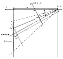
視差変換パラメータの算出手法について説明する。図3は、傾き角αで対象物Oを撮像する一対のカメラの状態を示す説明図である。図4は、傾き角αで撮像される画像データおよび距離データの説明図であって、(a)は、傾き角αで対象物Oを撮影したときの画像データを示す図であり、(b)は、距離データにおける注目点Goを含むio座標上の視差を示す図である。また、図5は、視差変換パラメータの算出手法の説明図である。
【0030】
図3において、画像平面上の注目点Go(図4参照)に対応する対象物O上の点(実空間における点)が、点Oo(xo,yo,zo)で示されている。また、図5において、傾き角αで取り付けられたカメラ2a,2bの画角が、破線によって示されている。画像データと対象物Oとの対応付けを明確にするため、このカメラ2a,2bによって撮像される像を反映するスクリーンが、同図に示されている。なお、図中に示した実空間を表すxyz軸の座標系は、一対のカメラ2a,2bの取付位置を基準として、カメラ2a,2bの距離方向をz軸、地面からの高さ方向をy軸、y軸と直交する平面内でのz軸との直交方向をx軸と定義している。
【0031】
傾き角α(本実施形態では、水平面に関して下側にα傾く)で、垂直に起立する矩形の壁面(対象物O)を撮影した場合、対象物Oは、実際の形状より下側が窄んだ台形形状に写し出される(図4(a)参照)。画像を実空間に対応させた場合、この対象物Oの歪みによって、対象物Oのx方向の位置にずれが生じる。これら画像データに基づき算出される距離データに関しても同様であり、対象物Oに関する視差の位置もx方向(正確には、i方向)にずれる。
【0032】
さらに、傾き角αで対象物Oを撮影した場合、カメラ視線上における距離の遠近により、算出される視差の値自体にもずれが生じる(図4(b)参照)。このようなずれは、距離データを実空間に対応させた場合、z方向へのずれとなって現れる。よって、図4に示すような画像データおよび距離データを用いて、周知の変換式より算出される対象物Oの位置は、実際の対象物Oの実空間上の位置と完全に一致しない。
【0033】
一般に、ステレオカメラが傾いていない状態では、注目点Goにおける視差は、ステレオカメラと対象物との距離、すなわち、図5に示すように、光学中心線上での距離Loに対応した値となる。しかしながら、ステレオカメラ2に傾き角αがある場合、ステレオカメラ2と対象物Oとの光学中心線上での距離(すなわち、視差の値に対応する距離)は、傾き角αにともないLoよりも長いLo+ΔLoとなる。したがって、傾き角αで撮影された距離データから特定される視差の値は、傾き角αと画像上の注目点Goとに起因して変化するΔLoの値を考慮する必要がある。
【0034】
ステレオカメラ2から対象物Oまでの相対距離(z方向距離)が同一である場合、対象物Oに関する全ての視差は、一様な値であることが好ましい。先に述べた光学中心線上での距離に拘わらず、カメラと対象物との相対的な距離(zo)によって、視差が特定されるのであれば、周知のステレオ画像処理を用いて実空間への変換処理を行うことができる。したがって、上述したLo+ΔLoとzoとを対応付けることで、距離データを構成する視差dから、zoに起因した視差dhを一義的に特定することができる。ここで、実空間における注目点Ooと光軸との間の距離をl、CCDの縦方向におけるピクセルサイズをpsv、焦点距離をfとした場合、ΔLoは、以下に示す数式3で示される。
【数3】
また、lは、以下に示す数式4で示される。
【数4】
数式3に数式4を代入し整理すると、数式3は、以下に示す数式5に書き換えられる。
【数5】
ΔLo=Lo・PWV2・(jv−jc)・(jo−jc)
【0037】
ここで、PWVは、上述したように一画素当たり垂直視野角であり、PWV=psv/fの関係を有する。
【0038】
一方、数式6に示す関係式から、zoは、数式7で示すことができる。
【数6】
そして、zoとdh、および、Loとdとはそれぞれ対応する値であるので、数式7に示すzoおよびLoを、dhおよびdで適宜置き換えることにより、数式2に示す視差変換パラメータを得ることができる。
【0040】
つぎに、ステップ5において、位置補正部10は、画像データと補正された距離データとについて、傾き角αにより特定される位置変換パラメータに基づいて、画像上の座標位置を幾何学的に補正する。この位置変換パラメータは、以下に示す数式8により表され、画像上の(io,jo)座標における注目点Go、この数式8によって一義的に座標(ih,jo)に補正(変換)される。
【数8】
図6は、距離データおよび画像データの歪みを補正する変換パラメータの算出手法を示す説明図である。上述したように、画像には位置的なずれが生じており、視差を補正したとしても、この位置的なずれは、依然として存在する(実空間での、x方向のずれ)。したがって、実空間でのx座標の値と、画像から特定されるx座標との位置が変わらないように、画像上のio座標の位置を補正する必要がある。注目点Goと対応する対象物O上の点Ooとにより、xoは、以下に示す数式9の関係式を満たす。
【数9】
ここで、icは画像データおよび距離データにおける光学中心線のi座標、pshは画像の一画素当たりの横方向のピクセルサイズ(画素幅)である。
【0043】
一方、ioが補正される画像上のi座標をihとすると、これに対応する実空間上のzoとの関係より、xoは、数式10の関係を更に満たす。
【数10】
よって、この数式9と数式10とでxoが共通するihとioとの関係を導き、そして、先にもとめた数式7を代入することで、数式8を得ることができる。
【0045】
そして、ステップ6において、位置補正部10は、補正された視差dhおよび輝度値を、補正されたあらたな座標(ih,jo)に格納する。そして、ステップ7,8、および、ステップ9,10に従い、視差補正部9および位置補正部10は、このような補正処理を距離データおよび画像データの全てのi−j座標について行う。ここで、図7は、本実施形態にかかる補正処理を行った画像データおよび距離データの説明図である。図7の(a),(b)は、図3に示した(a),(b)にそれぞれ対応する。
【0046】
全てのi−j座標において補正処理が行われると、ステップ11において、補間部11は、視差の欠落が生じた座標位置に関する視差を周囲の視差に基づいて補間する内挿処理を行う。一般的に、ステップ5,6で示した座標変換を行った場合、変換後の画素データは、メッシュ状に整列しない。すなわち、変換後の画像データおよび距離データにおける座標の一部には、データの欠落箇所が存在する場合がある。そこで、補間部11は、画像平面において、データが欠落している座標位置を特定するとともに、特定された座標について、その周辺の座標における輝度値または視差に基づき、統計的な補間処理を行う。
【0047】
以上のような処理によって、画像データおよび距離データの補正を行うことにより、傾き角αがある場合であっても、カメラの光学的性質にともなう画像の歪みおよび視差のずれは補正される。これにより、画像データおよび距離データから特定される三次元空間が、実際の実空間と位置的なずれを生じることがない。そして、この手法により算出された距離データおよび元画像を用いれば、各種の監視制御において、高精度な監視制御を行うことが可能となる。
【0048】
なお、上述した実施形態では、視差補正部9および位置補正部10は、変換パラメータ(数式2および数式8)を用いて、毎回(i−j成分毎に)計算処理を行うものである。しかしながら、計算処理を効率よく行うためにも、視差補正部9は、変換パラメータのうち一部を予め計算し、この計算結果を保持するテーブルを格納してもよい。換言すれば、視差補正部9は、傾き角αと、この傾き角αと(さらには、画像上の位置とに)対応する変換パラメータが定義された対応表を格納する記憶部を更に有することが好ましい。この場合、視差補正部9は、検出された傾き角αの値からこの対応表によって特定される補正係数に基づいて、距離データの視差の値dを視差dhに補正することができる。
【0049】
図8は、対応表の一例を示す図である。このよう対応表は、傾き角α(数式2におけるjvであ、例えば、α=-30〜60度に対応するjvとして、例示的に-30〜360)と、注目点jo(例示的に0〜199)とに対応させて予め作成することができる。この対応表によって特定される変換パラメータを、table(jv,jo)とするならば、数式2および数式8は、それぞれ、数式11および数式12に代替される。
【数11】
dh=table(jv,jc)×d
【数12】
ih=ic+table(jv,jc)×(io−ic)
【0050】
なお、数式12から理解されるように、視差補正部9で使用される対応表は、位置補正部10の補正処理においても共通して使用可能な対応表である。したがって、位置補正部10が、同様の対応表を格納する構成であってもよいが、視差補正部9がこの補正係数を位置補正部10に出力するような構成であってもよい。
【0051】
また、角度検出部7は、ステレオカメラ2の傾き角αを実際に検出するものであるが、この傾き角αを画像データから検出することができる。具体的には、角度検出部7は、画像データのうち少なくとも一方の画像(例えば、基準画像データ)を解析することで消失点を検出し、消失点の位置に基づいて、傾き角αを検出する。
【0052】
以上説明したように、本発明の画像補正装置は、ステレオ式監視システム1の一部として機能するばかりではなく、上述した画像補正を目的とした装置単体としても機能することができることはいうまでもない。
【0053】
【発明の効果】
このように、本発明にかかる画像補正装置および方法によれば、距離データを補正することで、傾き角に伴う画像上のずれを補正することができる。これにより、かかる画像から特定される三次元空間は、実空間と距離的なずれを生じさせないので、監視システムの信頼度を向上することができる。
【図面の簡単な説明】
【図1】本実施形態にかかるステレオ式監視システムのブロック図
【図2】本実施例にかかる画像の補正処理の手順を示したフローチャート
【図3】傾き角αで対象物Oを撮像する一対のカメラの状態を示す説明図
【図4】傾き角αで撮像される画像データおよび距離データの説明図
【図5】視差変換パラメータの算出手法の説明図
【図6】画像の歪みを補正する変換パラメータの算出手法を示す説明図
【図7】本実施形態にかかる補正処理を行った画像データおよび距離データの説明図
【図8】対応表の一例を示す図
【符号の説明】
1 ステレオ式監視システム
2 ステレオカメラ
2a メインカメラ
2b サブカメラ
3 A/Dコンバータ
4 A/Dコンバータ
5 画像補正部
6 ステレオ画像処理部
7 角度検出部
8 補正処理部
9 視差補正部
10 位置補正部
11 補間部
12 画像データメモリ
13 距離データメモリ
14 認識部[0001]
BACKGROUND OF THE INVENTION
The present invention relates to an image correction apparatus and an image correction method for a stereo camera with a depression angle.
[0002]
[Prior art]
In recent years, a monitoring system using a stereo camera has been noticed and put into practical use. In this type of monitoring system, a positional shift amount (that is, parallax) related to the same object projected in a pair of captured images is calculated using stereo matching. The position of the object projected on the image in the real space can be calculated by a known coordinate conversion formula based on the parallax calculated with respect to the object and the position on the image plane.
[0003]
In general, when a vertical wall surface (horizontal rectangle) is imaged using a camera having a predetermined tilt angle (degree of vertical tilt with respect to a horizontal plane), the wall surface is projected in a distorted shape. This is because of the optical properties of the camera, and even when a wall surface having the same width is photographed, the portion closer to the camera appears larger. Therefore, a method for eliminating such optical properties and obtaining a natural captured image has been proposed as “tilting correction” in Japanese Patent Laid-Open No. 5-91409, for example.
[0004]
In a conventional surveillance system, a stereo camera is generally used in a state where there is almost no inclination (angle of depression = 0), and in this case, the above-described image distortion is slight. For this reason, normally, the processing is executed with the distortion of the image ignored, that is, the inclination angle (the depression angle) = 0. When a vertically standing wall surface is photographed using a stereo camera in such a state, the parallax value calculated for the wall surface is uniform. As a result, the distance from the stereo camera to the wall surface in the real space is also uniform.
[0005]
[Problems to be solved by the invention]
By the way, from the viewpoint of giving a degree of freedom to the camera arrangement, it is not preferable to limit the tilt angle of the stereo camera to 0 degrees. However, when the above-described wall surface is photographed by the stereo camera with a depression angle, the parallax regarding the wall surface differs for each wall surface part. As a result, the distance from the stereo camera to the wall surface in real space is not uniform. Therefore, in the conventional processing method, when a stereo camera with a depression angle is used, it is difficult to accurately recognize an object.
[0006]
By applying the above-mentioned “tilting correction” to the stereo image processing, it is conceivable to solve the disadvantage associated with the tilt angle. In this case, the image on the image sensor can be corrected two-dimensionally. However, even if this technique is applied to stereo image processing that handles an image having three-dimensional information (that is, parallax), the image is completely displayed. Cannot be corrected.
[0007]
The present invention has been made in view of such circumstances, and an object thereof is to correct a positional deviation between the three-dimensional space specified by the stereo image processing and the real space.
[0008]
[Means for Solving the Problems]
In order to solve such a problem, the first invention provides an image correction apparatus for a stereo camera with a depression angle. The stereo camera is attached in a state where the visual axis of the camera is inclined with respect to the horizontal plane, and outputs a pair of image data. The stereo image processing unit calculates parallax by stereo matching based on a pair of image data, and outputs distance data in which a parallax group related to image data corresponding to one frame is associated with a coordinate position on the image plane. The angle detection unit detects an inclination angle formed by the horizontal plane and the visual axis of the camera. The parallax correction unit calculates a parallax conversion parameter for each coordinate position based on the tilt angle detected by the angle detection unit,For each calculated coordinate positionBased on the parallax conversion parameters, individual parallax values constituting the distance data are corrected.
[0009]
Here, in the first invention, a position conversion parameter for each coordinate position is calculated based on the inclination angle detected by the angle detection unit, and the coordinate position of the distance data is calculated based on the calculated position conversion parameter. You may further provide the position correction | amendment part which correct | amends scientifically. In this case, it is preferable to further provide an interpolating unit that interpolates the parallax at the coordinate position where the missing portion is generated based on the surrounding parallax when the missing portion occurs at a certain coordinate position due to the correction by the position correcting unit.
[0010]
In the first invention, it is preferable that the position correction unit geometrically corrects the coordinate position of the image data based on the position conversion parameter.
[0011]
In the first invention, the angle detection unit may detect a vanishing point by analyzing image data, and may detect an inclination angle based on the position of the vanishing point.
[0012]
The second invention provides an image correction method for a stereo camera with a depression angle. Such a correction method includes the following steps. In the first step, a pair of image data is obtained by capturing a scene with a stereo camera attached with the visual axis of the camera tilted with respect to a horizontal plane. In the second step, parallax is calculated by stereo matching based on a pair of image data, and distance data in which a parallax group obtained from image data corresponding to one frame is associated with a coordinate position on the image plane is obtained. Output. In the third step, an inclination angle formed by the horizontal plane and the visual axis of the camera is detected. In the fourth step, a parallax conversion parameter for each coordinate position is calculated based on the detected inclination angle. The fifth step isFor each calculated coordinate positionBased on the parallax conversion parameters, individual parallax values constituting the distance data are corrected.In addition, the third invention is attached in a state where the visual axis of the camera is inclined with respect to the horizontal plane, and the stereo camera that outputs a pair of image data and the parallax by stereo matching based on the pair of image data. A stereo image processing unit that calculates and outputs distance data in which disparity groups in the image data are associated with coordinate positions on the image plane; and an angle detection unit that detects an inclination angle formed between the horizontal plane and the visual axis of the camera; The parallax conversion parameter for each coordinate position is calculated based on the inclination angle detected by the angle detection unit, and the parallax value constituting the distance data is corrected based on the calculated parallax conversion parameter for each coordinate position. An image correction apparatus having a parallax correction unit is provided.
[0013]
Here, in the second invention, a sixth step of calculating a position conversion parameter for each coordinate position based on the detected inclination angle, and a coordinate position of the distance data based on the calculated position conversion parameter. A seventh step of geometric correction may be further provided. In this case, when a loss of parallax occurs at a certain coordinate position due to the correction of the coordinate position of the distance data, an eighth step of interpolating the parallax at the coordinate position where the loss occurs based on surrounding parallax may be further provided. preferable.
[0014]
DETAILED DESCRIPTION OF THE INVENTION
FIG. 1 is a block diagram of a stereo monitoring system according to the present embodiment. The
[0015]
The
[0016]
Through such image processing, reference image data is obtained from the main camera 2a, and comparison image data is obtained from the sub camera 2b. These image data are a set of luminance values (0 to 255) of each pixel included in the individually set effective image area. In the ij coordinate system on the image plane, the lower left corner of the image is the origin, the horizontal direction is the i coordinate axis, and the vertical direction is the j coordinate axis. Both image data corresponding to one frame, which is the minimum display unit of one image, are output to the subsequent stereo
[0017]
The stereo
[0018]
When calculating the parallax d regarding a certain pixel block PBij (correlation source), a region (correlation destination) having a correlation with the luminance characteristic of the pixel block PBij is specified in the comparison image. As described above, the distance from the cameras 2a and 2b to the object appears as a horizontal shift amount between the reference image and the comparison image. Therefore, when searching for the correlation destination in the comparison image, it is only necessary to search on the same horizontal line (epipolar line) as the j coordinate of the pixel block Pij as the correlation source. The stereo
[0019]
The correlation between two pixel blocks can be evaluated, for example, by calculating a city block distance CB.
[Expression 1]
CB = Σ | p1ij−p2ij |
[0020]
Basically, among the city block distances CB calculated for each pixel block existing on the epipolar line, the pixel block having the smallest value is determined as the correlation destination. The amount of deviation between the correlation destination specified in this way and the correlation source is the parallax d. Note that the hardware configuration of the stereo
[0021]
The
[0022]
The
[0023]
The parallax correction unit 9 acquires the inclination angle α detected by the
[0024]
The recognition unit 14 recognizes the three-dimensional position of the object based on the distance data stored in the distance data memory 13. In addition, the recognition unit 14 uses image data stored in the image data memory 12 as appropriate when recognizing an object. The object to be recognized is appropriately set according to the purpose of use of the monitoring device. For example, in an out-of-vehicle monitoring system that monitors the traveling state ahead of the host vehicle, a lane, a preceding vehicle, or the like is an object to be recognized. In a level crossing monitoring system, it becomes an object to be recognized by railroad rails, passing cars, passersby, and the like. In the altitude monitoring system of the flying object and the system for detecting the undulation state of the ground surface, the ground is an object to be recognized.
[0025]
FIG. 2 is a flowchart showing a procedure of image correction processing according to the present embodiment. First, in
[0026]
In
[0027]
Regarding this correction processing, first, in step 4, the parallax correction unit 9 corrects the parallax value d in the distance data based on the parallax conversion parameter specified by the inclination angle α. This parallax conversion parameter is expressed by the following
[Expression 2]
In
[0029]
A method for calculating the parallax conversion parameter will be described. FIG. 3 is an explanatory diagram illustrating a state of a pair of cameras that capture an image of the object O at an inclination angle α. FIG. 4 is an explanatory diagram of image data and distance data imaged at an inclination angle α, and FIG. 4A is a diagram showing image data when the object O is imaged at an inclination angle α. ) Is a diagram showing the parallax on the io coordinate including the attention point Go in the distance data. FIG. 5 is an explanatory diagram of a parallax conversion parameter calculation method.
[0030]
In FIG. 3, a point on the object O (a point in the real space) corresponding to the attention point Go (see FIG. 4) on the image plane is indicated by a point Oo (xo, yo, zo). Further, in FIG. 5, the angles of view of the cameras 2a and 2b attached at the inclination angle α are indicated by broken lines. In order to clarify the association between the image data and the object O, a screen reflecting images captured by the cameras 2a and 2b is shown in FIG. The xyz-axis coordinate system representing the real space shown in the figure is based on the mounting position of the pair of cameras 2a and 2b as a reference, the distance direction of the cameras 2a and 2b is the z-axis, and the height direction from the ground is y. A direction orthogonal to the z-axis in a plane orthogonal to the axis and the y-axis is defined as the x-axis.
[0031]
When a rectangular wall surface (object O) standing upright at an inclination angle α (in this embodiment, α is inclined downward with respect to the horizontal plane), the object O is narrowed below the actual shape. It is projected into a trapezoidal shape (see FIG. 4A). When the image corresponds to the real space, the distortion of the object O causes a shift in the position of the object O in the x direction. The same applies to the distance data calculated based on these image data, and the position of the parallax regarding the object O is also shifted in the x direction (more accurately, the i direction).
[0032]
Furthermore, when the object O is photographed at an inclination angle α, the calculated parallax value itself is also shifted depending on the distance on the camera line of sight (see FIG. 4B). Such a shift appears as a shift in the z direction when distance data is associated with real space. Therefore, the position of the object O calculated by a well-known conversion equation using image data and distance data as shown in FIG. 4 does not completely coincide with the position of the actual object O in the real space.
[0033]
In general, when the stereo camera is not tilted, the parallax at the attention point Go is a value corresponding to the distance between the stereo camera and the object, that is, the distance Lo on the optical center line as shown in FIG. However, when the
[0034]
When the relative distance (z-direction distance) from the
[Equation 3]
Moreover, l is shown by the following numerical formula 4.
[Expression 4]
Substituting Equation 4 into
[Equation 5]
ΔLo = Lo · PWV2(Jv-jc) (jo-jc)
[0037]
Here, PWV is a vertical viewing angle per pixel as described above, and has a relationship of PWV = psv / f.
[0038]
On the other hand, from the relational expression shown in
[Formula 6]
Since zo and dh and Lo and d are respectively corresponding values, disparity conversion parameters shown in
[0040]
Next, in
[Equation 8]
FIG. 6 is an explanatory diagram illustrating a conversion parameter calculation method for correcting distortion of distance data and image data. As described above, there is a positional shift in the image, and even if the parallax is corrected, this positional shift still exists (shift in the x direction in real space). Therefore, it is necessary to correct the position of the io coordinate on the image so that the position of the x coordinate value in the real space and the position of the x coordinate specified from the image do not change. With the attention point Go and the corresponding point Oo on the object O, xo satisfies the following relational expression (9).
[Equation 9]
Here, ic is the i coordinate of the optical center line in the image data and distance data, and psh is the horizontal pixel size (pixel width) per pixel of the image.
[0043]
On the other hand, if the i coordinate on the image in which io is corrected is ih, xo further satisfies the relationship of
[Expression 10]
Therefore,
[0045]
In
[0046]
When correction processing has been performed for all ij coordinates, in step 11, the interpolation unit 11 performs interpolation processing for interpolating the parallax regarding the coordinate position where the loss of parallax has occurred based on the surrounding parallax. Generally, when the coordinate conversion shown in
[0047]
By correcting the image data and the distance data by the processing as described above, even if there is an inclination angle α, image distortion and parallax shift due to the optical properties of the camera are corrected. Thereby, the three-dimensional space specified from the image data and the distance data does not cause a positional deviation from the actual real space. If the distance data and the original image calculated by this method are used, high-precision monitoring control can be performed in various types of monitoring control.
[0048]
In the above-described embodiment, the parallax correction unit 9 and the
[0049]
FIG. 8 is a diagram illustrating an example of the correspondence table. In this way, the correspondence table includes the inclination angle α (jv in
[Expression 11]
dh = table (jv, jc) × d
[Expression 12]
ih = ic + table (jv, jc) × (io−ic)
[0050]
As can be understood from Equation 12, the correspondence table used in the parallax correction unit 9 is a correspondence table that can be used in common in the correction processing of the
[0051]
The
[0052]
As described above, it goes without saying that the image correction apparatus of the present invention can function not only as a part of the
[0053]
【The invention's effect】
As described above, according to the image correction apparatus and method of the present invention, it is possible to correct a shift on an image due to an inclination angle by correcting distance data. As a result, the three-dimensional space specified from the image does not cause a distance shift from the real space, so that the reliability of the monitoring system can be improved.
[Brief description of the drawings]
FIG. 1 is a block diagram of a stereo monitoring system according to an embodiment.
FIG. 2 is a flowchart showing a procedure of image correction processing according to the embodiment.
FIG. 3 is an explanatory diagram showing a state of a pair of cameras that capture an image of an object O at an inclination angle α
FIG. 4 is an explanatory diagram of image data and distance data captured at an inclination angle α.
FIG. 5 is an explanatory diagram of a parallax conversion parameter calculation method.
FIG. 6 is an explanatory diagram illustrating a conversion parameter calculation method for correcting image distortion;
FIG. 7 is an explanatory diagram of image data and distance data subjected to correction processing according to the embodiment.
FIG. 8 is a diagram showing an example of a correspondence table
[Explanation of symbols]
1 Stereo monitoring system
2 Stereo camera
2a Main camera
2b Sub camera
3 A / D converter
4 A / D converter
5 Image correction unit
6 Stereo image processing unit
7 Angle detector
8 Correction processing section
9 Parallax correction unit
10 Position correction unit
11 Interpolator
12 Image data memory
13 Distance data memory
14 Recognition part
Claims (9)
水平面に対してカメラの視軸が傾いた状態で取り付けられており、一対の画像データを出力するステレオカメラと、
前記一対の画像データに基づいて、ステレオマッチングにより視差を算出し、画像データに関する視差群と画像平面上の座標位置とが対応付けられた距離データを出力するステレオ画像処理部と、
前記水平面と前記カメラの視軸とがなす傾き角を検出する角度検出部と、
前記角度検出部によって検出された前記傾き角に基づいて、前記座標位置毎の視差変換パラメータを算出し、当該算出された座標位置毎の視差変換パラメータに基づいて、前記距離データを構成する個々の視差の値を補正する視差補正部と
を有することを特徴とする画像補正装置。In the image correction device,
A stereo camera that is attached with the visual axis of the camera tilted with respect to the horizontal plane, and outputs a pair of image data;
A stereo image processing unit that calculates parallax by stereo matching based on the pair of image data and outputs distance data in which a parallax group related to the image data and a coordinate position on the image plane are associated;
An angle detection unit for detecting an inclination angle formed by the horizontal plane and the visual axis of the camera;
Based on the tilt angle detected by the angle detection unit, a parallax conversion parameter for each coordinate position is calculated, and the distance data is configured based on the calculated parallax conversion parameter for each coordinate position . An image correction apparatus comprising: a parallax correction unit that corrects a parallax value.
水平面に対してカメラの視軸が傾いた状態で取り付けられたステレオカメラで景色を撮像することにより、一対の画像データを得る第1のステップと、
前記一対の画像データに基づいて、ステレオマッチングにより視差を算出し、一フレーム相当の画像データより得られた視差群と画像平面上の座標位置とが対応付けられた距離データを出力する第2のステップと、
前記水平面と前記カメラの視軸とがなす傾き角を検出する第3のステップと、
前記検出された傾き角に基づいて、前記座標位置毎の視差変換パラメータを算出する第4のステップと、
前記算出された座標位置毎の視差変換パラメータに基づいて、前記距離データを構成する個々の視差の値を補正する第5のステップと
を有することを特徴とする画像補正方法。In the image correction method,
A first step of obtaining a pair of image data by capturing a scene with a stereo camera attached with the camera's visual axis tilted with respect to a horizontal plane;
A second parallax is calculated by stereo matching based on the pair of image data, and distance data in which a parallax group obtained from image data corresponding to one frame is associated with a coordinate position on an image plane is output. Steps,
A third step of detecting an inclination angle formed by the horizontal plane and the visual axis of the camera;
A fourth step of calculating a parallax conversion parameter for each coordinate position based on the detected inclination angle;
An image correction method comprising: a fifth step of correcting individual parallax values constituting the distance data based on the calculated parallax conversion parameter for each coordinate position .
前記算出された位置変換パラメータに基づいて、前記距離データの座標位置を幾何学的に補正する第7のステップとをさらに有することを特徴とする請求項6に記載された画像補正方法。A sixth step of calculating a position conversion parameter for each coordinate position based on the detected inclination angle;
The image correction method according to claim 6, further comprising a seventh step of geometrically correcting the coordinate position of the distance data based on the calculated position conversion parameter.
水平面に対してカメラの視軸が傾いた状態で取り付けられており、一対の画像データを出力するステレオカメラと、
前記一対の画像データに基づいて、ステレオマッチングにより視差を算出し、画像データにおける視差群と画像平面上の座標位置とが対応付けられた距離データを出力するステレオ画像処理部と、
前記水平面と前記カメラの視軸とがなす傾き角を検出する角度検出部と、
前記角度検出部によって検出された前記傾き角に基づいて、前記座標位置毎の視差変換パラメータを算出し、当該算出された座標位置毎の視差変換パラメータに基づいて、前記距離データを構成する視差の値を補正する視差補正部と
を有することを特徴とする画像補正装置。In the image correction device,
A stereo camera that is attached with the visual axis of the camera tilted with respect to the horizontal plane, and outputs a pair of image data;
A stereo image processing unit that calculates parallax by stereo matching based on the pair of image data and outputs distance data in which a parallax group in the image data and a coordinate position on the image plane are associated;
An angle detection unit for detecting an inclination angle formed by the horizontal plane and the visual axis of the camera;
Based on the tilt angle detected by the angle detection unit, a parallax conversion parameter for each coordinate position is calculated, and based on the calculated parallax conversion parameter for each coordinate position, the disparity of the disparity constituting the distance data is calculated. An image correction apparatus comprising: a parallax correction unit that corrects a value.
Priority Applications (1)
| Application Number | Priority Date | Filing Date | Title |
|---|---|---|---|
| JP2002110245A JP4172684B2 (en) | 2002-04-12 | 2002-04-12 | Image correction apparatus and image correction method |
Applications Claiming Priority (1)
| Application Number | Priority Date | Filing Date | Title |
|---|---|---|---|
| JP2002110245A JP4172684B2 (en) | 2002-04-12 | 2002-04-12 | Image correction apparatus and image correction method |
Publications (3)
| Publication Number | Publication Date |
|---|---|
| JP2003303337A JP2003303337A (en) | 2003-10-24 |
| JP2003303337A5 JP2003303337A5 (en) | 2005-09-22 |
| JP4172684B2 true JP4172684B2 (en) | 2008-10-29 |
Family
ID=29393451
Family Applications (1)
| Application Number | Title | Priority Date | Filing Date |
|---|---|---|---|
| JP2002110245A Expired - Fee Related JP4172684B2 (en) | 2002-04-12 | 2002-04-12 | Image correction apparatus and image correction method |
Country Status (1)
| Country | Link |
|---|---|
| JP (1) | JP4172684B2 (en) |
Families Citing this family (11)
| Publication number | Priority date | Publication date | Assignee | Title |
|---|---|---|---|---|
| JP4839827B2 (en) * | 2005-12-26 | 2011-12-21 | コニカミノルタセンシング株式会社 | 3D measuring device |
| JP5481337B2 (en) | 2010-09-24 | 2014-04-23 | 株式会社東芝 | Image processing device |
| KR101317839B1 (en) | 2011-12-19 | 2013-10-15 | 경북대학교 산학협력단 | An image object detection apparatus and method of the same |
| JP6044868B2 (en) * | 2012-06-26 | 2016-12-14 | 株式会社リコー | Stereo camera calibration apparatus and method, and distance measurement apparatus |
| JP6202356B2 (en) * | 2012-07-02 | 2017-09-27 | 株式会社リコー | Image processing apparatus and method, and imaging apparatus |
| EP2757524B1 (en) * | 2013-01-16 | 2018-12-19 | Honda Research Institute Europe GmbH | Depth sensing method and system for autonomous vehicles |
| JP5634558B2 (en) * | 2013-04-30 | 2014-12-03 | 株式会社東芝 | Image processing device |
| JP6950170B2 (en) * | 2016-11-30 | 2021-10-13 | 株式会社リコー | Information processing device, imaging device, device control system, information processing method, and program |
| JP6872239B2 (en) * | 2017-07-28 | 2021-05-19 | 国立大学法人電気通信大学 | Image processing equipment, image processing method and image processing program |
| JP6865660B2 (en) * | 2017-09-11 | 2021-04-28 | Kyb株式会社 | Distance calculation device and distance calculation parameter setting method |
| JP2020106275A (en) * | 2018-12-26 | 2020-07-09 | Whill株式会社 | Stereo camera and electric mobility |
-
2002
- 2002-04-12 JP JP2002110245A patent/JP4172684B2/en not_active Expired - Fee Related
Also Published As
| Publication number | Publication date |
|---|---|
| JP2003303337A (en) | 2003-10-24 |
Similar Documents
| Publication | Publication Date | Title |
|---|---|---|
| JP4172554B2 (en) | Stereo camera adjustment device | |
| JP5792662B2 (en) | Parallax calculation device, distance calculation device, and parallax calculation method | |
| JP4889351B2 (en) | Image processing apparatus and processing method thereof | |
| JP5362189B2 (en) | Image processing apparatus and processing method thereof | |
| JP3539788B2 (en) | Image matching method | |
| JP3054681B2 (en) | Image processing method | |
| JP4243767B2 (en) | Fisheye lens camera device and image extraction method thereof | |
| JPH1093808A (en) | Image synthesis device/method | |
| JP2004354257A (en) | Calibration slippage correction device, and stereo camera and stereo camera system equipped with the device | |
| WO2018235163A1 (en) | Calibration device, calibration chart, chart pattern generation device, and calibration method | |
| JP4172684B2 (en) | Image correction apparatus and image correction method | |
| JP2009517683A (en) | A method for obtaining scattered parallax field in stereo vision | |
| JP4032843B2 (en) | Monitoring system and monitoring method, distance correction device and distance correction method in the monitoring system | |
| JP3958638B2 (en) | Stereo image processing apparatus and stereo image processing method | |
| TW201225658A (en) | Imaging device, image-processing device, image-processing method, and image-processing program | |
| JP2020182045A (en) | Panorama video composition device, panorama video composition method, and panorama video composition program | |
| JP2003304561A (en) | Stereo image processing apparatus | |
| JP2004186922A (en) | Wide range photographing method using a plurality of cameras | |
| JPH05303629A (en) | Method for synthesizing shape | |
| JP3008875B2 (en) | Subject extraction device | |
| JP4394487B2 (en) | Stereo image processing device | |
| JPH11325890A (en) | Picture correcting apparatus for stereoscopic camera | |
| JP4209637B2 (en) | Distance correction apparatus and distance correction method for monitoring system | |
| JP2007322404A (en) | Image processing device and its processing method | |
| JP4150218B2 (en) | Terrain recognition device and terrain recognition method |
Legal Events
| Date | Code | Title | Description |
|---|---|---|---|
| A521 | Request for written amendment filed |
Free format text: JAPANESE INTERMEDIATE CODE: A523 Effective date: 20050407 |
|
| A621 | Written request for application examination |
Free format text: JAPANESE INTERMEDIATE CODE: A621 Effective date: 20050407 |
|
| A977 | Report on retrieval |
Free format text: JAPANESE INTERMEDIATE CODE: A971007 Effective date: 20080423 |
|
| A131 | Notification of reasons for refusal |
Free format text: JAPANESE INTERMEDIATE CODE: A131 Effective date: 20080515 |
|
| A521 | Request for written amendment filed |
Free format text: JAPANESE INTERMEDIATE CODE: A523 Effective date: 20080711 |
|
| TRDD | Decision of grant or rejection written | ||
| A01 | Written decision to grant a patent or to grant a registration (utility model) |
Free format text: JAPANESE INTERMEDIATE CODE: A01 Effective date: 20080808 |
|
| A01 | Written decision to grant a patent or to grant a registration (utility model) |
Free format text: JAPANESE INTERMEDIATE CODE: A01 |
|
| A61 | First payment of annual fees (during grant procedure) |
Free format text: JAPANESE INTERMEDIATE CODE: A61 Effective date: 20080808 |
|
| R150 | Certificate of patent or registration of utility model |
Free format text: JAPANESE INTERMEDIATE CODE: R150 Ref document number: 4172684 Country of ref document: JP Free format text: JAPANESE INTERMEDIATE CODE: R150 |
|
| FPAY | Renewal fee payment (event date is renewal date of database) |
Free format text: PAYMENT UNTIL: 20110822 Year of fee payment: 3 |
|
| FPAY | Renewal fee payment (event date is renewal date of database) |
Free format text: PAYMENT UNTIL: 20110822 Year of fee payment: 3 |
|
| FPAY | Renewal fee payment (event date is renewal date of database) |
Free format text: PAYMENT UNTIL: 20120822 Year of fee payment: 4 |
|
| R250 | Receipt of annual fees |
Free format text: JAPANESE INTERMEDIATE CODE: R250 |
|
| FPAY | Renewal fee payment (event date is renewal date of database) |
Free format text: PAYMENT UNTIL: 20120822 Year of fee payment: 4 |
|
| FPAY | Renewal fee payment (event date is renewal date of database) |
Free format text: PAYMENT UNTIL: 20130822 Year of fee payment: 5 |
|
| R250 | Receipt of annual fees |
Free format text: JAPANESE INTERMEDIATE CODE: R250 |
|
| R250 | Receipt of annual fees |
Free format text: JAPANESE INTERMEDIATE CODE: R250 |
|
| R250 | Receipt of annual fees |
Free format text: JAPANESE INTERMEDIATE CODE: R250 |
|
| S531 | Written request for registration of change of domicile |
Free format text: JAPANESE INTERMEDIATE CODE: R313531 |
|
| R350 | Written notification of registration of transfer |
Free format text: JAPANESE INTERMEDIATE CODE: R350 |
|
| R250 | Receipt of annual fees |
Free format text: JAPANESE INTERMEDIATE CODE: R250 |
|
| R250 | Receipt of annual fees |
Free format text: JAPANESE INTERMEDIATE CODE: R250 |
|
| S533 | Written request for registration of change of name |
Free format text: JAPANESE INTERMEDIATE CODE: R313533 |
|
| R350 | Written notification of registration of transfer |
Free format text: JAPANESE INTERMEDIATE CODE: R350 |
|
| R250 | Receipt of annual fees |
Free format text: JAPANESE INTERMEDIATE CODE: R250 |
|
| R250 | Receipt of annual fees |
Free format text: JAPANESE INTERMEDIATE CODE: R250 |
|
| R250 | Receipt of annual fees |
Free format text: JAPANESE INTERMEDIATE CODE: R250 |
|
| LAPS | Cancellation because of no payment of annual fees |