JP4172592B2 - Disc loading roll - Google Patents
Disc loading roll Download PDFInfo
- Publication number
- JP4172592B2 JP4172592B2 JP2005036850A JP2005036850A JP4172592B2 JP 4172592 B2 JP4172592 B2 JP 4172592B2 JP 2005036850 A JP2005036850 A JP 2005036850A JP 2005036850 A JP2005036850 A JP 2005036850A JP 4172592 B2 JP4172592 B2 JP 4172592B2
- Authority
- JP
- Japan
- Prior art keywords
- disk
- loading roll
- roll
- less
- loading
- Prior art date
- Legal status (The legal status is an assumption and is not a legal conclusion. Google has not performed a legal analysis and makes no representation as to the accuracy of the status listed.)
- Expired - Fee Related
Links
Images


Landscapes
- Feeding And Guiding Record Carriers (AREA)
Description
本発明は、音響機器、情報機器、映像機器等で使用されるCD、LD、DVD等の光ディスクまたは光磁気ディスク等のディスクを各機器内に搬送するためのディスクローディングロールに関し、ディスクに付着した埃、特に砂埃等でスリップしてローディング、イジェクトができないことがないように工夫したものである。 The present invention relates to a disc loading roll for transporting a disc such as an optical disc such as a CD, LD, DVD or magneto-optical disc used in audio equipment, information equipment, video equipment, etc. into each equipment, and is attached to the disc. It is designed to prevent loading and ejecting by slipping with dust, especially sand dust.
従来より、CD、LD、DVD等の光ディスクまたは光磁気ディスク等を装置内のターンテーブルにセットするために、相対向する一対のローディングロールが使用されている。例えば、図5に示すように、ローディングロール1の中心には軸2が貫通状態で設けられており、相対向して同様のローディングロールが設けられ、何れか一方が回転駆動されるようになっている。また、ディスクローディングロール1は、軸方向両端部から中央に向かって径が漸小する形状を有し、ローディングされるディスク3はその周縁部のみでローディングロール1に支持されセンターリングされるようになっている。
Conventionally, a pair of opposing loading rolls has been used to set an optical disc such as a CD, LD, DVD, or magneto-optical disc on a turntable in the apparatus. For example, as shown in FIG. 5, a shaft 2 is provided in a penetrating state at the center of the
このような一対のローディングロール1の間にディスク3が挿入されると、何れか一方のローディングロール1が回転駆動され、ディスク3は、一対のローディングロール1に挟まれて装置内部に搬送される。そして、ディスク3の先端が奥の壁に突き当たると、ディスク3の移動およびローディングロール1の回転が停止し、軸2のみが空回りし、ディスク3は、ターンテーブルにセットされる。
When the
また、一対のローディングロール1を用いる代わりに、図6に示すように、樹脂製板材4と、同様なローディングロール1との間にディスク3が挿入されるものもある。
Further, instead of using a pair of
しかしながら、このようなディスクローディングロールは、ディスク3に付着した埃、特に砂埃等がロール表面に転写し、長期的に使用していくとロール表面に堆積し、ディスクを搬送するときの搬送トルクが不十分になるという問題がある。
However, in such a disc loading roll, dust attached to the
そこで、本発明者らは、凹凸面の表面粗さRmaxが20μm以上であるローディングロールを提案した(特許文献1参照)。 Therefore, the present inventors have proposed a loading roll having a surface roughness Rmax of 20 μm or more on the uneven surface (see Patent Document 1).
しかしながら、表面粗さが大きいため、効果はあるものの、大きな凹凸面を形成する模様を金型内面に形成するため、生産性が劣り、量産性に欠けるという問題があった。 However, since the surface roughness is large, there is an effect, but a pattern that forms a large uneven surface is formed on the inner surface of the mold, so that there is a problem that productivity is inferior and mass productivity is lacking.
本発明は、このような事情に鑑み、埃、特に砂埃等が付着し、長期的に使用しても著しくトルクが低下せず、ローディング、イジェクトを確実に行うことができるディスクローディングロールを提供することを課題とする。 SUMMARY OF THE INVENTION In view of such circumstances, the present invention provides a disc loading roll that can be loaded and ejected reliably without dust, particularly sand dust, etc. adhering thereto, and without significantly reducing torque even when used for a long period of time. This is the issue.
前記課題を解決する本発明の第1の態様は、外径が軸方向に亘って変化した外周面を有すると共に金型により形成されたゴム弾性体からなり、ディスクの周縁部に当接して当該ディスクをローディングするディスクローディングロールにおいて、当該ロールの外周面が金型により成形された凹凸面であり、該凹凸面の十点平均粗さRzの平均値が0.5〜10μmであり、凹凸の平均間隔Smの平均値が15μm以下で、負荷長さ率tpが切断レベル20%の時に16%以下、30%の時に26%以下であることを特徴とするディスクローディングロールにある。 A first aspect of the present invention that solves the above-described problems is a rubber elastic body that has an outer peripheral surface whose outer diameter changes in the axial direction and is formed by a mold, and is in contact with the peripheral edge of the disk. In a disk loading roll for loading a disk, the outer peripheral surface of the roll is an uneven surface formed by a mold, the average value of the ten-point average roughness Rz of the uneven surface is 0.5 to 10 μm, and the uneven surface The disk loading roll is characterized in that the average value of the average interval Sm is 15 μm or less, the load length ratio tp is 16% or less when the cutting level is 20%, and 26% or less when 30%.
本発明の第2の態様は、第1の態様において、前記ゴム弾性体のゴム硬度が、ショア Aで30〜90°であることを特徴とするディスクローディングロールにある。 A second aspect of the present invention is the disc loading roll according to the first aspect, wherein the rubber elastic body has a rubber hardness of 30 to 90 degrees on Shore A.
本発明のディスクローディングロールは、表面が所定の凹凸面であるので、表面に砂埃等が付着しても、砂埃が凹部に落ち込むことでゴム面がディスクに接触し、著しいトルク低下がない。 Since the surface of the disk loading roll of the present invention is a predetermined uneven surface, even if dust or the like adheres to the surface, the rubber surface comes into contact with the disk due to the dust falling into the recess, and there is no significant torque reduction.
ここで、本発明に係るディスクローディングロールの金型により形成された凹凸面は、十点平均粗さRzの平均値が0.5〜10μm、好ましくは0.5〜5μmであり、凹凸の平均間隔Smの平均値が15μm以下、好ましくは10μm以下、また、負荷長さ率tpが切断レベル20%の時に16以下、30%の時に26%以下、好ましくは切断レベル20%の時に6%以下、切断レベル30%の時に12%以下である。 Here, the uneven surface formed by the die of the disk loading roll according to the present invention has an average value of ten-point average roughness Rz of 0.5 to 10 μm, preferably 0.5 to 5 μm, and the average of the unevenness. The average value of the spacing Sm is 15 μm or less, preferably 10 μm or less, 16 or less when the load length ratio tp is 20%, 26% or less when 30%, preferably 6% or less when the cutting level is 20%. When the cutting level is 30%, it is 12% or less.
また、凹凸の十点平均粗さRz、平均間隔Sm、負荷長さ率tpは、JIS B0601−1994に規定され、例えば、表面形状測定顕微鏡で測定できる。 Further, the ten-point average roughness Rz, average interval Sm, and load length ratio tp of the irregularities are defined in JIS B0601-1994, and can be measured, for example, with a surface shape measuring microscope.
十点平均粗さRzは、粗さ曲線からその平均値の方向に基準長さだけ抜き取り、この抜き取り部分の平均値と直交する方向に測定した、最も高い山頂から5番目までの標高の平均値と、最も低い谷底から5番目までの谷底の標高の絶対値の平均値との和である。また凹凸の平均間隔Smは、粗さ曲線からその平均線の方向に基準長さだけ抜き取り、この抜き取り部分において一つの山及びそれに隣り合う一つの谷に対応する平均線の長さの和(これを、凸凹の間隔という)を求め、この多数の凸凹の間隔の算術平均値をいう。負荷長さ率tpは下記式で表され、粗さ曲線からその平均線の方向に基準長さ(L)だけ抜き取り、この抜取り部分の粗さ曲線を山頂線に平行な切断レベルで切断したときに得られる切断長さ(b1、b2、・・・、bn)の和(負荷長さnp)の基準長さに対する比を百分率で表したものである。 The ten-point average roughness Rz is the average value of the elevation from the highest peak to the fifth measured from the roughness curve by the reference length in the direction of the average value and measured in the direction perpendicular to the average value of the extracted portion. And the average of the absolute values of the elevations of the bottom valley from the lowest valley bottom to the fifth. In addition, the average interval Sm of the unevenness is extracted from the roughness curve by the reference length in the direction of the average line, and the sum of the lengths of the average lines corresponding to one peak and one valley adjacent to this is extracted (this) Is referred to as an irregularity interval), and the arithmetic average value of the numerous irregularity intervals. The load length ratio tp is expressed by the following formula, and when the reference length (L) is extracted from the roughness curve in the direction of the average line, the roughness curve of this extracted portion is cut at a cutting level parallel to the peak line. The ratio of the sum of the cutting lengths (b1, b2,..., Bn) (load length np) to the reference length is expressed as a percentage.

本発明のディスクローディングロールは、tpが切断レベル20%の時に16%以下で切断レベル30%の時に26%以下であるため、本発明のディスクローディングロールの凹凸の形状は、図1(a)に示すように、凸部が尖った形状となる。一方、RzやSmが同程度でもtpが上記範囲外であると、図1(b)に示すように、ブロードな凸部となる。 Since the disc loading roll of the present invention has a tp of 16% or less when the cutting level is 20% and 26% or less when the cutting level is 30%, the irregular shape of the disc loading roll of the present invention is as shown in FIG. As shown in FIG. 4, the convex portion has a sharp shape. On the other hand, if Rz and Sm are similar, and tp is outside the above range, a broad convex portion is formed as shown in FIG.
本発明のローディングロールの凹凸面は、十点平均粗さRzで上述した範囲にあるように比較的小さな適度な大きさの凹凸を有するが、凹凸の間隔の平均値が15μm以下、好ましくは10μm以下というピッチで凹凸が形成されており、さらに、各負荷長さ率tpが所定値以下である。 The uneven surface of the loading roll of the present invention has relatively small unevenness having a ten-point average roughness Rz in the above-mentioned range, but the average value of the unevenness interval is 15 μm or less, preferably 10 μm. Concavities and convexities are formed at the following pitches, and each load length ratio tp is a predetermined value or less.
本発明では、このような凹凸面を有することにより、表面に付着した砂埃などの埃が凹部に逃げ、常にゴム面がディスクに接触することで、搬送トルクの低下が少ないという効果を奏するものと推測される。特にtpが切断レベル20%の時に16%以下、30%の時に26%以下なので、凸部、特に凸部の上部でシャープな形状となっているため、粉塵が落ち込むスペースが大きくなるとともに、粉塵が凹部に落ち込みやすい。 In the present invention, by having such a concavo-convex surface, dust such as dust attached to the surface escapes to the concave portion, and the rubber surface always contacts the disk, so that there is an effect that there is little decrease in conveyance torque. Guessed. Especially when tp is 20% of the cutting level, it is 16% or less, and when it is 30%, it is 26% or less. Therefore, the convex part, particularly the upper part of the convex part, has a sharp shape. Tends to fall into the recess.
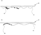
図2(a)は本発明のディスクローディングロールのローディング状態を示す模式図であるが、ローディングロール11の表面に付着した埃12は、ディスク13に擦られて凹部に入り込み、ローディングロール11の表面とディスク13とが直接接触することになり、常に十分なグリップ力が得られるという効果を奏する。
FIG. 2A is a schematic diagram showing the loading state of the disk loading roll of the present invention. The
一方、例えば、図2(b)に示すように、凹凸の十点平均粗さRzは同程度であるが、凹凸の平均間隔Smが15μmより大きく、tpが切断レベル20%で16%以下且つ切断レベル30%で26%以下でないローディングロール01では、表面に付着した埃02は、ローディングロール01とディスク03との間に介在しやすく、十分なグリップ力が得られなくなる。
On the other hand, as shown in FIG. 2B, for example, the ten-point average roughness Rz of the unevenness is approximately the same, but the average interval Sm of the unevenness is larger than 15 μm, and tp is 16% or less at a cutting level of 20%. With the
本発明のディスクローディングロールの凹凸面は、金型による成形により形成される。凹凸面を形成する模様を金型内面に形成する方法は特に限定されないが、サンドブラスト又はショットブラスト処理などの機械加工の他、腐食処理等の化学的処理により簡便且つ低コストで所定の凹凸面を形成することができる。 The uneven surface of the disk loading roll of the present invention is formed by molding with a mold. There is no particular limitation on the method of forming the pattern for forming the uneven surface on the inner surface of the mold, but the predetermined uneven surface can be formed easily and at low cost by chemical processing such as corrosion treatment in addition to mechanical processing such as sand blasting or shot blasting. Can be formed.
上述した凹凸面を金型に形成する方法の一例としては、硬度38(HRC)以上の鋼材を切削加工した金型を用い、これに所定のメディアをブラストする方法を挙げることができる。この場合、角張ったメディア(サンド)で、且つ粒径が50〜300μmの範囲内で、ばらつきを基準粒径で±10%程度有するメディアを用い、ブラスト処理するのが好ましい。用いるメディアの粒径やブラスト処理条件を調整することにより、所望の凹凸を有する金型を成形することができる。また、このような処理をした面に、硬質クロームメッキなどを施すのが好ましい。 As an example of a method for forming the uneven surface described above in a mold, a method in which a mold obtained by cutting a steel material having a hardness of 38 (HRC) or higher is used, and a predetermined medium is blasted to the mold. In this case, it is preferable to perform blasting using an angular medium (sand) and a medium having a particle diameter of 50 to 300 μm and a variation of about ± 10% as a reference particle diameter. By adjusting the particle size of the media to be used and the blasting conditions, it is possible to mold a mold having desired irregularities. Moreover, it is preferable to perform hard chrome plating etc. on the surface which performed such a process.
また、本発明のディスクローディングロールは、EPDM、シリコーン、クロロプレン、NBR等を用いて成形することができる。 The disk loading roll of the present invention can be formed using EPDM, silicone, chloroprene, NBR, or the like.
本発明のディスクローディングロールのゴム硬度は、一般には、ショア Aで30〜90°であるが、特に、40〜60°が好ましい。十分な搬送トルクを得るためである。 The rubber hardness of the disk loading roll of the present invention is generally 30 to 90 ° at Shore A, but 40 to 60 ° is particularly preferable. This is to obtain a sufficient conveyance torque.
以上説明したように、本発明のディスクローディングロールは、表面に所定の凹凸面を有しているので、埃が付着しても凹部に逃げ、搬送トルクが著しく低下せず、長期に亘って安定して使用することができる。 As described above, the disk loading roll of the present invention has a predetermined uneven surface, so even if dust adheres, it escapes into the recess and the transport torque is not significantly reduced and stable for a long time. Can be used.
以下、本発明を実施例に基づいて図面を参照して説明するが、本発明の趣旨に反しない限り、本実施例に限定されることはない。 Hereinafter, the present invention will be described based on examples with reference to the drawings. However, the present invention is not limited to these examples unless it is contrary to the gist of the present invention.
(実施例1〜3及び比較例1〜2)
シリコーンゴム100重量部を用いて、サンドブラスト処理で形成した所定形状の実施例1、実施例2、実施例3、比較例1または比較例2の金型を用いて筒状体を成形した。具体的には170℃で8分間電熱プレスで加硫し、ゴム硬度がショア Aで50°の筒状体を得た。これを突切りして実施例1〜3及び比較例1〜2のディスクローディングロールとした。
(Examples 1-3 and Comparative Examples 1-2)
Using 100 parts by weight of silicone rubber, a cylindrical body was molded using the mold of Example 1, Example 2, Example 3, Comparative Example 1 or Comparative Example 2 having a predetermined shape formed by sandblasting. Specifically, vulcanization was carried out by an electric heating press at 170 ° C. for 8 minutes to obtain a cylindrical body having a rubber hardness of Shore A and 50 °. This was cut off to obtain disk loading rolls of Examples 1 to 3 and Comparative Examples 1 and 2.
(比較例3)
実施例と同様なゴム部材を用いて、鏡面に近い金型で成形して比較例3のディスクローディングロールとした。
(Comparative Example 3)
Using the same rubber member as in the example, the disk loading roll of Comparative Example 3 was formed by molding with a mold close to a mirror surface.
(試験例1)
実施例及び比較例のディスクローディングロールの外表面の表面状態を以下のように測定した。
(Test Example 1)
The surface conditions of the outer surfaces of the disk loading rolls of the examples and comparative examples were measured as follows.
測定器としては、キーエンス社製、超深度形状測定装置(コントローラ部「VK−9500」、測定部「VK−9510」、形状解析アプリケーションVK−H1A9(Ver.2.2)3次元計測・表面積)を用いた。測定条件は以下のとおりである。 As a measuring instrument, manufactured by Keyence Corporation, ultra-deep shape measuring device (controller unit “VK-9500”, measuring unit “VK-9510”, shape analysis application VK-H1A9 (Ver. 2.2) three-dimensional measurement / surface area) Was used. The measurement conditions are as follows.
倍率 3000倍(対物150倍×20)
光学ズーム 1倍
カラー超深度
測定距離 50μm
ピッチ 0.05μm
高さスムージング ±2
面傾き補正 自動
カットオフ値 0.08mm
フィルタ処理 平滑化×3回
Magnification 3000x (objective 150x20)
Optical zoom 1x Ultra deep color Measurement distance 50μm
Pitch 0.05μm
Height smoothing ± 2
Surface tilt correction Automatic cut-off value 0.08mm
Filter
なお、実施例および比較例のディスクローディングロールについて、tpについてはそれぞれ1箇所のサンプリングデータをとり、また、Rz及びSmについてはそれぞれ6箇所のサンプリングデータをとり最大値・最小値・平均値を求めた。 For the disk loading rolls of the example and the comparative example, sampling data at one place is taken for each of tp, and sampling data at six places is taken for each of Rz and Sm to obtain the maximum value / minimum value / average value. It was.
表面粗さRz、凹凸の平均間隔Sm、切断レベル10〜40%でのtpの測定結果を表1に示し、tpについては図3にも示す。また、実施例1及び比較例3については、表面状態の3000倍の写真を図4に示す。 Table 1 shows the measurement results of tp at the surface roughness Rz, the average interval Sm of unevenness, and the cutting level of 10 to 40%, and tp is also shown in FIG. Moreover, about Example 1 and Comparative Example 3, the photograph of 3000 times the surface state is shown in FIG.
この結果、比較例3のローディングロールは緩やかな凹凸を有しているのに対し、実施例のローディングロールは凹凸の間隔が小さく、また、各切断レベルでのtpが小さいため粉塵が落ち込むスペースが大きく、明らかに両者の表面状態は異なっていることがわかった。なお、この結果は表面粗さRzでは差がないが、凹凸の間隔Smの平均値およびtpでは完全に差があることからも明らかである。 As a result, the loading roll of Comparative Example 3 has gentle irregularities, whereas the loading roll of the example has a small interval between the irregularities, and the tp at each cutting level is small, so there is a space for dust to fall. It was clear that the surface conditions of both were clearly different. This result is clear from the fact that there is no difference in the surface roughness Rz, but there is a complete difference in the average value of the unevenness spacing Sm and the tp.
(試験例2)
各実施例及び比較例のディスクローディングロールを、下記の粉塵試験方法の環境下においた機械にて、ローディング、イジェクト動作試験を行った。なお、各実施例及び比較例のディスクローディングロールをそれぞれ20個ずつ作製し、2個ずつロールを用いて各実施例及び比較例とも10回動作試験を行い、動作OKが80%以上の場合を○、動作OKが20%〜79%の場合を△、動作OKが20%未満の場合を×、として評価した。この結果を表1に示す。表1に示すように、tp、Rz及びSmが所定の範囲内である実施例1〜3では、比較例3よりもローディング及びイジェクトの動作性が顕著に良好であり、また、Rz及びSmが本発明の範囲内であるが各切断レベルでのtpが大きく凸部がブロードな凹凸を有する比較例1及び比較例2よりも動作性が良好だった。
(Test Example 2)
The loading and ejecting operation tests were performed on a machine in which the disk loading rolls of the examples and comparative examples were placed in the environment of the following dust test method. In addition, 20 disk loading rolls of each example and comparative example were prepared, and each of the examples and comparative examples was tested ten times using two rolls, and the operation OK was 80% or more. The case where the operation OK was 20% to 79% was evaluated as Δ, and the case where the operation OK was less than 20% was evaluated as X. The results are shown in Table 1. As shown in Table 1, in Examples 1 to 3 in which tp, Rz, and Sm are within a predetermined range, the operability of loading and ejecting is significantly better than that of Comparative Example 3, and Rz and Sm are Although it was within the scope of the present invention, the operability was better than Comparative Example 1 and Comparative Example 2 in which the tp at each cutting level was large and the convex part had broad irregularities.
粉塵試験方法(JIS D 0207 浮遊試験F−3)
ダスト種類 :JIS Z 8901 8種
ダスト濃度 :100mg/m3以上
試験温度 :20±15℃
相対湿度 :45〜85%
攪拌時間 :2秒
休止時間 :10分
繰り返し時間:8時間
なお、JIS Z 8901 8種は、関東ロームで中位径の範囲が6.6〜8.6μmである。
Dust test method (JIS D 0207 Floating test F-3)
Dust type: JIS Z 8901 8 types
Dust concentration: 100 mg / m 3 or more
Test temperature: 20 ± 15 ° C
Relative humidity: 45-85%
Stirring time: 2 seconds
Break time: 10 minutes
Repetition time: 8 hours In addition, JIS Z 8901 8 types are Kanto loam and the range of a median diameter is 6.6-8.6 micrometers.
11 ローディングロール
12 埃
13 ディスク
11
Claims (2)
2. The disk loading roll according to claim 1, wherein the rubber elastic body has a rubber hardness of 30 to 90 degrees on Shore A.
Priority Applications (2)
| Application Number | Priority Date | Filing Date | Title |
|---|---|---|---|
| JP2005036850A JP4172592B2 (en) | 2005-02-14 | 2005-02-14 | Disc loading roll |
| US11/142,376 US20050273795A1 (en) | 2004-06-03 | 2005-06-02 | Disc-loading roll |
Applications Claiming Priority (1)
| Application Number | Priority Date | Filing Date | Title |
|---|---|---|---|
| JP2005036850A JP4172592B2 (en) | 2005-02-14 | 2005-02-14 | Disc loading roll |
Publications (2)
| Publication Number | Publication Date |
|---|---|
| JP2006221778A JP2006221778A (en) | 2006-08-24 |
| JP4172592B2 true JP4172592B2 (en) | 2008-10-29 |
Family
ID=36983975
Family Applications (1)
| Application Number | Title | Priority Date | Filing Date |
|---|---|---|---|
| JP2005036850A Expired - Fee Related JP4172592B2 (en) | 2004-06-03 | 2005-02-14 | Disc loading roll |
Country Status (1)
| Country | Link |
|---|---|
| JP (1) | JP4172592B2 (en) |
Families Citing this family (1)
| Publication number | Priority date | Publication date | Assignee | Title |
|---|---|---|---|---|
| EP2042831A4 (en) | 2006-07-14 | 2010-10-13 | Honda Motor Co Ltd | Navigation server, navigation device, and navigation system |
-
2005
- 2005-02-14 JP JP2005036850A patent/JP4172592B2/en not_active Expired - Fee Related
Also Published As
| Publication number | Publication date |
|---|---|
| JP2006221778A (en) | 2006-08-24 |
Similar Documents
| Publication | Publication Date | Title |
|---|---|---|
| JPH05288221A (en) | Rolling sliding component | |
| JP5936230B2 (en) | Holding jig, handling jig, a set of holding jig, and adherend holding device | |
| JP4172592B2 (en) | Disc loading roll | |
| JP4172591B2 (en) | Disc loading roll | |
| CN103459057A (en) | Method and tool for bending titanium member | |
| JP4172593B2 (en) | Disc loading roll | |
| JP3627866B1 (en) | Disc loading roll | |
| US8146793B2 (en) | Pins for transferring material | |
| JP4135947B2 (en) | Disc loading roll | |
| JP4172590B2 (en) | Disc loading roll | |
| JP2006143471A (en) | Paper feeding roller | |
| JP3932947B2 (en) | Roll surface care apparatus and roll surface care method | |
| JP4623523B2 (en) | Disc loading roll | |
| US20050273795A1 (en) | Disc-loading roll | |
| JP3800423B2 (en) | Disc loading roll | |
| JP4466898B2 (en) | Disc loading roll | |
| JP4466899B2 (en) | Disc loading roll | |
| JP2006344341A (en) | Disk loading roll | |
| JP4466480B2 (en) | Rolling and sliding parts, rolling bearings and cam followers | |
| JP2008019965A (en) | Planetary gear device and rolling bearing | |
| JP2010102327A (en) | Cleaning blade and electrophotographic image forming device using the same | |
| JP4920508B2 (en) | Transfer machine | |
| JP5017948B2 (en) | Method of manufacturing rolling element for rolling support device | |
| JP2010278043A (en) | Handling jig of small component, and handling apparatus of small component | |
| JP2008008455A (en) | Sealed rolling bearing |
Legal Events
| Date | Code | Title | Description |
|---|---|---|---|
| A711 | Notification of change in applicant |
Free format text: JAPANESE INTERMEDIATE CODE: A712 Effective date: 20070511 |
|
| A621 | Written request for application examination |
Free format text: JAPANESE INTERMEDIATE CODE: A621 Effective date: 20071129 |
|
| A977 | Report on retrieval |
Free format text: JAPANESE INTERMEDIATE CODE: A971007 Effective date: 20080729 |
|
| TRDD | Decision of grant or rejection written | ||
| A01 | Written decision to grant a patent or to grant a registration (utility model) |
Free format text: JAPANESE INTERMEDIATE CODE: A01 Effective date: 20080806 |
|
| A01 | Written decision to grant a patent or to grant a registration (utility model) |
Free format text: JAPANESE INTERMEDIATE CODE: A01 |
|
| A61 | First payment of annual fees (during grant procedure) |
Free format text: JAPANESE INTERMEDIATE CODE: A61 Effective date: 20080806 |
|
| R150 | Certificate of patent or registration of utility model |
Free format text: JAPANESE INTERMEDIATE CODE: R150 |
|
| FPAY | Renewal fee payment (event date is renewal date of database) |
Free format text: PAYMENT UNTIL: 20110822 Year of fee payment: 3 |
|
| FPAY | Renewal fee payment (event date is renewal date of database) |
Free format text: PAYMENT UNTIL: 20120822 Year of fee payment: 4 |
|
| FPAY | Renewal fee payment (event date is renewal date of database) |
Free format text: PAYMENT UNTIL: 20120822 Year of fee payment: 4 |
|
| FPAY | Renewal fee payment (event date is renewal date of database) |
Free format text: PAYMENT UNTIL: 20130822 Year of fee payment: 5 |
|
| R250 | Receipt of annual fees |
Free format text: JAPANESE INTERMEDIATE CODE: R250 |
|
| S111 | Request for change of ownership or part of ownership |
Free format text: JAPANESE INTERMEDIATE CODE: R313111 |
|
| S531 | Written request for registration of change of domicile |
Free format text: JAPANESE INTERMEDIATE CODE: R313531 |
|
| R350 | Written notification of registration of transfer |
Free format text: JAPANESE INTERMEDIATE CODE: R350 |
|
| LAPS | Cancellation because of no payment of annual fees |