JP4170644B2 - X-ray diagnostic equipment - Google Patents
X-ray diagnostic equipment Download PDFInfo
- Publication number
- JP4170644B2 JP4170644B2 JP2002073214A JP2002073214A JP4170644B2 JP 4170644 B2 JP4170644 B2 JP 4170644B2 JP 2002073214 A JP2002073214 A JP 2002073214A JP 2002073214 A JP2002073214 A JP 2002073214A JP 4170644 B2 JP4170644 B2 JP 4170644B2
- Authority
- JP
- Japan
- Prior art keywords
- moire
- image data
- angle
- ray
- correction
- Prior art date
- Legal status (The legal status is an assumption and is not a legal conclusion. Google has not performed a legal analysis and makes no representation as to the accuracy of the status listed.)
- Expired - Fee Related
Links
- 238000012937 correction Methods 0.000 claims description 83
- 238000000034 method Methods 0.000 claims description 29
- 238000003860 storage Methods 0.000 claims description 4
- 238000010586 diagram Methods 0.000 description 12
- 238000003384 imaging method Methods 0.000 description 12
- 238000012545 processing Methods 0.000 description 9
- 238000013500 data storage Methods 0.000 description 8
- 230000008569 process Effects 0.000 description 6
- 238000006243 chemical reaction Methods 0.000 description 4
- 238000001514 detection method Methods 0.000 description 4
- 239000000470 constituent Substances 0.000 description 3
- 230000000694 effects Effects 0.000 description 3
- 238000007689 inspection Methods 0.000 description 3
- 238000004519 manufacturing process Methods 0.000 description 3
- 238000009826 distribution Methods 0.000 description 2
- 238000000605 extraction Methods 0.000 description 2
- 238000001914 filtration Methods 0.000 description 2
- 230000004048 modification Effects 0.000 description 2
- 238000012986 modification Methods 0.000 description 2
- 239000004065 semiconductor Substances 0.000 description 2
- RYGMFSIKBFXOCR-UHFFFAOYSA-N Copper Chemical compound [Cu] RYGMFSIKBFXOCR-UHFFFAOYSA-N 0.000 description 1
- BUGBHKTXTAQXES-UHFFFAOYSA-N Selenium Chemical compound [Se] BUGBHKTXTAQXES-UHFFFAOYSA-N 0.000 description 1
- 238000009825 accumulation Methods 0.000 description 1
- 230000002238 attenuated effect Effects 0.000 description 1
- 229910052793 cadmium Inorganic materials 0.000 description 1
- BDOSMKKIYDKNTQ-UHFFFAOYSA-N cadmium atom Chemical compound [Cd] BDOSMKKIYDKNTQ-UHFFFAOYSA-N 0.000 description 1
- 238000004364 calculation method Methods 0.000 description 1
- 230000008859 change Effects 0.000 description 1
- 238000007796 conventional method Methods 0.000 description 1
- 229910052802 copper Inorganic materials 0.000 description 1
- 239000010949 copper Substances 0.000 description 1
- 238000003745 diagnosis Methods 0.000 description 1
- 238000006073 displacement reaction Methods 0.000 description 1
- 230000002526 effect on cardiovascular system Effects 0.000 description 1
- 239000011888 foil Substances 0.000 description 1
- 238000010438 heat treatment Methods 0.000 description 1
- 239000000463 material Substances 0.000 description 1
- 230000007246 mechanism Effects 0.000 description 1
- 229910052751 metal Inorganic materials 0.000 description 1
- 239000002184 metal Substances 0.000 description 1
- 230000005855 radiation Effects 0.000 description 1
- 230000009467 reduction Effects 0.000 description 1
- 229910052711 selenium Inorganic materials 0.000 description 1
- 239000011669 selenium Substances 0.000 description 1
- 238000001228 spectrum Methods 0.000 description 1
Images


Classifications
-
- A—HUMAN NECESSITIES
- A61—MEDICAL OR VETERINARY SCIENCE; HYGIENE
- A61B—DIAGNOSIS; SURGERY; IDENTIFICATION
- A61B6/00—Apparatus or devices for radiation diagnosis; Apparatus or devices for radiation diagnosis combined with radiation therapy equipment
- A61B6/42—Arrangements for detecting radiation specially adapted for radiation diagnosis
- A61B6/4291—Arrangements for detecting radiation specially adapted for radiation diagnosis the detector being combined with a grid or grating
-
- A—HUMAN NECESSITIES
- A61—MEDICAL OR VETERINARY SCIENCE; HYGIENE
- A61B—DIAGNOSIS; SURGERY; IDENTIFICATION
- A61B6/00—Apparatus or devices for radiation diagnosis; Apparatus or devices for radiation diagnosis combined with radiation therapy equipment
- A61B6/52—Devices using data or image processing specially adapted for radiation diagnosis
- A61B6/5258—Devices using data or image processing specially adapted for radiation diagnosis involving detection or reduction of artifacts or noise
Landscapes
- Health & Medical Sciences (AREA)
- Life Sciences & Earth Sciences (AREA)
- Engineering & Computer Science (AREA)
- Medical Informatics (AREA)
- Radiology & Medical Imaging (AREA)
- Molecular Biology (AREA)
- Biophysics (AREA)
- Nuclear Medicine, Radiotherapy & Molecular Imaging (AREA)
- Optics & Photonics (AREA)
- Pathology (AREA)
- Physics & Mathematics (AREA)
- Biomedical Technology (AREA)
- Heart & Thoracic Surgery (AREA)
- High Energy & Nuclear Physics (AREA)
- Surgery (AREA)
- Animal Behavior & Ethology (AREA)
- General Health & Medical Sciences (AREA)
- Public Health (AREA)
- Veterinary Medicine (AREA)
- Computer Vision & Pattern Recognition (AREA)
- Apparatus For Radiation Diagnosis (AREA)
Description
【0001】
【発明の属する技術分野】
本発明は、撮影アングルを変更可能なX線診断装置に関する。
【0002】
【従来の技術】
X線診断装置では、通常、イメージインテンシファイア又はフラットパネル式X線検出器の受像面に、散乱線を除去するためのX線グリッドが配置されている。X線グリッドは、多数の薄板状の金属等の板が格子状又は平行に組まれてなる。従来では、グリッド板の間隔(以下、グリッド密度)が、撮像系の解像度よりも比較的狭かったため、モアレがアーチファクトとして画像に出現することは無かった。
【0003】
しかし、最近の撮像系の高解像化に伴って、グリッドがモアレ状のアーチファクトとして画像に出現するようになった。
【0004】
もちろん、グリッド密度を撮像系が識別できないように狭くすることにより、原理的に、モアレは見かけ上解消される。しかし、現在でもグリッド密度は1cm当たり数十本というオーダで構成されており、これ以上に狭い密度でX線グリッドを構成することは困難であり、また可能であっても製造コストが高くなり過ぎる。従って、グリッドの加工によって当該問題を解決することは、現実的でないのが現状である。
【0005】
また、モアレを画像処理により除去することが、例えば特開平11−146277号公報に開示されている。つまり、被検体ではなく、均質なファントムを撮影すると、基本的にモアレ画像データが得られ、このモアレ画像データを実際に被検体画像データから減算することでモアレ除去が実現され得る。
【0006】
しかし、このモアレ除去方法は、循環器系X線診断等には適用できない場合がある。その最大の理由としては、例えば撮影アングルやSID(Source Image Distance)によってモアレ縞のパターンが様々に変化することにある。
【0007】
【発明が解決しようとする課題】
本発明の目的は、X線診断装置において、モアレ補正精度を向上することにある。
【0008】
【課題を解決するための手段】
本発明はある局面において、X線管球と、X線検出器と、前記X線検出器の受像面に配置されるグリッドと、前記X線管球と前記X線検出器の受像面との間の距離を変更可能に、前記X線管球と前記X線検出器とを支持するアームと、前記アームの角度を変更可能に前記アームを支持するアーム支持装置とを有するX線診断装置のモアレ補正方法において、前記グリッドによるモアレ画像データの複数のファイルが前記アームの角度に関連付けて記憶された記憶装置から、前記アームの角度に応じて選択的にモアレ画像データを読み出し、前記X線検出器から出力される画像データを、前記読み出されたモアレ画像データ基づいて、補正する方法を提供する。
【0009】
【発明の実施の形態】
以下、図面を参照して本発明によるX線診断装置を実施形態により説明する。
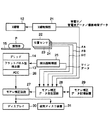
図1には本実施形態によるX線診断装置の架台の構成図を示している。C形又はU形のアーム11の一端にはX線管球12がマウントされる。アーム11の他端には、フラットパネル型検出器(フラットパネルデテクタ)13が、X線管球12に対して対向する向きで、マウントされる。移動機構17は、フラットパネル型検出器13を前後に移動可能に支持する。フラットパネル型検出器13の移動により、フラットパネル型検出器13の受像面とX線管球12との間の距離SID(Source Image Distance)は、変化する。
【0010】
フラットパネル型検出器13には、間接変換型又は直接変換型が採用される。間接変換型のフラットパネル型検出器13は、入射X線を光に変換するシンチレータプレートと、この光を電気信号(電荷)に変換するフォトダイオードアレイとを備えてなる。直接変換のフラットパネル型検出器13は、X線感光材として例えばセレン又はカドミウムを用いた半導体素子アレイを有する。フラットパネル型検出器13の受像面は、シンチレータプレート又は半導体素子アレイの表面として定義される。
【0011】
フラットパネル型検出器13の受像面には、X線グリッド14が配置される。X線グリッド14は、受像面に対して所定角度以上斜めに入射する主に散乱線を除去するために、格子状又は平行にアレンジされた複数の薄い鉛板(グリッド板)を有する。
【0012】
アーム11は、矢印B方向に関して、スライド回転可能にアームホルダ18に支持される。アームホルダ18は、床面上に施設された又は天井から吊り下げられたホルダベース19に矢印Aに関して軸回転可能に支持される。典型的には、矢印Aの回転軸AAと矢印Bの回転軸ABとはアイソセンタICと呼ばれる不動点で直交する。
【0013】
なお、フラットパネル型検出器13が最上位にある位置を基準位置として、その基準位置から矢印A方向に関するアーム11のアングルをθA と表記し、矢印B方向に関するアーム11のアングルをθB と表記する。
【0014】
X線管球12とフラットパネル型検出器13との間には、被検体Pを載置するための天板15が配置される。この天板15は、上下左右に移動可能なように天板ベース16に支持される。
【0015】
図2には本実施形態装置の主要部のブロック図を示している。X線制御部21は、X線管球12の電極間に印加するための高電圧(管電圧)を発生する。また、X線制御部21は、X線管球12のフィラメントを加熱するためのフィラメント電流を発生する。一般的には、X線の線質は、管電圧に応じて変化する。X線の強度は、管電流に応じて変化する。管電流は、フィラメント電流に関連している。X線制御部21は、管電圧データ、管電流のデータ及び撮影時間(X線照射時間)のデータを、モアレ補正データ発生回路28に供給する。
【0016】
アングルθA 、アングルθB 、距離SIDを検出するために、位置センサ22,23,24は、アーム18に取り付けられる。位置センサ22,23,24は、典型的にはロータリエンコーダである。位置センサ22,23,24が検出したアングルデータθA ,θB 、SIDデータは、モアレ補正データ発生回路28に供給される。
【0017】
検出器制御部25は、フラットパネル型X線検出器13の電荷蓄積、信号読出し及びフラットパネル型X線検出器13に組み込まれている前置増幅器のゲインを主に制御する。このゲインデータは、モアレ補正データ発生回路28に供給される。
【0018】
フラットパネル型X線検出器13の出力信号は、アナログディジタル変換器(ADC)26でディジタル信号に変換され、図3に示すように、画像データとしてモアレ補正回路27に供給される。なお、以下の説明で扱われる画像データには、実際の検査対象である被検体PをX線管球12と検出器13との間に配置した状況のもとでの撮影オペレーションにより得られる画像データと、X線管球12と検出器13との間に被検体Pを配置しない状況での撮影オペレーションにより得られる画像データとの大きく2種類が存在する。前者はオリジナル画像データと称する。後者の画像データには、グリッド14の製造誤差に主に起因するモアレ縞が写り込んでいることから、モアレ画像データと称する。
【0019】
モアレ補正回路27は、オリジナル画像データを、モアレ補正データ発生回路28から供給されるモアレ補正データに基づいて補正する。補正されたオリジナル画像データは、ディスプレイ30及び磁気ディスク装置31に出力され、表示及び記録される。
【0020】
なお、グリッド14を検出器13から取り外した状況で、撮影が行われることがある。その状況が図示しないグリッドセンサで検知されたとき、モアレ補正回路27は、オリジナル画像データをディスプレイ30に実質的にスルーさせるように機能する。
【0021】
モアレ画像データ記憶装置29には、図3に示すように、複数のモアレ画像データファイルが保管される。モアレ画像データファイルを発生させるために、X線管球12とフラットパネル型検出器13との間に、天板15及び被検体Pを配置しない状況で、撮影オペレーションが行われる。それによりX線グリッド14によるモアレ縞が主に映った画像データファイル(モアレ画像データファイル)が得られる。モアレ画像データファイルを発生させるための撮影オペレーションは、アングルθA 、アングルθB 、距離SIDの少なくとも1つを変えながら繰り返し行われる。各モアレ画像データファイルには、それを撮影したときの状況、つまりアングルデータθA 、アングルデータθB 及びSIDデータが関連付けられる。複数のモアレ画像データファイルに関連付けられるデータは、互いに、アングルθA 、アングルθB 、距離SIDの少なくとも1つが相違する。
【0022】
なお、従来では、モアレ画像データを取得するための撮影オペレーションは、図4(a)に示すように、X線管球12と検出器13との間に天板15が介在する状況で行われていた。この状況では、図4(b)、図4(c)に示すように、モアレ画像データには天板15の影が映り込んでしまう。この影の部分では、モアレ補正が不可能であった。本実施形態では、この問題を回避するために、モアレ画像データを取得するための撮影は、X線管球12と検出器13との間に天板15及び被検体Pを配置しない状況で、又は管球照射口に銅板等のファントムを張り付けた上で、X線管球12と検出器13との間に天板15及び被検体Pを介在させない状況で行われる。
【0023】
さらに、このようなモアレ画像データを取得するための撮影オペレーションが、図5(a)に示すように、アングルθA 、及びアングルθB が基準位置(共にゼロ度)、さらに距離SIDが基準距離にある状態だけでなく、図5(b)、図5(c)に示すように、アングルθA 、アングルθB 及び距離SIDの少なくとも1つが基準からずれた様々な状況で繰り返される。それにより基準位置に対応するモアレ画像画像データだけでなく、その基準位置からアングルθA 、アングルθB 及び距離SIDの少なくとも1つが少しずつ異なった複数のモアレ画像データファイルが得られる。
【0024】
アングルθA 及び/又はアングルθB を基準位置からずらす、つまりアーム11をA、Bの2方向又はいずれか1方向に傾斜させると、アーム11、X線管球12及び検出器13の重量により、アーム11が歪む。このアーム11の歪みは、モアレ縞を傾斜させまたは歪ませる。また、距離SIDを基準距離よりも短く又は長く変化させると、画像の拡大率が変化する。拡大率が変化すると、モアレ縞の間隔が変化する。つまり、アングルθA 、アングルθB 、距離SIDの少なくとも1つが変化すると、モアレ縞の出現パターンが変化する。
【0025】
従って、アングルθA 、アングルθB 及び距離SIDの少なくとも1つが相違する複数のモアレ画像データファイルを取得しておき、実際の撮影時のアングルθA 、アングルθB 及び距離SIDと同じ又は近似する状況で取得したモアレ画像データファイルを使って、オリジナル画像データを補正することで、モアレの補正精度を向上させることができる。
【0026】
もちろん、実際の撮影時のアングルθA 、アングルθB 及び距離SIDと同じ状況で取得されたモアレ画像データファイルが、モアレ画像データ記憶装置29に記憶されていない場合もある。その場合、モアレ補正データ発生回路28は、実際の撮影時のアングルθA 、アングルθB 及び距離SIDに最も近い状況で取得された1枚のモアレ画像データファイルを選択する。または、モアレ補正データ発生回路28において、実際の撮影時のアングルθA 、アングルθB 及び距離SIDに最も近い状況で取得された2枚又はそれ以上の枚数のモアレ画像データファイルをモアレ画像データ記憶装置29から読み出し、それら複数枚のモアレ画像データファイルから、実際の撮影時のアングルθA 、アングルθB 及び距離SIDに相当するモアレ画像データファイルを、距離線形補間により求めるようにしてもよい。
【0027】
なお、モアレ画像データファイルを取得する撮影状況で、ゲイン、管電圧、管電流及び撮影時間に関しては、それぞれ基準値で固定される。モアレ補正データ発生回路28は、記憶装置29から選択的に読み出したモアレ画像データファイル又は補間により求めたモアレ画像データファイルのコントラストを、実際のゲイン、管電圧、管電流及び撮影時間に基づいて、修正することにより、モアレ補正データを発生する。
【0028】
なお、記憶装置29にはモアレ画像データを保存するようにしたが、モアレ補正データ発生回路28で作成したモアレ補正データを、そのアングル、距離、さらにゲイン、管電圧、管電流、撮影時間に関連付けて保存し、同じ状況で撮影が行われる際にはそのモアレ補正データを再使用するようにしてもよい。
【0029】
このモアレ補正データは、モアレ補正回路27に送られる。オリジナル画像データは、モアレ補正回路27において、モアレ補正データに従って補正される。実際には、オリジナル画像データに対してモアレ補正データを、加算、減算、乗算、又は除算し、または、オリジナル画像データをモアレ補正データに従って対数変換、又は指数変換する。いずれの計算方法を当該補正に適用するかは、任意である。ここでは減算を例に説明する。
【0030】
なお、モアレ補正データ発生処理及びモアレ補正処理は、ハードウエアまたはソフトウエアで実現される。
【0031】
このように天板を介在させない状況でモアレ画像データを発生し、またアームのアングルθA 及びθB 、距離SIDに応じてモアレ画像データを使い分け、さらに管電流、管電圧、ゲイン及び撮影時間に応じてモアレ画像データを修正して補正データを作成することでモアレ補正精度を向上させることができる。
【0032】
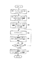
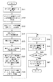
図6には、本実施形態のモアレ補正処理の手順を示している。まず、S1において、モアレ補正データ発生回路28に、被検体Pを撮影アングルθA 、アングルθB 、距離SID、ゲインの各データがセンサ22,23,24から、管電圧、管電流及び撮影時間の情報がX線制御部21から、さらにゲインデータが検出器制御部25から供給される。モアレ補正データ発生回路28は、供給されたアングルθA 、アングルθB 、距離SIDに関連付けられているモアレ画像データをモアレ画像データ記憶装置29から選択的に読み出す(S2)。
【0033】
読み出されたモアレ画像データを、モアレ補正データ発生回路28は、管電圧データ、管電流データ、撮影時間データ、ゲインデータに基づいて、モアレ補正データに変換する(S3)。それによりモアレ画像データのモアレ縞の濃度が、オリジナル画像データのモアレ縞の濃度と等価又は近似される。
【0034】
次に、オリジナル画像データに対してモアレ補正データの空間的な位置ずれを修正するために、ピクセルシフト処理(S4)、減算処理(S5)及び最小化判定処理(S6)がループ状に実行される。図7にその概念を模式的に示している。まず、オリジナル画像データとモアレ補正データとからそれぞれフレーム内の同じ位置の一部分、例えば同じコーナーの部分領域が抽出される。次に、モアレ補正データの部分領域の位置が、モアレ縞に垂直な方向に、Pp/nを単位距離としてシフトされる。Ppは、隣り合う画素のピッチ(例えば中心点間距離)であり、nは位置ずれ修正精度を決める任意の正の整数である。
【0035】
このシフトされたモアレ補正データの部分領域と、オリジナル画像データの部分領域とが差分され、その残差合計が計算される。その残差合計を最小化するように、単位距離Pp/nずつシフトシフト距離を増やしながらピクセルシフト(S4)及び差分(S5)を繰り返す。残差合計が最小化したときのモアレ補正データの部分領域のシフト距離が、オリジナル画像データに対するモアレ補正データの空間的な位置ずれを表している。
【0036】
こうして求めたオリジナル画像データとモアレ補正データとの空間的な位置ずれに従って、一方又は両方をシフトして、差分する(S7)。それによりオリジナル画像データから、モアレ縞が除去又は軽減され得る。
【0037】
なお、グリッド14を取り外して状況で検査撮影が行われることがある。その場合には、モアレ補正処理は必要ない。具体的には、その場合には、オリジナル画像データはモアレ補正回路27を実質的にパスしてディスプレイ30に送られる。実質的にパスするとは、オリジナル画像データは、ADC26からモアレ補正回路27をスルーしてディスプレイ30に直接的に供給されるか、又は補正効果が除去された補正データでオリジナル画像データをモアレ補正回路27で補正するか、のいずれかである。
【0038】
図8には他のモアレ補正処理の手順を示している。上述した図6のモアレ補正処理は、図8に示すモアレ補正処理、さらに後述する図12,図13に示すモアレ補正処理のいずれの手法にも代替え可能である。さらに図6,図8,図12,図13、図14の中の任意の2つ、3つ、4つ又は5つの手法を実施可能に、モアレ補正データ発生回路28及びモアレ補正回路27を構成しておき、いずれか所望の手法を操作者が選択的に適用することを可能としても良い。さらに、図6,図8,図12,図13、図14の中の任意の2つ、3つ、4つ又は5つ全ての手法をオリジナル画像データに対して自動的に適用し、最もモアレ低減効果の良好な手法の画像を操作者が選択するようにしても良い。
【0039】
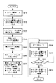
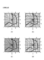
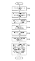
図8に示すように、モアレ補正データ発生回路28には、ADC26からオリジナル画像データが供給される(S11)。モアレ補正データ発生回路28は、オリジナル画像データから、図9(a)、図9(b)、図9(c)、図9(d)に示すように、複数の方向にそれぞれ対応する複数の一次元画像信号を生成する(S12)。複数の方向で複数の一次元画像信号を生成するのは、モアレ縞の方向を特定することを目的としている。
【0040】
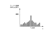
次に、モアレ補正データ発生回路28は、複数の一次元画像信号を個々にフーリエ変換にかける(S13)。フーリエ変換は高速フーリエ変換FFTと離散フーリエ変換DFTとのいずれを採用しても良い。フーリエ変換により、図10に示すように、方向の異なる複数の一次元画像信号にそれぞれ対応する複数の周波数分布が生成される。そして、各周波数分布から、モアレ縞に対応する空間周波数、典型的には強度の最も高いピーク周波数が抽出される(S14)。なお、ここでは、モアレ縞に対応する空間周波数は、画像内の強度の最も高いピーク周波数として現れるものとして説明する。
【0041】
なお、モアレ縞はグリッド14のグリッド板の配列ピッチが検出素子の配列ピッチに対してずれてことを原因として起こる。従って、グリッド板の配列ピッチから、モアレ縞に対応する空間周波数の範囲をある程度絞り込むことができる。それによりモアレ縞に対応する空間周波数を、当該範囲内でピーク周波数を抽出することで、抽出エラーを低減し、また抽出処理を短縮することが可能となる。
【0042】
方向の異なる複数のピーク周波数の中から最も高いピーク周波数が選択され(S15)、選択された最も高いピーク周波数成分の強度が特定される(S16)。この選択された最も高いピーク周波数に対応する方向は、モアレ縞に垂直な方向に対応している。
【0043】
なお、モアレ補正データ発生回路28は、オリジナル画像データに対して2次元フーリエ変換にかけて、その2次元フーリエ変換結果から、ピーク周波数、ピーク周波数成分の強度、そして方向とを検出するようにしても良い。
【0044】
モアレ補正データ発生回路28は、選択された最も高いピーク周波数に対応する方向に沿って、選択された最も高いピーク周波数の逆数の周期で複数のモアレ縞を平行に形成するとともに、そのモアレ縞の濃度を当該ピーク周波数成分の強度に従って設定することにより、図11に示すモアレ補正データを生成する(S17)。
【0045】
オリジナルの画像データに対して、生成したモアレ補正データの位置ずれを、S4,S5,S6と同様に、S18,S19,S20により求め、その位置ずれに従って、一方又は両方をシフトして、差分する(S21)。それによりオリジナル画像データから、モアレ縞が除去又は軽減され得る。
【0046】
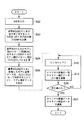
図8の方法では、モアレ補正データ発生回路28において、選択された最も高いピーク周波数に対応する方向と、選択された最も高いピーク周波数と、ピーク周波数成分の強度とに基づいて、モアレ補正データを生成したが、方向及び空間周波数が相違し、一方、濃度は標準的に作成した複数のモアレ標準画像データファイルを作成して、予めデータ記憶装置29に保管させておき、複数のモアレ標準画像データファイルの中から、図12のS22に示すように、S15で実際のオリジナル画像データから求めた最大のピーク周波数とその方向とに対応するモアレ標準画像データファイルを選択的にデータ記憶装置29からモアレ補正データ発生回路28に読み出し、そしてS23において、その読み出したモアレ標準画像データをS16で特定した強度に従ってモアレ縞の濃度を設定することにより、モアレ補正データを生成するようにしても良い。
【0047】
図13の手法は、モアレ画像データ、モアレ標準画像データを必要としない手法である。S15で実際のオリジナル画像データから最大のピーク周波数とその方向が求められている。このピーク周波数はモアレ縞の空間周波数を示している。従って、S24において、求めた方向に関して当該ピーク周波数の空間周波数成分を、S16で特定した濃度の減衰率で減衰するように、空間フィルタリングをオリジナル画像データに対して補正回路27でかける。空間フィルタリングは、ソフトウエアでもハードウエア(FIR又はIIR型の一般的なディジタルフィルタ)でもいずれでも実現可能であり、方向、ピーク周波数、減衰率に応じた係数列がフィルタリングプログラムコード又はディジタルフィルタに与えられる。
【0048】
上述した図6、図8、図12の手法は、複数の距離SIDにそれぞれ対応する複数のモアレ画像データファイル又はモアレ標準画像データファイルを予め用意しておく必要がある。さらに、各距離SIDごとに、様々なアングルのデータファイルが必要となり、そのファイル数は非常に多くなることがある。ファイル数を低減する手法が図14に示されている。その手法は、基準SIDに対応するモアレ画像データを、実際の検査撮影時のSIDに応じて修正することにより、オリジナル画像データに対応するモアレ補正データを生成するものである。実際には、アングルが相違するが、距離SIDは基準値で一定の複数のモアレ画像データファイル又はモアレ標準画像データファイルが用意され、それらのファイルの中から実際のアングルに応じたファイルが選択的に使用される。
【0049】
まず、モアレ補正データ発生回路28には、センサ24から実際の検査撮影時のSIDデータが供給される(S32)。ここで、グリッド14は検出器13の受像面上に装着されるが、グリッド14と検出器13の受像面との間には、構造上及び組み立て工程上避けられないマージンが存在する。つまり、グリッド14は検出器13の受像面から若干離れている。従って、SIDの変化に応じて、モアレ縞のパターン周期は変化する。
【0050】
ここでは、基準SIDに対応するモアレ縞のパターン周期に対する実際のSIDに対応するモアレ縞のパターン周期の比を求め、その比に応じて基準SIDのモアレ画像データファイルをモアレ縞に垂直な方向に伸縮することにより、モアレ補正データを生成するものである。
【0051】
まず、S33において、SIDが基準値S0のときのグリッド14の実体に対する検出器受像面上でのグリッド投影像の拡大率と、SIDが実際値S1のときのグリッド14の実体に対する検出受像面上でのグリッド投影像の拡大率との比M1が、(1)式により計算される。
M1=(S1/(S1−D0))/(S0/(S0−D0)) (1)
なお、D0は、グリッド14と検出受像面との間の物理的な距離を表している。
【0052】
次に、SID=S0のときのモアレ縞のパターン周期C0と、SID=S1のときのモアレ縞のパターン周期C1との比(C1/C0)が計算される(S34)。SID=S0のときのモアレ縞のパターン周期C0は、
C0=(Pg/(Pp−Pg))×Pp (2)
で与えられる。なお、Ppは図15に示すように、検出器13の画素ピッチ(実寸)を表し、PgはSID=S0のときにグリッド13のグリッド板(鉛箔)が検出器13の受像面上に投影されたその投影像のピッチを表している。つまり、モアレ縞は、検出器13の実際の画素ピッチPpに対する受像面上でのグリッド板投影像のピッチPgの製造誤差により生じ、その誤差(Pp−Pg)を単位として累積的に画素に対してグリッド板投影像のずれが増大していく。
【0053】
ここで、SID=S1のとき、受像面上でのグリッド板投影像のピッチは、上記M1により、
Pg×M1
により与えられる。従ってSID=S1のときのモアレ縞のパターン周期C1は、
C1=((Pg×M1)/(Pp−(Pg×M1)))×Pp (3)
で与えられる。
【0054】
(2)式、(3)式から、S34において、
C1/C0=(Pp−Pg)/((Pp/M1)−Pg) (4)
が計算される。
【0055】
以上のように計算されたパターン周期の比C1/C0に従って、基準SID(S0)のときのモアレ画像データをモアレ縞に垂直な一方向に拡大する(S35)。それによりモアレ補正データが生成される。
【0056】
オリジナルの画像データに対して、生成したモアレ補正データの位置ずれを、S4,S5,S6と同様に、S18,S19,S20により求め、その位置ずれに従って、一方又は両方をシフトして、差分する(S21)。それによりオリジナル画像データから、モアレ縞が除去又は軽減され得る。
【0057】
(変形例)
本発明は、上述した実施形態に限定されるものではなく、実施段階ではその要旨を逸脱しない範囲で種々変形して実施することが可能である。さらに、上記実施形態には種々の段階が含まれており、開示される複数の構成要件における適宜な組み合わせにより種々の発明が抽出され得る。例えば、実施形態に示される全構成要件から幾つかの構成要件が削除されてもよい。
【0058】
【発明の効果】
本発明によれば、X線診断装置において、モアレ補正精度を向上することができる。
【図面の簡単な説明】
【図1】本発明の実施形態に係るX線診断装置の架台の構成図。
【図2】本実施形態に係るX線診断装置の主要部のブロック図。
【図3】図2のモアレ画像データ記憶装置に記憶されるモアレ画像データの例を示す図。
【図4】従来のモアレ画像データの撮影方法の説明図。
【図5】図3のモアレ画像データの撮影方法の説明図。
【図6】本実施形態において、第1の補正手順を示すフローチャート。
【図7】本実施形態において、図6のS4,S5,S6の処理の概念図。
【図8】本実施形態において、第2の補正手順を示すフローチャート。
【図9】図8の一次元画像信号の生成方向を示す図。
【図10】図8のフーリエ変換による一次元画像信号の周波数スペクトルの例を示す図。
【図11】図8の生成されたモアレ補正データを示す図。
【図12】本実施形態において、第3の補正手順を示すフローチャート。
【図13】本実施形態において、第4の補正手順を示すフローチャート。
【図14】本実施形態において、第5の補正手順を示すフローチャート。
【図15】図14の補足図。
【符号の説明】
12…X線管球、
13…フラットパネル型X線検出器、
14…グリッド、
15…天板、
18…アーム、
21…X線制御部、
22…位置センサ、
23…位置センサ、
24…位置センサ、
25…検出器制御部、
26…アナログディジタル変換器、
27…モアレ補正回路、
28…モアレ補正データ発生回路、
29…モアレ画像データ記憶装置、
30…ディスプレイ、
31…磁気ディスク装置。[0001]
BACKGROUND OF THE INVENTION
The present invention relates to an X-ray diagnostic apparatus capable of changing an imaging angle.
[0002]
[Prior art]
In the X-ray diagnostic apparatus, an X-ray grid for removing scattered radiation is usually arranged on the image receiving surface of an image intensifier or a flat panel X-ray detector. The X-ray grid is formed by assembling a large number of thin plates of metal or the like in a lattice shape or in parallel. Conventionally, since the interval between grid plates (hereinafter, grid density) is relatively narrower than the resolution of the imaging system, moire did not appear as an artifact in the image.
[0003]
However, with the recent increase in resolution of the imaging system, the grid has appeared in the image as moire-like artifacts.
[0004]
Of course, moire is apparently eliminated by narrowing the grid density so that the imaging system cannot be identified. However, even today, the grid density is configured on the order of several tens of grids per 1 cm, and it is difficult to configure an X-ray grid with a density narrower than this, and even if possible, the manufacturing cost becomes too high. . Therefore, at present, it is not practical to solve the problem by processing the grid.
[0005]
Further, removal of moire by image processing is disclosed in, for example, Japanese Patent Application Laid-Open No. 11-146277. That is, when a homogeneous phantom is photographed instead of the subject, moire image data is basically obtained, and moire removal can be realized by actually subtracting this moire image data from the subject image data.
[0006]
However, this moire removal method may not be applicable to cardiovascular X-ray diagnosis or the like. The biggest reason is that the pattern of moire fringes varies depending on, for example, the shooting angle and SID (Source Image Distance).
[0007]
[Problems to be solved by the invention]
An object of the present invention is to improve the moire correction accuracy in an X-ray diagnostic apparatus.
[0008]
[Means for Solving the Problems]
In one aspect of the present invention, an X-ray tube, an X-ray detector, a grid disposed on an image receiving surface of the X-ray detector, an X-ray tube and an image receiving surface of the X-ray detector An X-ray diagnostic apparatus comprising: an arm that supports the X-ray tube and the X-ray detector so that the distance between them can be changed; and an arm support device that supports the arm so that the angle of the arm can be changed. In the moire correction method, the moire image data is selectively read according to the angle of the arm from a storage device in which a plurality of files of moire image data by the grid are stored in association with the angle of the arm, and the X-ray detection is performed. There is provided a method for correcting image data output from a device based on the read moire image data.
[0009]
DETAILED DESCRIPTION OF THE INVENTION
Hereinafter, an X-ray diagnostic apparatus according to the present invention will be described with reference to the drawings.
FIG. 1 is a configuration diagram of a gantry of the X-ray diagnostic apparatus according to the present embodiment. An
[0010]
The
[0011]
An
[0012]
The
[0013]
The position at which the
[0014]
Between the
[0015]
FIG. 2 shows a block diagram of the main part of the apparatus of this embodiment. The
[0016]
In order to detect the angle θA, the angle θB, and the distance SID, the
[0017]
The
[0018]
The output signal of the flat
[0019]
The
[0020]
Note that photographing may be performed in a situation where the
[0021]
The moire image
[0022]
Conventionally, an imaging operation for acquiring moire image data is performed in a situation where a
[0023]
Further, as shown in FIG. 5A, the photographing operation for acquiring such moire image data is such that the angle θA and the angle θB are at the reference position (both are zero degrees), and the distance SID is at the reference distance. As shown in FIG. 5B and FIG. 5C, not only the state but also at least one of the angle θA, the angle θB, and the distance SID is repeated in various situations. Thereby, not only the moire image image data corresponding to the reference position but also a plurality of moire image data files in which at least one of the angle θA, the angle θB and the distance SID is slightly different from the reference position.
[0024]
When the angle θA and / or the angle θB is shifted from the reference position, that is, when the
[0025]
Therefore, a plurality of moire image data files having at least one of the angle θA, the angle θB, and the distance SID are acquired and acquired in a situation that is the same as or similar to the angle θA, the angle θB, and the distance SID at the time of actual shooting. By correcting the original image data using the moiré image data file, the moiré correction accuracy can be improved.
[0026]
Of course, the moire image
[0027]
It should be noted that the gain, tube voltage, tube current, and shooting time are fixed at reference values in the shooting situation in which the moire image data file is acquired. The moiré correction
[0028]
Although the moire image data is stored in the
[0029]
The moire correction data is sent to the
[0030]
The moire correction data generation process and the moire correction process are realized by hardware or software.
[0031]
In this way, moire image data is generated in a state where no top plate is interposed, and moire image data is selectively used according to arm angles θA and θB and distance SID, and further according to tube current, tube voltage, gain and shooting time. The moire correction accuracy can be improved by correcting the moire image data and creating correction data.
[0032]
FIG. 6 shows the procedure of moire correction processing of the present embodiment. First, in S1, the moiré correction
[0033]
The moire correction
[0034]
Next, a pixel shift process (S4), a subtraction process (S5), and a minimization determination process (S6) are executed in a loop to correct the spatial misalignment of the moire correction data with respect to the original image data. The FIG. 7 schematically shows the concept. First, a part of the same position in the frame, for example, a partial area of the same corner, is extracted from the original image data and the moire correction data. Next, the position of the partial area of the moire correction data is shifted in the direction perpendicular to the moire fringes with Pp / n as a unit distance. Pp is the pitch of adjacent pixels (for example, the distance between the center points), and n is an arbitrary positive integer that determines the misalignment correction accuracy.
[0035]
The partial area of the shifted moire correction data and the partial area of the original image data are subtracted, and the residual sum is calculated. The pixel shift (S4) and the difference (S5) are repeated while increasing the shift shift distance by the unit distance Pp / n so as to minimize the residual sum. The shift distance of the partial area of the moire correction data when the residual sum is minimized represents the spatial displacement of the moire correction data with respect to the original image data.
[0036]
One or both of the original image data and the moire correction data obtained in this way are shifted to make a difference (S7). Thereby, moire fringes can be removed or reduced from the original image data.
[0037]
In some cases, the
[0038]
FIG. 8 shows another moire correction processing procedure. The above-described moire correction processing of FIG. 6 can be replaced with any of the moire correction processing shown in FIG. 8 and the moire correction processing shown in FIGS. Further, the moire correction
[0039]
As shown in FIG. 8, the original image data is supplied from the
[0040]
Next, the moire correction
[0041]
Moire fringes are caused by the shift of the grid plate arrangement pitch of the
[0042]
The highest peak frequency is selected from a plurality of peak frequencies in different directions (S15), and the intensity of the selected highest peak frequency component is specified (S16). The direction corresponding to the selected highest peak frequency corresponds to the direction perpendicular to the moire fringes.
[0043]
The moire correction
[0044]
The moiré correction
[0045]
Similar to S4, S5, and S6, the positional deviation of the generated moire correction data is obtained from the original image data by S18, S19, and S20, and one or both of them are shifted according to the positional deviation and the difference is obtained. (S21). Thereby, moire fringes can be removed or reduced from the original image data.
[0046]
In the method of FIG. 8, the moire correction
[0047]
The method of FIG. 13 is a method that does not require moire image data and moire standard image data. In S15, the maximum peak frequency and its direction are obtained from the actual original image data. This peak frequency indicates the spatial frequency of moire fringes. Therefore, in S24, the
[0048]
In the methods shown in FIGS. 6, 8, and 12 described above, it is necessary to prepare a plurality of moire image data files or moire standard image data files respectively corresponding to a plurality of distance SIDs. Furthermore, data files of various angles are required for each distance SID, and the number of files may be very large. A technique for reducing the number of files is shown in FIG. In this method, moire correction data corresponding to the original image data is generated by correcting the moire image data corresponding to the reference SID in accordance with the SID at the time of actual inspection photographing. Actually, the angles are different, but a plurality of moire image data files or moire standard image data files whose distance SID is a reference value are prepared, and a file corresponding to the actual angle is selectively selected from these files. Used for.
[0049]
First, the moiré correction
[0050]
Here, the ratio of the moire fringe pattern period corresponding to the actual SID to the moire fringe pattern period corresponding to the reference SID is obtained, and the moire image data file of the reference SID is oriented in a direction perpendicular to the moire fringe according to the ratio. Moire correction data is generated by expanding and contracting.
[0051]
First, in S33, the magnification ratio of the grid projection image on the detector image receiving surface for the entity of the
M1 = (S1 / (S1-D0)) / (S0 / (S0-D0)) (1)
D0 represents a physical distance between the
[0052]
Next, a ratio (C1 / C0) between the moire fringe pattern period C0 when SID = S0 and the moire fringe pattern period C1 when SID = S1 is calculated (S34). The pattern period C0 of moire fringes when SID = S0 is
C0 = (Pg / (Pp-Pg)) * Pp (2)
Given in. As shown in FIG. 15, Pp represents the pixel pitch (actual size) of the
[0053]
Here, when SID = S1, the pitch of the grid plate projection image on the image receiving surface is determined by the above M1.
Pg x M1
Given by. Therefore, the moire fringe pattern period C1 when SID = S1 is
C1 = ((Pg × M1) / (Pp− (Pg × M1))) × Pp (3)
Given in.
[0054]
From the equations (2) and (3), in S34,
C1 / C0 = (Pp-Pg) / ((Pp / M1) -Pg) (4)
Is calculated.
[0055]
In accordance with the pattern cycle ratio C1 / C0 calculated as described above, the moire image data at the reference SID (S0) is expanded in one direction perpendicular to the moire fringes (S35). Thereby, moire correction data is generated.
[0056]
Similar to S4, S5, and S6, the positional deviation of the generated moire correction data is obtained from the original image data by S18, S19, and S20, and one or both of them are shifted according to the positional deviation and the difference is obtained. (S21). Thereby, moire fringes can be removed or reduced from the original image data.
[0057]
(Modification)
The present invention is not limited to the above-described embodiments, and various modifications can be made without departing from the scope of the invention at the stage of implementation. Furthermore, the above embodiment includes various stages, and various inventions can be extracted by appropriately combining a plurality of disclosed constituent elements. For example, some constituent requirements may be deleted from all the constituent requirements shown in the embodiment.
[0058]
【The invention's effect】
According to the present invention, it is possible to improve the moire correction accuracy in the X-ray diagnostic apparatus.
[Brief description of the drawings]
FIG. 1 is a configuration diagram of a gantry of an X-ray diagnostic apparatus according to an embodiment of the present invention.
FIG. 2 is a block diagram of the main part of the X-ray diagnostic apparatus according to the present embodiment.
FIG. 3 is a diagram showing an example of moire image data stored in the moire image data storage device of FIG. 2;
FIG. 4 is an explanatory diagram of a conventional method for capturing moire image data.
FIG. 5 is an explanatory diagram of a method for capturing the moire image data in FIG. 3;
FIG. 6 is a flowchart showing a first correction procedure in the present embodiment.
7 is a conceptual diagram of the processing of S4, S5, and S6 in FIG. 6 in the present embodiment.
FIG. 8 is a flowchart showing a second correction procedure in the present embodiment.
9 is a diagram illustrating a generation direction of the one-dimensional image signal in FIG.
10 is a diagram illustrating an example of a frequency spectrum of a one-dimensional image signal obtained by Fourier transform in FIG. 8;
11 is a diagram showing the generated moire correction data of FIG. 8. FIG.
FIG. 12 is a flowchart showing a third correction procedure in the present embodiment.
FIG. 13 is a flowchart showing a fourth correction procedure in the present embodiment.
FIG. 14 is a flowchart showing a fifth correction procedure in the embodiment.
15 is a supplementary diagram of FIG.
[Explanation of symbols]
12 ... X-ray tube,
13: Flat panel X-ray detector,
14 ... Grid,
15 ... top plate,
18 ... arm,
21 ... X-ray control unit,
22: Position sensor,
23 ... Position sensor,
24 ... position sensor,
25. Detector control unit,
26: Analog to digital converter,
27. Moire correction circuit,
28: Moire correction data generation circuit,
29. Moire image data storage device,
30 ... Display,
31: Magnetic disk device.
Claims (1)
前記グリッドによるモアレ画像データの複数のファイルが前記アームの角度に関連付けて記憶された記憶装置から、前記アームの角度に応じて選択的にモアレ画像データを読み出し、
前記X線検出器から出力される画像データを、前記読み出されたモアレ画像データ基づいて、補正することを特徴とするモアレ補正方法。The distance between the X-ray tube, the X-ray detector, the grid arranged on the image receiving surface of the X-ray detector, and the distance between the X-ray tube and the image receiving surface of the X-ray detector can be changed. In the moiré correction method for an X-ray diagnostic apparatus, comprising: an arm that supports the X-ray tube and the X-ray detector; and an arm support device that supports the arm so that the angle of the arm can be changed.
Moire image data is selectively read according to the angle of the arm from a storage device in which a plurality of files of moire image data by the grid are stored in association with the angle of the arm;
A moire correction method comprising correcting image data output from the X-ray detector based on the read moire image data.
Priority Applications (1)
| Application Number | Priority Date | Filing Date | Title |
|---|---|---|---|
| JP2002073214A JP4170644B2 (en) | 2001-03-16 | 2002-03-15 | X-ray diagnostic equipment |
Applications Claiming Priority (3)
| Application Number | Priority Date | Filing Date | Title |
|---|---|---|---|
| JP2001-75962 | 2001-03-16 | ||
| JP2001075962 | 2001-03-16 | ||
| JP2002073214A JP4170644B2 (en) | 2001-03-16 | 2002-03-15 | X-ray diagnostic equipment |
Publications (3)
| Publication Number | Publication Date |
|---|---|
| JP2002336220A JP2002336220A (en) | 2002-11-26 |
| JP2002336220A5 JP2002336220A5 (en) | 2005-08-25 |
| JP4170644B2 true JP4170644B2 (en) | 2008-10-22 |
Family
ID=26611429
Family Applications (1)
| Application Number | Title | Priority Date | Filing Date |
|---|---|---|---|
| JP2002073214A Expired - Fee Related JP4170644B2 (en) | 2001-03-16 | 2002-03-15 | X-ray diagnostic equipment |
Country Status (1)
| Country | Link |
|---|---|
| JP (1) | JP4170644B2 (en) |
Families Citing this family (12)
| Publication number | Priority date | Publication date | Assignee | Title |
|---|---|---|---|---|
| JP2005109908A (en) * | 2003-09-30 | 2005-04-21 | Konica Minolta Medical & Graphic Inc | Image processor and image processing program |
| JP2006014778A (en) * | 2004-06-30 | 2006-01-19 | Shimadzu Corp | Moire removing method and radiography apparatus using the same |
| DE602006004101D1 (en) * | 2005-04-14 | 2009-01-22 | Agfa Healthcare Nv | Method for suppressing a periodic pattern in an image |
| JP4946927B2 (en) * | 2008-03-13 | 2012-06-06 | 株式会社島津製作所 | X-ray tomography equipment |
| US8538118B2 (en) * | 2008-04-22 | 2013-09-17 | Shimadzu Corporation | Method of removing moiré in fluoroscopic X-ray image and X-ray imaging equipment using the same |
| JP5239585B2 (en) * | 2008-07-28 | 2013-07-17 | 株式会社島津製作所 | X-ray imaging device |
| JP5455446B2 (en) | 2009-06-02 | 2014-03-26 | キヤノン株式会社 | Radiation imaging apparatus, control method and program for radiation imaging apparatus |
| JP5375655B2 (en) | 2010-02-18 | 2013-12-25 | 株式会社島津製作所 | Radiography equipment |
| JP5407937B2 (en) * | 2010-03-02 | 2014-02-05 | 株式会社島津製作所 | X-ray equipment |
| JP5479243B2 (en) * | 2010-06-25 | 2014-04-23 | 富士フイルム株式会社 | Radiographic image processing apparatus, radiographic image capturing system, and program |
| US8897418B2 (en) | 2012-08-15 | 2014-11-25 | Shimadzu Corporation | X-ray apparatus |
| US20230030175A1 (en) * | 2021-07-27 | 2023-02-02 | GE Precision Healthcare LLC | Method and systems for removing anti-scatter grid artifacts in x-ray imaging |
-
2002
- 2002-03-15 JP JP2002073214A patent/JP4170644B2/en not_active Expired - Fee Related
Also Published As
| Publication number | Publication date |
|---|---|
| JP2002336220A (en) | 2002-11-26 |
Similar Documents
| Publication | Publication Date | Title |
|---|---|---|
| JP4170644B2 (en) | X-ray diagnostic equipment | |
| US4841555A (en) | Method and system for removing scatter and veiling glate and other artifacts in digital radiography | |
| WO2013005833A1 (en) | X-ray imaging device and calibration method therefor | |
| JP2000333939A (en) | X-ray diagnostic apparatus | |
| JPH10305030A (en) | Radiographic device and driving method for the same | |
| JPH06259541A (en) | Method for correcting image distorting and its system | |
| JP5848697B2 (en) | X-ray diagnostic imaging equipment | |
| JPH02237277A (en) | X-ray diagnostic device | |
| US6480574B2 (en) | X-ray diagnostic apparatus | |
| JP3880117B2 (en) | Image reading method and apparatus | |
| JPWO2004105609A1 (en) | X-ray diagnostic imaging equipment | |
| JP4357050B2 (en) | Method and apparatus for x-ray imaging with anti-scatter grid | |
| KR19990077059A (en) | Stripe Suppression Filter for Computed Tomography System | |
| JP5238175B2 (en) | X-ray diagnostic imaging equipment | |
| JP2005058309A (en) | Cone beam x-ray ct device and phantom used for the same | |
| JPH0815182A (en) | Method for compensating for radiation scattering in x-ray imaging system | |
| JPWO2019073760A1 (en) | X-ray phase contrast imaging system and phase contrast image correction method | |
| JP3755144B2 (en) | Radiography equipment | |
| JP4500400B2 (en) | Image acquisition apparatus and image acquisition method | |
| JP5239585B2 (en) | X-ray imaging device | |
| JP4754812B2 (en) | X-ray equipment | |
| JP2003033348A (en) | Three dimensional x-ray ct scanner | |
| JP2000083946A (en) | Method and device for correction projection and radiation tomography apparatus | |
| JPH04307035A (en) | Radiographic apparatus | |
| JP3884929B2 (en) | Radiation image acquisition apparatus and design method |
Legal Events
| Date | Code | Title | Description |
|---|---|---|---|
| A521 | Request for written amendment filed |
Free format text: JAPANESE INTERMEDIATE CODE: A523 Effective date: 20050222 |
|
| A621 | Written request for application examination |
Free format text: JAPANESE INTERMEDIATE CODE: A621 Effective date: 20050222 |
|
| A131 | Notification of reasons for refusal |
Free format text: JAPANESE INTERMEDIATE CODE: A131 Effective date: 20070227 |
|
| A521 | Request for written amendment filed |
Free format text: JAPANESE INTERMEDIATE CODE: A523 Effective date: 20070425 |
|
| A131 | Notification of reasons for refusal |
Free format text: JAPANESE INTERMEDIATE CODE: A131 Effective date: 20071225 |
|
| A521 | Request for written amendment filed |
Free format text: JAPANESE INTERMEDIATE CODE: A523 Effective date: 20080218 |
|
| TRDD | Decision of grant or rejection written | ||
| A01 | Written decision to grant a patent or to grant a registration (utility model) |
Free format text: JAPANESE INTERMEDIATE CODE: A01 Effective date: 20080805 |
|
| A01 | Written decision to grant a patent or to grant a registration (utility model) |
Free format text: JAPANESE INTERMEDIATE CODE: A01 |
|
| A61 | First payment of annual fees (during grant procedure) |
Free format text: JAPANESE INTERMEDIATE CODE: A61 Effective date: 20080807 |
|
| FPAY | Renewal fee payment (event date is renewal date of database) |
Free format text: PAYMENT UNTIL: 20110815 Year of fee payment: 3 |
|
| R151 | Written notification of patent or utility model registration |
Ref document number: 4170644 Country of ref document: JP Free format text: JAPANESE INTERMEDIATE CODE: R151 |
|
| FPAY | Renewal fee payment (event date is renewal date of database) |
Free format text: PAYMENT UNTIL: 20110815 Year of fee payment: 3 |
|
| FPAY | Renewal fee payment (event date is renewal date of database) |
Free format text: PAYMENT UNTIL: 20120815 Year of fee payment: 4 |
|
| FPAY | Renewal fee payment (event date is renewal date of database) |
Free format text: PAYMENT UNTIL: 20120815 Year of fee payment: 4 |
|
| FPAY | Renewal fee payment (event date is renewal date of database) |
Free format text: PAYMENT UNTIL: 20130815 Year of fee payment: 5 |
|
| S111 | Request for change of ownership or part of ownership |
Free format text: JAPANESE INTERMEDIATE CODE: R313117 Free format text: JAPANESE INTERMEDIATE CODE: R313111 Free format text: JAPANESE INTERMEDIATE CODE: R313114 |
|
| R371 | Transfer withdrawn |
Free format text: JAPANESE INTERMEDIATE CODE: R371 |
|
| S111 | Request for change of ownership or part of ownership |
Free format text: JAPANESE INTERMEDIATE CODE: R313111 Free format text: JAPANESE INTERMEDIATE CODE: R313117 Free format text: JAPANESE INTERMEDIATE CODE: R313114 |
|
| R350 | Written notification of registration of transfer |
Free format text: JAPANESE INTERMEDIATE CODE: R350 |
|
| S533 | Written request for registration of change of name |
Free format text: JAPANESE INTERMEDIATE CODE: R313533 |
|
| R350 | Written notification of registration of transfer |
Free format text: JAPANESE INTERMEDIATE CODE: R350 |
|
| LAPS | Cancellation because of no payment of annual fees |