JP4169569B2 - Recording method, recording medium, and recording / reproducing apparatus - Google Patents
Recording method, recording medium, and recording / reproducing apparatus Download PDFInfo
- Publication number
- JP4169569B2 JP4169569B2 JP2002304289A JP2002304289A JP4169569B2 JP 4169569 B2 JP4169569 B2 JP 4169569B2 JP 2002304289 A JP2002304289 A JP 2002304289A JP 2002304289 A JP2002304289 A JP 2002304289A JP 4169569 B2 JP4169569 B2 JP 4169569B2
- Authority
- JP
- Japan
- Prior art keywords
- recording
- data
- data unit
- unit
- pru
- Prior art date
- Legal status (The legal status is an assumption and is not a legal conclusion. Google has not performed a legal analysis and makes no representation as to the accuracy of the status listed.)
- Expired - Fee Related
Links
Images


Landscapes
- Television Signal Processing For Recording (AREA)
- Signal Processing For Digital Recording And Reproducing (AREA)
- Management Or Editing Of Information On Record Carriers (AREA)
Description
【0001】
【発明の属する技術分野】
本発明は、映像データ、音声データをハードディスク、光ディスク等のランダムアクセス可能な記録媒体に対して記録・再生する処理に関する。
【0002】
【従来の技術】
ディスクメディアを用いたビデオや音声のディジタル記録再生装置が普及しつつある。それらにおいて、テープメディアと同様アフターレコーディング(アフレコ)機能を安価に実現する技術が求められている。アフレコ機能は、既に記録したオーディオやビデオに対し、後から情報、特にオーディオを追記する機能である。
【0003】
ディスクメディアでアフレコ機能を実現している従来技術として、特開平5-234084号公報がある。この技術は、プログラム提示期間よりデータの読込期間が短いことを利用して、現在提示しているディスクからメモリにデータを読み込んでから次のデータを読み込むまでの間に、入力されたアフレコ音声データをディスクに書き込むというもので、ディスク記録再生手段が1つであってもアフレコを実現することが可能である。
【0004】
ここでプログラム提示期間とは、ビデオや音楽などプログラムそれぞれが持つ固有の再生期間のことである。例えば1分間のビデオは、再生手段が変わったとしても1分間で再生されなければ正確に再生されたとは言えない。
【0005】
従来技術におけるディスクの記録フォーマットを図22に示す。ディスクはECC(エラー・コレクション・コーディング)ブロックの列で構成される。ECCブロックは符号化を行う際の最小単位であり、データに加えエラー補正用のパリティが付加され、符号化がおこなわれている。データを読み込む際は、この単位で読み込み誤り訂正をしてから、必要なデータを取り出す。一方、データを書き換える際は、まずECCブロック単位で読み込み、誤り訂正をしたデータに対し、必要な部分を書き換え、再度誤り符号の付与を行ない、ディスクに記録を行なう。このことは、1バイト書き換える場合でも、そのバイトが含まれるECCブロック全体を読み込み書き込む必要があることを意味する。
【0006】
ビデオやオーディオはECCブロック中で、図22 (b)のように、アフレコオーディオブロック、オリジナルオーディオブロック、オリジナルビデオブロックの順に配置される。それぞれのブロックにはほぼ同じ時間に対応するアフレコオーディオ、オリジナルオーディオ、オリジナルビデオが含まれている。なお、オリジナルオーディオブロックとオリジナルビデオブロックを合わせてオリジナルブロックと呼ぶことにする。オリジナルプログラム(アフレコオーディオを記録する前の映像)を記録する際は、アフレコオーディオブロックにダミーのデータを書き込んでおく。
【0007】
次に、従来技術におけるアフレコ時の動作について図23に沿って説明する。図中、上段のグラフは各手段と、その各手段と記録媒体上の関係を示している。中段は、ディスク中でのヘッドの位置を、下段のグラフはバッファメモリ108に占めるプログラムデータの割合を模式的に示したものである。
【0008】
ここではプログラムが、ディスク中のs11〜s18〜の連続的な領域に配置され、s11〜s13、s13〜s15、s15〜s17がそれぞれECCブロックに対応し、s11〜s12、s13〜s14、s15〜s16、s17〜s18がそれぞれアフレコオーディオブロックに対応しているとする。
【0009】
時刻t1の時点ですでにs13までの領域がバッファメモリ108に格納されており、s11〜s13に記録されていたデータがデコードされ提示(再生)されるとともに、そのデータのアフレコ音声の入力、エンコードが行われている。
【0010】
時刻t1〜t3において、領域s13〜s15のデータをディスクから読み込み、バッファメモリ108及びアフレコバッファへの格納を行う。アフレコバッファは読み込んだECCブロックをそのまま記憶し、図22 (b)と同様の構成をとる。
【0011】
時刻t2は、時刻t1の時点で行われていたs11〜s13に記録されていたデータのデコード、再生が終了する時刻である。時刻t2以降は、時刻t1〜t3で読み込まれるs13〜s15のデータをデコード、再生するとともに、そのデータのアフレコ音声の入力、エンコードが行われる。このs13〜s15のデータのデコード、再生はt5まで行われる。
【0012】
t2までに入力されたアフレコ音声は、少なくともt3までにエンコードが終了する。時刻t3において、t2までに入力されたアフレコ音声をディスク媒体に記録する。このときに、s11にアクセスする際に、ディスクの回転待ちの時間を要するが、ディスクの読み書きの時間に比べると、短時間であるので、ここでは考慮しない。
【0013】
アフレコ音声のディスクへの書き込みは、時刻t3〜t4で行われる。このディスクへの書き込みがt4で終了すると、t4からs15〜s17のデータをディスクから読み込む。このように以下同様の処理を繰り返す。
【0014】
この従来技術では、情報圧縮を行うことにより、データの再生時間よりも読み込み時間が短くなることを利用し、記録再生手段を、記録と再生で時分割して利用することで、1つの記録再生手段だけでアフレコを実現している。
【0015】
【発明が解決しようとする課題】
上記したように、ECCブロック毎に誤り訂正符号化が行われるため、ECCブロック中の1バイトを書き換える場合であっても、そのバイトが含まれるECCブロック全体を読み込み書き込む必要がある。上記した従来技術のようにアフレコオーディオデータがECCブロックに分散して配置されていた場合、アフレコオーディオデータを記録するためには、ほとんどのECCブロック、つまりはデータの全てを書き換える必要がある。このように、多くのECCブロックを書き換えてアフレコを行う場合には、読み書き速度の高いディスクドライブを使用するか、読み書きするデータ量を削減することになる。
【0016】
読み書き速度の高いディスクドライブは低いものに比べて高価なものになる。また、ディスクの回転数を高くする必要があるため、消費電力も高くなる。一方、もし速度の低いディスクドライブでアフレコを実現しようとすると、画質を落としてデータ量を削減することになる。
【0017】
本発明は、かかる従来技術の問題点に鑑みてなされたものであり、ECCブロック単位でしか記録再生できない場合に、データ転送速度の比較的低いディスクドライブでも、オリジナルビデオとの時間的ずれがなくしかも画質を落とさずにアフレコを実現することを目的とする。
【0018】
【課題を解決するための手段】
本発明は、記録再生手段を用いて、映像データまたは音声データからなる第1のデータユニットと、前記第1のデータユニットと同期して再生されるデータからなる第2のデータユニットとを光ディスクである記録媒体に記録する記録再生方法であって、
複数からなる前記第1のデータユニットと、該第1のデータユニットに対して後から追記された場合の前記第2のデータユニットとを編集ユニットとして管理し、
前記第1のデータユニットを再生しながら前記第2のデータユニットを記録する際、前記編集ユニットを構成する前記第1のデータユニットの全再生時間を、
記録媒体に対する前記記録再生手段のデータ入出力におけるデータ転送速度、前記記録再生手段が記録媒体にアクセスするときのシーク時間、前記記録再生手段がアクセスする際の記録媒体の回転待ち時間、前記記録再生手段における第1のデータユニットの再生ビットレート及び第2のデータユニットの記録ビットレートのうちの少なくとも1つに基づいて、前記第1のデータユニットの再生や前記第2のデータユニットの記録に途切れがない最小値を求め、該最小値以上になるように決定するものである。
【0019】
また、本発明は、記録再生手段を用いて、映像データまたは音声データからなる第1のデータユニットと、前記第1のデータユニットと同期して再生されるデータからなる第2のデータユニットとを光ディスクである記録媒体に記録する記録媒体であって、
複数からなる前記第1のデータユニットと、該第1のデータユニットに対して後から追記された場合の前記第2のデータユニットとを編集ユニットとして管理し、
前記第1のデータユニットを再生しながら前記第2のデータユニットを記録する際、前記編集ユニットを構成する前記第1のデータユニットの全再生時間を、
記録媒体に対する前記記録再生手段のデータ入出力におけるデータ転送速度、前記記録再生手段が記録媒体にアクセスするときのシーク時間、前記記録再生手段がアクセスする際の記録媒体の回転待ち時間、前記記録再生手段における第1のデータユニットの再生ビットレート及び第2のデータユニットの記録ビットレートのうちの少なくとも1つに基づいて、前記第1のデータユニットの再生や前記第2のデータユニットの記録に途切れがない最小値を求め、該最小値以上になるように決定し記録するものである。
【0020】
さらに、本発明は、映像データまたは音声データからなる第1のデータユニットと、前記第1のデータユニットと同期して再生されるデータからなる第2のデータユニットとを入力する入力手段と、
複数からなる前記第1のデータユニットと、該第1のデータユニットに対して後から追記された場合の前記第2のデータユニットとを編集ユニットとして管理して符号化する符号化手段と、
前記編集ユニットを記録媒体に記録再生する記録再生手段とを備えた記録再生装置であって、
前記符号化手段は、
前記第1のデータユニットを再生しながら前記第2のデータユニットを記録する際、前記編集ユニットを構成する前記第1のデータユニットの全再生時間を、
記録媒体に対する前記記録再生手段のデータ入出力におけるデータ転送速度、前記記録再生手段が記録媒体にアクセスするときのシーク時間、前記記録再生手段がアクセスする際の記録媒体の回転待ち時間、前記記録再生手段における第1のデータユニットの再生ビットレート及び第2のデータユニットの記録ビットレートのうちの少なくとも1つに基づいて、前記第1のデータユニットの再生や前記第2のデータユニットの記録に途切れがない最小値を求め、該最小値以上になるように決定するものである。
【0022】
本発明は、映像または音声からなる第1のデータ(オリジナルデータ)と、前記第1のデータと同期して再生される第2のデータ(アフレコデータ)とを、記録媒体に記録する記録方法であって、所定の再生時間分の前記第1のデータと、該第1のデータに同期して再生される前記第2のデータを第1のユニット(EU(Editable Unit))として管理し、複数の前記第1のユニットから構成されるデータストリームにおいて、前記第1のユニットの再生時間を同一とし、前記第1のユニットの再生時間を、記録媒体への入出力時におけるデータ転送時間、シーク時間、回転待ち時間、第1のデータ或いは第2のデータのビットレートのうちの1に基づいて決定するものである。
【0025】
【発明の実施の形態】
本発明の第1の実施形態を説明する。図 1は、第1の実施形態におけるアフレコ可能なビデオディスクレコーダの構成である。図に示すように、この装置は、操作部101、CPU102、RAM103、ROM104,システムクロック105、バッファメモリ108、エンコーダ106、マルチプレクサ107、ディスクドライブ109、バス110、デマルチプレクサ111、デコーダ112、ディスク113 、ECCエンコーダ/デコーダ114から構成される。
【0026】
ディスク113は、外周から内周に向かって螺旋状に記録再生の行われる脱着可能な光ディスクとする。2048byteを1セクタとし、誤り訂正のため16セクタでECCブロックを構成する。ECCブロック中のデータを書き換える場合、そのデータが含まれるECCブロック全体を読み込み、誤り訂正を行い、対象のデータを書き換え、再び誤り訂正符号を付加し、ECCブロックを構成し記録媒体に記録する必要がある。
【0027】
ディスク113の構成を図 2に示す。ディスク中の先頭にはファイルシステム管理情報があり、その残りがファイルシステムによってファイル単位に管理されるユーザ領域となっている。ユーザ領域は管理情報領域とAVストリーム領域に分けられる。管理情報領域には管理情報に関するファイルが含まれ、AVストリーム領域には、EUS(エディタブル・ユニット・シーケンス)ファイルがある。EUSファイルは、ビデオの記録を開始してから終了するまでの一連のビデオ・オーディオデータを記録したデータストリーム単位のファイルである。一方、管理情報領域のファイルには、EUSファイルに関する情報を格納したEUS Managementファイルなどが含まれる。
【0028】
本実施形態では、ファイルシステム管理情報によって管理されるファイルシステムを通して各ファイルのアクセスを行なう。そのため、図中のEUSファイル#2のようにディスク中で分散して配置されたファイルを、連続した論理アドレスでアクセスすることが可能である。論理アドレスでのアクセスの際の単位はセクタ単位である。なお、本実施例では、発明に直接関係しないためファイルシステムに関する説明は省略する。また、以下の説明におけるアドレスは特に断りが無い限り論理アドレスのことを指すこととする。
【0029】
本実施例で用いる符号化方法に関して説明する。オリジナルビデオは、MPEG-2符号化により5Mbps前後の可変レートで符号化し、オーディオはオリジナル、アフレコともに、48kHzでサンプリングし、MPEG-1/LayerII符号化により2チャンネル256kbpsの固定レートで符号化する。
【0030】
EUSファイルは、ビデオおよびオーディオ情報の多重化データストリームの単位であるEUSを格納するファイルである。EUSのおおまかな構成を図 3に示す。EUSを構成する主な要素について、以下にまとめる。
【0031】
Block:セクタに対応した2048byteの固定長の単位であり、ISO/IEC 13818-2に規定されるビデオデータおよびISO/IEC 13818-3に規定されるオーディオデータおよび他のデータを、ISO/IEC 13818-1で規定されるPES Packetにパケット化したもので構成される
VU (Video Unit):再生時におけるランダムアクセスの単位であり、VUの先頭からアクセスすればEUSの途中であってもオーディオ、ビデオが正しくデコードされることが保証される。Blockで構成される
PRU (Post Recording Unit):複数のVUに関連するポストレコーディングデータ(アフレコデータ)を記録するための領域である。Blockで構成される
EU (Editable Unit):複数のVUとそれに対応する0個または1個のPRUで構成される。1つのEUはディスク中で連続的に記録する
EUS (Editable Unit Sequence): Rec Start〜StopあるいはPauseの区間に相当する単位であり、整数個のEUで構成される。
【0032】
図中のblockは、2048byteの固定長の単位であり、1blockは1セクタに格納される。1個のblockは原則として1個のパケットで構成される。ここでのパケットは、ISO/IEC 13818-1で規定されるPES packetに準拠する。パケットの構成を図 4に示す。パケットは、そのパケットに関する属性等を格納するパケットヘッダとビデオデータ等の実際のデータを格納するパケットデータで構成される。パケットヘッダに含まれる主な情報は以下の通りである。packet-start-code-prefixはISO/IEC 13818-1で規定されたパケットの開始コードである。stream-idはこのパケットの種類を表わす。PES-packet-lengthはこのフィールド以降のデータのサイズを表わす。PES-header-data-lengthはパケットヘッダのサイズを表わす。PTS(プレゼンテーション・タイム・スタンプ)は、多重化したオーディオやビデオといったエレメンタリ・ストリーム間の同期情報であり、パケット中に先頭が含まれるアクセスユニット(ビデオの場合1フレーム)が再生されるタイミングを90kHzのクロックでカウントした値を33ビットで表わしたものである。DTS(デコーディング・タイム・スタンプ)は、そのパケット中に先頭があるアクセスユニットがデコードされるタイミングをPTSと同じ時間軸で表わしたものである。stuffing-bytesは、次に説明するようにパケットのサイズを調整するために用いられる。
【0033】
もし、パケットが2048byteに満たず、不足分が7byte未満のときはパケットヘッダにスタッフィング・バイトを入れる。一方不足分が8byte以上のときは不足分に相当するパディングパケットをそのパケットの後に置く。このスタッフィング・バイト、パディングパケットは実際に処理を行わないいわゆるダミーデータである。本実施例で用いるパケットを以下にまとめる。
【0034】
V-PKT (Video Packet): ISO/IEC 13818-2で規定されるビデオデータを格納したパケット
A-PKT (Audio Packet): ISO/IEC 13818-3で規定されるオーディオデータを格納したパケット
P-PKT (Padding Packet): ISO/IEC 13818-1で規定されるパディング用パケット
VH-PKT (VU Header Packet): VUに関するヘッダを格納したパケット
PH-PKT (PRU Header Packet): PRUに関するヘッダを格納したパケット
V-PKT、A-PKTおよびP-PKTのフォーマットはISO/IEC 13818-1の規定に準拠する。その他のパケットのフォーマットについては後述する。また、EUSを構成するblockを以下にまとめる。
【0035】
V-BLK (Video Block): V-PKTを格納したblock
A-BLK (Audio Block): A-PKTを格納したblock
P-BLK (Padding Block): P-PKTを格納したblock
VH-BLK (VU Header Block): VH-PKTを格納したblock
PH-BLK (PRU Header Block): PH-PKTを格納したblock
まず、EUについて説明する。EUの構造を図 5に示す。EUは1個以上の整数個のVUと0個または1個のPRUを含む。1個のEUSを構成するVUの提示時間は同一にする。つまり、1つのEUSにおけるVUの再生間隔は常に同一となっている。ただし、EUSの最後のVUは他のVUより短くてもよい。
【0036】
なお、VUの提示時間は、そのVUがビデオデータを含む場合は、そのVUに含まれるビデオフィールド数あるいはビデオフレーム数にそれぞれビデオフィールド周期あるいはビデオフレーム周期をかけたものとして定義する。
【0037】
1個のEUSを構成するEUは、すべてPRUを含むか、すべてPRUを含まないかのいずれかにする。EUを構成するVUの個数Nvuは、EUSの最後のEUを除きEUS内では一定にする。つまり、1つのEUSにおいて、EUの提示時間間隔は常に一定となる。PRUを持たないEUSの場合、VU を多数設ける必要がないので、Nvu=1とする。一方、PRUを持つEUSの場合、VUあたりの提示時間をTpv、回転待ち時間をTv、現在読込中のトラックからアフレコ領域のあるトラックへジャンプする時間をTk、ディスクからのデータ転送速度をRs、EUS全体のビットレートをRo、アフレコ音声のチャンネルあたりのビットレートをRa、アフレコ音声のチャンネル数をNchとしたとき、
【0038】
【数1】

とする。なお、ceiling(x)はx以上の最小の整数を、floor(x)はx以下の最大の整数を求める関数である。PRUを持つEUSの場合にデータ転送速度などに基づきNvuの最小値を設定する理由は、EUあたりの時間が十分に大きくないと、図 23のように逐次的にアフレコを行なう際、ヘッドを現在の読込位置からアフレコ領域へ移動させるオーバーヘッドの占める割合が大きくなり、データの読込が表示に追いつかなくなりビデオやオーディオの再生が途切れてしまうからである。
【0040】
次にVUについて説明を行なう。VUは、sequence-headerおよびそれに続くGOP-headerを直前に置いた1個以上の整数個のGOP(グループ・オブ・ピクチャ)からなるビデオデータと、それと同期する整数個のAAU(オーディオ・アクセス・ユニット)からなるオーディオデータを含む。GOPは、MPEGビデオ圧縮の単位で、複数のフィールド群あるいはフレーム群で構成される。AAUは、オーディオサンプルを0.024秒毎にセグメント化しそれぞれのセグメントを圧縮したものである。GOP、AAUともにそれぞれの単位の先頭からデコードする必要があるが、VUはそれぞれを整数個含んでいるためVU単位で独立再生可能である。1VUあたりのビデオフィールド数はNTSCの場合、24フィールドから60フィールド、PALの場合は20フィールドから50フィールドの範囲にする。
【0041】
VUは図 6のように、先頭にVU Header Block(VH-BLK)、次に前述のオーディオデータを格納したA-BLKの列を置き、最後に前述のビデオデータを格納したV-BLKの列の順に配置する。A-BLKの個数は、前述のオーディオデータを格納するのに必要十分なものにする。最後のA-BLKに余りが出た場合には前述のようにP-PKTあるいはスタッフィングバイトで調整する。V-BLKも同様の構成とする。
【0042】
上記のように独立再生が可能な単位であるVUの集合でEUを構成することによって、EUの途中から再生を開始する場合のオーバーヘッドが小さくなる。転送速度がデータのビットレートに比べ余裕が無い場合、Nvuを大きく、すなわちEUあたりの提示時間を長く設定する必要があるが、その場合にVUのような単位を設けなければ、例えばEUの終端付近から再生を始める場合でも、EUの先頭から読み込まなければならず、ユーザに対するレスポンスの低下を招くことになる。また、VUを整数個のblock、すなわちセクタで構成することで、VUの先頭へのアクセスが簡略化される。
【0043】
VH-PKTの構造を図 7に示す。図中のBP(バイト・ポジション)は先頭からの相対的なバイト位置であり、バイト数はそれぞれのフィールドのバイト数を示す。packet-start-code-prefix、stream-id、PES-packet-lengthは前述の通りである。VU Propertyは1byteのビットフィールドで、このVU headerが含まれるVUに関する情報を格納する。その中の1つであるFirst VU of EUはそのVH-PKTを含むVUがEU中の先頭のVUであれば1それ以外は0に設定される。このフィールドは、後述するように、アフレコ時に同期を取るのに用いる。Length of VUはこのVU headerが含まれるVU中のblock数を表わす。Start RLBN of Video Dataは、VUの先頭からビデオデータが始まるまでのblock数を表わす。
【0044】
次にPRUについて説明を行なう。PRUは、1以上整数個のVUに対するオーディオを格納するための領域であり、1個のEUに0個あるいは1個存在する。PRUのサイズは、EUあたりの提示時間に対応するオーディオデータとPRUヘッダ・ブロックを含むことのできる最小の整数個のECCブロックである。PRUを構成するECCブロックの数NPRU,ECCは
【0045】
【数2】
として規定される。なお、PRU中に記録するオーディオデータは、そのPRUが含まれるEU中のVUのオーディオと同じデータレート、同じサンプリング周波数で記録する。
【0047】
オリジナルデータ記録直後のPRUの構成を図 8に示す。先頭にPRU Header Block (PH-BLK)を1個記録し、残りの領域をPadding Block (P-BLK)で埋めておく。つまり、オリジナルデータ記録直後の時点では、オーディオデータは記録されていない。
【0048】
PRUにオーディオをアフレコした後のPRUの構成を図 9に示す。先頭にPRU Header Block (PH-BLK)を1個記録し、その後にはそのEUに同期したオーディオデータをA-BLKの列として記録し、残りの領域をP-BLKで埋めておく。このとき、PRU中のA-BLKは、同じEU中のそれぞれのVUに含まれるA-BLK数の合計と同じ数にする。さらに、PRU中のそれぞれのA-BLKの持つPTSの値が同EU中のそれぞれのVUに含まれるA-BLKのPTSと同じ順番でかつ、同じ値を取るように、ポストレコーディングのオーディオデータを記録する。すなわち、アフレコ後PRU中には、各VUに含まれるA-BLKの列に対応するA-BLKの列が存在することになる。このような、VUに対応したPRU中のA-BLKの列をSAU(サブ・オーディオ・ユニット)と呼ぶことにする。なお、言うまでもないが、SAUには、VUと同様整数個のAAUが含まれることになる。
【0049】
PH-PKTの構造を図 10に示す。packet-start-code-prefix、stream-id、PES-packet-lengthについてはVUヘッダ・パケットと同様である。Length of PRUは、このPH-PKTの含まれるPRUを構成するblock数を記述する。Number of VUはこのPH-BLKの含まれるEUを構成するVUの数を表わす。Start RLBN of Data for VUは、各SAUのPRUの先頭からのblock数を表わす。
【0050】
上記のように、PRUを整数個のBlockすなわちセクタで構成される整数個のAAUを含む単位(SAU)の集合とすることで、PRUをバッファメモリ108に読み込んだ後、その中のアフレコデータをSAU単位で部分的に書き換えることが容易になる。なぜなら、各SAUに含まれるAAUは他のSAU中のAAUとは独立したパケットに格納されているため、SAU単位で書き換えるのであれば、その他のSAUには影響を与えることはないからである。もし、このような構成を取らなければ、1つのパケットに異なるSAUに含まれるAAUが存在することになり、すでにアフレコ済みのPRUに対してその途中からアフレコを行なう際に、パケットを解いてAAUの先頭を探し、データを書き換え再度パケット化するという手順を踏まねばならず、処理が複雑化する。
【0051】
さらに、それぞれのSAUの先頭位置を示す情報をストリーム中に挿入しているため、PRUをSAU単位で書き換えする場合に、どの位置から書き換えを開始したらよいかが即座にわかる。
【0052】
また、PRU中のデータをVU中のオーディオデータと同様の構造にしておくことで、例えば、PRU中のオーディオデータをVU中に部分的にコピーする等、PRUとVUの間でのデータのやり取りが容易になる。
【0053】
EU中でのPRUの配置について説明する。PRUは、それが含まれるEUの先頭の15セクタ以内のECC境界、つまりEU中の最初に現れるECC境界に置く。例えば、あるEUの先頭がECCブロック境界だった場合、図 11 (a)のように、そのEUの先頭の直後にPRUを配置する。また、EUの先頭がECCブロック境界でなかった場合は、(b)のように、EUの境界の直後から15論理ブロック以内のECCブロック境界、つまりEU中の最初に現れるECCブロック境界に配置する。この場合、EU中の先頭のVUはPRUによって分断されることになる。
【0054】
上記のように、PRUのサイズをECCブロックサイズの整数倍にし、なおかつPRUをECCブロック境界に配置することで、アフレコの際は、記録媒体上で書き換えるデータはPRUだけになり、書き換えを行なう領域が最小限で済むという利点がある。
【0055】
上記実施例において、PRUがEUの先頭付近にある理由は、あるEUを再生する場合に、PRU全体と1つのVUを読み込んだ時点でVUとPRUの同期再生が可能になるためである。もし、PRUがEUの終端付近にあった場合、そのEUのほとんどのデータを読み終わるまでプログラムの再生ができず、しかもほぼEU全体を記憶するためのバッファメモリが必要となる。
【0056】
EUS Managementファイルの構造を図 12に示す。EUS Managementファイルは、ディスク中に記録されたすべてのEUSファイルを管理するための情報を格納したものである。以下、本実施形態の説明に必須な項目のみについて説明を行なう。フィールドNumber of EUSIは、このファイルで管理するEUSファイルの個数を表わす。フィールドEUSI(EUS Information)は各EUSファイルに関する情報であり、Number of EUSI個分存在する。EUSIはさらに図 13のように構成される。図中のStart PTおよびEnd PTは、このEUSIが管理するEUSファイル中のの開始PTSおよび終了PTSの最上位ビットを省略したものである。なお、以後このようにPTSの最上位ビットを省略した形式をPTフォーマットと呼ぶことにする。Post Recording Unit SizeはこのEUSIが管理するEUSファイル中のPRUのサイズを表わす。
【0057】
Address LUT(ルックアップ・テーブル)は、PTフォーマットで記述されたタイムコードからそのタイムコードに対応するデータが記録されているアドレスを検索するためのテーブルである。Address LUTの構成を図 14に示す。フィールドPB Time of EUは、EUあたりの提示時間を1/90000[秒]単位で表わしたものであり、PTフォーマットと同じスケールとなっている。PB Time of VUも、同様にVUあたりの提示時間を1/90000[秒]単位で表わしたものである。Number of PRU InformationはAddress LUT中のPRU Informationの数であると同時に、EUS中のPRUの個数も表わす。Number of VU Informationも同様にAddress LUT中のVU Informationの数およびEUS中のVU数を表わしている。
【0058】
図 15は、PRU Informationの内容を表わす。図中のRLBN of PRUはそのPRU Informationが管理するPRUのアドレスを表わす。図 16は、VU Informationの内容を表わす。図中のRLBN of VUはそのVU Informationが管理するVUのアドレスを表わす。
【0059】
Address LUTを用いて、あるタイムコードPTに対応するPRUのアドレスを求める手順を以下に示す。まず、PTからEUSI中のStartPTを引くことで相対PTを求め、次に相対PTをPB Time of EUで割り、小数部を切り捨てることで、そのPTに対応するPRUを管理するPRU Informationのインデックスが求まる。次に、そのインデックスに対応するPRU Information中のRLBN of PRUで与えられるアドレスが、目的とするPTに対応するPRUのアドレスである。時刻PTに対応するVUのアドレスも同様に、PTからStart PTを引いたものをPB Time of VUで割り、小数部を切り捨てた値に対応するインデックスのVU Information中のRLBN of VUを参照することで得られる。このように単純な処理でVUやPRUの先頭アドレスが得られるのは、EUおよびVUあたりの提示時間を一定にしているためである。
【0060】
上記ディスクフォーマットで記録、再生およびアフレコを行なう際の手順を以下に示す。なお、以下の説明ではビデオはNTSCで記録し、VUを30フィールドからなる1個のGOPで構成し、ビデオ最大ビットレートを8[Mbps]とする。ディスク転送レートRsは12[Mbps]、アフレコ領域への最大ジャンプ時間Tkを0.3[秒]、最大回転待ち時間Tvを0.2[秒]とする。また、オーディオビットレートおよびオーディオチャンネル数をそれぞれ0.125[Mbps/チャンネル]、2[チャンネル]とし、オリジナルおよびアフレコで共通に用いることにする。このとき、VUあたりの提示時間Tpvは約0.5秒となる。また、アフレコが可能なEUあたりのVU数Nvuの範囲は、7≦Nvu≦20となる。本実施形態では、Nvu=8、すなわちEUあたりの提示時間は約4秒となる。
【0061】
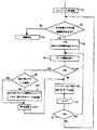
オリジナルプログラム記録時のCPU102の処理の流れを図 17に沿って説明する。すでに、ディスクからEUS Managementファイルやファイルシステム管理情報がRAM103に読み込まれているものとする。CPU102はエンコーダ106を起動し(ステップ1)、次にファイルシステム管理情報を基に1EU分のデータを記録するのに十分な連続領域がディスク上にあるかどうか調べる(ステップ2)。もし、なければ録画を停止する(ステップ12)。
【0062】
もし十分な領域があれば、記録対象のVUがEU中の何番目のVUかを表わす変数iを0にリセットし、空き領域先頭アドレスを変数addrに記憶させる(ステップ3)。次に、マルチプレクサ107から1VU分のデータがバッファメモリ108にバッファリングされたことの通知を待つ(ステップ4)。マルチプレクサ107から通知が来たら、変数iが0のときは(ステップ5)、変数addrがECCブロック境界かどうかを判断し(ステップ9)、もし、ECCブロック境界でなければ、次のECCブロック境界までバッファメモリ108中のVUデータをディスクに記録する(ステップ10)。
【0063】
次に、PH-PKTおよびP-PKTでPRUをRAM103中に構成し、それをディスクに記録する(ステップ11)。次に、バッファメモリ108中の先頭のVUデータをディスクに記録する(ステップ6)。記録が終わったら変数iをインクリメントする(ステップ7)。変数iがEU中のVU数を表わす変数Nvuより小さければステップ4にジャンプし(ステップ8)、等しくなればステップ2にジャンプする。以上の処理を、操作部101から停止指令がきたり、ディスク中に十分な連続領域が無くなるまで、EU単位に行なっていく。
【0064】
以上のCPU102の処理と並行して、マルチプレクサ107は、オーディオ、ビデオそれぞれのエンコーダ106から送られるデータにPTS等を付与しパケット化しバッファメモリ108に貯えていく。1GOP分のV-PKTとそれに同期するA-PKTがバッファメモリ108に貯えられたらCPU102にVU分のデータをバッファリングしたことを通知する。
【0065】
以上の手順で記録を行なったオリジナルプログラムの再生時にユーザからアフレコ開始の指示が与えられた場合の処理の流れを説明する。すでに、ディスクからEUS Managementファイルおよびファイルシステム管理情報がRAM103に読み込まれているものとする。CPU102はデコーダ112を起動し、ファイルシステム管理情報を基に、指定されたEUSファイルを先頭から読み込むようにディスクドライブ109に指令を出す。ディスクドライブ109はECCデコーダ112を経由してデマルチプレクサ111に読み込んだデータを送り、デマルチプレクサ111は、バッファメモリ108にデータを蓄積していく。デコーダ112は、ビデオやオーディオの再生に必要なデータをデマルチプレクサ111に要求し、デマルチプレクサ111はその要求に応じてバッファメモリ108に蓄積したデータを、パケットヘッダ中のstream-idに基づき適切なデコーダ112に送る。デコーダ112はデマルチプレクサ111から十分なデータを受け取りビデオやオーディオを出力可能になった時点でそのデータに対応するPTSでシステムクロック105を初期化し、以後は、システムクロック105の値を基準にして出力の同期を取る。
【0066】
デマルチプレクサ111は、ユーザからアフレコが指示されたときのために現在再生中のデータに対応するPRUと、その次に再生するEUに対応するPRUの合計2個のPRUを常にバッファメモリ108内に保持する。さらに、それらのPRUを管理するためのテーブル(PRU管理テーブル)をRAM103中に作成する。
【0067】
PRU管理テーブルの構成を図 18に示す。PRU管理テーブルは2個のテーブル、SAU開始PTS(SAU-PTS[j][i])とSAU開始アドレス(RLBN[j][i])とで構成される。SAU-PTS[j][i]は2次元の配列であり、1番目のインデックスがバッファメモリ108中のPRUの番号、2番目のインデックスがPRU中のSAUの番号を表わしており、その2つのインデックスでSAUの先頭のPTSを得ることができる。RLBN[j][i]も同様の構造を持ち、PRUの番号とPRU中のSAUの番号をインデックスとし、そのPRUの先頭を基準としたSAUの相対アドレスを得ることが可能である。この2つのテーブルを用いることで、あるPTSに対応するデータをバッファメモリ108中のどのSAUに記録すればよいかがわかる。
【0068】
以上の再生処理を行なっている最中に、ユーザから操作部101を通じてアフレコを行なう指示が与えられた場合の処理を説明する。まず、CPU102がオーディオのエンコーダ106を起動する。デマルチプレクサ111は、システムクロック105からアフレコが開始された時点のタイムスタンプ(アフレコ開始PTS)を得、前述のSAU-PTS[j][i]の中から、アフレコ開始PTSを超えない最大のPTSを持つインデックスを検索する。検索の結果得られたPRU番号n、SAU番号mをデマルチプレクサ111はアフレコ開始PTSとともにマルチプレクサ107に通知する。マルチプレクサ107は、エンコーダ106から送られるAAUをバッファメモリ108中のn番目のPRUのRLBN[n][m]の位置から記憶していく。記録を開始するSAUの先頭PTSとアフレコ開始PTSの差に応じて、パケット化の前にマルチプレクサ107はオーディオエンコーダ106から送られるAAUの前に、無音のAAUを差に相当する分挿入してタイミングを調整する。
【0069】
ユーザからアフレコが指示された時点のシステムクロック105の値、すなわちアフレコ開始PTSが228228だった場合を例に取って説明する。まず、SAU-PTS[i][j]中でアフレコ開始PTSを超えない最大のSAU開始PTSを持つSAU番号、PRU番号の組を検索する。図 18の場合、PRU番号=0、SAU番号=5となる。次にその番号に対応するRLBN[0][5]の値を見る。その結果、SAU#5のアドレス41が得られる。したがって、バッファメモリ108中のPRU#0の先頭から第41 block目に存在するSAU#5からアフレコデータを記録していくことになる。
【0070】
アフレコデータを格納中のPRUのインデックスをnとしたとき、そのPRUの最後までデータを格納した時点で、i=0から7までのRLBN[n][i]の値を現在のPRU中のPH-PKTのフィールドStart RLBN of Data for VUに順に格納し、PRUの最後までデータが格納されたことをCPU102に通知する。その際、SAU-PTS[n][0]、すなわちそのPRUを含むEUの先頭PTSも知らせる。一方、CPU102は、前記のオリジナルプログラムの再生を行ないながら、マルチプレクサ107からの通知があったら、その際に得られるEUの先頭PTSを基に、Address LUTを参照して、そのアフレコオーディオデータを記録すべきディスク113上のPRUのアドレスを求め、ディスクドライブ109に、バッファメモリ108中のn番目のPRUを前記アドレスに記録するように指令を出す。以降は、バッファメモリ中のPRUに入力されるアフレコデータを交互に格納していくことになる。
【0071】
PRU管理テーブルの作成手順を図 19に示す。基本的な考え方は、各VUに含まれるA-BLKの個数をVH-PKT中のStart RLBN of Videoから求め、その個数がSAUに含まれるA-BLKの個数と同じことを利用して、SAU先頭アドレステーブルを構築し、同時にVU中の最初のA-PKTのPTSを抜き出しSAU先頭PTSテーブルを構築することにある。まず、VH-PKTの直後であることを表わすフラグであるVH-flgをリセットし、バッファメモリ108中のPRU番号を指すインデックスであるjを1にセットする(ステップ1)。デマルチプレクサ111に到着したパケットがVH-PKTの場合(ステップ2)、ステップ3にジャンプし、そうでないならステップ7にジャンプする。
【0072】
パケットがVH-PKTの場合、VH-PKT中のFirst VU of EUフィールドが1かどうか検査し(ステップ3)、1なら、それ以降のデータを格納する領域を現在のPRUからもう一方のPRUを変更するために、jをインクリメントする。同時に、RLBN[j][0]に1をセットする。さらに、一時変数tmpに現在のVH-PKT中のStart RLBN of Videoフィールドの値をセットし、iに0をセットする(ステップ4)。もし、FirstVU of EUフィールドが0なら、RLBN[j][i]に一時変数tmpをセットし、さらにtmpに現在のVH-PKT中のStart RLBN of Videoフィールドの値から1引いたものを加える(ステップ6)。ここで1を引くのは、VU中のA-BLKの個数にVH-BLKの個数1を加えた値であるStart RLBN of Videoから、ここで必要となるVU中のA-BLKの個数を求めるために、VH-BLKの分を差し引くことを意味する。First VU of EUフィールドがいずれの場合も次に、VH-flgに1をセットし、iをインクリメントする(ステップ5)。
【0073】
ステップ7では、デマルチプレクサ111に到着したパケットがA-PKTかどうか検査し、A-PKTならステップ8へジャンプし、A-PKTでないならステップ2にジャンプする。ステップ8では、変数VH-flgを検査し、VH-flgが1ならば、そのパケットのパケットヘッダ中のPTSをSAU-PTS[j][i]にセットし、VH-flgを0にリセットする(ステップ9)。以上の処理をblock毎に行なうことで、EUをすべて読み込んだ時点で、そのEU中のPRUに対するPRU管理テーブルを作成することができる。
【0074】
以上のアフレコの際のディスク中のヘッド位置とバッファメモリ108中に占めるオリジナルデータ量の時間的変化について図 20に沿って説明する。ここではプログラムが、ディスク中のs11〜s18〜の連続的な領域に配置され、s11〜s13、s13〜s15、s15〜s17がそれぞれEUに対応し、s11〜s12、s13〜s14、s15〜s16、s17〜s18がそれぞれPRUに対応しているとする。
【0075】
時刻t1の時点では、既にs13までの領域をすべてバッファメモリ108に読み込み、領域s11〜s13のビデオの提示およびそれを見ながらのアフレコオーディオの入力を行っているとする。入力されたアフレコオーディオはバッファメモリ108中の一方のPRU(PRU#0)に格納されているとする。
【0076】
時刻t1〜t3では、ディスクドライブ109が領域s13〜s15を読み込む。時刻t2は、時刻t1までに読み込まれた領域s12〜s13のVUがビデオ再生のために使い果たされる時間に対応する。
【0077】
時刻t3は、領域s12〜s13のVUの提示を見て入力されたアフレコオーディオのエンコーディングが終了する時刻に相当する。この時点で、PRU#0の最後までデータが記録され、マルチプレクサ107はそのPRUの先頭PTSをCPU102に通知し、アフレコオーディオの格納先をもう一方のPRU(PRU#1)に切り替える。
【0078】
ここでは、時刻t3でディスクからの読み込みと、アフレコオーディオのエンコーディングが同時に終了するようになっているが、必ずしも同時である必要はないことは言うまでもない。
【0079】
CPU102はマルチプレクサ107から送られた先頭PTSからPRU#0の内容を記録すべきアドレス、すなわち領域s11〜s12のアドレスを求め、時刻t3〜t4でPRU#0の内容をディスク113に記録する。
【0080】
時刻t5では次の領域s15〜s17の読み込みを行う。このタイミングはt4で書き込み終了後であればよく、バッファメモリ108がオーバーフローを起こさず、またバッファメモリ108のデータがすべてなくなる(アンダーフロー)しないタイミング(t4〜t6の間)で読み込みを開始すればよい。以下同様の処理を繰り返す。
【0081】
本実施形態によれば、アフレコデータの書き込みにおける時間が従来技術に比して短くなるために、図 20におけるt4〜t5間を短くすることができる。このことは、ディスクの読み込み時間に対する提示時間が短い場合(単位時間中に多くの情報量を割り当てた場合やディスクの読み込み転送レートが低い場合)であっても、ビデオやオーディオが途切れることがないという効果がある。
【0082】
本実施形態では、PH-PKT中のフィールドStart RLBN of Data for VUをアフレコ時に記録しているが、固定の値であるためオリジナルデータ記録時に予め記録してもよい。さらに、PH-PKT中に各SAUの先頭PTSを記録するフィールドを追加することも考えられる。その場合、オリジナルデータ記録時に予めそのフィールドに値を記録しておくことで、アフレコ時には、PH-PKTを読み込むだけで、PRU管理テーブルを構築するのに必要な情報を得ることができ、図 19の処理が不要になる。
【0083】
また、本実施形態では、EUの先頭を表わす情報としてVH-PKT中のFirst VU of EUフィールドを用いたが、EUの境界を表わすパケットをEUの先頭に挿入してもよい。
【0084】
本実施形態ではSAUとVUの提示時間を同一にしているが、そのことは必須ではない。特に、SAUの提示時間をVUより短く、例えば半分や1/4にすることで、アフレコ開始終了時間をより細かい精度にすることができる。例えば、本実施例では、アフレコデータ記録済みのEUSの途中からアフレコを開始した場合、最悪の場合、アフレコ区間の前後のそれぞれ1SAU分(=1VU分)近く記録済みのアフレコデータを無音で上書きしてしまうことになる。しかし、SAUをVUより時間的に短くすれば、無音で上書きしてしまう範囲を小さくすることが可能となる。
【0085】
以上の手順でアフレコを行なったプログラムの途中から再生する場合の手順を説明する。すでに、ディスクからファイルシステム管理情報およびEUS ManagementファイルがRAM103に読み込まれているものとする。ユーザに指定されたプログラムとタイミングからCPU102は、対応するEUSファイルとPTS(再生開始PTS)を求め、その値をデマルチプレクサ111とデコーダ112に送る。次に、Address LUTを用いて、再生開始PTSから対応するデータの含まれるVUの先頭アドレス(VU先頭アドレス)とPRUの先頭アドレス(PRU先頭アドレス)を計算する。
【0086】
このとき、図 21(a)のようにPRUとVUのアドレスの差が小さい場合には、前記VUとPRUのアドレスのうち小さい方のアドレスから読込を始めるようにディスクドライブ109に指令を出す。一方、図 21(b)のようにPRUに比べVUのアドレスがある程度以上大きい、すなわちEU中の後半のVUから再生する場合、CPU102はディスクドライブ109にまずEUSI中のPost Recording Unit Sizeで示されるPRUのデータサイズのデータを前記PRU先頭アドレスから読み込むよう指令を出し、次に前記VU先頭アドレスからの読込を指示する。このようにする理由は、EUの後部のVUから再生を始める場合、その前に位置するVUをスキップした方が無駄なデータの読込がなくなりユーザに対するレスポンスが早くなるためである。
【0087】
デマルチプレクサ111は、ディスクドライブ109からECCデコーダ112を経由して送られてくるデータをバッファメモリ108に蓄積し、デコーダ112からデータの要求があればデコーダ112に応じたデータを順に送る。デコーダ112は、デマルチプレクサ111に要求し、受け取ったデータのデコードを行なう。再生開始PTSがGOPの途中に相当する場合、ビデオデコーダ112はそのGOPの最初からデコードを行ない、再生開始PTSのタイミングから映像の出力を行なう。オーディオデコーダ112も同様に、デマルチプレクサ111から受け取ったデータのデコードを行ない、再生開始PTSのタイミングから音声の出力を行なう。ビデオデコードの方が時間がかかるため、オーディオデコーダ112はビデオデコーダ112が再生開始PTSの映像出力が可能になるのを待ち、その時点でシステムクロック105を再生開始PTSにセットし、提示を開始する。
【0091】
【発明の効果】
本願発明によれば、データストリームにおけるユニットの再生時間は、記録媒体の入出力にかかわるシーク時間や、転送レートなどによって求められるため、第2のデータ書き込み時に、再生或いは記録が途切れてしまうという問題がない。
【図面の簡単な説明】
【図1】本発明の一実施形態における構成を示すブロック図である。
【図2】本発明の一実施形態におけるのディスク中のデータ配置である。
【図3】本発明の一実施形態におけるのEUSファイルの概要を示す図である。
【図4】パケットの構造を示す図である。
【図5】本発明の一実施形態におけるのEUの構造を示す図である。
【図6】本発明の一実施形態におけるのVUの構造を示す図である。
【図7】本発明の一実施形態におけるのVU Header Packetの構造を示す図である。
【図8】本発明の一実施形態におけるのアフレコ前のPRUの構造を示す図である。
【図9】本発明の一実施形態におけるのアフレコ後のPRUの構造を示す図である。
【図10】本発明の一実施形態におけるのPRU Header Packetの構造を示す図である。
【図11】本発明の一実施形態におけるのPRUの配置に関する図である。
【図12】本発明の一実施形態におけるのEUS Managementファイルの構造を示す図である。
【図13】本発明の一実施形態におけるのEUSIの構造を示す図である。
【図14】本発明の一実施形態におけるのAddress LUTの構造を示す図である。
【図15】本発明の一実施形態におけるのAddress LUT中のPRU Informationの構造を示す図である。
【図16】本発明の一実施形態におけるのVU Informationの構造を示す図である。
【図17】本発明の一実施形態におけるのオリジナルデータ記録のフローチャートである。
【図18】本発明の一実施形態におけるのPRU管理テーブルの構造を示す図である。
【図19】本発明の一実施形態におけるのPRU管理テーブル作成のフローチャートである。
【図20】アフレコ時のヘッドの動きとバッファメモリ108におけるデータの占有率の変化の模式図である。
【図21】本発明の一実施形態におけるのEUの途中から再生を始める場合のアクセス方法を示す図である。
【図22】従来技術におけるディスク上での記録形態を示す図である。
【図23】従来技術におけるアフレコ時のヘッドの動きとバッファメモリ108におけるデータの占有率の変化の模式図である。
【符号の説明】
101 操作部
102 CPU
103 RAM
104 ROM
105 システムクロック
106 エンコーダ
107 マルチプレクサ
108 バッファメモリ
109 ディスクドライブ
110 バス
111 デマルチプレクサ
112 デコーダ
113 ディスク
114 ECCエンコーダ・デコーダ[0001]
BACKGROUND OF THE INVENTION
The present invention relates to a process for recording / reproducing video data and audio data on / from a randomly accessible recording medium such as a hard disk or an optical disk.
[0002]
[Prior art]
Video and audio digital recording / reproducing apparatuses using disk media are becoming widespread. In these cases, a technique for realizing an after recording (after-recording) function at a low cost as with a tape medium is required. The post-recording function is a function for adding information, particularly audio, to an already recorded audio or video.
[0003]
Japanese Patent Laid-Open No. 5-234084 discloses a conventional technique for realizing a post-recording function with a disk medium. This technology takes advantage of the fact that the data reading period is shorter than the program presentation period, so that the input after-recording audio data is read from the time the data is read into the memory from the currently presented disk until the next data is read. Can be realized even if there is only one disc recording / reproducing means.
[0004]
Here, the program presentation period is a reproduction period unique to each program such as video and music. For example, a video of 1 minute cannot be said to be played correctly unless it is played back in 1 minute even if the playback means is changed.
[0005]
The recording format of the disk in the prior art is shown in FIG. A disc is composed of a sequence of ECC (Error Collection Coding) blocks. The ECC block is the minimum unit for encoding, and is encoded by adding error correction parity in addition to data. When reading data, the reading error is corrected in this unit, and then necessary data is taken out. On the other hand, when data is rewritten, first, ECC blocks are read and error-corrected data is rewritten with necessary portions, and error codes are assigned again, and the data is recorded on the disk. This means that even when rewriting one byte, it is necessary to read and write the entire ECC block including that byte.
[0006]
Video and audio are arranged in the ECC block in the order of an after-recording audio block, an original audio block, and an original video block as shown in FIG. Each block contains post-recording audio, original audio, and original video corresponding to almost the same time. The original audio block and the original video block are collectively called an original block. When the original program (video before recording the after-recording audio) is recorded, dummy data is written in the after-recording audio block.
[0007]
Next, the operation during post-recording in the prior art will be described with reference to FIG. In the figure, the upper graph shows each means and the relationship between each means and the recording medium. The middle graph schematically shows the position of the head on the disk, and the lower graph schematically shows the ratio of program data in the buffer memory 108.
[0008]
Here, the program is arranged in a continuous area from s11 to s18 on the disk, and s11 to s13, s13 to s15, and s15 to s17 correspond to ECC blocks, respectively, and s11 to s12, s13 to s14, s15 to Assume that s16 and s17 to s18 correspond to post-recording audio blocks, respectively.
[0009]
The area up to s13 has already been stored in the buffer memory 108 at time t1, and the data recorded in s11 to s13 is decoded and presented (reproduced), and after-recording audio input and encoding of the data is performed. Has been done.
[0010]
At times t1 to t3, the data in the areas s13 to s15 are read from the disk and stored in the buffer memory 108 and the after-recording buffer. The post-recording buffer stores the read ECC block as it is, and has a configuration similar to that shown in FIG.
[0011]
Time t2 is the time when decoding and reproduction of the data recorded in s11 to s13 performed at time t1 ends. After time t2, the data from s13 to s15 read at times t1 to t3 are decoded and reproduced, and after-recording audio of the data is input and encoded. The decoding and reproduction of the data of s13 to s15 is performed until t5.
[0012]
The post-recording audio input by t2 is encoded at least by t3. At time t3, the post-recording sound input by t2 is recorded on the disk medium. At this time, it takes time to wait for the rotation of the disk to access s11. However, this time is shorter than the time for reading and writing the disk, and is not considered here.
[0013]
After-recording audio is written to the disc at times t3 to t4. When writing to the disk ends at t4, data from s15 to s17 is read from the disk from t4. In this way, the same processing is repeated thereafter.
[0014]
In this prior art, by utilizing the fact that the reading time is shorter than the data reproduction time by performing information compression, one recording / reproduction is performed by using the recording / reproduction means in time division for recording and reproduction. After-recording is realized only by means.
[0015]
[Problems to be solved by the invention]
As described above, since error correction encoding is performed for each ECC block, even when one byte in the ECC block is rewritten, it is necessary to read and write the entire ECC block including the byte. When post-recording audio data is distributed and arranged in ECC blocks as in the above-described prior art, in order to record post-recording audio data, it is necessary to rewrite most ECC blocks, that is, all of the data. Thus, when performing a dubbing operation by rewriting many ECC blocks, a disk drive having a high read / write speed is used, or the amount of data to be read / written is reduced.
[0016]
Disk drives with high read / write speeds are more expensive than low ones. Further, since it is necessary to increase the number of revolutions of the disk, power consumption is also increased. On the other hand, if you try to achieve post-recording with a low-speed disk drive, the image quality will be reduced and the amount of data will be reduced.
[0017]
The present invention has been made in view of the problems of the prior art, and there is no time lag with the original video even in a disk drive having a relatively low data transfer speed when recording / reproduction can be performed only in units of ECC blocks. Moreover, it aims to realize post-recording without reducing the image quality.
[0018]
[Means for Solving the Problems]
The present inventionUsing recording and playback means,A first data unit composed of video data or audio data, and a second data unit composed of data reproduced in synchronization with the first data unit.Is an optical discRecording to record on the recording mediumRegenerationA method,
Managing the plurality of first data units and the second data unit when added to the first data unit later as an editing unit;
When recording the second data unit while reproducing the first data unit,in frontThe total playback time of the first data unit constituting the editing unit is
Of the recording / reproducing means for the recording medium.Data transfer in data input / outputspeed,When the recording / reproducing means accesses the recording mediumSeek time,Of the recording medium when the recording / reproducing means accessesRotation waiting time,Recording bit rate of the first data unit and recording of the second data unit in the recording / reproducing meansOf the bit rateat leastBased on oneA minimum value is obtained in which the reproduction of the first data unit and the recording of the second data unit are not interrupted, and the value is equal to or greater than the minimum value.To decide.
[0019]
The present invention also provides:Using recording and playback means,A first data unit composed of video data or audio data, and a second data unit composed of data reproduced in synchronization with the first data unit.Is an optical discA recording medium for recording on a recording medium,
Managing the plurality of first data units and the second data unit when added to the first data unit later as an editing unit;
When recording the second data unit while reproducing the first data unit, the total reproduction time of the first data unit constituting the editing unit is
Of the recording / reproducing means for the recording medium.Data transfer in data input / outputspeed,When the recording / reproducing means accesses the recording mediumSeek time,Of the recording medium when the recording / reproducing means accessesRotation waiting time,Recording bit rate of the first data unit and recording of the second data unit in the recording / reproducing meansOf the bit rateat leastBased on oneA minimum value is obtained in which the reproduction of the first data unit and the recording of the second data unit are not interrupted, and the value is equal to or greater than the minimum value.It is determined and recorded.
[0020]
Furthermore, the present invention provides an input means for inputting a first data unit composed of video data or audio data, and a second data unit composed of data reproduced in synchronization with the first data unit;
Encoding means for managing and encoding the plurality of first data units and the second data unit when added to the first data unit later as an editing unit;
Record the editing unit on a recording mediumRegenerationRecordRegenerationRecords with meansRegenerationA device,
The encoding means includes
When recording the second data unit while reproducing the first data unit, the total reproduction time of the first data unit constituting the editing unit is
Of the recording / reproducing means for the recording medium.Data transfer in data input / outputspeed,When the recording / reproducing means accesses the recording mediumSeek time,Of the recording medium when the recording / reproducing means accessesRotation waiting time,Recording bit rate of the first data unit and recording of the second data unit in the recording / reproducing meansOf the bit rateat leastBased on oneA minimum value is obtained in which the reproduction of the first data unit and the recording of the second data unit are not interrupted, and the value is equal to or greater than the minimum value.To decide.
[0022]
The present invention is a recording method for recording first data (original data) composed of video or audio and second data (after-recording data) reproduced in synchronization with the first data on a recording medium. The first data for a predetermined reproduction time and the second data reproduced in synchronization with the first data are managed as a first unit (EU (Editable Unit)). In the data stream composed of the first unit, the reproduction time of the first unit is the same, and the reproduction time of the first unit is the data transfer time and seek time at the time of input / output to the recording medium The rotation waiting time is determined based on one of the bit rate of the first data or the second data.
[0025]
DETAILED DESCRIPTION OF THE INVENTION
A first embodiment of the present invention will be described. FIG. 1 shows the configuration of a video disc recorder capable of post-recording in the first embodiment. As shown in the figure, this apparatus includes an
[0026]
The disk 113 is a detachable optical disk in which recording / reproduction is performed spirally from the outer periphery toward the inner periphery. The ECC block is composed of 16 sectors for error correction with 2048 bytes as one sector. When rewriting data in an ECC block, it is necessary to read the entire ECC block containing the data, perform error correction, rewrite the target data, add the error correction code again, configure the ECC block, and record it on the recording medium There is.
[0027]
The configuration of the disk 113 is shown in FIG. At the top of the disk is file system management information, and the rest is a user area managed in file units by the file system. The user area is divided into a management information area and an AV stream area. The management information area includes files relating to management information, and the AV stream area includes EUS (editable unit sequence) files. The EUS file is a data stream unit file in which a series of video / audio data from the start to the end of video recording is recorded. On the other hand, the file in the management information area includes an EUS Management file storing information related to the EUS file.
[0028]
In this embodiment, each file is accessed through a file system managed by the file system management information. Therefore, it is possible to access a file distributed in the disk like the
[0029]
The encoding method used in the present embodiment will be described. Original video is encoded at a variable rate of about 5 Mbps by MPEG-2 encoding, and audio is sampled at 48 kHz for both original and post-recording, and encoded at a fixed rate of 256 kbps for 2 channels by MPEG-1 / Layer II encoding.
[0030]
The EUS file is a file that stores an EUS that is a unit of a multiplexed data stream of video and audio information. Figure 3 shows the general configuration of EUS. The main elements that make up EUS are summarized below.
[0031]
Block: A unit of fixed length of 2048 bytes corresponding to a sector.Video data specified in ISO / IEC 13818-2, audio data specified in ISO / IEC 13818-3, and other data, ISO / IEC 13818 Consists of packetized PES Packet specified by -1.
VU (Video Unit): A unit of random access at the time of playback. If accessed from the top of the VU, it is guaranteed that audio and video are correctly decoded even during the EUS. Consists of Block
PRU (Post Recording Unit): An area for recording post-recording data (post-recording data) related to a plurality of VUs. Consists of Block
EU (Editable Unit): Consists of multiple VUs and 0 or 1 PRU corresponding to them. One EU records continuously in the disc
EUS (Editable Unit Sequence): A unit corresponding to the section of Rec Start to Stop or Pause, and consists of an integer number of EUs.
[0032]
The block in the figure is a unit of a fixed length of 2048 bytes, and one block is stored in one sector. One block is basically composed of one packet. The packet here conforms to the PES packet defined in ISO / IEC 13818-1. Figure 4 shows the packet structure. The packet is composed of a packet header that stores attributes and the like related to the packet and packet data that stores actual data such as video data. The main information included in the packet header is as follows. The packet-start-code-prefix is a packet start code defined by ISO / IEC 13818-1. The stream-id represents the type of this packet. PES-packet-length represents the size of data after this field. PES-header-data-length represents the size of the packet header. PTS (Presentation Time Stamp) is synchronization information between elementary streams such as multiplexed audio and video, and the timing at which the access unit (1 frame in the case of video) containing the beginning is reproduced is 90 kHz. The value counted by the clock is represented by 33 bits. The DTS (Decoding Time Stamp) represents the timing at which the access unit having the head in the packet is decoded on the same time axis as the PTS. The stuffing-bytes is used to adjust the packet size as described below.
[0033]
If the packet is less than 2048 bytes and the shortage is less than 7 bytes, a stuffing byte is inserted in the packet header. On the other hand, when the shortage is 8 bytes or more, a padding packet corresponding to the shortage is placed after the packet. The stuffing byte and padding packet are so-called dummy data that is not actually processed. The packets used in this embodiment are summarized below.
[0034]
V-PKT (Video Packet): A packet containing video data defined by ISO / IEC 13818-2
A-PKT (Audio Packet): A packet containing audio data defined by ISO / IEC 13818-3
P-PKT (Padding Packet): Padding packet defined by ISO / IEC 13818-1
VH-PKT (VU Header Packet): A packet containing a header related to VU
PH-PKT (PRU Header Packet): A packet containing a header related to PRU
V-PKT, A-PKT, and P-PKT formats conform to ISO / IEC 13818-1. Other packet formats will be described later. The blocks that make up the EUS are summarized below.
[0035]
V-BLK (Video Block): A block containing V-PKT
A-BLK (Audio Block): A block containing A-PKT
P-BLK (Padding Block): A block containing P-PKT
VH-BLK (VU Header Block): A block containing VH-PKT
PH-BLK (PRU Header Block): block containing PH-PKT
First, the EU will be explained. Figure 5 shows the EU structure. The EU contains one or more integer VUs and zero or one PRU. The presentation time of the VUs that make up one EUS is the same. In other words, the VU playback interval in one EUS is always the same. However, the last VU of EUS may be shorter than other VUs.
[0036]
In addition, when the VU includes video data, the presentation time of the VU is defined as the number of video fields or video frames included in the VU multiplied by the video field period or video frame period, respectively.
[0037]
The EUs that make up one EUS either include all PRUs or do not include all PRUs. The number of VUs constituting the EU Nvu is constant within the EUS except for the last EU of the EUS. In other words, in one EUS, the EU presentation time interval is always constant. For EUS without PRU, it is not necessary to provide many VUs, so Nvu = 1. On the other hand, in the case of EUS with PRU, the presentation time per VU is Tpv, the rotation waiting time is Tv, the time to jump from the currently loaded track to the track with the after-recording area is Tk, the data transfer rate from the disk is Rs, When the bit rate of the entire EUS is Ro, the bit rate per channel of post-recording audio is Ra, and the number of channels of post-recording audio is Nch,
[0038]
[Expression 1]
And Here, ceiling (x) is a function for obtaining the smallest integer greater than or equal to x, and floor (x) is the function for obtaining the largest integer less than or equal to x. In the case of EUS with PRU, the reason for setting the minimum value of Nvu based on the data transfer rate is that if the time per EU is not sufficiently large, the head is This is because the ratio of the overhead for moving from the reading position to the post-recording area increases, and the reading of data cannot catch up with the display and the reproduction of video and audio is interrupted.
[0040]
Next, VU will be described. VU consists of video data consisting of one or more integer GOPs (group of pictures) immediately preceded by a sequence-header followed by a GOP-header, and an integer number of AAUs (audio access Audio data consisting of units). GOP is a unit of MPEG video compression and is composed of a plurality of field groups or frame groups. AAU segments audio samples every 0.024 seconds and compresses each segment. Both GOP and AAU need to be decoded from the beginning of each unit. However, since VU includes an integer number of units, independent playback is possible in units of VU. The number of video fields per VU should be in the range of 24 to 60 fields for NTSC and 20 to 50 fields for PAL.
[0041]
As shown in Fig. 6, the VU has a VU Header Block (VH-BLK) at the beginning, an A-BLK column storing the above-mentioned audio data, and a V-BLK column storing the above-mentioned video data at the end. Arrange in the order of. The number of A-BLKs is necessary and sufficient to store the above audio data. If there is a remainder in the last A-BLK, adjust with P-PKT or stuffing byte as described above. V-BLK has the same configuration.
[0042]
By configuring the EU with a set of VUs, which are units that can be independently reproduced as described above, overhead when reproduction is started from the middle of the EU is reduced. If the transfer rate has no margin compared to the data bit rate, Nvu must be increased, that is, the presentation time per EU must be set longer, but in this case, if a unit such as VU is not provided, for example, the end of the EU Even when playback is started from the vicinity, it must be read from the beginning of the EU, resulting in a decrease in response to the user. In addition, by configuring the VU with an integer number of blocks, that is, sectors, access to the top of the VU is simplified.
[0043]
Figure 7 shows the structure of VH-PKT. BP (byte position) in the figure is a relative byte position from the beginning, and the number of bytes indicates the number of bytes in each field. The packet-start-code-prefix, stream-id, and PES-packet-length are as described above. VU Property is a 1-byte bit field, and stores information on the VU including this VU header. One of them, First VU of EU, is set to 1 if the VU including the VH-PKT is the first VU in the EU, and 0 otherwise. As will be described later, this field is used for synchronization during post-recording. Length of VU represents the number of blocks in the VU including this VU header. Start RLBN of Video Data represents the number of blocks from the beginning of VU to the start of video data.
[0044]
Next, PRU will be described. The PRU is an area for storing audio for one or more integers of VU, and there are 0 or 1 in one EU. The size of the PRU is the smallest integer number of ECC blocks that can contain audio data and PRU header blocks corresponding to the presentation time per EU. Number of ECC blocks that make up a PRU NPRU, ECC
[0045]
[Expression 2]
Is defined as The audio data recorded in the PRU is recorded at the same data rate and the same sampling frequency as the VU audio in the EU including the PRU.
[0047]
Figure 8 shows the configuration of the PRU immediately after recording the original data. Record one PRU Header Block (PH-BLK) at the beginning and fill the remaining area with Padding Block (P-BLK). That is, no audio data is recorded immediately after the original data is recorded.
[0048]
Figure 9 shows the PRU configuration after audio has been dubbed into the PRU. One PRU Header Block (PH-BLK) is recorded at the beginning, and then the audio data synchronized with the EU is recorded as an A-BLK column, and the remaining area is filled with P-BLK. At this time, the number of A-BLKs in the PRU is the same as the total number of A-BLKs included in each VU in the same EU. Furthermore, post-recording audio data should be set so that the PTS value of each A-BLK in the PRU takes the same value as the A-BLK PTS included in each VU in the same EU. Record. That is, in the post-recording PRU, there are A-BLK columns corresponding to the A-BLK columns included in each VU. Such a sequence of A-BLK in the PRU corresponding to the VU is called SAU (sub audio unit). Needless to say, the SAU includes an integer number of AAUs as in the VU.
[0049]
Fig. 10 shows the structure of PH-PKT. packet-start-code-prefix, stream-id, and PES-packet-length are the same as those of the VU header packet. Length of PRU describes the number of blocks constituting the PRU included in this PH-PKT. Number of VU represents the number of VUs constituting the EU included in this PH-BLK. Start RLBN of Data for VU represents the number of blocks from the head of each SAU PRU.
[0050]
As described above, by setting the PRU as a set of units (SAU) including an integer number of blocks, that is, an integer number of AAUs, after reading the PRU into the buffer memory 108, the post-record data in the PRU is stored. It becomes easy to rewrite partly in SAU units. This is because the AAU included in each SAU is stored in a packet independent of the AAUs in the other SAUs, and therefore, if rewritten in units of SAUs, the other SAUs are not affected. If such a configuration is not adopted, there will be AAUs included in different SAUs in one packet, and when performing post-recording on a PRU that has already been post-recorded, the packet is solved and the AAU The process of searching for the beginning of the message, rewriting the data and packetizing it again becomes complicated, and the processing becomes complicated.
[0051]
Furthermore, since information indicating the head position of each SAU is inserted in the stream, it is immediately known from which position rewriting should be started when rewriting a PRU in SAU units.
[0052]
In addition, the data in the PRU is structured in the same way as the audio data in the VU. For example, the audio data in the PRU is partially copied into the VU, and data is exchanged between the PRU and the VU. Becomes easier.
[0053]
Describe the placement of PRUs in the EU. The PRU is placed at the ECC boundary within the first 15 sectors of the EU in which it is contained, that is, the first ECC boundary that appears in the EU. For example, if the head of an EU is an ECC block boundary, a PRU is placed immediately after the head of the EU as shown in FIG. 11 (a). Also, if the head of the EU is not an ECC block boundary, place it on the ECC block boundary within 15 logical blocks immediately after the EU boundary, that is, the ECC block boundary that appears first in the EU, as shown in (b) . In this case, the leading VU in the EU will be divided by the PRU.
[0054]
As described above, by setting the PRU size to an integer multiple of the ECC block size and placing the PRU on the ECC block boundary, the data to be rewritten on the recording medium is only the PRU during post-recording, and the area to be rewritten There is an advantage that can be minimized.
[0055]
In the above embodiment, the reason why the PRU is near the head of the EU is that when reproducing a certain EU, synchronized playback of the VU and PRU becomes possible when the entire PRU and one VU are read. If the PRU is near the end of the EU, the program cannot be replayed until most of the EU data has been read, and a buffer memory is required to store almost the entire EU.
[0056]
Figure 12 shows the structure of the EUS Management file. The EUS Management file stores information for managing all EUS files recorded on the disc. Hereinafter, only items essential for the description of the present embodiment will be described. A field Number of EUSI represents the number of EUS files managed by this file. A field EUSI (EUS Information) is information about each EUS file, and there are Number of EUSI items. EUSI is further organized as shown in Figure 13. Start PT and End PT in the figure are obtained by omitting the most significant bits of the start PTS and end PTS in the EUS file managed by EUSI. Hereinafter, such a format in which the most significant bit of the PTS is omitted will be referred to as a PT format. Post Recording Unit Size represents the size of the PRU in the EUS file managed by this EUSI.
[0057]
The Address LUT (Lookup Table) is a table for searching an address where data corresponding to the time code is recorded from the time code described in the PT format. Figure 14 shows the configuration of the Address LUT. The field PB Time of EU represents the presentation time per EU in units of 1/90000 [seconds] and has the same scale as the PT format. Similarly, PB Time of VU represents the presentation time per VU in units of 1/90000 [seconds]. Number of PRU Information is the number of PRU Information in the Address LUT and also represents the number of PRUs in the EUS. Similarly, Number of VU Information represents the number of VU Information in the Address LUT and the number of VUs in the EUS.
[0058]
Fig. 15 shows the contents of PRU Information. RLBN of PRU in the figure represents the address of the PRU managed by the PRU Information. Fig. 16 shows the contents of VU Information. RLBN of VU in the figure represents the address of the VU managed by the VU Information.
[0059]
A procedure for obtaining an address of a PRU corresponding to a certain time code PT using the Address LUT is described below. First, the relative PT is obtained by subtracting StartPT in EUSI from PT, then the relative PT is divided by PB Time of EU, and the fractional part is rounded down to obtain the PRU Information index that manages the PRU corresponding to that PT. I want. Next, the address given by RLBN of PRU in the PRU Information corresponding to the index is the address of the PRU corresponding to the target PT. Similarly, for the VU address corresponding to time PT, refer to RLBN of VU in VU Information of the index corresponding to the value obtained by dividing PT by Start PT and dividing by PB Time of VU and truncating the fractional part. It is obtained with. The reason why the start address of VU or PRU can be obtained by such simple processing is that the presentation time per EU and VU is constant.
[0060]
The procedure for recording, reproducing and post-recording in the above disk format is shown below. In the following description, video is recorded in NTSC, VU is composed of one GOP consisting of 30 fields, and the maximum video bit rate is 8 [Mbps]. The disk transfer rate Rs is 12 [Mbps], the maximum jump time Tk to the after-recording area is 0.3 [second], and the maximum rotation waiting time Tv is 0.2 [second]. Also, the audio bit rate and the number of audio channels are set to 0.125 [Mbps / channel] and 2 [channel], respectively, and are used in common for the original and after-recording. At this time, the presentation time Tpv per VU is about 0.5 seconds. Further, the range of the number of VUs Nvu per EU where after-recording is possible is 7 ≦ Nvu ≦ 20. In this embodiment, Nvu = 8, that is, the presentation time per EU is about 4 seconds.
[0061]
The flow of processing of the
[0062]
If there is a sufficient area, the variable i indicating the VU of the VU to be recorded is reset to 0, and the free area head address is stored in the variable addr (step 3). Next, it waits for notification from the multiplexer 107 that 1 VU worth of data has been buffered in the buffer memory 108 (step 4). When a notification is received from the multiplexer 107, if the variable i is 0 (step 5), it is determined whether the variable addr is an ECC block boundary (step 9). If it is not an ECC block boundary, the next ECC block boundary is determined. Until the VU data in the buffer memory 108 is recorded on the disk (step 10).
[0063]
Next, the PRU is configured in the
[0064]
In parallel with the processing of the
[0065]
A flow of processing when an instruction to start after-recording is given from the user during reproduction of the original program recorded in the above procedure will be described. It is assumed that the EUS Management file and file system management information have already been read from the disk into the
[0066]
The demultiplexer 111 always stores in the buffer memory 108 a total of two PRUs, that is, the PRU corresponding to the data currently being played back and the PRU corresponding to the EU to be played back next time when the user instructs post-recording. Hold. Further, a table (PRU management table) for managing those PRUs is created in the
[0067]
Figure 18 shows the configuration of the PRU management table. The PRU management table is composed of two tables, SAU start PTS (SAU-PTS [j] [i]) and SAU start address (RLBN [j] [i]). SAU-PTS [j] [i] is a two-dimensional array, where the first index represents the PRU number in the buffer memory 108 and the second index represents the SAU number in the PRU. The first PTS of SAU can be obtained with the index. RLBN [j] [i] has a similar structure, and it is possible to obtain the relative address of the SAU with the PRU number and the SAU number in the PRU as an index and using the head of the PRU as a reference. By using these two tables, it is possible to know which SAU in the buffer memory 108 should record data corresponding to a certain PTS.
[0068]
A process when a user gives an instruction to perform post-recording through the
[0069]
An example will be described in which the value of the
[0070]
When the index of the PRU that is storing the post-record data is n, when the data is stored up to the end of the PRU, the value of RLBN [n] [i] from i = 0 to 7 is set to the PH in the current PRU. -Store sequentially in the field Start RLBN of Data for VU of PKT, and notify the
[0071]
Figure 19 shows the procedure for creating the PRU management table. The basic idea is that the number of A-BLKs included in each VU is obtained from the Start RLBN of Video in the VH-PKT, and the number is the same as the number of A-BLKs included in the SAU. The first address table is constructed, and at the same time, the PTS of the first A-PKT in the VU is extracted to construct the SAU first PTS table. First, VH-flg which is a flag indicating that it is immediately after VH-PKT is reset, and j which is an index indicating a PRU number in the buffer memory 108 is set to 1 (step 1). If the packet arriving at the demultiplexer 111 is VH-PKT (step 2), the process jumps to step 3, otherwise jumps to step 7.
[0072]
If the packet is a VH-PKT, check whether the First VU of EU field in the VH-PKT is 1 (step 3). If 1, the area for storing subsequent data is changed from the current PRU to the other PRU. Increment j to change. At the same time, 1 is set to RLBN [j] [0]. Further, the value of the Start RLBN of Video field in the current VH-PKT is set in the temporary variable tmp, and 0 is set in i (step 4). If the FirstVU of EU field is 0, the temporary variable tmp is set in RLBN [j] [i], and the value of the Start RLBN of Video field in the current VH-PKT is added to tmp. Step 6). Here, 1 is subtracted from the Start RLBN of Video, which is the value obtained by adding the
[0073]
In
[0074]
The temporal change of the head position in the disk and the original data amount in the buffer memory 108 during the above-described post-recording will be described with reference to FIG. Here, the program is arranged in a continuous area of s11 to s18 on the disk, s11 to s13, s13 to s15, s15 to s17 correspond to EU, s11 to s12, s13 to s14, s15 to s16 , S17 to s18 each correspond to a PRU.
[0075]
At time t1, it is assumed that all the areas up to s13 have already been read into the buffer memory 108, and the video in the areas s11 to s13 has been presented and the after-recording audio is input while watching it. It is assumed that the input after-recording audio is stored in one PRU (PRU # 0) in the buffer memory 108.
[0076]
At times t1 to t3, the disk drive 109 reads the areas s13 to s15. The time t2 corresponds to the time when the VUs in the areas s12 to s13 read up to the time t1 are used up for video playback.
[0077]
Time t3 corresponds to the time when encoding of the after-recording audio that is input by looking at the presentation of the VU in the areas s12 to s13 ends. At this point, data is recorded up to the end of
[0078]
Here, the reading from the disc and the encoding of the after-recording audio are completed at the time t3, but it goes without saying that they need not be simultaneously.
[0079]
The
[0080]
At time t5, the next areas s15 to s17 are read. This timing may be after the end of writing at t4. If reading is started at a timing (between t4 and t6) in which the buffer memory 108 does not overflow and all the data in the buffer memory 108 does not disappear (underflow). Good. Thereafter, the same processing is repeated.
[0081]
According to the present embodiment, since the time for writing after-recording data is shorter than that in the prior art, the time between t4 and t5 in FIG. 20 can be shortened. This means that even if the presentation time for the disc reading time is short (when a large amount of information is allocated during a unit time or when the disc reading transfer rate is low), the video and audio are not interrupted. There is an effect.
[0082]
In this embodiment, the field Start RLBN of Data for VU in the PH-PKT is recorded at the time of post-recording. However, since it is a fixed value, it may be recorded in advance at the time of recording original data. Furthermore, it is possible to add a field for recording the first PTS of each SAU in the PH-PKT. In that case, by recording a value in the field in advance when recording the original data, it is possible to obtain information necessary for constructing the PRU management table simply by reading the PH-PKT during post-recording. Is no longer necessary.
[0083]
In this embodiment, the First VU of EU field in the VH-PKT is used as information representing the head of the EU. However, a packet representing the EU boundary may be inserted at the head of the EU.
[0084]
In this embodiment, the SAU and VU presentation times are the same, but this is not essential. In particular, by making the SAU presentation time shorter than VU, for example, half or 1/4, the after-recording start / end time can be made more precise. For example, in this embodiment, when post-recording is started in the middle of the EUS where the post-recording data has been recorded, in the worst case, the recorded post-recording data near 1 SAU (= 1 VU) before and after the post-recording section is overwritten silently. It will end up. However, if SAU is made shorter in time than VU, the range overwritten with silence can be reduced.
[0085]
A procedure for reproducing from the middle of a program that has been dubbed in the above procedure will be described. It is assumed that the file system management information and the EUS Management file have already been read from the disk into the
[0086]
At this time, if the difference between the PRU and VU addresses is small as shown in FIG. 21 (a), the disk drive 109 is instructed to start reading from the smaller one of the VU and PRU addresses. On the other hand, as shown in Fig. 21 (b), when the VU address is somewhat larger than the PRU, that is, when playback is performed from the VU in the latter half of the EU, the
[0087]
The demultiplexer 111 accumulates data sent from the disk drive 109 via the ECC decoder 112 in the buffer memory 108, and sends data corresponding to the decoder 112 in sequence if there is a data request from the decoder 112. The decoder 112 requests the demultiplexer 111 to decode the received data. When the playback start PTS corresponds to the middle of a GOP, the video decoder 112 performs decoding from the beginning of the GOP and outputs a video from the timing of the playback start PTS. Similarly, the audio decoder 112 decodes the data received from the demultiplexer 111 and outputs audio from the timing of the reproduction start PTS. Since video decoding takes more time, the audio decoder 112 waits for the video decoder 112 to be able to output the playback start PTS video, at which point the
[0091]
【The invention's effect】
According to the present invention, since the reproduction time of the unit in the data stream is determined by the seek time related to input / output of the recording medium, the transfer rate, etc., the reproduction or recording is interrupted when writing the second data. There is no.
[Brief description of the drawings]
FIG. 1 is a block diagram showing a configuration in an embodiment of the present invention.
FIG. 2 is a data arrangement in a disk according to an embodiment of the present invention.
FIG. 3 is a diagram showing an outline of an EUS file in an embodiment of the present invention.
FIG. 4 is a diagram illustrating a packet structure.
FIG. 5 is a diagram showing an EU structure according to an embodiment of the present invention.
FIG. 6 is a diagram showing a structure of a VU in an embodiment of the present invention.
FIG. 7 is a diagram illustrating a structure of a VU Header Packet in an embodiment of the present invention.
FIG. 8 is a diagram showing a structure of a PRU before dubbing in an embodiment of the present invention.
FIG. 9 is a diagram showing the structure of a PRU after dubbing in an embodiment of the present invention.
FIG. 10 is a diagram showing a structure of a PRU Header Packet in one embodiment of the present invention.
FIG. 11 is a diagram relating to the arrangement of PRUs in one embodiment of the present invention.
FIG. 12 is a diagram showing a structure of an EUS Management file in an embodiment of the present invention.
FIG. 13 is a diagram showing a structure of EUSI in one embodiment of the present invention.
FIG. 14 is a diagram illustrating the structure of an Address LUT according to an embodiment of the present invention.
FIG. 15 is a diagram showing a structure of PRU information in the Address LUT according to the embodiment of the present invention.
FIG. 16 is a diagram showing the structure of VU Information in one embodiment of the present invention.
FIG. 17 is a flowchart of original data recording according to an embodiment of the present invention.
FIG. 18 is a diagram showing a structure of a PRU management table in an embodiment of the present invention.
FIG. 19 is a flowchart for creating a PRU management table in an embodiment of the present invention;
FIG. 20 is a schematic diagram of the movement of the head during post-recording and the change in the data occupancy rate in the buffer memory 108;
FIG. 21 is a diagram showing an access method when reproduction is started from the middle of EU in one embodiment of the present invention.
FIG. 22 is a diagram showing a recording form on a disc in the prior art.
FIG. 23 is a schematic diagram showing a change in head movement and a data occupancy rate in the buffer memory 108 during post-recording in the prior art.
[Explanation of symbols]
101 Operation unit
102 CPU
103 RAM
104 ROM
105 System clock
106 Encoder
107 multiplexer
108 Buffer memory
109 disk drive
110 bus
111 Demultiplexer
112 decoder
113 discs
114 ECC encoder / decoder
Claims (3)
複数からなる前記第1のデータユニットと、該第1のデータユニットに対して後から追記された場合の前記第2のデータユニットとを編集ユニットとして管理し、
前記第1のデータユニットを再生しながら前記第2のデータユニットを記録する際、前記編集ユニットを構成する前記第1のデータユニットの全再生時間を、
記録媒体に対する前記記録再生手段のデータ入出力におけるデータ転送速度、前記記録再生手段が記録媒体にアクセスするときのシーク時間、前記記録再生手段がアクセスする際の記録媒体の回転待ち時間、前記記録再生手段における第1のデータユニットの再生ビットレート及び第2のデータユニットの記録ビットレートのうちの少なくとも1つに基づいて、前記第1のデータユニットの再生や前記第2のデータユニットの記録に途切れがない最小値を求め、該最小値以上になるように決定することを特徴とする記録方法。 Using a recording / reproducing means, a first data unit composed of video data or audio data and a second data unit composed of data reproduced in synchronization with the first data unit are recorded on a recording medium which is an optical disk. A recording method for recording,
Managing the plurality of first data units and the second data unit when added to the first data unit later as an editing unit;
When recording the second data unit while reproducing the first data unit, the total reproduction time of the first data units constituting the front Symbol editing unit,
A data transfer speed at the data input / output of the recording / reproducing means with respect to the recording medium, a seek time when the recording / reproducing means accesses the recording medium, a rotation waiting time of the recording medium when the recording / reproducing means accesses , the recording / reproducing The reproduction of the first data unit and the recording of the second data unit are interrupted based on at least one of the reproduction bit rate of the first data unit and the recording bit rate of the second data unit. A recording method characterized in that a minimum value having no difference is obtained and determined so as to be equal to or greater than the minimum value .
複数からなる前記第1のデータユニットと、該第1のデータユニットに対して後から追記された場合の前記第2のデータユニットとを編集ユニットとして管理し、
前記第1のデータユニットを再生しながら前記第2のデータユニットを記録する際、前記編集ユニットを構成する前記第1のデータユニットの全再生時間を、
記録媒体に対する前記記録再生手段のデータ入出力におけるデータ転送速度、前記記録再生手段が記録媒体にアクセスするときのシーク時間、前記記録再生手段がアクセスする際の記録媒体の回転待ち時間、前記記録再生手段における第1のデータユニットの再生ビットレート及び第2のデータユニットの記録ビットレートのうちの少なくとも1つに基づいて、前記第1のデータユニットの再生や前記第2のデータユニットの記録に途切れがない最小値を求め、該最小値以上になるように決定し記録することを特徴とする記録媒体。 Using a recording / reproducing means, a first data unit composed of video data or audio data and a second data unit composed of data reproduced in synchronization with the first data unit are recorded on a recording medium which is an optical disk. A recording medium for recording,
Managing the plurality of first data units and the second data unit when added to the first data unit later as an editing unit;
When recording the second data unit while reproducing the first data unit, the total reproduction time of the first data unit constituting the editing unit is
A data transfer speed at the data input / output of the recording / reproducing means with respect to the recording medium, a seek time when the recording / reproducing means accesses the recording medium, a rotation waiting time of the recording medium when the recording / reproducing means accesses , the recording / reproducing The reproduction of the first data unit and the recording of the second data unit are interrupted based on at least one of the reproduction bit rate of the first data unit and the recording bit rate of the second data unit. What is claimed is: 1. A recording medium , comprising: obtaining a minimum value having no difference, determining and recording the minimum value to be equal to or greater than the minimum value
複数からなる前記第1のデータユニットと、該第1のデータユニットに対して後から追記された場合の前記第2のデータユニットとを編集ユニットとして管理して符号化する符号化手段と、
前記編集ユニットを記録媒体に記録再生する記録再生手段とを備えた記録再生装置であって、
前記符号化手段は、
前記第1のデータユニットを再生しながら前記第2のデータユニットを記録する際、前記編集ユニットを構成する前記第1のデータユニットの全再生時間を、
記録媒体に対する前記記録再生手段のデータ入出力におけるデータ転送速度、前記記録再生手段が記録媒体にアクセスするときのシーク時間、前記記録再生手段がアクセスする際の記録媒体の回転待ち時間、前記記録再生手段における第1のデータユニットの再生ビットレート及び第2のデータユニットの記録ビットレートのうちの少なくとも1つに基づいて、前記第1のデータユニットの再生や前記第2のデータユニットの記録に途切れがない最小値を求め、該最小値以上になるように決定することを特徴とする記録再生装置。Input means for inputting a first data unit made of video data or audio data and a second data unit made of data reproduced in synchronization with the first data unit;
Encoding means for managing and encoding the plurality of first data units and the second data unit when added to the first data unit later as an editing unit;
A recording / reproducing apparatus comprising recording / reproducing means for recording / reproducing the editing unit on / from a recording medium,
The encoding means includes
When recording the second data unit while reproducing the first data unit, the total reproduction time of the first data unit constituting the editing unit is
A data transfer speed at the data input / output of the recording / reproducing means with respect to the recording medium, a seek time when the recording / reproducing means accesses the recording medium, a rotation waiting time of the recording medium when the recording / reproducing means accesses , the recording / reproducing The reproduction of the first data unit and the recording of the second data unit are interrupted based on at least one of the reproduction bit rate of the first data unit and the recording bit rate of the second data unit. A recording / reproducing apparatus characterized in that a minimum value having no difference is obtained and determined to be equal to or greater than the minimum value .
Priority Applications (1)
| Application Number | Priority Date | Filing Date | Title |
|---|---|---|---|
| JP2002304289A JP4169569B2 (en) | 2002-10-18 | 2002-10-18 | Recording method, recording medium, and recording / reproducing apparatus |
Applications Claiming Priority (1)
| Application Number | Priority Date | Filing Date | Title |
|---|---|---|---|
| JP2002304289A JP4169569B2 (en) | 2002-10-18 | 2002-10-18 | Recording method, recording medium, and recording / reproducing apparatus |
Related Parent Applications (1)
| Application Number | Title | Priority Date | Filing Date |
|---|---|---|---|
| JP11216106A Division JP2001043616A (en) | 1999-07-30 | 1999-07-30 | Recording method, recording medium and recorder |
Publications (3)
| Publication Number | Publication Date |
|---|---|
| JP2003178528A JP2003178528A (en) | 2003-06-27 |
| JP2003178528A5 JP2003178528A5 (en) | 2007-03-22 |
| JP4169569B2 true JP4169569B2 (en) | 2008-10-22 |
Family
ID=19197376
Family Applications (1)
| Application Number | Title | Priority Date | Filing Date |
|---|---|---|---|
| JP2002304289A Expired - Fee Related JP4169569B2 (en) | 2002-10-18 | 2002-10-18 | Recording method, recording medium, and recording / reproducing apparatus |
Country Status (1)
| Country | Link |
|---|---|
| JP (1) | JP4169569B2 (en) |
-
2002
- 2002-10-18 JP JP2002304289A patent/JP4169569B2/en not_active Expired - Fee Related
Also Published As
| Publication number | Publication date |
|---|---|
| JP2003178528A (en) | 2003-06-27 |
Similar Documents
| Publication | Publication Date | Title |
|---|---|---|
| US6122436A (en) | Optical disc, optical disc recording method and apparatus, and optical disc reproducing method and apparatus | |
| EP1402740B1 (en) | Changing a playback speed for a video presentation recorded in a progressive frame structure format | |
| JP4864203B2 (en) | Precise editing of encoded AV sequence frames | |
| JP4299836B2 (en) | Data processing device | |
| JP2011160435A (en) | Recording device, recording method, reproducing unit, and reproduction method | |
| JPWO2005015907A1 (en) | Data processing device | |
| US6714721B2 (en) | Changing a playback speed for video presentation recorded in a non-progressive frame structure format | |
| US6438172B1 (en) | Transmitting and recording method, reproducing method, and reproducing apparatus of information and its recording medium | |
| KR100537394B1 (en) | Recording method, recording medium and recorder | |
| JP3927365B2 (en) | optical disk | |
| JPH1079918A (en) | Device for decoding and reproducing picture information and method therefor | |
| JPH11298845A (en) | Optical disk, optical disk recorder and optical disk player | |
| US7215871B2 (en) | Changing a playback speed for video presentation recorded in a field structure format | |
| JP3986973B2 (en) | AV data recording method, AV data recording apparatus, data recording medium, and program | |
| JP4169569B2 (en) | Recording method, recording medium, and recording / reproducing apparatus | |
| JP2002373480A (en) | Data-recording method, data recorder and recording medium | |
| JP2004120099A (en) | Information processing apparatus and method, program, and recording medium | |
| KR100625406B1 (en) | Data processing device | |
| JP2001076433A (en) | Data reproducing method, and data reproducing device | |
| CA2475269C (en) | Recording method, recording medium and recording apparatus | |
| JP4312783B2 (en) | AV data reproducing method, AV data reproducing apparatus, program, and recording medium | |
| JP2003168283A (en) | Data editing method and data recording medium | |
| JP2003022621A (en) | Method for recording data, method for modifying data and apparatus therefor | |
| JP2000339860A (en) | Data recording and reproducing device | |
| JP4800824B2 (en) | recoding media |
Legal Events
| Date | Code | Title | Description |
|---|---|---|---|
| A621 | Written request for application examination |
Free format text: JAPANESE INTERMEDIATE CODE: A621 Effective date: 20060728 |
|
| RD02 | Notification of acceptance of power of attorney |
Free format text: JAPANESE INTERMEDIATE CODE: A7422 Effective date: 20060728 |
|
| A521 | Written amendment |
Free format text: JAPANESE INTERMEDIATE CODE: A523 Effective date: 20070202 |
|
| A131 | Notification of reasons for refusal |
Free format text: JAPANESE INTERMEDIATE CODE: A131 Effective date: 20071009 |
|
| A521 | Written amendment |
Free format text: JAPANESE INTERMEDIATE CODE: A523 Effective date: 20071206 |
|
| A131 | Notification of reasons for refusal |
Free format text: JAPANESE INTERMEDIATE CODE: A131 Effective date: 20080520 |
|
| A521 | Written amendment |
Free format text: JAPANESE INTERMEDIATE CODE: A523 Effective date: 20080716 |
|
| TRDD | Decision of grant or rejection written | ||
| A01 | Written decision to grant a patent or to grant a registration (utility model) |
Free format text: JAPANESE INTERMEDIATE CODE: A01 Effective date: 20080805 |
|
| A01 | Written decision to grant a patent or to grant a registration (utility model) |
Free format text: JAPANESE INTERMEDIATE CODE: A01 |
|
| A61 | First payment of annual fees (during grant procedure) |
Free format text: JAPANESE INTERMEDIATE CODE: A61 Effective date: 20080805 |
|
| FPAY | Renewal fee payment (event date is renewal date of database) |
Free format text: PAYMENT UNTIL: 20110815 Year of fee payment: 3 |
|
| R150 | Certificate of patent or registration of utility model |
Free format text: JAPANESE INTERMEDIATE CODE: R150 |
|
| FPAY | Renewal fee payment (event date is renewal date of database) |
Free format text: PAYMENT UNTIL: 20110815 Year of fee payment: 3 |
|
| FPAY | Renewal fee payment (event date is renewal date of database) |
Free format text: PAYMENT UNTIL: 20120815 Year of fee payment: 4 |
|
| LAPS | Cancellation because of no payment of annual fees |