JP4165238B2 - Path search circuit, method and program - Google Patents
Path search circuit, method and program Download PDFInfo
- Publication number
- JP4165238B2 JP4165238B2 JP2003019604A JP2003019604A JP4165238B2 JP 4165238 B2 JP4165238 B2 JP 4165238B2 JP 2003019604 A JP2003019604 A JP 2003019604A JP 2003019604 A JP2003019604 A JP 2003019604A JP 4165238 B2 JP4165238 B2 JP 4165238B2
- Authority
- JP
- Japan
- Prior art keywords
- weighting
- power level
- samples
- sample
- power
- Prior art date
- Legal status (The legal status is an assumption and is not a legal conclusion. Google has not performed a legal analysis and makes no representation as to the accuracy of the status listed.)
- Expired - Fee Related
Links
Images


Classifications
-
- H—ELECTRICITY
- H04—ELECTRIC COMMUNICATION TECHNIQUE
- H04B—TRANSMISSION
- H04B1/00—Details of transmission systems, not covered by a single one of groups H04B3/00 - H04B13/00; Details of transmission systems not characterised by the medium used for transmission
- H04B1/69—Spread spectrum techniques
- H04B1/707—Spread spectrum techniques using direct sequence modulation
- H04B1/7097—Interference-related aspects
- H04B1/711—Interference-related aspects the interference being multi-path interference
- H04B1/7113—Determination of path profile
-
- H—ELECTRICITY
- H04—ELECTRIC COMMUNICATION TECHNIQUE
- H04B—TRANSMISSION
- H04B1/00—Details of transmission systems, not covered by a single one of groups H04B3/00 - H04B13/00; Details of transmission systems not characterised by the medium used for transmission
- H04B1/69—Spread spectrum techniques
- H04B1/707—Spread spectrum techniques using direct sequence modulation
- H04B1/7097—Interference-related aspects
- H04B1/711—Interference-related aspects the interference being multi-path interference
- H04B1/7115—Constructive combining of multi-path signals, i.e. RAKE receivers
- H04B1/7117—Selection, re-selection, allocation or re-allocation of paths to fingers, e.g. timing offset control of allocated fingers
Description
【0001】
【発明の属する技術分野】
本発明は、パスサーチ回路及びその方法ならびにプログラムに関し、特にCDMA(Code Division Multiple Access )通信システムにおけるパスサーチ回路及びその方法ならびにプログラムに関する。
【0002】
【従来の技術】
従来、CDMA復調回路ではパスサーチおよびレイク合成によるパスダイバーシチ効果を得ている。移動体通信環境において受信される電波はマルチパスフェージングによるレベル変動やノイズによる品質劣化を受けている。激しいパス変動のなかでは、パスサーチにおいてパスタイミング誤検出の頻度は高くなり、パスタイミング誤検出が生じると受信特性は劣化する。そのために到来パスの中で安定しているパスをサーチし、フィンガに割当てるパスサーチ処理が望まれている。
【0003】
一方、この種の従来技術の一例として、処理すべき通信チャネル数に応じて複数の処理単位ごとに各処理単位の前後にチップ間隔を小さくする補間処理を行うか否かを判定し、その判定結果に基づいてパスサーチ処理手段における各処理単位の前後で補間処理を行うパスサーチ装置が開示されている( 例えば、特許文献1参照) 。
【0004】
【特許文献1】
特開2001−36430号公報(特許請求の範囲、図1)
【0005】
【発明が解決しようとする課題】
この技術は、安定したパスをサーチすることを目的としており、この点で本発明と共通するが、その目的達成の手段が、補間処理をどの処理とどの処理との間に挿入するかの制御である点で本発明と全く相違する。
【0006】
そこで、本発明の目的は上記特許文献1記載の技術とは全く異なる手段により安定したパスをサーチすることが可能なパスサーチ回路及びその方法ならびにプログラムを提供することにある。
【0007】
【課題を解決するための手段】
本発明によるパスサーチ回路は、CDMA通信システムにおけるパスサーチ回路であって、その回路はパスサーチ処理の遅延プロファイル計算において、同一電力加算処理に用いられる複数の遅延プロファイルにおける各サンプルの瞬時的なレベル変動を監視し、その監視結果に応じて所定サンプルの電力レベルに重み付けを行う重み付け制御手段を含み、前記重み付け制御手段は電力閾値を越えるサンプルを前記重み付け候補として保持し、前記重み付け制御手段は前記重み付け候補のサンプルが複数の場合は所定サンプル間の電力レベル差が変動閾値以上の場合に前記複数のサンプルの電力レベルに負の重み付けを行うことを特徴とする。
【0008】
また、本発明によるパスサーチ方法は、CDMA通信システムにおけるパスサーチ方法であって、その方法はパスサーチ処理の遅延プロファイル計算において、同一電力加算処理に用いられる複数の遅延プロファイルにおける各サンプルの瞬時的なレベル変動を監視し、その監視結果に応じて所定サンプルの電力レベルに重み付けを行う重み付け制御ステップを含み、前記重み付け制御ステップは電力閾値を越えるサンプルを前記重み付け候補として保持し、前記重み付け制御ステップは前記重み付け候補のサンプルが複数の場合は所定サンプル間の電力レベル差が変動閾値以上の場合に前記複数のサンプルの電力レベルに負の重み付けを行うことを特徴とする。
【0009】
また、本発明によるプログラムは、CDMA通信システムにおけるパスサーチ方法をコンピュータに実行させるためのプログラムであって、そのプログラムはパスサーチ処理の遅延プロファイル計算において、同一電力加算処理に用いられる複数の遅延プロファイルにおける各サンプルの瞬時的なレベル変動を監視し、その監視結果に応じて所定サンプルの電力レベルに重み付けを行う重み付け制御ステップを含み、前記重み付け制御手段は電力閾値を越えるサンプルを前記重み付け候補として保持し、前記重み付け制御手段は前記重み付け候補のサンプルが複数の場合は所定サンプル間の電力レベル差が変動閾値以上の場合に前記複数のサンプルの電力レベルに負の重み付けを行うことを特徴とする。
【0010】
これにより、安定したパスをサーチすることが可能となる。
【0011】
すなわち、本発明によるCDMAパスサーチ回路はパスサーチ処理の遅延プロファイル計算において、相関値のレベル変動に応じて、遅延プロファイル平均化処理を適応的に制御することにより、安定したパスを受信して良好な受信特性を実現するものである。
【0012】
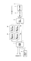
図1 に直交検波出力からの遅延プロファイル計算回路の構成を示す。I 成分相関値およびQ 成分相関値より電力化部4にて計算された電力遅延プロファイルは、電力レベル変動監視部5に入力され、電力レベル変動監視部5では同一電力加算処理に用いられる複数遅延プロファイル各サンプル点について電力レベル変動を監視する。正しい受信パスのタイミングには、高い相関値が安定して、すなわち受信レベル変動が小さく観測される。また、ノイズ等の影響により発生した瞬時的な高い相関値は、受信レベル変動が大きく観測される。この結果から重み付け係数制御部6では受信レベル変動が大きい相関値は電力加算時に受信レベルが小さくなるように係数を決定し、制御する。
【0013】
【発明の実施の形態】
以下、本発明の実施の形態について添付図面を参照しながら説明する。図1は本発明に係るパスサーチ回路の最良の実施の形態の構成図である。同図はパスサーチ回路中の遅延プロファイル計算回路の一例を示している。同図を参照すると遅延プロファイル計算回路は、相関値計算部1と、拡散信号生成部2と、同相加算部3と、電力化部4と、電力レベル変動監視部5と、重み付け係数制御部6と、電力加算部7と、制御部8と、記録媒体9とを含んで構成される。
【0014】
直交検波され、復調されたI成分信号およびQ成分信号は各々相関値計算部1に入力され、拡散信号生成部2にて生成された拡散信号と相関値計算が行われる。同相加算部3ではS/N比改善のため、I成分相関値およびQ成分相関値の同相加算が行われる。同相加算された相関値は電力化部4にて電力化され、遅延プロファイルが計算される。計算された遅延プロファイルはノイズフロアやフェージングによる変動平滑化のため、電力加算部7にて平均処理がなされ、平均遅延プロファイルが計算される。携帯端末はその平均遅延プロファイルを用いて受信パスタイミングを推定(パスサーチ)し、復調処理を行う。
【0015】
本発明では電力化部4から出力された遅延プロファイルが電力レベル変動監視部5に入力され、電力レベル変動監視部5にて同一電力加算処理に用いられる複数遅延プロファイルにおける各サンプルの変動レベルが監視される。その結果を用いて重み付け係数制御部6では、ノイズの影響による強電力レベルと推測されるサンプルについては、電力加算部7にて電力加算する際に、電力レベルが低くなるように重み付け係数が制御される。
【0016】
電力化部4の遅延プロファイルの出力周期が受信パス変動を無視できる短い周期の場合、受信パスタイミングによる遅延プロファイルレベルであれば、同一タイミングにおいて複数回連続して同等レベルで観測される。一方、受信パスタイミングではないノイズ等の影響により観測される電力の強い遅延プロファイルレベルは強レベル観測の連続性が無く、変動が激しく観測される。
【0017】
電力レベル変動監視部5では遅延プロファイル電力レベル変動が監視され、結果は重み付け係数制御部6に入力される。重み付け係数制御部6では電力加算部7の電力平均処理において、レベル変動が少ないサンプルタイミングに関してはそのまま加算処理が行われ、レベル変動が大きいサンプルタイミングに関しては電力加算処理において重み付けが行われ、平均後の電力レベルが単純加算よりも低く観測されるように制御される。
【0018】
制御部8は電力レベル変動監視部5および重み付け係数制御部6を制御する。記録媒体9には本発明に係るパスサーチ方法をコンピュータ(制御部8)に実行させるためのプログラムが格納されている。制御部8は記録媒体9に格納されたプログラムに従って電力レベル変動監視部5および重み付け係数制御部6を制御する。そのプログラムの内容については後述する。
【0019】
【実施例】
以下、本発明の実施例について説明する。なお、遅延プロファイル計算回路の構成は図1に示すものと同様であるため、図1を参照する。
【0020】
まず、第1実施例について説明する。直交検波が行われ、復調されたI成分信号およびQ成分信号は各々相関値計算部1に入力される。相関値計算部1では拡散信号生成部2にて生成された拡散信号と、入力されたI 成分信号、Q成分信号との相関計算を行う。CDMA方式では、受信されたI・Q成分信号と拡散信号生成部2にて生成された拡散信号に相関性が有るため、受信パスタイミングには高い相関値が計算される。相関結果は同相加算部3に入力され、同相加算部3では遅延プロファイルのS/N比改善のために、I成分およびQ成分相関値の同相加算が行われる。同相加算処理された相関値は電力化部4に入力され、電力計算されて遅延プロファイルとして出力される。
【0021】
電力レベル変動監視部5では同一電力加算処理に用いられる複数遅延プロファイル間の各サンプルタイミングにおける電力レベルの監視が行われ、電力閾値P_thを越えているサンプルは重み付け制御候補サンプルとして保持され、結果が重み付け係数制御部6に入力される。
【0022】
重み付け係数制御部6では入力された結果をもとに、同一サンプルタイミングにおける変動が変動閾値Lev_th未満か否かが判定され、Lev_th未満のサンプルタイミングに関しては変動が小さく、受信パスタイミングとして判断される。また、同一サンプルタイミングにおける変動がLev_th以上であれば受信パスタイミングによる強電力レベルが観測された訳ではなく、変動の大きいノイズ等の影響による瞬時的な強電力レベルの発生したサンプルタイミングだと判断され、電力加算部7にて複数の遅延プロファイルを用いて電力加算処理を行う際に、そのノイズの影響と判断したサンプルタイミングの電力レベルの影響を軽減するように重み付け係数W(<0)が決定される。
【0023】
電力加算部7ではノイズやフェージング変動の平滑化のために複数の遅延プロファイルを用いて電力加算処理が行われるが、重み付け係数制御部6にて決定された重み付け係数を用いて電力加算処理が行われるため、ノイズの影響により発生した瞬時的な強電力レベルの影響を軽減した平均遅延プロファイルの計算が可能である。
【0024】
重み付け係数Wの決定方法としては種々有り得る。第1の方法は重み付け係数Wを固定値とすることである。
【0025】
第2の方法は重み付け係数Wを遅延プロファイル最大電力レベルによって制御することである。たとえば、最大電力レベルがX0dBであれば重み付け係数はW0、X1dBであれば重み付け係数はW1とする。なお、最大電力レベルは過去の遅延プロファイルの最大電力レベルであることも有り得る。
【0026】
第3の方法は重み付け係数Wを電力レベル変動量によって制御することである。たとえば、電力レベル変動量がY0dBであれば重み付け係数はW0,Y1dBであれば重み付け係数はW1とする。
【0027】
また、変動閾値Lev_thとの比較方法としては、重み付け制御候補サンプルとして同一サンプルタイミングが2点保持されている場合には、2点間の電力レベル差とLev_thを比較して重み付け制御実施判定を行う。同一サンプルタイミングが3点以上保持されている場合には変動閾値Lev_thとの比較方法は以下に示すものが有り得る。
【0028】
第1の方法は重み付け制御候補サンプルの最大電力レベルと最小電力レベルとの差とLev_thとを比較することである。
【0029】
第2の方法は時間的に前後する遅延プロファイルのサンプル間でのレベル差とLev_thを比較することである。例えば、N番目、N+1番目、N+3番目の遅延プロファイルから同一サンプルタイミングが重み付け制御候補として保持され、各々の電力レベルをP_N,P_N1,P_N3とした場合、|P_N−P_N1|および|P_N1−P_N3|を計算しLev_thを比較する。どちらか一方、もしくは両方の結果がLev_th以上であれば重み付け制御を実施する。
【0030】
次に、図1 、図2を参照して電力レベル変動監視部5にて実現される電力レベル変動監視処理について説明する。図2(A )〜図2(E )は電力化部4出力の時間的に連続した遅延プロファイルを示す図であり、図1の電力加算部7における電力加算数は一例として3とする。受信パスタイミングのサンプル点(図2(A )〜(C )のSmp_ A参照)では拡散信号生成部2にて生成された拡散信号と直交検波出力の間で相関性が保たれるため、同一のタイミングで安定した強電力レベルが連続して観測される。
【0031】
しかし、移動体通信では伝搬路におけるノイズやフェージングの影響により、誤った強電力レベルが観測される場合が有る(図2(A )〜(C )のSmp_ B参照)。その場合、ノイズと拡散信号の間には相関性がないために安定した強電力レベルが連続して観測されることは少ない。
【0032】
電力レベル変動監視部5では入力された遅延プロファイルのサンプル点における電力レベル強度および変動を監視し、監視結果を重み付け係数制御部6に入力する。
【0033】
重み付け係数制御部6では、電力レベル変動の大きいサンプルタイミングに関しては正しい受信パスタイミングではないと判断し、電力加算処理後の平均遅延プロファイルへの影響を軽減するよう重み付け係数を決定する。
【0034】
それにより、通常の電力加算処理ではノイズにより瞬時的に発生したと考えられるP_B2(図2(B )参照)の電力レベルの影響が残る平均遅延プロファイル結果(図2(D )のSmp_ B参照)が電力加算部7にて出力されるが、本発明では図2 (E )のSmp_ Bに示すP_B2の影響を軽減した平均遅延プロファイルの作成が可能である。
【0035】
すなわち、本発明では電力レベル変動を監視することにより重み付け係数(W<1)を決定し、ノイズの影響と判断した図2(B )のP_B2を検出したSmp_Bのサンプルタイミングにおいては、電力加算処理にて
P_B1+W×P_B2+P_B3
として電力加算計算を行う。
【0036】
ノイズの影響のない遅延プロファイルからは、パスサーチ処理における受信パスタイミング誤検出を減少させることが可能であり、受信特性改善が実現できる。
【0037】
次に、図1、図3を参照して重み付け係数制御処理について説明する。図3は重み付け係数制御処理の手順を示すフローチャートである。電力加算部7における電力加算プロファイル数をAdd_N(N は正の整数)とする(ステップ31)。
【0038】
電力レベル変動監視部5において、電力化部4から入力された遅延プロファイルサンプル点の電力レベルが電力閾値P_thを越えているか否かの判定を行う(ステップ32)。P_thを越える電力レベルのサンプル点については重み付け制御候補サンプルとして、そのタイミングと電力レベルを保持する(ステップ33)。また、P_thを越えない場合はステップ34に進む。
【0039】
全サンプル点について上記判定を行う(ステップ34)。全サンプル点について上記判定が終了すると、次回の遅延プロファイルをチェックする(ステップ35,36)。
【0040】
同様の判定処理を電力加算プロファイル数であるAdd_N回繰り返す(ステップ32〜36)。
【0041】
電力加算対象全遅延プロファイルに対して電力閾値判定が終了すると、重み付け制御候補情報は電力レベル変動監視部5から重み付け係数制御部6に入力される。重み付け係数制御部6では重み付け制御候補サンプルの有無を判定し(ステップ37)、保持されたサンプル点が存在する場合、そのサンプルタイミングにて複数回検出されているか判定する(ステップ38)。一方、ステップ37にて保持されたサンプル点が存在しない場合は処理終了となる。
【0042】
ステップ38において同一タイミングでの複数回の検出がないサンプルタイミング、すなわち、電力加算プロファイル数Add_Nの遅延プロファイルにおいて、一度しか電力閾値P_thを越える強電力レベルが検出されなかったサンプルについては、受信パスタイミングではなく、ノイズの影響による瞬時的に観測された強電力レベルサンプルタイミングと判断して、電力加算時にそのサンプルタイミングの電力レベルの影響を軽減するように重み付け係数 W(<1)により制御を行う(ステップ40)。
【0043】
一方、ステップ38において同一サンプルタイミングで複数回検出されているサンプルが存在する場合、その複数サンプルの電力レベル変動が変動閾値Lev_th未満かを判定する(ステップ39)。
【0044】
ステップ39にてLev_th未満であれば、そのサンプルタイミングは変動の少ない強電力レベルが検出されるサンプルタイミング、すなわち受信パスタイミングとして判断して重み付け係数制御を実施しない。
【0045】
一方、ステップ39にて変動閾値Lev_th以上の電力レベル変動が観測された場合は、そのサンプルタイミングはノイズの影響による強電力レベルと判断し、重み付け係数Wにより制御を行う(ステップ40)。
【0046】
次に、第2実施例について説明する。本発明によるパスサーチ回路は電力化された遅延プロファイルレベルを監視することにより重み付け係数を制御してノイズの影響を低減しているが、レベル監視および重み付け係数制御を相関値計算処理後または同相加算処理後に実施しても、ノイズの影響を低減した遅延プロファイル作成が可能である。
【0047】
図4に相関値計算後にレベル監視および重み付け係数制御を実施する回路構成図を示す。図4を参照すると、相関値計算部1と同相加算部3との間に電力レベル変動監視部15および重み付け係数制御部16ならびに電力レベル変動監視部25および重み付け係数制御部26が挿入されている。なお、図1と同様の構成部分については同一番号を付し、その説明を省略する。
【0048】
電力化処理前で変動量監視を実施する場合、I成分相関値およびQ成分相関値について各々相関値レベル変動を監視する。その結果より重み付け係数を決定し、同相加算部3における同相加算処理時に重み付け制御を行い、ノイズの影響を低減した同相加算結果を得る。重み付け制御は電力化部4における電力化処理時に実施しても構わない。
【0049】
図5に同相加算処理後にレベル監視および重み付け係数制御を実施する回路構成図を示す。図5を参照すると、同相加算部3と電力化部4との間に電力レベル変動監視部35および重み付け係数制御部36ならびに電力レベル変動監視部45および重み付け係数制御部46が挿入されている。なお、図1と同様の構成部分については同一番号を付し、その説明を省略する。
【0050】
電力化処理前で変動量監視を実施する場合、I成分相関値およびQ成分相関値について各々相関値レベル変動を監視する。その結果より重み付け係数を決定し、電力化部4における電力化処理時に重み付け制御を行い、ノイズの影響を低減した同相加算結果を得る。
【0051】
また、強電力レベルを検出するための閾値の決め方は種々あり得るので、記述する。第1の方法はあらかじめ固定値を決めておくことである。第2の方法は過去の平均遅延プロファイルを利用してフィードバックされた最大電力レベルに基づいて決定することである。たとえば、最大電力レベル+xdBの値(xは負の値も取り得る)等である。第3の方法は同一遅延プロファイル中の最大電力レベルに基づいて決定することである。たとえば、最大電力レベル+xdBの値(xは負の値も取り得る)等である。
【0052】
次に、第3実施例について説明する。第3実施例はパスサーチ方法をコンピュータ(制御部8)に実行させるためのプログラムに関するものである。そのプログラムが図1の記録媒体9に格納されていることは既に述べた。そのプログラムの内容は図3にフローチャートで示されるものである。制御部8は記録媒体9に格納されたプログラムに従って電力レベル変動監視部5、15、25、35、45および重み付け係数制御部6、16、26、36、46を制御する。そのプログラムの内容については既に述べたのでここでの説明は省略する。
【0053】
【発明の効果】
以上説明したように本発明によれば、パスサーチ処理の遅延プロファイル計算において、同一電力加算処理に用いられる複数の遅延プロファイルにおける各サンプルのレベル変動を監視し、その監視結果に応じて所定サンプルの電力レベルに重み付けを行う構成を有するため、安定したパスをサーチすることが可能となる。
【0054】
すなわち、第1の効果は雑音による受信パスタイミング誤検出を低減し、良好な受信特性を得ることができることである。その理由は、遅延プロファイル電力レベルを監視し、遅延プロファイル電力加算処理において重み付け制御することにより、ノイズによる瞬時的強電力レベルの影響を低減した平均遅延プロファイル作成が可能だからである。
【0055】
第2 の効果は移動体通信におけるパス変動にも素早く追従し、良好な受信特性を得ることができることである。その理由は、ノイズの影響を軽減した遅延プロファイルを作成することにより、遅延プロファイル平均時間を削減し、パスサーチ処理の高速化が可能だからである。
【図面の簡単な説明】
【図1】本発明に係るパスサーチ回路の最良の実施の形態の構成図である。
【図2】電力化部4出力の時間的に連続した遅延プロファイルを示す図である。
【図3】重み付け係数制御処理の手順を示すフローチャートである。
【図4】相関値計算後にレベル監視および重み付け係数制御を実施する回路構成図である。
【図5】同相加算処理後にレベル監視および重み付け係数制御を実施する回路構成図である。
【符号の説明】
1 相関値計算部
2 拡散信号生成部
3 同相加算部
4 電力化部
5 電力レベル変動監視部
6 重み付け係数制御部
7 電力加算部
15 電力レベル変動監視部
16 重み付け係数制御部
25 電力レベル変動監視部
26 重み付け係数制御部
35 電力レベル変動監視部
36 重み付け係数制御部
45 電力レベル変動監視部
46 重み付け係数制御部[0001]
BACKGROUND OF THE INVENTION
The present invention relates to a path search circuit and method and program thereof, and more particularly to a path search circuit and method and program in a CDMA (Code Division Multiple Access) communication system.
[0002]
[Prior art]
Conventionally, a CDMA demodulation circuit obtains a path diversity effect by path search and rake combining. Radio waves received in a mobile communication environment are subject to level fluctuations due to multipath fading and quality degradation due to noise. In the case of severe path fluctuations, the frequency of path timing error detection in path search becomes high, and the reception characteristics deteriorate when path timing error detection occurs. Therefore, a path search process for searching for a stable path among the incoming paths and assigning it to a finger is desired.
[0003]
On the other hand, as an example of this type of prior art, it is determined whether or not to perform interpolation processing to reduce the chip interval before and after each processing unit for each of a plurality of processing units according to the number of communication channels to be processed. A path search apparatus that performs interpolation processing before and after each processing unit in the path search processing means based on the result is disclosed (for example, see Patent Document 1).
[0004]
[Patent Document 1]
Japanese Patent Laid-Open No. 2001-36430 (Claims, FIG. 1)
[0005]
[Problems to be solved by the invention]
This technique is intended to search for a stable path, and is common to the present invention in this respect. However, the means for achieving the objective is to control which process interpolates between interpolation processes. This is completely different from the present invention.
[0006]
Accordingly, an object of the present invention is to provide a path search circuit capable of searching for a stable path by means completely different from the technique described in Patent Document 1, a method thereof, and a program.
[0007]
[Means for Solving the Problems]
The path search circuit according to the present invention is a path search circuit in a CDMA communication system, and the circuit detects an instantaneous level of each sample in a plurality of delay profiles used in the same power addition process in the delay profile calculation of the path search process. monitoring the change, the monitoring result viewing including the weighting control means for weighting the power level of a predetermined sample according to the weighting control means holds the sample exceeding the power threshold as the weighting candidate, said weighting control means When there are a plurality of weighting candidate samples, a negative weighting is performed on the power levels of the plurality of samples when a power level difference between predetermined samples is equal to or greater than a variation threshold .
[0008]
In addition, the path search method according to the present invention is a path search method in a CDMA communication system, and in the delay profile calculation of the path search process, the method instantaneously calculates each sample in a plurality of delay profiles used for the same power addition process. monitors a level change, seen including a weighting controlling step for weighting the power level of a predetermined sample in accordance with the monitoring result, the weighting control step holds the sample exceeding the power threshold as the weighting candidate, the weighting control The step is characterized in that, when there are a plurality of weighting candidate samples, the power level of the plurality of samples is negatively weighted when a power level difference between predetermined samples is equal to or greater than a variation threshold .
[0009]
A program according to the present invention is a program for causing a computer to execute a path search method in a CDMA communication system, and the program includes a plurality of delay profiles used for the same power addition process in the delay profile calculation of the path search process. monitoring the instantaneous level variation for each sample in, look including the weighting control step of performing weighting to the power level of a predetermined sample in accordance with the monitoring result, the sample said weighting control means exceeding the power threshold as the weighting candidate And the weighting control means negatively weights the power levels of the plurality of samples when the power level difference between predetermined samples is equal to or greater than a variation threshold when there are a plurality of weighting candidate samples. .
[0010]
This makes it possible to search for a stable path.
[0011]
That is, the CDMA path search circuit according to the present invention can receive a stable path by adaptively controlling the delay profile averaging process according to the fluctuation of the correlation value level in the delay profile calculation of the path search process. This achieves a good reception characteristic.
[0012]
Figure 1 shows the configuration of the delay profile calculation circuit from the quadrature detection output. The power delay profile calculated by the power generation unit 4 from the I component correlation value and the Q component correlation value is input to the power level variation monitoring unit 5, and the power level variation monitoring unit 5 uses a plurality of delays used for the same power addition processing. Monitor power level variation for each sample point in the profile. At the correct reception path timing, a high correlation value is observed stably, that is, the reception level fluctuation is small. In addition, the reception level fluctuation is greatly observed in the instantaneous high correlation value generated by the influence of noise or the like. From this result, the weighting coefficient control unit 6 determines and controls the coefficient so that the correlation value with large reception level fluctuation becomes small when adding power.
[0013]
DETAILED DESCRIPTION OF THE INVENTION
Hereinafter, embodiments of the present invention will be described with reference to the accompanying drawings. FIG. 1 is a block diagram of the best embodiment of a path search circuit according to the present invention. This figure shows an example of a delay profile calculation circuit in the path search circuit. Referring to the figure, the delay profile calculation circuit includes a correlation value calculation unit 1, a spread signal generation unit 2, an in-
[0014]
The I component signal and the Q component signal subjected to quadrature detection and demodulated are respectively input to the correlation value calculation unit 1, and the spread signal generated by the spread signal generation unit 2 and the correlation value are calculated. In-
[0015]
In the present invention, the delay profile output from the power conversion unit 4 is input to the power level variation monitoring unit 5, and the power level variation monitoring unit 5 monitors the variation level of each sample in a plurality of delay profiles used for the same power addition processing. Is done. Using the result, the weighting coefficient control unit 6 controls the weighting coefficient so that the power level of the sample presumed to be a strong power level due to the noise is reduced when the
[0016]
When the output cycle of the delay profile of the power generation unit 4 is a short cycle in which the reception path fluctuation can be ignored, if the delay profile level is based on the reception path timing, the same level is observed at the same level continuously several times. On the other hand, the strong delay profile level observed due to the influence of noise or the like other than the reception path timing has no continuity of the strong level observation, and the fluctuation is observed severely.
[0017]
The power level fluctuation monitoring unit 5 monitors the delay profile power level fluctuation, and the result is input to the weighting coefficient control unit 6. In the power averaging process of the
[0018]
The control unit 8 controls the power level fluctuation monitoring unit 5 and the weighting coefficient control unit 6. The
[0019]
【Example】
Examples of the present invention will be described below. Since the configuration of the delay profile calculation circuit is the same as that shown in FIG. 1, reference is made to FIG.
[0020]
First, the first embodiment will be described. Quadrature detection is performed, and the demodulated I component signal and Q component signal are each input to the correlation value calculation unit 1. The correlation value calculation unit 1 calculates the correlation between the spread signal generated by the spread signal generation unit 2 and the input I component signal and Q component signal. In the CDMA system, since the received I / Q component signal and the spread signal generated by the spread signal generation unit 2 have a correlation, a high correlation value is calculated at the reception path timing. The correlation result is input to the in-
[0021]
The power level fluctuation monitoring unit 5 monitors the power level at each sample timing among a plurality of delay profiles used for the same power addition process, and a sample exceeding the power threshold P_th is held as a weighting control candidate sample, and the result is Input to the weighting coefficient control unit 6.
[0022]
Based on the input result, the weighting coefficient control unit 6 determines whether or not the variation at the same sample timing is less than the variation threshold Lev_th, and the sample timing less than Lev_th has a small variation and is determined as the reception path timing. . If the fluctuation at the same sample timing is equal to or higher than Lev_th, the strong power level due to the reception path timing is not observed, but it is determined that it is the sample timing at which the instantaneous strong power level is generated due to the influence of noise having a large fluctuation. When the
[0023]
The
[0024]
There are various methods for determining the weighting coefficient W. The first method is to set the weighting coefficient W to a fixed value.
[0025]
The second method is to control the weighting factor W by the delay profile maximum power level. For example, if the maximum power level is X0 dB, the weighting coefficient is W0, and if it is X1 dB, the weighting coefficient is W1. Note that the maximum power level may be the maximum power level of a past delay profile.
[0026]
The third method is to control the weighting coefficient W by the power level fluctuation amount. For example, if the power level fluctuation amount is Y0 dB, the weighting coefficient is W0, and if it is Y1 dB, the weighting coefficient is W1.
[0027]
Further, as a comparison method with the variation threshold value Lev_th, when two points of the same sample timing are held as the weighting control candidate samples, the power level difference between the two points is compared with the Lev_th and the weighting control execution determination is performed. . When the same sample timing is held at three or more points, the following comparison method with the variation threshold value Lev_th can be used.
[0028]
The first method is to compare the difference between the maximum power level and the minimum power level of the weighting control candidate samples with Lev_th.
[0029]
The second method is to compare the level difference between samples of the delay profile that moves back and forth in time and the Lev_th. For example, when the same sample timing is held as a weighting control candidate from the Nth, N + 1th, and N + 3th delay profiles and the respective power levels are P_N, P_N1, and P_N3, | P_N-P_N1 | and | P_N1-P_N3 | And Lev_th is compared. If either or both results are equal to or higher than Lev_th, weighting control is performed.
[0030]
Next, the power level fluctuation monitoring process realized by the power level fluctuation monitoring unit 5 will be described with reference to FIGS. 2 (A) to 2 (E) are diagrams showing a temporally continuous delay profile of the output of the power generation unit 4, and the power addition number in the
[0031]
However, in mobile communication, an erroneous strong power level may be observed due to the influence of noise or fading in the propagation path (see Smp_B in FIGS. 2A to 2C). In that case, since there is no correlation between the noise and the spread signal, a stable strong power level is rarely observed continuously.
[0032]
The power level fluctuation monitoring unit 5 monitors the power level intensity and fluctuation at the sample points of the input delay profile, and inputs the monitoring result to the weighting coefficient control unit 6.
[0033]
The weighting coefficient control unit 6 determines that the sample timing with a large power level fluctuation is not a correct reception path timing, and determines the weighting coefficient so as to reduce the influence on the average delay profile after the power addition process.
[0034]
As a result, the average delay profile result (see Smp_B in FIG. 2 (D)) remains affected by the power level of P_B2 (see FIG. 2 (B)), which is considered to have occurred instantaneously due to noise in normal power addition processing. Is output from the
[0035]
That is, in the present invention, a power addition process is performed at the sampling timing of Smp_B in which the weighting coefficient (W <1) is determined by monitoring the power level fluctuation and P_B2 in FIG. At P_B1 + W × P_B2 + P_B3
The power addition calculation is performed as follows.
[0036]
From a delay profile that is not affected by noise, it is possible to reduce reception path timing error detection in the path search process, and to improve reception characteristics.
[0037]
Next, the weighting coefficient control process will be described with reference to FIGS. FIG. 3 is a flowchart showing the procedure of the weighting coefficient control process. The number of power addition profiles in the
[0038]
In the power level fluctuation monitoring unit 5, it is determined whether or not the power level of the delay profile sample point input from the power generation unit 4 exceeds the power threshold P_th (step 32). For the sample point of the power level exceeding P_th, the timing and the power level are held as weighting control candidate samples (step 33). If P_th is not exceeded, the process proceeds to step 34.
[0039]
The above determination is made for all sample points (step 34). When the above determination is completed for all sample points, the next delay profile is checked (
[0040]
Similar determination processing is repeated Add_N times that is the number of power addition profiles (steps 32-36).
[0041]
When the power threshold determination is completed for the power addition target all delay profile, the weight control candidate information is input from the power level fluctuation monitoring unit 5 to the weighting coefficient control unit 6. The weighting coefficient control unit 6 determines the presence / absence of a weighting control candidate sample (step 37), and if there is a held sample point, determines whether it has been detected a plurality of times at that sample timing (step 38). On the other hand, if the sample point held in step 37 does not exist, the process ends.
[0042]
In step 38, sample timing at which detection is not performed a plurality of times at the same timing, that is, for samples in which a strong power level exceeding the power threshold P_th is detected only once in the delay profile of the power addition profile number Add_N, the reception path timing Instead, it is determined that the power level sample timing is instantaneously observed due to the influence of noise, and control is performed with the weighting factor W (<1) so as to reduce the influence of the power level of the sample timing when adding power. (Step 40).
[0043]
On the other hand, if there are samples detected multiple times at the same sample timing in step 38, it is determined whether the power level variation of the plurality of samples is less than the fluctuation threshold Lev_th (step 39).
[0044]
If it is less than Lev_th in step 39, the sample timing is determined as a sample timing at which a strong power level with little fluctuation is detected, that is, a reception path timing, and weighting coefficient control is not performed.
[0045]
On the other hand, if a power level fluctuation equal to or greater than the fluctuation threshold Lev_th is observed in step 39, the sample timing is determined to be a strong power level due to the influence of noise, and control is performed using the weighting coefficient W (step 40).
[0046]
Next, a second embodiment will be described. The path search circuit according to the present invention controls the weighting coefficient by monitoring the power-generated delay profile level to reduce the influence of noise. However, the level monitoring and the weighting coefficient control are performed after correlation value calculation processing or in-phase addition. Even if it is implemented after processing, it is possible to create a delay profile with reduced influence of noise.
[0047]
FIG. 4 shows a circuit configuration diagram for performing level monitoring and weighting coefficient control after the correlation value calculation. Referring to FIG. 4, the power level
[0048]
When the fluctuation amount is monitored before the power processing, the correlation value level fluctuation is monitored for each of the I component correlation value and the Q component correlation value. A weighting coefficient is determined based on the result, and weighting control is performed during the in-phase addition process in the in-
[0049]
FIG. 5 shows a circuit configuration diagram for performing level monitoring and weighting coefficient control after the in-phase addition processing. Referring to FIG. 5, a power level
[0050]
When the fluctuation amount is monitored before the power processing, the correlation value level fluctuation is monitored for each of the I component correlation value and the Q component correlation value. A weighting coefficient is determined from the result, weighting control is performed during the power processing in the power generating unit 4, and a result of in-phase addition in which the influence of noise is reduced is obtained.
[0051]
There are various ways of determining the threshold value for detecting the strong power level, which will be described. The first method is to determine a fixed value in advance. The second method is to make a determination based on the maximum power level fed back using a past average delay profile. For example, the value of the maximum power level + xdB (x may be a negative value). The third method is to determine based on the maximum power level in the same delay profile. For example, the value of the maximum power level + xdB (x may be a negative value).
[0052]
Next, a third embodiment will be described. The third embodiment relates to a program for causing a computer (control unit 8) to execute a path search method. As described above, the program is stored in the
[0053]
【The invention's effect】
As described above, according to the present invention, in the delay profile calculation of the path search process, the level variation of each sample in a plurality of delay profiles used for the same power addition process is monitored, and a predetermined sample is detected according to the monitoring result. Since the power level is weighted, a stable path can be searched.
[0054]
That is, the first effect is that false detection of reception path timing due to noise can be reduced and good reception characteristics can be obtained. The reason is that, by monitoring the delay profile power level and performing weighting control in the delay profile power addition process, it is possible to create an average delay profile in which the influence of the instantaneous strong power level due to noise is reduced.
[0055]
The second effect is that it can quickly follow path fluctuations in mobile communications and obtain good reception characteristics. The reason is that by creating a delay profile that reduces the influence of noise, the delay profile average time can be reduced and the speed of the path search process can be increased.
[Brief description of the drawings]
FIG. 1 is a configuration diagram of a preferred embodiment of a path search circuit according to the present invention.
FIG. 2 is a diagram showing a temporally continuous delay profile of the output of the power generation unit 4;
FIG. 3 is a flowchart illustrating a procedure of weighting coefficient control processing.
FIG. 4 is a circuit configuration diagram for performing level monitoring and weighting coefficient control after correlation value calculation.
FIG. 5 is a circuit configuration diagram for performing level monitoring and weighting coefficient control after in-phase addition processing;
[Explanation of symbols]
DESCRIPTION OF SYMBOLS 1 Correlation value calculation part 2 Spread
Claims (12)
パスサーチ処理の遅延プロファイル計算において、同一電力加算処理に用いられる複数の遅延プロファイルにおける各サンプルの瞬時的なレベル変動を監視し、その監視結果に応じて所定サンプルの電力レベルに重み付けを行う重み付け制御手段を含み、
前記重み付け制御手段は電力閾値を越えるサンプルを前記重み付け候補として保持し、
前記重み付け制御手段は前記重み付け候補のサンプルが複数の場合は所定サンプル間の電力レベル差が変動閾値以上の場合に前記複数のサンプルの電力レベルに負の重み付けを行うことを特徴とするパスサーチ回路。A path search circuit in a CDMA communication system, comprising:
In delay profile calculation of path search processing, weighting control that monitors instantaneous level fluctuation of each sample in a plurality of delay profiles used for the same power addition processing and weights the power level of a predetermined sample according to the monitoring result means only including,
The weight control means holds a sample exceeding a power threshold as the weight candidate,
The weighting control means, when there are a plurality of weighting candidate samples, performs a negative weighting on the power levels of the plurality of samples when a power level difference between predetermined samples is not less than a variation threshold. .
パスサーチ処理の遅延プロファイル計算において、同一電力加算処理に用いられる複数の遅延プロファイルにおける各サンプルの瞬時的なレベル変動を監視し、その監視結果に応じて所定サンプルの電力レベルに重み付けを行う重み付け制御ステップを含み、
前記重み付け制御ステップは電力閾値を越えるサンプルを前記重み付け候補として保持し、
前記重み付け制御ステップは前記重み付け候補のサンプルが複数の場合は所定サンプル間の電力レベル差が変動閾値以上の場合に前記複数のサンプルの電力レベルに負の重み付けを行うことを特徴とするパスサーチ方法。A path search method in a CDMA communication system, comprising:
In delay profile calculation of path search processing, weighting control that monitors instantaneous level fluctuation of each sample in a plurality of delay profiles used for the same power addition processing and weights the power level of a predetermined sample according to the monitoring result step only contains,
The weighting control step holds samples that exceed a power threshold as the weighting candidates,
The weighting control step, when there are a plurality of weighting candidate samples, performs a negative weighting on the power levels of the plurality of samples when a power level difference between predetermined samples is equal to or greater than a variation threshold. .
パスサーチ処理の遅延プロファイル計算において、同一電力加算処理に用いられる複数の遅延プロファイルにおける各サンプルの瞬時的なレベル変動を監視し、その監視結果に応じて所定サンプルの電力レベルに重み付けを行う重み付け制御ステップを含み、
前記重み付け制御ステップは電力閾値を越えるサンプルを前記重み付け候補として保持し、
前記重み付け制御ステップは前記重み付け候補のサンプルが複数の場合は所定サンプル間の電力レベル差が変動閾値以上の場合に前記複数のサンプルの電力レベルに負の重み付けを行うことを特徴とするプログラム。A program for causing a computer to execute a path search method in a CDMA communication system,
In delay profile calculation of path search processing, weighting control that monitors instantaneous level fluctuation of each sample in a plurality of delay profiles used for the same power addition processing and weights the power level of a predetermined sample according to the monitoring result step only contains,
The weighting control step holds samples that exceed a power threshold as the weighting candidates,
In the weighting control step, when there are a plurality of weighting candidate samples, a negative weighting is performed on the power levels of the plurality of samples when a power level difference between predetermined samples is equal to or greater than a variation threshold .
Priority Applications (5)
| Application Number | Priority Date | Filing Date | Title |
|---|---|---|---|
| JP2003019604A JP4165238B2 (en) | 2003-01-29 | 2003-01-29 | Path search circuit, method and program |
| US10/765,124 US7804810B2 (en) | 2003-01-29 | 2004-01-28 | Circuit, method, and program in a CDMA communication system for quickly tracking a stable path |
| DE200460007834 DE602004007834T2 (en) | 2003-01-29 | 2004-01-29 | Pathfinding method, apparatus and program |
| EP20040001943 EP1443672B1 (en) | 2003-01-29 | 2004-01-29 | Path searching circuit, method and program in a CDMA communication system |
| CNB2004100074124A CN1277362C (en) | 2003-01-29 | 2004-01-29 | Route searching circuit and route searching method |
Applications Claiming Priority (1)
| Application Number | Priority Date | Filing Date | Title |
|---|---|---|---|
| JP2003019604A JP4165238B2 (en) | 2003-01-29 | 2003-01-29 | Path search circuit, method and program |
Publications (2)
| Publication Number | Publication Date |
|---|---|
| JP2004235777A JP2004235777A (en) | 2004-08-19 |
| JP4165238B2 true JP4165238B2 (en) | 2008-10-15 |
Family
ID=32652858
Family Applications (1)
| Application Number | Title | Priority Date | Filing Date |
|---|---|---|---|
| JP2003019604A Expired - Fee Related JP4165238B2 (en) | 2003-01-29 | 2003-01-29 | Path search circuit, method and program |
Country Status (5)
| Country | Link |
|---|---|
| US (1) | US7804810B2 (en) |
| EP (1) | EP1443672B1 (en) |
| JP (1) | JP4165238B2 (en) |
| CN (1) | CN1277362C (en) |
| DE (1) | DE602004007834T2 (en) |
Families Citing this family (8)
| Publication number | Priority date | Publication date | Assignee | Title |
|---|---|---|---|---|
| US20060067383A1 (en) * | 2004-09-29 | 2006-03-30 | Carmela Cozzo | Parameter estimate initialization using interpolation |
| CN1707989B (en) * | 2005-05-13 | 2010-12-22 | 上海宣普实业有限公司 | Method for timing tracking path search in CDMA system |
| JP4728772B2 (en) * | 2005-10-26 | 2011-07-20 | 日本電気株式会社 | Delay profile generation circuit and method thereof, and receiver and program |
| US8014478B2 (en) * | 2007-12-26 | 2011-09-06 | Broadcom Corporation | Method and apparatus for impulse noise detection and suppression for DVB-T |
| US20110026430A1 (en) * | 2009-07-30 | 2011-02-03 | Qualcomm Incorporated | Method and apparatus for detecting a channel condition for a wireless communication device |
| US9094083B2 (en) * | 2010-05-18 | 2015-07-28 | Qualcomm Incorporated | Systems, apparatus and methods to facilitate efficient repeater usage |
| JP5896795B2 (en) * | 2012-03-14 | 2016-03-30 | 三菱電機株式会社 | Equalizer, receiver, and equalization method |
| JP5897207B2 (en) | 2013-04-10 | 2016-03-30 | 三菱電機株式会社 | Receiving apparatus and receiving method |
Family Cites Families (35)
| Publication number | Priority date | Publication date | Assignee | Title |
|---|---|---|---|---|
| JP2934185B2 (en) * | 1996-03-15 | 1999-08-16 | 松下電器産業株式会社 | CDMA cellular radio base station apparatus, mobile station apparatus, and transmission method |
| US6026115A (en) * | 1996-08-23 | 2000-02-15 | Ntt Mobile Communications Network, Inc. | Rake receiver |
| JP2924864B2 (en) * | 1997-06-16 | 1999-07-26 | 日本電気株式会社 | Adaptive rake reception method |
| US6731711B1 (en) * | 1997-11-19 | 2004-05-04 | Lg Electronics Inc. | Signal recovery system |
| DE19824218C1 (en) | 1998-05-29 | 2000-03-23 | Ericsson Telefon Ab L M | Multipath propagation delay determining device using periodically inserted pilot symbols |
| JP3092798B2 (en) * | 1998-06-30 | 2000-09-25 | 日本電気株式会社 | Adaptive transceiver |
| CN1192651C (en) * | 1998-07-16 | 2005-03-09 | 三星电子株式会社 | Processing packet data in mobile communication system |
| JP3031354B1 (en) | 1998-09-30 | 2000-04-10 | 日本電気株式会社 | CDMA receiver, multipath finger assignment method thereof, and recording medium recording control program therefor |
| JP3554207B2 (en) * | 1998-11-10 | 2004-08-18 | 松下電器産業株式会社 | Wireless communication device and wireless communication method |
| US6269239B1 (en) * | 1998-12-11 | 2001-07-31 | Nortel Networks Corporation | System and method to combine power control commands during soft handoff in DS/CDMA cellular systems |
| JP3641961B2 (en) * | 1999-02-01 | 2005-04-27 | 株式会社日立製作所 | Wireless communication device using adaptive array antenna |
| JP3149868B2 (en) * | 1999-02-24 | 2001-03-26 | 日本電気株式会社 | Receiving path search method and searcher circuit for CDMA receiver |
| JP2000252955A (en) | 1999-03-02 | 2000-09-14 | Sanyo Electric Co Ltd | Reception equipment and reception method |
| JP3930187B2 (en) * | 1999-03-03 | 2007-06-13 | 株式会社日立コミュニケーションテクノロジー | Synchronization control method, receiver, base station, and mobile terminal |
| JP3322246B2 (en) | 1999-07-21 | 2002-09-09 | 日本電気株式会社 | Path search apparatus and method |
| US6996080B1 (en) * | 1999-07-23 | 2006-02-07 | Itt Manufacturing Enterprises, Inc. | Chip-synchronous CDMA multiplexer and method resulting in constant envelope signals |
| KR20010038528A (en) * | 1999-10-26 | 2001-05-15 | 조정남 | Apparatus and method for controlling a power of reverse link in CDMA system |
| KR100467543B1 (en) * | 1999-12-28 | 2005-01-24 | 엔티티 도꼬모 인코퍼레이티드 | Path search method, channel estimation method, and communication systems |
| JP2001203620A (en) * | 2000-01-19 | 2001-07-27 | Matsushita Electric Ind Co Ltd | Wireless base station device and wireless communication method |
| WO2001067627A1 (en) * | 2000-03-06 | 2001-09-13 | Fujitsu Limited | Cdma receiver and searcher of the cdma receiver |
| JP2001308744A (en) * | 2000-04-19 | 2001-11-02 | Nec Corp | Mobile communications demodulator, its demodulation method, and recording medium recorded with its control program |
| JP3501783B2 (en) * | 2000-08-23 | 2004-03-02 | 日本電気株式会社 | CDMA receiving apparatus and CDMA receiving method |
| JP3497480B2 (en) * | 2000-09-04 | 2004-02-16 | 松下電器産業株式会社 | Phase rotation detection device and radio base station device provided with the same |
| JP2002198875A (en) * | 2000-12-22 | 2002-07-12 | Nippon Soken Inc | Communication terminal of cdma system |
| JP4081982B2 (en) | 2001-01-30 | 2008-04-30 | 日本電気株式会社 | CDMA mobile communication demodulation circuit and demodulation method |
| JP3551254B2 (en) | 2001-02-05 | 2004-08-04 | 日本電気株式会社 | Path detecting method, path detecting apparatus, and array antenna receiving apparatus |
| JP3676986B2 (en) * | 2001-03-29 | 2005-07-27 | 松下電器産業株式会社 | Radio receiving apparatus and radio receiving method |
| JP3558053B2 (en) * | 2001-06-06 | 2004-08-25 | 日本電気株式会社 | Adaptive antenna receiver |
| GB2384660B (en) * | 2002-01-25 | 2004-11-17 | Toshiba Res Europ Ltd | Reciever processing systems |
| US6748009B2 (en) * | 2002-02-12 | 2004-06-08 | Interdigital Technology Corporation | Receiver for wireless telecommunication stations and method |
| US6748013B2 (en) * | 2002-02-12 | 2004-06-08 | Interdigital Technology Corporation | Receiver for wireless telecommunication stations and method |
| WO2004025859A1 (en) * | 2002-09-13 | 2004-03-25 | Telefonaktiebolaget Lm Ericsson (Publ) | Method for path-seacher scheduling |
| US20040072553A1 (en) * | 2002-09-20 | 2004-04-15 | Xiaohui Wang | Methods, systems, and computer program products for selecting delay positions for a RAKE receiver by adjusting the delay positions based on comparisons of signal to interference ratios and/or powers for multi-path signals over time |
| JP3969275B2 (en) | 2002-10-15 | 2007-09-05 | 株式会社日立製作所 | Wireless position measuring method and apparatus |
| US7277474B2 (en) * | 2002-11-05 | 2007-10-02 | Analog Devices, Inc. | Finger allocation for a path searcher in a multipath receiver |
-
2003
- 2003-01-29 JP JP2003019604A patent/JP4165238B2/en not_active Expired - Fee Related
-
2004
- 2004-01-28 US US10/765,124 patent/US7804810B2/en not_active Expired - Fee Related
- 2004-01-29 DE DE200460007834 patent/DE602004007834T2/en not_active Expired - Lifetime
- 2004-01-29 CN CNB2004100074124A patent/CN1277362C/en not_active Expired - Fee Related
- 2004-01-29 EP EP20040001943 patent/EP1443672B1/en not_active Expired - Fee Related
Also Published As
| Publication number | Publication date |
|---|---|
| JP2004235777A (en) | 2004-08-19 |
| EP1443672A3 (en) | 2005-01-05 |
| US20040184411A1 (en) | 2004-09-23 |
| CN1520079A (en) | 2004-08-11 |
| EP1443672A2 (en) | 2004-08-04 |
| EP1443672B1 (en) | 2007-08-01 |
| DE602004007834D1 (en) | 2007-09-13 |
| DE602004007834T2 (en) | 2008-04-10 |
| CN1277362C (en) | 2006-09-27 |
| US7804810B2 (en) | 2010-09-28 |
Similar Documents
| Publication | Publication Date | Title |
|---|---|---|
| JP2002520982A (en) | Adaptive setting method of path selection threshold for DS-CDMA receiver | |
| JPH118606A (en) | Adaptive rake reception system | |
| JP2005072927A (en) | Cdma receiving device, cdma receiving method, cdma receiving program, and program recording medium | |
| JP4165238B2 (en) | Path search circuit, method and program | |
| JP5231762B2 (en) | Receiver and reception processing method | |
| JP4022810B2 (en) | Array antenna wireless communication device and receiving device | |
| JP2007060183A (en) | Synchronous control apparatus and method thereof | |
| JP4818568B2 (en) | Composite reception method and composite reception apparatus | |
| EP1489757B1 (en) | Radio reception device, array parameter optimal value estimation method, and array parameter optimal value estimation program | |
| JP4081982B2 (en) | CDMA mobile communication demodulation circuit and demodulation method | |
| US7269437B2 (en) | Transmission power control circuit using W-CDMA method | |
| JP2003283378A (en) | Device and method for synchronization judgment | |
| JP2003008552A (en) | Antenna verification method and antenna verification processing apparatus | |
| EP1883166A1 (en) | Path search processing circuit, path search method and control program | |
| JP4336796B2 (en) | Path search method and path search circuit | |
| JP4052976B2 (en) | Path search apparatus and control method | |
| US20020061053A1 (en) | Apparatus and method of circular group-wise parallel interference cancellation for multi-rate DS-CDMA system | |
| JP2001274724A (en) | Delay profile measurement method and delay profile measurement circuit | |
| JP3571978B2 (en) | Path selection device, reception device, and path selection method | |
| JP3210914B2 (en) | Error estimation apparatus for direct-sequence received data and direct-sequence reception apparatus | |
| JP4728772B2 (en) | Delay profile generation circuit and method thereof, and receiver and program | |
| JP2007129549A (en) | Equalizer and equalizing method | |
| JP2001274726A (en) | Spread spectrum receiver and spread spectrum reception method | |
| JP2002300098A (en) | Synthesis diversity receiver | |
| JPH10233720A (en) | Diversity receiver |
Legal Events
| Date | Code | Title | Description |
|---|---|---|---|
| A621 | Written request for application examination |
Free format text: JAPANESE INTERMEDIATE CODE: A621 Effective date: 20051213 |
|
| A977 | Report on retrieval |
Free format text: JAPANESE INTERMEDIATE CODE: A971007 Effective date: 20071016 |
|
| A131 | Notification of reasons for refusal |
Free format text: JAPANESE INTERMEDIATE CODE: A131 Effective date: 20071023 |
|
| A521 | Written amendment |
Free format text: JAPANESE INTERMEDIATE CODE: A523 Effective date: 20071203 |
|
| A02 | Decision of refusal |
Free format text: JAPANESE INTERMEDIATE CODE: A02 Effective date: 20080408 |
|
| RD01 | Notification of change of attorney |
Free format text: JAPANESE INTERMEDIATE CODE: A7421 Effective date: 20080508 |
|
| A521 | Written amendment |
Free format text: JAPANESE INTERMEDIATE CODE: A523 Effective date: 20080529 |
|
| A521 | Written amendment |
Free format text: JAPANESE INTERMEDIATE CODE: A821 Effective date: 20080508 |
|
| RD01 | Notification of change of attorney |
Free format text: JAPANESE INTERMEDIATE CODE: A7421 Effective date: 20080604 |
|
| A911 | Transfer of reconsideration by examiner before appeal (zenchi) |
Free format text: JAPANESE INTERMEDIATE CODE: A911 Effective date: 20080618 |
|
| TRDD | Decision of grant or rejection written | ||
| A01 | Written decision to grant a patent or to grant a registration (utility model) |
Free format text: JAPANESE INTERMEDIATE CODE: A01 Effective date: 20080708 |
|
| A01 | Written decision to grant a patent or to grant a registration (utility model) |
Free format text: JAPANESE INTERMEDIATE CODE: A01 |
|
| A61 | First payment of annual fees (during grant procedure) |
Free format text: JAPANESE INTERMEDIATE CODE: A61 Effective date: 20080721 |
|
| R150 | Certificate of patent or registration of utility model |
Free format text: JAPANESE INTERMEDIATE CODE: R150 |
|
| FPAY | Renewal fee payment (event date is renewal date of database) |
Free format text: PAYMENT UNTIL: 20110808 Year of fee payment: 3 |
|
| FPAY | Renewal fee payment (event date is renewal date of database) |
Free format text: PAYMENT UNTIL: 20110808 Year of fee payment: 3 |
|
| FPAY | Renewal fee payment (event date is renewal date of database) |
Free format text: PAYMENT UNTIL: 20120808 Year of fee payment: 4 |
|
| FPAY | Renewal fee payment (event date is renewal date of database) |
Free format text: PAYMENT UNTIL: 20130808 Year of fee payment: 5 |
|
| LAPS | Cancellation because of no payment of annual fees |