JP4164293B2 - Developing device, process cartridge, and image forming apparatus - Google Patents
Developing device, process cartridge, and image forming apparatus Download PDFInfo
- Publication number
- JP4164293B2 JP4164293B2 JP2002161808A JP2002161808A JP4164293B2 JP 4164293 B2 JP4164293 B2 JP 4164293B2 JP 2002161808 A JP2002161808 A JP 2002161808A JP 2002161808 A JP2002161808 A JP 2002161808A JP 4164293 B2 JP4164293 B2 JP 4164293B2
- Authority
- JP
- Japan
- Prior art keywords
- developing roller
- developing
- process cartridge
- roller
- axial direction
- Prior art date
- Legal status (The legal status is an assumption and is not a legal conclusion. Google has not performed a legal analysis and makes no representation as to the accuracy of the status listed.)
- Expired - Fee Related
Links
Images


Classifications
-
- G—PHYSICS
- G03—PHOTOGRAPHY; CINEMATOGRAPHY; ANALOGOUS TECHNIQUES USING WAVES OTHER THAN OPTICAL WAVES; ELECTROGRAPHY; HOLOGRAPHY
- G03G—ELECTROGRAPHY; ELECTROPHOTOGRAPHY; MAGNETOGRAPHY
- G03G15/00—Apparatus for electrographic processes using a charge pattern
- G03G15/06—Apparatus for electrographic processes using a charge pattern for developing
- G03G15/08—Apparatus for electrographic processes using a charge pattern for developing using a solid developer, e.g. powder developer
- G03G15/0896—Arrangements or disposition of the complete developer unit or parts thereof not provided for by groups G03G15/08 - G03G15/0894
-
- G—PHYSICS
- G03—PHOTOGRAPHY; CINEMATOGRAPHY; ANALOGOUS TECHNIQUES USING WAVES OTHER THAN OPTICAL WAVES; ELECTROGRAPHY; HOLOGRAPHY
- G03G—ELECTROGRAPHY; ELECTROPHOTOGRAPHY; MAGNETOGRAPHY
- G03G2215/00—Apparatus for electrophotographic processes
- G03G2215/06—Developing structures, details
- G03G2215/0634—Developing device
Description
【0001】
【発明の属する技術分野】
本発明は、電子写真方式を採用した複写機やプリンタ等に使用される現像装置、現像カートリッジ,プロセスカートリッジ及びこれを用いた画像形成装置に関するものである。
【0002】
【従来の技術】
従来、電子写真画像形成プロセスを用いた画像形成装置においては、像担持体及びこれに作用するプロセス手段を一体的にカートリッジ化して、画像形成装置本体に着脱可能とするプロセスカートリッジ方式が採用されている。このプロセスカートリッジ方式によれば、装置のメンテナンスをサービスマンによらずにユーザー自身で行うことができ、格段に操作性を向上させることができる。そこでこのプロセスカートリッジ方式は、画像形成装置において広く採用されるに至っている。
【0003】
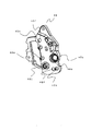
図17はこのようなカートリッジ方式を採用した画像形成装置の一例であり、複数のプロセスカートリッジを一列に並べたインライン型のカラープリンタ200である。画像形成装置に使用されるプロセスカートリッジ207の現像手段としては、一般的に現像剤担持体としての現像ローラ240を像担持体としての感光体ドラム201に対して接触状態で現像を行う接触現像方式、および現像ローラを感光体ドラムに対して所定の間隙を設けた状態で現像を行う非接触現像方式の2つの構成が知られている。
【0004】
プロセスカートリッジの現像装置の一例として、図18に示すような現像装置が提案、実用化されている。図18に示す従来の現像装置207においては、非磁性一成分のトナーを収容した現像容器245に、現像剤担持体としての現像ローラ240、現像剤規制部材としての現像ブレード244、および現像剤塗布部材としての塗布ローラ243が設けられている。現像ローラ240に供給されたトナーは現像ローラ240の回転に伴い現像ブレード244との当接部に送られる。ここで現像ブレード244により現像ローラ240上のトナーは均一な薄層(トナーコート)となる。
【0005】
現像ローラ240には現像バイアスが印加されており、感光体ドラム201上に形成された静電潜像に対応して現像ローラ240上のトナーが移動し、感光体ドラム201上にトナー像として顕像化される。
【0006】
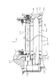
図19はプロセスカートリッジの長手方向断面図を示している。ここでは、現像ローラ240中心を軸とした断面で表している。
【0007】
図19に示すように現像ローラ240は、現像容器の両端に取り付けられている保持部材247および248の軸受部247aおよび248aに回動自在に取り付けられている。ここで、現像ローラ240の一方の端部には現像ローラ240の長手方向への移動量を規制するための規制部240cが設けられている。また反対側の端面には現像ローラを駆動するための駆動伝達部材としてのはす歯ギア279が取り付けられている。はす歯ギア279のねじれ方向は現像ローラ240に駆動がかかったときに発生するスラスト力で現像ローラ240を図中矢印Cの方向に移動させるようになっている。
【0008】
したがって、現像ローラ240に駆動がかかっている状態において現像ローラ240は、はす歯ギア279のスラスト力と、規制部240cによって常に一定の位置にあり、現像ローラ240がスラスト方向(図中y方向)に揺動することによる画像不良(多色を重ね合わせるときに生じる、いわゆる色ずれ)を防ぐことができる。
【0009】
【発明が解決しようとする課題】
しかしながら、従来の構成にあっては、環境変動による現像容器等の伸縮や、個々の部品の公差を吸収するため、現像ローラ240のスラスト方向にはガタを設けることが必要である。したがって、現像ローラ240に駆動がかかっていない時には、現像ローラ240は現像容器245および現像ブレード244に対してスラスト方向に移動可能な状態となっている。
【0010】
ここで、プロセスカートリッジの輸送時には様々な方向に振動が掛かることが予想されるが、現像ローラ長手方向に振動が掛かった場合、プロセスカートリッジ207の中で、現像ローラ240がスラスト方向に振動することがある。このとき現像ローラ240と現像ブレード244との間で摺擦が起こり、現像ローラ240にその履歴が残ってしまい、初期画像不良を引き起こす可能性がある。
【0011】
また一方で、現像ローラ240へバイアスを供給している接点276と現像ローラ240の位置関係も一定とはならない。現像ローラ240に駆動がかかると、はす歯ギア279の噛み合いで発生するスラスト力により現像ローラ240は規制位置に移動していくが、現像ローラ240に駆動がかかった直後の接点圧は一定ではなく、画像へ影響を与える可能性がある。
【0012】
本発明の目的は、各部品の公差を吸収し、かつ現像ローラのスラスト方向位置を常に一定とすることで画像不良を防止する構成を提供するとともに、組み立てが容易な構成とした、現像装置及び現像カートリッジ及びプロセスカートリッジ及び画像形成装置を提供することにある。
【0014】
【課題を解決するための手段】
上記目的を達成するために本発明のプロセスカートリッジにあっては、
画像形成装置本体に着脱可能なプロセスカートリッジにおいて、
電子写真感光体と、
現像容器と、
前記電子写真感光体に接触して前記電子写真感光体に形成された潜像を現像する、弾性体のローラ部と芯金部とを有する現像ローラであって、前記現像容器の両側面に設けられた保持部材によって前記芯金部を回転可能に支持され、前記現像ローラの軸線方向において一端側の前記保持部材との間にガタを有して取り付けられた現像ローラと、
前記現像ローラに担持されるトナーの厚さを規制する現像ブレードであって、前記現像容器に固定された、前記ローラ部と接触する現像ブレードと、
前記現像ローラの軸線方向の一端側に設けられた、前記現像ローラに駆動力を伝達し回転させるためのハス歯ギアであって、前記駆動力を受けた際に前記軸線方向において前記プロセスカートリッジの他端側に設けられた規制部に前記芯金部を当接させて、前記現像ローラの前記軸線方向における位置決めを行うスラスト力が生じるハス歯ギアと、
前記軸線方向において前記プロセスカートリッジの一端側に設けられた付勢手段であって、前記スラスト力が働く方向と同じ方向に前記現像ローラを付勢し、前記軸線方向において前記規制部に前記芯金部を当接させて、前記現像ローラに前記駆動力が伝達されていない場合でも前記現像ローラの前記軸線方向における位置決めを行う付勢手段と、
を有することを特徴とする。
【0017】
また、本発明の画像形成装置にあっては、
記録媒体に画像を形成する画像形成装置において、
(i)装着部と、
(ii)前記装着部に取り外し可能に装着されたプロセスカートリッジであって、
電子写真感光体と、
現像容器と、
前記電子写真感光体に接触して前記電子写真感光体に形成された潜像を現像する、弾性体のローラ部と芯金部とを有する現像ローラであって、前記現像容器の両側面に設けられた保持部材によって前記芯金部を回転可能に支持され、前記現像ローラの軸線方向において一端側の前記保持部材との間にガタを有して取り付けられた現像ローラと、
前記現像ローラに担持されるトナーの厚さを規制する現像ブレードであって、前記現像容器に固定された、前記ローラ部と接触する現像ブレードと、
前記現像ローラの軸線方向の一端側に設けられた、前記現像ローラに駆動力を伝達し回転させるためのハス歯ギアであって、前記駆動力を受けた際に前記軸線方向において前記プロセスカートリッジの他端側に設けられた規制部に前記芯金部を当接させて、前記現像ローラの前記軸線方向における位置決めを行うスラスト力が生じるハス歯ギアと、
前記軸線方向において前記プロセスカートリッジの一端側に設けられた付勢手段であって、前記スラスト力が働く方向と同じ方向に前記現像ローラを付勢し、前記軸線方向において前記規制部に前記芯金部を当接させて、前記現像ローラに前記駆動力が伝達されてい
ない場合でも前記現像ローラの前記軸線方向における位置決めを行う付勢手段と、
を有するプロセスカートリッジと、
(iii)前記記録媒体を搬送するための搬送手段と、
を有することを特徴とする。
【0026】
【発明の実施の形態】
以下に図面を参照して、この発明の好適な実施の形態を例示的に詳しく説明する。ただし、この実施の形態に記載されている構成部品の寸法、材質、形状、その相対配置などは、特に特定的な記載がない限りは、この発明の範囲をそれらのみに限定する趣旨のものではない。
【0027】
(第1の実施の形態)
図1〜図11を参照して、本発明の第1の実施の形態に係る現像装置及び現像カートリッジ及びプロセスカートリッジ及び画像形成装置について説明する。
【0028】
(画像形成装置の全体構成)
まず、画像形成装置の全体構成について、図2を参照して概要説明する。図2に示す画像形成装置100は、垂直方向に並設された像担持体である4個の感光体ドラム1a〜dを備えている。感光体ドラム1は、駆動手段(不図示)によって、同図中、反時計回りに回転駆動される。
【0029】
感光体ドラム1の周囲には、その回転方向に従って順に、感光体ドラム1表面を均一に帯電する帯電装置2a〜d、画像情報に基づいてレーザービームを照射し感光体ドラム1上の静電潜像を形成するスキャナユニット3a〜d、静電潜像に現像剤であるトナーを付着させてトナー像として現像する現像ユニット4a〜d、感光体ドラム1上のトナー像を転写材Sに転写させる静電転写装置5、転写後の感光体ドラム1表面に残った転写残トナーを除去するクリーニング装置60a〜d等が配設されている。
【0030】
ここで、感光体ドラム1と帯電装置2、現像ユニット4、クリーニング装置60は一体的にカートリッジ化されプロセスカートリッジ7を形成している。
【0031】
感光体ドラム1は、例えば直径30mmのアルミシリンダの外周面に有機光導伝体層(OPC感光体)を塗布して構成したものである。感光体ドラム1は、その両端部を支持部材によって回転自在に支持されており、一方の端部に不図示の駆動モータからの駆動力が伝達されることにより、反時計周りに回転駆動される。
【0032】
帯電装置2としては、図3に示すような接触帯電方式のものを使用することができる。本実施の形態において、帯電装置2は導電性ローラであり、このローラを感光体ドラム1表面に当接させるとともに、このローラに帯電バイアス電圧を印加することにより、感光体ドラム1表面を一様に帯電させるものである。
【0033】
スキャナユニット3は、感光体ドラム1の略水平方向に配置され、レーザーダイオード(不図示)によって画像信号に対応する画像光が、スキャナモーター(不図示)によって高速回転されるポリゴンミラー9a〜dに照射される。ポリゴンミラー9に反射した画像光は、結像レンズ10a〜dを介して帯電済みの感光体ドラム1表面を選択的に露光して静電潜像を形成するように構成している。
【0034】
またスキャナユニット3は、図5に示すように長手方向において左右側板間ピッチより長く形成され、左右側板32の開口穴35a〜35hから突起部33が外側に飛び出すように取り付けられる。その際のスキャナユニットの押圧方法は、図6に示すように、圧縮バネ36によって矢印で示す約45°下方に約9.8Nの力で押圧されている。これにより確実に突き当てに押し付け、位置決めがされている。
【0035】
図3に示すように、現像ユニット4はそれぞれイエロー、マゼンタ、シアン、ブラックの各色のトナーを夫々収納したトナー容器41a〜dおよび現像枠体45から構成され、トナー容器41内のトナー搬送機構42によってトナー供給ローラ43へ送り込み、図示時計方向に回転するトナー供給ローラ43および現像ローラ40の外周に圧接された現像ブレード44によって図示時計方向に回転する現像ローラ40の外周にトナーを塗布し、且つトナーに電荷を付与する。
【0036】
そして、潜像が形成された感光体ドラム1と対向した現像ローラ40に現像バイアスを印加することにより、潜像に応じて感光体ドラム1上にトナー現像を行うものである(詳細は後述する)。
【0037】
一方、画像形成装置には図2に示すように、すべての感光体ドラム1a〜dに対向し、接するように循環移動する静電転写ベルト11が配設される。静電転写ベルト11は1011〜1014Ω・cmの体積固有抵抗を持たせた厚さ約150μmのフィルム状部材で構成される。この静電転写ベルト11は、垂直方向に4軸でローラに支持され、図中左側の外周面に転写材Sを静電吸着して上記感光体ドラム1に転写材Sを接触させるべく循環移動する。これにより、転写材Sは静電転写ベルト11により転写位置まで搬送され、感光体ドラム1上のトナー像を転写される。
【0038】
この静電転写ベルト11の内側に当接し、4個の感光体ドラム1a〜1dに対向した位置に転写ローラ12a〜dが並設される。これら転写ローラ12から正極性の電荷が静電転写ベルト11を介して転写材Sに印可され、この電荷による電界により、感光体ドラム1に接触中の用紙に、感光体ドラム1上の負極性のトナー像が転写される。
【0039】
静電転写ベルト11は周長約700mm、厚み約150μmのベルトであり、駆動ローラ13、従動ローラ14a,14b、テンションローラ15の4本のローラにより掛け渡され、図2の矢印方向に回転する。これにより、上述した静電転写ベルト11が循環移動して転写材Sが従動ローラ14a側から駆動ローラ13側へ搬送される間にトナー像を転写される。
【0040】
給送部16は、画像形成部に転写材Sを給送搬送するものであり、複数枚の転写材Sが給送カセット17に収納されている。画像形成時には給送ローラ18(半月ローラ)、レジストローラ対19が画像形成動作に応じて駆動回転し、給送カセット17内の転写材Sを1枚毎分離給送するとともに、転写材S先端はレジストローラ対19に突き当たり一旦停止し、ループを形成した後静電転写ベルト11の回転と画像書出し位置の同期をとって、レジストローラ対19によって静電転写ベルト11へと給送されていく。
【0041】
定着部20は、転写材Sに転写された複数色のトナー画像を定着させるものであり、回転する加熱ローラ21aと、これに圧接して転写材Sに熱及び圧力を与える加圧ローラ21bとからなる。すなわち、感光体ドラム1上のトナー像を転写した転写材Sは定着部20を通過する際に定着ローラ対21で搬送されるとともに、定着ローラ対21によって熱及び圧力を与えられる。これによって複数色のトナー像が転写材S表面に定着される。
【0042】
画像形成の動作としては、プロセスカートリッジ7a〜dが、画像形成のタイミングに合わせて順次駆動され、その駆動に応じて感光体ドラム1a〜dが反時計回り方向に回転駆動される。そして、各々のプロセスカートリッジ7に対応するスキャナユニット3が順次駆動される。この駆動により、帯電装置2は感光体ドラム1の周面に一様な電荷を付与し、スキャナユニット3は、その感光体ドラム1周面に画像信号に応じて露光を行って感光体ドラム1周面上に静電潜像を形成する。現像ユニット4内の現像ローラ40は、静電潜像の低電位部にトナーを転移させて感光体ドラム1周面上にトナー像を形成(現像)する。
【0043】
最上流の感光体ドラム1周面上のトナー像の先端が、静電転写ベルト11との対向点に回転搬送されてくるタイミングで、その対向点に転写材Sの画像形成開始位置が一致するように、レジストローラ対19が回転を開始して転写材Sを静電転写ベルト11へ給送する。転写材Sは静電吸着ローラ22と静電転写ベルト11とによって挟み込むようにして静電転写ベルト11の外周に圧接し、かつ静電転写ベルト11と静電吸着ローラ22との間に電圧を印加することにより、誘電体である転写材Sと静電転写ベルト11の誘電体層に電荷を誘起し、転写材を静電転写ベルト11の外周に静電吸着するように構成している。これにより、転写材Sは静電転写ベルト11に安定して吸着され、最下流の転写部まで搬送される。
【0044】
このように搬送されながら転写材Sは、各感光体ドラム1と転写ローラ12との間に形成される電界によって、各感光体ドラム1のトナー像を順次転写される。4色のトナー像を転写された転写材Sは、駆動ローラ13の曲率により静電転写ベルト11から曲率分離され、定着部20に搬入される。転写材Sは、定着部20で上記トナー像を熱定着された後、排出ローラ対23によって、排出部24から画像面を下にした状態で本体外に排出される。
【0045】
(プロセスカートリッジ)
次に本発明の実施の形態に係るプロセスカートリッジについて図3および図4により詳細に説明する。図3はトナーを収納したプロセスカートリッジ7の主断面を、図4はプロセスカートリッジ7の斜視図を示している。なお、イエロー、マゼンダ、シアン、ブラックの各プロセスカートリッジ7a〜dは同一構成である。
【0046】
プロセスカートリッジ7は、像担持体であるドラム状の感光体1と、帯電手段およびクリーニング手段を備えた像担持体ユニット50、および感光体ドラム1上の静電潜像を現像する現像手段を有する現像ユニット4に分かれている。
【0047】
像担持体ユニット50は、感光体ドラム1が軸受31a,31b(ベアリング)を介してクリーニング枠体51に回転自在に取り付けてられている。感光体ドラム1の周上には、感光体ドラム1の表面を一様に帯電させるための帯電装置2、および感光体ドラム1上に残った現像剤(トナー)を除去するためのクリーニング装置としてのクリーニングブレード60が配置され、さらにクリーニングブレード60によって感光体ドラム1表面から除去された残留トナーは、トナー送り機構52によってクリーニング枠体後方に設けられた廃トナー室53に順次送られる。
【0048】
そして、図示後方の一方端に図示しない駆動モータの駆動力を伝達することにより、感光体ドラム1を画像形成動作に応じて図示反時計回りに回転駆動させるようにしている。
【0049】
現像ユニット4は、感光体ドラム1と接触して矢印Y方向に回転する現像ローラ40、およびトナーが収容されたトナー容器41と現像枠体45を有する。現像ローラ40は保持部材47および48を介して回転自在に現像枠体45に支持され、また現像ローラ40の周上には、現像ローラ40と接触して矢印Z方向に回転するトナー供給ローラ43と現像ブレード44がそれぞれ配置されている。さらにトナー容器41内には収容されたトナーを撹拌するとともにトナー供給ローラ43に搬送するためのトナー搬送機構42が設けられている。
【0050】
そして、現像ユニット4は、現像ユニット4の両端に取り付けられた保持部材47,48にそれぞれ設けられた揺動中心である支持軸49を中心に、ピン49aによって現像ユニット4全体が像担持体ユニット50に対して揺動自在に支持された吊り構造となっており、プロセスカートリッジ7単体(プリンタ本体に装着しない)状態においては、支持軸49を中心に回転モーメントにより現像ローラ40が感光体ドラム1に接触するよう、付勢部材である加圧バネ54によって現像ユニット4が常に付勢されている。
【0051】
現像時、トナー搬送機構42によって収納されたトナーがトナー供給ローラ43へ搬送されると、矢印Y方向に回転するトナー供給ローラ43が、そのトナーを矢印Z方向に回転する現像ローラ40との摺擦によって現像ローラ40に供給し、現像ローラ40上に担持させる。
【0052】
現像ローラ40上に担持されたトナーは、現像ローラ40の回転にともない現像ブレード44のところに至り、現像ブレード44がトナーを規制して所定のトナー薄層に形成する。規制されたトナーは、現像ローラ40の回転につれて、現像剤帯電手段としての現像剤帯電ローラ70へ至り、所望の帯電電荷量が付与される。さらに現像ローラ40上のトナー薄層は感光体ドラム1と現像ローラ40とが接触した現像部に搬送され、現像部において、図示しない電源から現像ローラ40に印加した直流現像バイアスにより、感光体ドラム1の表面に形成されている静電潜像に付着して、潜像を現像する。
【0053】
現像に寄与せずに現像ローラ40の表面に残留したトナーは、現像ローラ40の回転にともない現像枠体内に戻され、トナー供給ローラ43との摺擦部で現像ローラ40から剥離、回収される。回収されたトナーは、トナー搬送機構42により残りのトナーと撹拌混合される。
【0054】
本実施の形態のように感光体ドラム1と現像ローラ40が接触して現像を行う接触現像方式においては、感光体ドラム1は剛体とし、現像ローラ40は弾性体を有するローラとすることが好ましい。この弾性体としては、ソリッドゴム単層やトナーへの帯電付与性を考慮してソリッドゴム層上に樹脂コーティングを施したもの等が用いられる。
【0055】
(プロセスカートリッジの位置決め)
プロセスカートリッジ7の装置本体100への装着は、図5に示すように矢印方向から第1のガイド溝34に沿って、感光体ドラム1を支持する軸受31aおよび31bを挿入することによって行なわれる。そして図7に示すように軸受31aおよび31bがガイド溝34の突き当て面37,38に押しつけられることでプロセスカートリッジ7の位置が決まる。
【0056】
プリンタ本体内でのプロセスカートリッジ7の押圧方法については、図6に示すように左右側板32には軸39が加締められており、軸39にはねじりコイルバネ30が支持され、その端部30aが左右側板の穴32aにはまり込み固定されている。プロセスカートリッジ7がない状態においては、ねじりコイルバネ30は左右側板からの曲げ起こし32bにより回転方向に規制されている。
【0057】
そして、プロセスカートリッジ7が挿入されると、ねじりコイルバネ30は半時計周り方向にその力に反しながら回転し、軸受31aおよび31bを乗り越えたとき、図6のように位置し、矢印方向に約9.8Nの力で押圧する。
【0058】
(現像装置)
次に本発明の実施の形態の主要部分である現像装置の現像ローラおよび現像ローラへの付勢手段の構成、取り付け方法について図1および図8乃至図11を用いて説明する。
【0059】
図1に示すように、現像ローラ40は金属の芯金40aと導電性材料40bから形成された導電性ローラである。現像ローラ40の芯金両端部40dおよび40eは保持部材47および48で回転支持される。
【0060】
現像容器45への現像ローラ40、保持部材47,48の取り付けは以下の手順により行われる。
【0061】
図9に示すように、現像容器45にはトナー容器41が熱溶着等の手段により取り付けられている。その上で、現像容器45にはトナー供給ローラ43、及び、トナーが現像容器45の外部へ漏れ出すのを防止するシール部材(不図示)が取り付けられている。さらに、現像ブレード44がビス90にて現像容器45に固定されている。
【0062】
現像容器45の長手方向側面には保持部材48との位置決めを行うための穴45hおよび保持部材をビス止めするための下穴45iが設けられている。一方図8に示すように、保持部材48には、現像容器45側面に設けた穴45hと対応する位置に、位置決め用のボス48eおよびビスを通すための穴48fが設けられている。
【0063】
なお、現像容器45の長手方向反対側(保持部材47が取り付く側面)も同様の構成となっている。
【0064】
図9に示すように、現像ブレード44までが取り付けられた状態の現像容器45に現像ローラ40を乗せ、現像容器45両側面から保持部材47および48を位置決め穴45hに沿わせ、かつ現像ローラ40およびトナー供給ローラ43が保持部材47および48の軸受部47a,47bおよび48a,48bに合致するように組み合わせ、ビスにて保持部材47および48を現像容器45に固定する。
【0065】
(付勢手段の詳細)
以下に図1のA部(現像ユニット非駆動側)についての構成を示す。
【0066】
図1に示すように、現像ローラ40の端部には現像ローラ40のスラスト方向(図中矢印y方向)を規制するための規制部40cが設けられている。一方保持部材48にも現像ローラ40の規制部に対応する部分に規制部48gが設けられている。本実施の形態においてスラスト方向の規制は、現像ローラの芯金40aに外径の異なる部分を設け、その径の差により生じる段差および保持部材48の現像ローラ軸受部48aに設けた壁面を現像ローラのスラスト規制部として用いている(図8参照)。
【0067】
一方、保持部材48の外側にはサイドカバー73が設けられている。サイドカバーには現像ローラ40への給電手段である接点板76があらかじめ組み込まれている。ここで接点板76は画像形成装置本体からバイアスを印加するための給電経路の一部であり、現像装置が画像形成装置内に組み込まれると給電が可能になるようになっている(不図示)。
【0068】
以下に図1のB部(現像ユニット駆動側)の構成について示す。
【0069】
保持部材47の組み付け方法は先述の現像ユニット非駆動側の組み付けと同様である。
【0070】
図1に示すように、保持部材47には現像ローラ軸受部47aが設けられている。本実施例では軸受部47aは同一径の貫通穴となっており、駆動側において、現像ローラ40と保持部材47との間にはスラスト方向のガタを有している。
【0071】
現像ローラ端部40fには現像ローラ40への駆動伝達手段であるはす歯ギア79が嵌合により取り付けられている。またはす歯ギア79および現像ローラ端部40fには、はす歯ギア79の空転を防止するためDカットや二方取りなどの形状がつけられている。ここではす歯ギア79のねじれ方向は、駆動がかかったときに発生するスラスト力が非駆動側方向(図中矢印C方向)へ働くようになっており、現像ローラ40が駆動回転している時、つまり画像形成時には現像ローラ40は先述した非駆動側の規制部40cにより非駆動側に位置決めがされながら回転する。
【0072】
はす歯ギア79の長手方向外側にはサイドカバー77が設けられている。図10に示すように、サイドカバー77は、保持部材47のサイドカバー取り付けボス47bとサイドカバーの取り付け部77bとの間をビス等の固定手段によって取り付けられている。図1および図11に示すように、サイドカバー77には付勢手段としての加圧バネ80、加圧バネの先端に組みつけられ、現像ローラ芯金端部40gと当接、摺動する摺動部材81、および加圧バネ80と摺動部材81をサイドカバー77に仮固定しておくためのバネケース82が取り付けられている。
【0073】
サイドカバー77、加圧バネ80、摺動部材81、バネケース82は以下の手順により組み立てられる(図11参照)。
【0074】
まず、加圧バネ80に摺動部材81を組み付ける。摺動部材81は摺動性のある樹脂材料(POMなど)からなる部材で、摺動部材81には加圧バネ80の内径よりわずかに大きな径を持つ嵌合部81aを有している。この嵌合部81aに加圧バネ80を嵌めることで加圧バネ80と摺動部材81は一体に取り扱えるようになる。
【0075】
バネケース82は樹脂材料(PS、POM、ABS等)からなる部材で、その内径は加圧バネ80の外径より大きく、加圧バネ80の伸縮を妨げないようになっている。またバネケース82には摺動部材81が現像ローラ40と当接、摺動する当接部81aを囲うような壁部82aおよび穴82bが設けられている。このため摺動部材81は常に現像ローラ芯金端部40gの回転軸中心付近に組みつけられる。
【0076】
続いてバネケース82に加圧バネ80と摺動部材81が一体となった部材を組み込む。本実施の形態ではサイドカバー77に穴77cを設け、バネケース82にスナップフィット形状部82cを設けており、両者を噛み合せる事で組みつけが完了するようになっている。
【0077】
またバネケース82、加圧バネ80、摺動部材81の中心軸は現像ローラ40の回転軸中心と略一致するよう配置されている。
【0078】
以上の手順により組み立てられたサイドカバー77を保持部材47に取り付けることで、摺動部材81が現像ローラ芯金端部40gに当接し、現像ローラ40に対して付勢がなされることなる。
【0079】
ここで、はす歯ギア端面の、現像ローラ軸中心付近には丸穴79aが設けられており、摺動部材81は直接現像ローラ芯金端部40gを付勢するようになっている。これは本実施の形態では、はす歯ギア79の材質は摺動性を有する樹脂材料を用いているため、摺動部材81との摺擦で両者が発熱、磨耗するのを防止すると共に、摺動部材81が直接現像ローラ40を付勢することで、寸法公差の積上げによる付勢力のばらつきを抑えるためである。
【0080】
また、加圧バネ80の荷重は接点板76の当接力より大きく、かつ、現像ローラ自重X(g)の2倍以上、つまり0.0196X(N)以上としている。これは輸送時の振動で現像ローラ40にかかる衝撃値を実測したものから決定している。
【0081】
本実施の形態において、現像ローラ40の自重は150gであり、加圧バネ80の荷重は3.43N以上に設定している。本実施例では接点板76の当接力は約1.47Nであるので、加圧バネ80の荷重は接点板76の荷重より大きい。
【0082】
こうすることにより、プロセスカートリッジ7に対して、現像ローラ長手方向の振動がかかっても現像ローラ40は常に現像容器45、現像ブレード44との位置関係を保ち、現像ローラ40と現像ブレード44が摺擦することによる初期画像不良を防止することができる。また、現像ローラ40に駆動がかかっていない状態でも、現像ローラ40は常に保持部材48の現像ローラ長手規制部48gに押圧されており、現像ローラ40への駆動入力直後であっても現像ローラ接点の当接圧は確保され、安定したバイアス供給が可能になる。
【0083】
また、摺動部材81の先端は球形状あるいは現像ローラ40との当接面の面積を小さなものとしている。これにより、付勢手段により現像ローラ40へ付勢が行われても摺動部材81と現像ローラ芯金端部40gとの摺動部で発生する負荷トルクは極めて小さなものとなり、現像装置を駆動するのに必要なモータ出力へ影響を与えないようになっている。
【0084】
(第2の実施の形態)
図12〜図14には、本発明の第2の実施の形態が示されている。画像形成装置の概略構成については、上記第1の実施の形態と同様である。以下の説明では、本実施の形態の特徴的な部分を主として説明し、上記第1の実施の形態の場合の構成と同様の構成については適宜省略する。
【0085】
(プロセスカートリッジの構成)
クリーニングユニット、および現像ユニットの容器構成の概略は上記第1の実施の形態と同様である。
【0086】
(付勢手段の詳細)
図12〜図14に、本実施の形態における付勢手段の詳細を示す。本実施の形態における現像ローラ40、保持部材47および48の構成は上記第1の実施の形態と同様である。
【0087】
図12〜図14に示すように、サイドカバー77には加圧バネ80および摺動部材81を現像ローラ40長手方向外側から組み付けるための円筒形状部77dが設けられている。この円筒部77dの内径は加圧バネ80の外径および摺動部材81の外径より大きく、加圧バネ80の伸縮および摺動部材81の動きを妨げないようになっている。
【0088】
また、サイドカバー77の外側側面には加圧バネ80を保持するためのキャップ部材83が取り付けられている。
【0089】
サイドカバー77、加圧バネ80、摺動部材81、キャップ部材83は以下の手順により組み立てられる。
【0090】
加圧バネ80に摺動部材81を組み付ける手順は上記第1の実施の形態と同様である。
【0091】
次にサイドカバー77の円筒部77dに加圧バネ80と摺動部材81が一体となった部材を組み込む。
【0092】
その後キャップ部材83をサイドカバー77に取り付ける。キャップ部材83にはスナップフィット形状部83aが設けてあり、サイドカバー77には穴77cが設けてある。両者を噛み合せることにより組みつけが完了する。
【0093】
以上の手順により組み立てられたサイドカバー77を保持部材47に取り付けることで、摺動部材81が現像ローラ芯金端部40gに当接し、現像ローラ40に対して付勢がなされることなる。
【0094】
本実施の形態においては、サイドカバー77を保持部材47に組み付ける手順と、サイドカバー77に加圧バネ80、摺動部材81およびキャップ部材83を取り付ける手順は逆でも構わない。
【0095】
その他、加圧バネ80の荷重、摺動部材80の先端形状等は上記第1の実施の形態と同様である。
【0096】
(第3の実施の形態)
図15及び図16には、本発明の第3の実施の形態が示されている。画像形成装置の概略構成については、上記第1の実施の形態と同様である。以下の説明では、本実施の形態の特徴的な部分を主として説明し、上記第1の実施の形態の場合の構成と同様の構成については適宜省略する。
【0097】
(プロセスカートリッジの構成)
クリーニングユニット、および現像ユニットの容器構成の概略は上記第1の実施の形態と同様である。
【0098】
(付勢手段の詳細)
図15及び図16に本実施の形態における付勢手段の詳細を示す。本実施の形態における現像ローラ40、保持部材47の構成は上記第1の実施の形態と同様である。
【0099】
図15及び図16に示すように、サイドカバー77には摺動部材81を保持するための保持部77eが設けられている。保持部77eの周辺には摺動部材81の外径よりも大きな径を持つガイド壁77fが設けられている。また、サイドカバー77の加圧バネ80が取り付けられる部分にはガイドピン77gが設けられている。また、摺動部材81にはサイドカバー77の保持部77eと係合する爪部81bが設けられている。
【0100】
サイドカバー77への加圧バネ80、摺動部材81の取り付けは以下の手順で行われる。
【0101】
サイドカバー77に設けられているガイドピン77gに加圧バネ80を仮組みしておく。その後摺動部材81の内径部で加圧バネ80をガイドしながら摺動部材81をサイドカバー77へはめ込んでいく。摺動部材81の爪部81bがサイドカバー77の保持部77eを通過するまで押し込み、爪部81bと保持部77eが噛み合せる。これにより摺動部材81および加圧バネ80のサイドカバー77への取り付けは完了する。
【0102】
以上の手順により組み立てられたサイドカバー77を保持部材47に取り付けることで、摺動部材81が現像ローラ芯金端部40gに当接し、現像ローラ40に対して付勢がなされることなる。
【0103】
その他、加圧バネ80の荷重、摺動部材81の先端形状等は上記第1の実施の形態と同様である。
【0104】
(その他の実施の形態)
上記各実施の形態においては、本発明の実施の形態に係る現像装置を有するプロセスカートリッジ、及びこれを着脱可能な画像形成装置として説明したが、本発明はこれに限定するものではなく、画像形成装置に据え付けの現像装置、現像装置のみを着脱可能に構成した現像カートリッジなどにも適用し、同様の効果を得ることが可能である。
【0105】
以上のように、上述した本発明の各実施の形態に係る現像装置等によれば、組み立て性に優れた付勢手段により現像ローラ芯金部を付勢し、現像ローラを常に規制位置に留まるようにすることで、主に輸送時にかかる振動等に対しても、現像ローラと現像ブレードの位置関係を固定し、両者の間での摺擦を防止し、画像不良を防止するとともに、現像ローラと接点部材との位置関係を固定することにより、現像ローラへの接点圧を常に一定にする事が可能となり、稼動直後に接点圧が不安定となることを防止することが可能となる。
【0106】
【発明の効果】
以上、説明したように、本発明によれば、画像形成装置に着脱可能な前記電子写真感光体に接触して潜像を現像する現像ローラを有するプロセスカートリッジにおいて、ハス歯ギアに生じるスラスト力が前記現像ローラに働く方向と同じ方向に付勢手段が現像ローラを付勢することで、現像ローラを常に画像形成時の位置に保つことができる。即ち、プロセスカートリッジの輸送時に振動が現像ローラにかかっても、現像ローラと、現像容器に固定された現像ローラと接触する現像ブレードとの位置関係は一定に保たれ、現像ローラと現像ブレードが摺擦することによる画像不良を防止することができる。
【図面の簡単な説明】
【図1】本発明の第1の実施の形態に係る現像装置の要部断面図である。
【図2】画像形成装置の全体構成図である。
【図3】プロセスカートリッジの断面説明図である。
【図4】プロセスカートリッジの分解斜視図である。
【図5】プロセスカートリッジの、画像形成装置への装着方法を説明する図である。
【図6】プロセスカートリッジの画像形成装置内での位置決め方法を説明する図である。
【図7】プロセスカートリッジの画像形成装置内での位置決め方法を説明する図である。
【図8】保持部材の構成を説明する図である。
【図9】現像ユニットの組み立て方法を説明する斜視図である。
【図10】現像ユニットの組み立て方法を説明する斜視図である。
【図11】本発明の実施の形態に係る付勢手段の組み立て方法を示す分解斜視図である。
【図12】本発明の第2の実施の形態を示す要部断面図である
【図13】本発明の第2の実施の形態を示す分解斜視図である
【図14】本発明の第2の実施の形態を示す分解斜視図である
【図15】本発明の第3の実施の形態を示す要部断面図である
【図16】本発明の第3の実施の形態を示す分解斜視図である
【図17】従来技術に係る画像形成装置を説明する全体概略図である。
【図18】従来技術に係る現像装置を説明する断面図である。
【図19】従来技術に係る現像装置を説明する要部断面図である。
【符号の説明】
1 感光体ドラム
2 帯電装置
3 スキャナユニット
4 現像ユニット
5 静電転写装置
6 クリーニング装置
7 プロセスカートリッジ
9 ポリゴンミラー
10 結像レンズ
11 静電転写ベルト
12 転写ローラ
13 駆動ローラ
14 従動ローラ
15 テンションローラ
16 給送部
17 給送カセット
18 給送ローラ
19 レジストローラ対
20 定着部
21 定着ローラ対
21a 加熱ローラ
21b 加圧ローラ
22 静電吸着ローラ
23 排出ローラ対
24 排出部
30 コイルバネ
30a 端部
31a,31b軸受
32 左右側板
32a 穴
33 突起部
34 ガイド溝
35a〜35h 開口穴
36 圧縮バネ
37 突き当て面
38 突き当て面
39 軸
40 現像ローラ
41 トナー容器
42 トナー搬送機構
43 トナー供給ローラ
44 現像ブレード
45 現像容器
47,48 保持部材
47a,48a 現像ローラ軸受部
47b,48b トナー供給ローラ軸受部
48e 位置決めボス
48g 現像ローラスラスト方向規制部
48h サイドカバー位置決めボス
49 支持軸
49a ピン
50 像担持体ユニット
51 クリーニング枠体
52 トナー送り機構
53 廃トナー室
54 加圧バネ
60 クリーニングブレード
70 現像剤帯電ローラ
73 サイドカバー
76 接点板
77 駆動側サイドカバー
79 はす歯ギア
80 加圧バネ
81 摺動部材
82 バネケース
83 キャップ部材
100 画像形成装置
200 画像形成装置
201 感光体ドラム
207 現像装置
240 現像ローラ
243 塗布ローラ
244 現像ブレード
245 現像容器
270 現像剤帯電ローラ
S 転写材[0001]
BACKGROUND OF THE INVENTION
The present invention relates to a developing device, a developing cartridge, a process cartridge, and an image forming apparatus using the same, which are used in a copying machine, a printer, and the like adopting an electrophotographic system.
[0002]
[Prior art]
2. Description of the Related Art Conventionally, in an image forming apparatus using an electrophotographic image forming process, a process cartridge system in which an image carrier and process means acting on the image forming body are integrally formed into a cartridge and detachable from the image forming apparatus main body has been adopted. Yes. According to this process cartridge system, maintenance of the apparatus can be performed by the user himself / herself without depending on the service person, and the operability can be remarkably improved. Therefore, this process cartridge system has been widely adopted in image forming apparatuses.
[0003]
FIG. 17 shows an example of an image forming apparatus employing such a cartridge system, which is an inline
[0004]
As an example of a developing device for a process cartridge, a developing device as shown in FIG. 18 has been proposed and put to practical use. In the conventional developing
[0005]
A developing bias is applied to the developing
[0006]
FIG. 19 is a longitudinal sectional view of the process cartridge. Here, a cross section with the center of the developing
[0007]
As shown in FIG. 19, the developing
[0008]
Therefore, in a state where the developing
[0009]
[Problems to be solved by the invention]
However, in the conventional configuration, it is necessary to provide play in the thrust direction of the developing
[0010]
Here, vibrations are expected to be applied in various directions when the process cartridge is transported. However, when vibration is applied in the longitudinal direction of the developing roller, the developing
[0011]
On the other hand, the positional relationship between the
[0012]
SUMMARY OF THE INVENTION An object of the present invention is to provide a developing device that absorbs tolerances of each component and prevents image defects by always maintaining a constant thrust position of the developing roller, and is configured to be easily assembled. A developing cartridge, a process cartridge, and an image forming apparatus are provided.
[0014]
[Means for Solving the Problems]
To achieve the above objectiveIn the process cartridge of the present invention,
In a process cartridge detachable from the image forming apparatus main body,
An electrophotographic photoreceptor;
A developer container;
In contact with the electrophotographic photoreceptorAn elastic roller unit for developing the latent image formed on the electrophotographic photosensitive member.And the cored barA developing roller having a holding member provided on both side surfaces of the developing container.The cored barA developing roller that is rotatably supported and attached with a play between the holding member on one end side in the axial direction of the developing roller;
A developing blade that regulates the thickness of toner carried on the developing roller, the developing blade being fixed to the developing container and contacting the roller unit;
A helical gear provided on one end side in the axial direction of the developing roller for transmitting and rotating a driving force to the developing roller, and when receiving the driving force, the helical gear of the process cartridge in the axial direction The restriction part provided on the other end sideCored barAbutPositioning the developing roller in the axial directionA helical gear that generates thrust,
Provided on one end side of the process cartridge in the axial directionEnergizing means,The developing roller is urged in the same direction as the direction in which the thrust force worksShi, The restriction portion in the axial directionCored barAbut,Even when the driving force is not transmitted to the developing rollerBiasing means for positioning the developing roller in the axial direction;
It is characterized by having.
[0017]
In addition, the present inventionPaintingIn the image forming apparatus,
RecordIn an image forming apparatus for forming an image on a recording medium,
(I) a mounting part;
(Ii) a process cartridge removably mounted on the mounting portion;
An electrophotographic photoreceptor;
A developer container;
In contact with the electrophotographic photoreceptorAn elastic roller unit for developing the latent image formed on the electrophotographic photosensitive member.And the cored barA developing roller having a holding member provided on both side surfaces of the developing container.The cored barA developing roller that is rotatably supported and attached with a play between the holding member on one end side in the axial direction of the developing roller;
A developing blade that regulates the thickness of toner carried on the developing roller, the developing blade being fixed to the developing container and contacting the roller unit;
A helical gear provided on one end side in the axial direction of the developing roller for transmitting and rotating a driving force to the developing roller, and when receiving the driving force, the helical gear of the process cartridge in the axial direction The restriction part provided on the other end sideCored barAbutPositioning the developing roller in the axial directionA helical gear that generates thrust,
Provided on one end side of the process cartridge in the axial directionEnergizing means,The developing roller is urged in the same direction as the direction in which the thrust force worksShi, The restriction portion in the axial directionCored barAbut,The driving force is transmitted to the developing roller.
Even if notBiasing means for positioning the developing roller in the axial direction;
A process cartridge having
(Iii) transport means for transporting the recording medium;
It is characterized by having.
[0026]
DETAILED DESCRIPTION OF THE INVENTION
Exemplary embodiments of the present invention will be described in detail below with reference to the drawings. However, the dimensions, materials, shapes, relative arrangements, and the like of the components described in this embodiment are not intended to limit the scope of the present invention only to those unless otherwise specified. Absent.
[0027]
(First embodiment)
A developing device, a developing cartridge, a process cartridge, and an image forming apparatus according to a first embodiment of the present invention will be described with reference to FIGS.
[0028]
(Overall configuration of image forming apparatus)
First, the overall configuration of the image forming apparatus will be outlined with reference to FIG. The
[0029]
Around the
[0030]
Here, the
[0031]
The
[0032]
As the
[0033]
The
[0034]
As shown in FIG. 5, the
[0035]
As shown in FIG. 3, the developing
[0036]
Then, a toner is developed on the
[0037]
On the other hand, as shown in FIG. 2, the image forming apparatus is provided with an
[0038]
Transfer rollers 12a to 12d are arranged side by side in contact with the inside of the
[0039]
The
[0040]
The feeding unit 16 feeds and conveys the transfer material S to the image forming unit, and a plurality of transfer materials S are stored in the feeding
[0041]
The fixing
[0042]
As an image forming operation, the process cartridges 7a to 7d are sequentially driven in accordance with the image forming timing, and the photosensitive drums 1a to 1d are driven to rotate counterclockwise in accordance with the drive. Then, the
[0043]
At the timing when the leading edge of the toner image on the circumferential surface of the most upstream photoreceptor drum is rotated and conveyed to a point facing the
[0044]
While being conveyed in this way, the toner image on each
[0045]
(Process cartridge)
Next, the process cartridge according to the embodiment of the present invention will be described in detail with reference to FIGS. FIG. 3 is a main cross section of the
[0046]
The
[0047]
In the
[0048]
Then, the driving force of a driving motor (not shown) is transmitted to one end at the rear of the drawing, so that the
[0049]
The developing
[0050]
The developing
[0051]
During development, when the toner stored by the
[0052]
The toner carried on the developing
[0053]
The toner remaining on the surface of the developing
[0054]
In the contact development system in which development is performed by contacting the
[0055]
(Process cartridge positioning)
The
[0056]
As for the method of pressing the
[0057]
When the
[0058]
(Developer)
Next, the construction and mounting method of the developing roller and the biasing means to the developing roller of the developing device, which is the main part of the embodiment of the present invention, will be described with reference to FIGS. 1 and 8 to 11.
[0059]
As shown in FIG. 1, the developing
[0060]
The developing
[0061]
As shown in FIG. 9, a
[0062]
On the side surface in the longitudinal direction of the developing
[0063]
Note that the opposite side of the developing
[0064]
Figure9As shown in FIG. 4, the developing
[0065]
(Details of biasing means)
The configuration of the A part (developing unit non-driving side) in FIG. 1 is shown below.
[0066]
As shown in FIG. 1, a restricting portion 40 c for restricting the thrust direction of the developing roller 40 (the arrow y direction in the figure) is provided at the end of the developing
[0067]
On the other hand, a
[0068]
The configuration of part B (developing unit driving side) in FIG. 1 will be described below.
[0069]
The method for assembling the holding
[0070]
As shown in FIG. 1, the holding
[0071]
A
[0072]
A
[0073]
The
[0074]
First, the sliding
[0075]
The
[0076]
Subsequently, a member in which the
[0077]
Further, the central axes of the
[0078]
By attaching the
[0079]
Here, a round hole 79a is provided in the vicinity of the center of the developing roller shaft on the end surface of the helical gear, and the sliding
[0080]
Further, the load of the
[0081]
In the present embodiment, the developing
[0082]
By doing so, the developing
[0083]
The tip of the sliding
[0084]
(Second Embodiment)
12 to 14 show a second embodiment of the present invention. The schematic configuration of the image forming apparatus is the same as that of the first embodiment. In the following description, characteristic portions of the present embodiment will be mainly described, and the same configuration as that in the case of the first embodiment will be omitted as appropriate.
[0085]
(Process cartridge configuration)
The outline of the container configuration of the cleaning unit and the developing unit is the same as that in the first embodiment.
[0086]
(Details of biasing means)
12 to 14 show details of the urging means in the present embodiment. The configurations of the developing
[0087]
As shown in FIGS. 12 to 14, the
[0088]
A
[0089]
The
[0090]
The procedure for assembling the sliding
[0091]
Next, a member in which the
[0092]
Thereafter, the
[0093]
By attaching the
[0094]
In the present embodiment, the procedure for assembling the
[0095]
In addition, the load of the
[0096]
(Third embodiment)
15 and 16 show a third embodiment of the present invention. The schematic configuration of the image forming apparatus is the same as that of the first embodiment. In the following description, characteristic portions of the present embodiment will be mainly described, and the same configuration as that in the case of the first embodiment will be omitted as appropriate.
[0097]
(Process cartridge configuration)
The outline of the container configuration of the cleaning unit and the developing unit is the same as that in the first embodiment.
[0098]
(Details of biasing means)
15 and 16 show the details of the urging means in the present embodiment. The configurations of the developing
[0099]
As shown in FIGS. 15 and 16, the
[0100]
The
[0101]
A
[0102]
By attaching the
[0103]
In addition, the load of the
[0104]
(Other embodiments)
In each of the above embodiments, the process cartridge having the developing device according to the embodiment of the present invention and the detachable image forming apparatus have been described. However, the present invention is not limited to this, and image formation is performed. The same effect can be obtained by applying to a developing device installed in the apparatus or a developing cartridge in which only the developing device is detachable.
[0105]
As described above, according to the developing device and the like according to each of the embodiments of the present invention described above, the developing roller mandrel is urged by the urging means excellent in assemblability, and the developing roller always remains in the restriction position. By doing so, the positional relationship between the developing roller and the developing blade is fixed even against vibrations or the like mainly caused during transportation, preventing sliding between the two, preventing image defects, and developing roller By fixing the positional relationship between the contact member and the contact member, the contact pressure to the developing roller can be kept constant, and the contact pressure can be prevented from becoming unstable immediately after operation.
[0106]
【The invention's effect】
As described above, according to the present invention,In a process cartridge having a developing roller for developing a latent image in contact with the electrophotographic photosensitive member detachable from an image forming apparatus,The thrust force generated in the helical gearOn the developing rollerIn the same direction as the working directionEnergizing meansEnergize the developing rollerRukoThus, the developing roller can always be kept at the position at the time of image formation. That is,Process cartridgeDuring transportationVibrationDevelopment rollerNikkaEven so, the positional relationship between the developing roller and the developing blade that contacts the developing roller fixed to the developing container is kept constant, and the developing roller and the developing blade rub against each other.byImage defects can be prevented.
[Brief description of the drawings]
FIG. 1 is a cross-sectional view of a main part of a developing device according to a first embodiment of the present invention.
FIG. 2 is an overall configuration diagram of an image forming apparatus.
FIG. 3 is a cross-sectional explanatory view of a process cartridge.
FIG. 4 is an exploded perspective view of a process cartridge.
FIG. 5 is a diagram illustrating a method for mounting a process cartridge to an image forming apparatus.
FIG. 6 is a diagram illustrating a method for positioning a process cartridge in the image forming apparatus.
FIG. 7 is a diagram illustrating a method for positioning a process cartridge in the image forming apparatus.
FIG. 8 is a diagram illustrating a configuration of a holding member.
FIG. 9 is a perspective view illustrating a method for assembling the developing unit.
FIG. 10 is a perspective view illustrating a method for assembling the developing unit.
FIG. 11 is an exploded perspective view showing a method of assembling the urging means according to the embodiment of the present invention.
FIG. 12 is a cross-sectional view of a main part showing a second embodiment of the present invention.
FIG. 13 is an exploded perspective view showing a second embodiment of the present invention.
FIG. 14 is an exploded perspective view showing a second embodiment of the present invention.
FIG. 15 is a cross-sectional view of a relevant part showing a third embodiment of the present invention.
FIG. 16 is an exploded perspective view showing a third embodiment of the present invention.
FIG. 17 is an overall schematic diagram illustrating an image forming apparatus according to a conventional technique.
FIG. 18 is a cross-sectional view illustrating a developing device according to a conventional technique.
FIG. 19 is a cross-sectional view of a main part illustrating a developing device according to a conventional technique.
[Explanation of symbols]
1 Photosensitive drum
2 Charging device
3 Scanner unit
4 Development unit
5 Electrostatic transfer device
6 Cleaning device
7 Process cartridge
9 Polygon mirror
10 Imaging lens
11 Electrostatic transfer belt
12 Transfer roller
13 Drive roller
14 Followed roller
15 Tension roller
16 Feeding department
17 Feed cassette
18 Feeding roller
19 Registration roller pair
20 Fixing part
21 Fixing roller pair
21a Heating roller
21b Pressure roller
22 Electrostatic adsorption roller
23 discharge roller pair
24 Discharge section
30 Coil spring
30a end
31a and 31b bearings
32 Left right side plate
32a hole
33 Protrusion
34 Guide groove
35a-35h Opening hole
36 Compression spring
37 Abutting surface
38 Butting surface
39 axes
40 Developing roller
41 Toner container
42 Toner transport mechanism
43 Toner supply roller
44 Development blade
45 Developer container
47, 48 Holding member
47a, 48a Developing roller bearing
47b, 48b Toner supply roller bearing
48e Positioning boss
48g Development roller thrust direction regulating part
48h Side cover positioning boss
49 Support shaft
49a pin
50 Image carrier unit
51 Cleaning frame
52 Toner feeding mechanism
53 Waste toner chamber
54 Pressure spring
60 Cleaning blade
70 Developer Charging Roller
73 Side cover
76 Contact plate
77 Drive side cover
79 helical gear
80 Pressure spring
81 Sliding member
82 Spring case
83 Cap member
100 Image forming apparatus
200 Image forming apparatus
201 Photosensitive drum
207 Development device
240 Development roller
243 Application roller
244 Development blade
245 Development container
270 Developer charging roller
S transfer material
Claims (7)
電子写真感光体と、
現像容器と、
前記電子写真感光体に接触して前記電子写真感光体に形成された潜像を現像する、弾性体のローラ部と芯金部とを有する現像ローラであって、前記現像容器の両側面に設けられた保持部材によって前記芯金部を回転可能に支持され、前記現像ローラの軸線方向において一端側の前記保持部材との間にガタを有して取り付けられた現像ローラと、
前記現像ローラに担持されるトナーの厚さを規制する現像ブレードであって、前記現像容器に固定された、前記ローラ部と接触する現像ブレードと、
前記現像ローラの軸線方向の一端側に設けられた、前記現像ローラに駆動力を伝達し回転させるためのハス歯ギアであって、前記駆動力を受けた際に前記軸線方向において前記プロセスカートリッジの他端側に設けられた規制部に前記芯金部を当接させて、前記現像ローラの前記軸線方向における位置決めを行うスラスト力が生じるハス歯ギアと、
前記軸線方向において前記プロセスカートリッジの一端側に設けられた付勢手段であって、前記スラスト力が働く方向と同じ方向に前記現像ローラを付勢し、前記軸線方向において前記規制部に前記芯金部を当接させて、前記現像ローラに前記駆動力が伝達されていない場合でも前記現像ローラの前記軸線方向における位置決めを行う付勢手段と、
を有することを特徴とするプロセスカートリッジ。In a process cartridge detachable from the image forming apparatus main body,
An electrophotographic photoreceptor;
A developer container;
A developing roller having an elastic roller portion and a cored bar portion that develops a latent image formed on the electrophotographic photosensitive member in contact with the electrophotographic photosensitive member, and is provided on both side surfaces of the developing container. A developing roller that is rotatably supported by the holding member and attached with a play between the holding member on one end side in the axial direction of the developing roller;
A developing blade that regulates the thickness of toner carried on the developing roller, the developing blade being fixed to the developing container and contacting the roller unit;
A helical gear provided on one end side in the axial direction of the developing roller for transmitting and rotating a driving force to the developing roller, and when receiving the driving force, the helical gear of the process cartridge in the axial direction A helical gear that generates a thrust force for positioning the developing roller in the axial direction by bringing the core metal part into contact with a regulating part provided on the other end side;
A biasing means is provided at one end of said process cartridge in the axial direction, the developing roller is urged in the same direction as the direction in which the thrust force acts, the core metal to the restricting portion in the axial direction A biasing means for positioning the developing roller in the axial direction even when the driving force is not transmitted to the developing roller,
A process cartridge comprising:
前記軸線方向において、前記プロセスカートリッジの他端側に設けられた、前記現像ローラに前記画像形成装置本体から現像バイアスを供給する電気接点であって、前記現像ロ
ーラを前記軸線方向に付勢して接触する電気接点を有し、
前記付勢手段が前記現像ローラを付勢する付勢力は、前記電気接点が前記現像ローラを付勢する付勢力より大きいことを特徴とする請求項1に記載のプロセスカートリッジ。Furthermore, the process cartridge includes:
An electrical contact provided on the other end side of the process cartridge in the axial direction for supplying a developing bias to the developing roller from the image forming apparatus main body, and biasing the developing roller in the axial direction Having electrical contacts to contact,
Biasing force the biasing means for biasing the developing roller A process cartridge according to claim 1, wherein the electrical contact being greater than the biasing force for urging the developing roller.
前記現像ローラの軸線方向において前記現像容器の外側に設けられたサイドカバーを有し、
前記付勢手段は、前記サイドカバーに設けられていることを特徴とする請求項1に記載のプロセスカートリッジ。Furthermore, the process cartridge includes:
A side cover provided outside the developing container in the axial direction of the developing roller;
The process cartridge according to claim 1 , wherein the biasing unit is provided on the side cover.
(i)装着部と、
(ii)前記装着部に取り外し可能に装着されたプロセスカートリッジであって、
電子写真感光体と、
現像容器と、
前記電子写真感光体に接触して前記電子写真感光体に形成された潜像を現像する、弾性体のローラ部と芯金部とを有する現像ローラであって、前記現像容器の両側面に設けられた保持部材によって前記芯金部を回転可能に支持され、前記現像ローラの軸線方向において一端側の前記保持部材との間にガタを有して取り付けられた現像ローラと、
前記現像ローラに担持されるトナーの厚さを規制する現像ブレードであって、前記現像容器に固定された、前記ローラ部と接触する現像ブレードと、
前記現像ローラの軸線方向の一端側に設けられた、前記現像ローラに駆動力を伝達し回転させるためのハス歯ギアであって、前記駆動力を受けた際に前記軸線方向において前記プロセスカートリッジの他端側に設けられた規制部に前記芯金部を当接させて、前記現像ローラの前記軸線方向における位置決めを行うスラスト力が生じるハス歯ギアと、
前記軸線方向において前記プロセスカートリッジの一端側に設けられた付勢手段であって、前記スラスト力が働く方向と同じ方向に前記現像ローラを付勢し、前記軸線方向において前記規制部に前記芯金部を当接させて、前記現像ローラに前記駆動力が伝達されていない場合でも前記現像ローラの前記軸線方向における位置決めを行う付勢手段と、
を有するプロセスカートリッジと、
(iii)前記記録媒体を搬送するための搬送手段と、
を有することを特徴とする画像形成装置。An image forming apparatus for forming an image on a record medium,
(I) a mounting part;
(Ii) a process cartridge removably mounted on the mounting portion;
An electrophotographic photoreceptor;
A developer container;
A developing roller having an elastic roller portion and a cored bar portion that develops a latent image formed on the electrophotographic photosensitive member in contact with the electrophotographic photosensitive member, and is provided on both side surfaces of the developing container. A developing roller that is rotatably supported by the holding member and attached with a play between the holding member on one end side in the axial direction of the developing roller;
A developing blade that regulates the thickness of toner carried on the developing roller, the developing blade being fixed to the developing container and contacting the roller unit;
A helical gear provided on one end side in the axial direction of the developing roller for transmitting and rotating a driving force to the developing roller, and when receiving the driving force, the helical gear of the process cartridge in the axial direction A helical gear that generates a thrust force for positioning the developing roller in the axial direction by bringing the core metal part into contact with a regulating part provided on the other end side;
A biasing means is provided at one end of said process cartridge in the axial direction, the developing roller is urged in the same direction as the direction in which the thrust force acts, the core metal to the restricting portion in the axial direction A biasing means for positioning the developing roller in the axial direction even when the driving force is not transmitted to the developing roller,
A process cartridge having
(Iii) transport means for transporting the recording medium;
An image forming apparatus comprising:
Priority Applications (3)
| Application Number | Priority Date | Filing Date | Title |
|---|---|---|---|
| JP2002161808A JP4164293B2 (en) | 2002-06-03 | 2002-06-03 | Developing device, process cartridge, and image forming apparatus |
| US10/403,282 US7024137B2 (en) | 2002-06-03 | 2003-04-01 | Developing device, developing cartridge, and process cartridge each urging developing roller into regulating portion, and image forming apparatus having such developing device or process cartridge |
| US11/222,788 US7215909B2 (en) | 2002-06-03 | 2005-09-12 | Developing device, and process cartridge maintaining position of developing roller, and image forming apparatus using these |
Applications Claiming Priority (1)
| Application Number | Priority Date | Filing Date | Title |
|---|---|---|---|
| JP2002161808A JP4164293B2 (en) | 2002-06-03 | 2002-06-03 | Developing device, process cartridge, and image forming apparatus |
Publications (3)
| Publication Number | Publication Date |
|---|---|
| JP2004012523A JP2004012523A (en) | 2004-01-15 |
| JP2004012523A5 JP2004012523A5 (en) | 2005-10-06 |
| JP4164293B2 true JP4164293B2 (en) | 2008-10-15 |
Family
ID=29706589
Family Applications (1)
| Application Number | Title | Priority Date | Filing Date |
|---|---|---|---|
| JP2002161808A Expired - Fee Related JP4164293B2 (en) | 2002-06-03 | 2002-06-03 | Developing device, process cartridge, and image forming apparatus |
Country Status (2)
| Country | Link |
|---|---|
| US (2) | US7024137B2 (en) |
| JP (1) | JP4164293B2 (en) |
Families Citing this family (32)
| Publication number | Priority date | Publication date | Assignee | Title |
|---|---|---|---|---|
| JP4523296B2 (en) * | 2004-02-02 | 2010-08-11 | 株式会社リコー | Process cartridge and image forming apparatus |
| JP4581592B2 (en) * | 2004-09-22 | 2010-11-17 | セイコーエプソン株式会社 | Liquid developing device and image forming apparatus |
| JP4635537B2 (en) * | 2004-09-22 | 2011-02-23 | セイコーエプソン株式会社 | Liquid developing device and image forming apparatus |
| JP4239100B2 (en) * | 2005-01-31 | 2009-03-18 | ブラザー工業株式会社 | Developing cartridge and image forming apparatus |
| JP4865341B2 (en) * | 2005-02-04 | 2012-02-01 | キヤノン株式会社 | Process cartridge and electrophotographic image forming apparatus |
| JP4280753B2 (en) * | 2005-04-27 | 2009-06-17 | キヤノン株式会社 | Electrophotographic image forming apparatus and process cartridge |
| JP4684732B2 (en) * | 2005-04-27 | 2011-05-18 | キヤノン株式会社 | Electrophotographic image forming apparatus and process cartridge |
| JP4341619B2 (en) * | 2005-07-08 | 2009-10-07 | ブラザー工業株式会社 | Developer cartridge |
| JP4760264B2 (en) | 2005-09-28 | 2011-08-31 | ブラザー工業株式会社 | Image forming apparatus |
| JP5147209B2 (en) * | 2005-09-30 | 2013-02-20 | キヤノン株式会社 | Drive transmission device and image forming apparatus |
| JP4280770B2 (en) | 2006-01-11 | 2009-06-17 | キヤノン株式会社 | Process cartridge and electrophotographic image forming apparatus |
| US7856192B2 (en) * | 2006-12-28 | 2010-12-21 | Canon Kabushiki Kaisha | Process cartridge and electrophotographic image forming apparatus |
| JP4280772B2 (en) | 2006-12-28 | 2009-06-17 | キヤノン株式会社 | Process cartridge and electrophotographic image forming apparatus |
| JP5084257B2 (en) * | 2006-12-28 | 2012-11-28 | キヤノン株式会社 | Process cartridge and image forming apparatus using the same |
| JP5219462B2 (en) * | 2007-01-31 | 2013-06-26 | キヤノン株式会社 | Developing device, process cartridge, and electrophotographic image forming apparatus |
| JP5094186B2 (en) * | 2007-04-10 | 2012-12-12 | キヤノン株式会社 | Process cartridge and electrophotographic image forming apparatus |
| JP4458378B2 (en) | 2007-06-29 | 2010-04-28 | キヤノン株式会社 | Process cartridge and electrophotographic image forming apparatus |
| JP4458377B2 (en) | 2007-06-29 | 2010-04-28 | キヤノン株式会社 | Process cartridge and electrophotographic image forming apparatus |
| JP5018472B2 (en) * | 2007-12-28 | 2012-09-05 | ブラザー工業株式会社 | Image forming apparatus |
| JP4544307B2 (en) * | 2008-01-10 | 2010-09-15 | セイコーエプソン株式会社 | Image forming apparatus and image forming method |
| JP4574719B2 (en) * | 2008-05-27 | 2010-11-04 | キヤノン株式会社 | Developing device, process cartridge, and electrophotographic image forming apparatus |
| JP2011186447A (en) * | 2010-02-15 | 2011-09-22 | Canon Inc | Developing device and process cartridge |
| JP5106656B2 (en) | 2010-06-22 | 2012-12-26 | キヤノン株式会社 | Process cartridge and image forming apparatus |
| US8401433B2 (en) | 2010-09-29 | 2013-03-19 | Eastman Kodak Company | Methods for dual drive operation of an auger in a development station |
| US8478169B2 (en) | 2010-09-29 | 2013-07-02 | Eastman Kodak Company | Development station with dual drive |
| US8385785B2 (en) | 2010-09-29 | 2013-02-26 | Eastman Kodak Company | Development station with auger tensioning |
| US8385784B2 (en) | 2010-09-29 | 2013-02-26 | Eastman Kodak Company | Development station with dual actuator drive |
| US8478170B2 (en) | 2010-09-29 | 2013-07-02 | Eastman Kodak Company | Methods for operating development station auger |
| JP4858642B2 (en) * | 2010-09-30 | 2012-01-18 | セイコーエプソン株式会社 | Liquid developing device and image forming apparatus |
| JP2012118506A (en) * | 2010-11-10 | 2012-06-21 | Canon Inc | Process cartridge and development apparatus |
| JP5868079B2 (en) | 2011-09-05 | 2016-02-24 | キヤノン株式会社 | Cartridge and image forming apparatus |
| US11106172B2 (en) | 2018-05-18 | 2021-08-31 | Hewlett-Packard Development Company, L.P. | Roller and coupler transitions |
Family Cites Families (27)
| Publication number | Priority date | Publication date | Assignee | Title |
|---|---|---|---|---|
| US5504926A (en) * | 1992-09-24 | 1996-04-02 | Unisys Corporation | Method for a host central processor and its associated controller to capture the selected one of a number of memory units via path control commands |
| JPH07225538A (en) * | 1994-02-10 | 1995-08-22 | Canon Inc | Overload safety device and image forming device |
| JP3337859B2 (en) | 1994-04-26 | 2002-10-28 | キヤノン株式会社 | Process cartridge and image forming apparatus |
| JPH0822195A (en) * | 1994-07-08 | 1996-01-23 | Canon Inc | Developing device and process cartridge |
| AU3426895A (en) | 1994-10-17 | 1996-05-02 | Canon Kabushiki Kaisha | Toner container, toner container assembling method, process cartridge, and electrophotographic image forming apparatus |
| US5943528A (en) | 1995-04-28 | 1999-08-24 | Canon Kabushiki Kaisha | Toner accommodating container with a gripping cover feature usable with a process cartridge, a process cartridge using the same, and an apparatus using the process cartridge |
| JP3323696B2 (en) | 1995-06-13 | 2002-09-09 | キヤノン株式会社 | Ground member, electrophotographic photosensitive drum, process cartridge, and electrophotographic image forming apparatus |
| JP3251152B2 (en) * | 1995-07-26 | 2002-01-28 | キヤノン株式会社 | Developing device and process cartridge |
| JPH0962079A (en) | 1995-08-25 | 1997-03-07 | Canon Inc | Refilling method for process cartridge with toner and process cartridge |
| JP3402872B2 (en) | 1995-08-25 | 2003-05-06 | キヤノン株式会社 | Process cartridge regeneration method and process cartridge |
| JP3869901B2 (en) | 1996-03-05 | 2007-01-17 | キヤノン株式会社 | Developing cartridge and electrophotographic image forming apparatus |
| US5950049A (en) | 1996-03-05 | 1999-09-07 | Canon Kabushiki Kaisha | Developing cartridge |
| US6072969A (en) | 1996-03-05 | 2000-06-06 | Canon Kabushiki Kaisha | Developing cartridge |
| JPH1069199A (en) | 1996-08-29 | 1998-03-10 | Canon Inc | Cleaner, process cartridge, electrophotographic image forming device, and cleaning frame |
| JP3148150B2 (en) | 1997-05-22 | 2001-03-19 | ラッキー工業株式会社 | Baby holder combined use waist bag |
| JP3658202B2 (en) | 1998-08-31 | 2005-06-08 | キヤノン株式会社 | Developing cartridge assembly method |
| JP3893222B2 (en) | 1998-08-31 | 2007-03-14 | キヤノン株式会社 | Shutter pin and developer cartridge |
| JP3338023B2 (en) | 1999-09-27 | 2002-10-28 | キヤノン株式会社 | Process cartridge, handle mounting method, and electrophotographic image forming apparatus |
| JP3338024B2 (en) | 1999-09-27 | 2002-10-28 | キヤノン株式会社 | Handle, process cartridge, handle mounting method, and electrophotographic image forming apparatus |
| JP3413173B2 (en) | 2000-01-05 | 2003-06-03 | キヤノン株式会社 | Process cartridge and electrophotographic image forming apparatus |
| JP3720707B2 (en) | 2000-01-19 | 2005-11-30 | キヤノン株式会社 | Process cartridge and electrophotographic image forming apparatus |
| JP3652246B2 (en) | 2000-12-21 | 2005-05-25 | キヤノン株式会社 | Process cartridge and image forming apparatus |
| JP3542583B2 (en) | 2001-02-02 | 2004-07-14 | キヤノン株式会社 | Process cartridge, electrophotographic photosensitive drum, electrophotographic image forming apparatus, and color electrophotographic image forming apparatus |
| JP3566697B2 (en) | 2001-02-09 | 2004-09-15 | キヤノン株式会社 | Process cartridge, electrophotographic image forming apparatus, and separation mechanism |
| US6501923B2 (en) * | 2001-05-24 | 2002-12-31 | Toshiba Tec Kabushiki Kaisha | Image forming apparatus with increased heat dissipation structure |
| JP2003021970A (en) * | 2001-07-06 | 2003-01-24 | Canon Inc | Developing device, process cartridge, and electrophotographic image forming device |
| JP2003208074A (en) * | 2002-01-11 | 2003-07-25 | Canon Inc | Process cartridge and electrophotographic image forming device |
-
2002
- 2002-06-03 JP JP2002161808A patent/JP4164293B2/en not_active Expired - Fee Related
-
2003
- 2003-04-01 US US10/403,282 patent/US7024137B2/en not_active Expired - Lifetime
-
2005
- 2005-09-12 US US11/222,788 patent/US7215909B2/en not_active Expired - Fee Related
Also Published As
| Publication number | Publication date |
|---|---|
| JP2004012523A (en) | 2004-01-15 |
| US7024137B2 (en) | 2006-04-04 |
| US7215909B2 (en) | 2007-05-08 |
| US20060013618A1 (en) | 2006-01-19 |
| US20030228173A1 (en) | 2003-12-11 |
Similar Documents
| Publication | Publication Date | Title |
|---|---|---|
| JP4164293B2 (en) | Developing device, process cartridge, and image forming apparatus | |
| JP3958272B2 (en) | Process cartridge and electrophotographic image forming apparatus | |
| US7158735B2 (en) | Process cartridge, mounting method of electrophotographic photosensitive drum and replacing method of the photosensitive drum | |
| US20050220485A1 (en) | Process cartridge and electrophotographic image forming apparatus | |
| US8204400B2 (en) | Charging device capable of efficiently charging image carrier | |
| JP2004086182A (en) | Process cartridge and electrophotographic image forming apparatus | |
| JP2000075753A (en) | Mounting adjustment method of cleaning member, process cartridge and image forming device | |
| US20030068172A1 (en) | Developing device, process cartridge and image forming apparatus | |
| JP2002189401A (en) | Process cartridge and electrophotographic image forming device | |
| US6654583B2 (en) | Developing apparatus | |
| JP2002196585A (en) | Process cartridge and electrophotographic image forming device | |
| JP2004341118A (en) | Processing cartridge and picture formation system | |
| US6411791B2 (en) | Developing apparatus including a developer charging member shaft and a holding member including a shaft guide groove | |
| JP4458318B2 (en) | Photosensitive drum device, process cartridge, and electrophotographic image forming apparatus | |
| JP2005091793A (en) | Process cartridge and photoreceptor drum, image forming apparatus | |
| JP2003186303A (en) | Gap-assuring member, developing device using the gap- assuring member, charging device and process cartridge detachable from image-forming apparatus | |
| JP2006301387A (en) | Gear, developing device, developing cartridge, process cartridge, and image forming apparatus | |
| JP4856891B2 (en) | Developing roller, developing device, and process cartridge | |
| JP2004037914A (en) | Process cartridge and image forming device | |
| JP2002162826A (en) | Developing device, developing cartridge, process cartridge and electrophotographic image forming device | |
| JP2005172906A (en) | Process cartridge and electrophotographic image forming apparatus | |
| JP2004037913A (en) | Developing device, developing cartridge, process cartridge and image forming apparatus | |
| JP2002202660A (en) | Developing device, process cartridge and electrophotographic image forming device | |
| JP2003091156A (en) | Developing device, developing cartridge, process cartridge and image forming apparatus | |
| JP2005156655A (en) | Process cartridge and image forming apparatus |
Legal Events
| Date | Code | Title | Description |
|---|---|---|---|
| A521 | Written amendment |
Free format text: JAPANESE INTERMEDIATE CODE: A523 Effective date: 20050525 |
|
| A621 | Written request for application examination |
Free format text: JAPANESE INTERMEDIATE CODE: A621 Effective date: 20050525 |
|
| A977 | Report on retrieval |
Free format text: JAPANESE INTERMEDIATE CODE: A971007 Effective date: 20071206 |
|
| A131 | Notification of reasons for refusal |
Free format text: JAPANESE INTERMEDIATE CODE: A131 Effective date: 20071218 |
|
| A521 | Written amendment |
Free format text: JAPANESE INTERMEDIATE CODE: A523 Effective date: 20080214 |
|
| A02 | Decision of refusal |
Free format text: JAPANESE INTERMEDIATE CODE: A02 Effective date: 20080415 |
|
| A521 | Written amendment |
Free format text: JAPANESE INTERMEDIATE CODE: A523 Effective date: 20080616 |
|
| A911 | Transfer to examiner for re-examination before appeal (zenchi) |
Free format text: JAPANESE INTERMEDIATE CODE: A911 Effective date: 20080620 |
|
| TRDD | Decision of grant or rejection written | ||
| A01 | Written decision to grant a patent or to grant a registration (utility model) |
Free format text: JAPANESE INTERMEDIATE CODE: A01 Effective date: 20080715 |
|
| A01 | Written decision to grant a patent or to grant a registration (utility model) |
Free format text: JAPANESE INTERMEDIATE CODE: A01 |
|
| A61 | First payment of annual fees (during grant procedure) |
Free format text: JAPANESE INTERMEDIATE CODE: A61 Effective date: 20080728 |
|
| FPAY | Renewal fee payment (event date is renewal date of database) |
Free format text: PAYMENT UNTIL: 20110801 Year of fee payment: 3 |
|
| R150 | Certificate of patent or registration of utility model |
Ref document number: 4164293 Country of ref document: JP Free format text: JAPANESE INTERMEDIATE CODE: R150 Free format text: JAPANESE INTERMEDIATE CODE: R150 |
|
| FPAY | Renewal fee payment (event date is renewal date of database) |
Free format text: PAYMENT UNTIL: 20120801 Year of fee payment: 4 |
|
| FPAY | Renewal fee payment (event date is renewal date of database) |
Free format text: PAYMENT UNTIL: 20120801 Year of fee payment: 4 |
|
| FPAY | Renewal fee payment (event date is renewal date of database) |
Free format text: PAYMENT UNTIL: 20130801 Year of fee payment: 5 |
|
| LAPS | Cancellation because of no payment of annual fees |