JP4164202B2 - Electronic device, driving method of electronic device, and computer-readable storage medium - Google Patents
Electronic device, driving method of electronic device, and computer-readable storage medium Download PDFInfo
- Publication number
- JP4164202B2 JP4164202B2 JP21808499A JP21808499A JP4164202B2 JP 4164202 B2 JP4164202 B2 JP 4164202B2 JP 21808499 A JP21808499 A JP 21808499A JP 21808499 A JP21808499 A JP 21808499A JP 4164202 B2 JP4164202 B2 JP 4164202B2
- Authority
- JP
- Japan
- Prior art keywords
- system control
- control means
- task
- initialization
- electronic device
- Prior art date
- Legal status (The legal status is an assumption and is not a legal conclusion. Google has not performed a legal analysis and makes no representation as to the accuracy of the status listed.)
- Expired - Fee Related
Links
Images


Classifications
-
- G—PHYSICS
- G03—PHOTOGRAPHY; CINEMATOGRAPHY; ANALOGOUS TECHNIQUES USING WAVES OTHER THAN OPTICAL WAVES; ELECTROGRAPHY; HOLOGRAPHY
- G03B—APPARATUS OR ARRANGEMENTS FOR TAKING PHOTOGRAPHS OR FOR PROJECTING OR VIEWING THEM; APPARATUS OR ARRANGEMENTS EMPLOYING ANALOGOUS TECHNIQUES USING WAVES OTHER THAN OPTICAL WAVES; ACCESSORIES THEREFOR
- G03B15/00—Special procedures for taking photographs; Apparatus therefor
- G03B15/02—Illuminating scene
- G03B15/03—Combinations of cameras with lighting apparatus; Flash units
- G03B15/05—Combinations of cameras with electronic flash apparatus; Electronic flash units
-
- G—PHYSICS
- G03—PHOTOGRAPHY; CINEMATOGRAPHY; ANALOGOUS TECHNIQUES USING WAVES OTHER THAN OPTICAL WAVES; ELECTROGRAPHY; HOLOGRAPHY
- G03B—APPARATUS OR ARRANGEMENTS FOR TAKING PHOTOGRAPHS OR FOR PROJECTING OR VIEWING THEM; APPARATUS OR ARRANGEMENTS EMPLOYING ANALOGOUS TECHNIQUES USING WAVES OTHER THAN OPTICAL WAVES; ACCESSORIES THEREFOR
- G03B17/00—Details of cameras or camera bodies; Accessories therefor
- G03B17/02—Bodies
- G03B17/04—Bodies collapsible, foldable or extensible, e.g. book type
-
- G—PHYSICS
- G03—PHOTOGRAPHY; CINEMATOGRAPHY; ANALOGOUS TECHNIQUES USING WAVES OTHER THAN OPTICAL WAVES; ELECTROGRAPHY; HOLOGRAPHY
- G03B—APPARATUS OR ARRANGEMENTS FOR TAKING PHOTOGRAPHS OR FOR PROJECTING OR VIEWING THEM; APPARATUS OR ARRANGEMENTS EMPLOYING ANALOGOUS TECHNIQUES USING WAVES OTHER THAN OPTICAL WAVES; ACCESSORIES THEREFOR
- G03B7/00—Control of exposure by setting shutters, diaphragms or filters, separately or conjointly
- G03B7/16—Control of exposure by setting shutters, diaphragms or filters, separately or conjointly in accordance with both the intensity of the flash source and the distance of the flash source from the object, e.g. in accordance with the "guide number" of the flash bulb and the focusing of the camera
-
- H—ELECTRICITY
- H04—ELECTRIC COMMUNICATION TECHNIQUE
- H04N—PICTORIAL COMMUNICATION, e.g. TELEVISION
- H04N23/00—Cameras or camera modules comprising electronic image sensors; Control thereof
- H04N23/60—Control of cameras or camera modules
- H04N23/65—Control of camera operation in relation to power supply
- H04N23/651—Control of camera operation in relation to power supply for reducing power consumption by affecting camera operations, e.g. sleep mode, hibernation mode or power off of selective parts of the camera
-
- G—PHYSICS
- G03—PHOTOGRAPHY; CINEMATOGRAPHY; ANALOGOUS TECHNIQUES USING WAVES OTHER THAN OPTICAL WAVES; ELECTROGRAPHY; HOLOGRAPHY
- G03B—APPARATUS OR ARRANGEMENTS FOR TAKING PHOTOGRAPHS OR FOR PROJECTING OR VIEWING THEM; APPARATUS OR ARRANGEMENTS EMPLOYING ANALOGOUS TECHNIQUES USING WAVES OTHER THAN OPTICAL WAVES; ACCESSORIES THEREFOR
- G03B2215/00—Special procedures for taking photographs; Apparatus therefor
- G03B2215/05—Combinations of cameras with electronic flash units
-
- H—ELECTRICITY
- H04—ELECTRIC COMMUNICATION TECHNIQUE
- H04N—PICTORIAL COMMUNICATION, e.g. TELEVISION
- H04N23/00—Cameras or camera modules comprising electronic image sensors; Control thereof
- H04N23/60—Control of cameras or camera modules
- H04N23/63—Control of cameras or camera modules by using electronic viewfinders
- H04N23/633—Control of cameras or camera modules by using electronic viewfinders for displaying additional information relating to control or operation of the camera
Landscapes
- Physics & Mathematics (AREA)
- General Physics & Mathematics (AREA)
- Engineering & Computer Science (AREA)
- Multimedia (AREA)
- Signal Processing (AREA)
- Studio Devices (AREA)
Description
【0001】
【発明の属する技術分野】
本発明は、電子機器、電子機器の駆動方法、及びコンピュータ読み取り可能な記憶媒体に関する。
【0002】
【従来の技術】
ディジタルカメラ等の電子機器でのシステム制御装置は、撮影等に関する多彩な制御を行うと同時に、ファイル管理、外部機器との通信、画像処理や圧縮処理など、様々な処理を行う必要があるため、全体のシステム制御を行う装置にOSを搭載することにより前記の処理を実現している。加えて、近時ではディジタルカメラ等の小型化の要請が強く、レンズをカメラ本体内に沈胴収納して携帯性を向上させ、レンズ保護用バリアを設けることでレンズを保護するように考慮されている。
【0003】
一方、撮像した画像データを記憶するための記憶媒体と、この記憶媒体に画像データを格納するためのファイルシステムを備えたディジタルカメラ等の撮像装置が開発されている。しかしながら、ファイルシステムの起動時間の制約や、上記記憶媒体に関する情報(記憶媒体の種別情報、記憶媒体の全体容量、現在までの使用容量、現在の空き容量、ファイルフォーマット、現在の最新ファイル情報等)をこの記憶媒体から読み出す時間のために、メカニカルな機構の初期化動作や、電気的な機構の初期化動作が完了したにも拘わらず、撮影動作を行うことが不可能であった。特に近年、記憶媒体の記憶容量の増加に伴い、ファイルシステムの初期化に要する時間が増加し、システム起動時間全体が長くなっている。
【0004】
図13は従来の上記ファイルシステムを有するディジタルカメラにおけるタスク構成及びその制御の流れの概要を示すものである。また、図14は従来のディジタルカメラにおける撮影可能状態までの動作を示すタイミングチャートである。
【0005】
図13において、イニシャルタスク301は、システム全体の起動を行うためのタスクである。このイニシャルタスク301は、システムを起動するための初期化を行い、システムを構成するタスク群を起動し、システム起動タスク302に対してタスク起動を行う。
【0006】
システム起動タスク302は、メカニカル的機構の初期化を行うメカニカル的機構初期化タスク303に対してメカニカル機構初期化要求を発行し、電気的機構の初期化を行う電気的機構初期化タスク304に対して電気的機構初期化要求を発行し、さらに記憶媒体にファイルを記憶するための情報を記憶媒体から取得するために、ファイルシステム初期化タスク305に対してファイルシステム初期化要求を発行する。
【0007】
スイッチ監視タスク306は、使用者からの撮影開始指示を待つタスクである。このスイッチ監視タスク306は、メカニカル的機構初期化タスク303、電気的機構初期化タスク304、ファイルシステム初期化タスク305から初期化完了通知を受け取るまでは撮影開始指示の監視を開始しない。即ち、図14においてメカニカル的機構初期化タスク303からの初期化完了通知401、電気的機構初期化タスク304からの初期化完了通知402、ファイルシステム初期化タスク305からの初期化完了通知403を受け付けた時点404で初めて撮影可能状態になる。
【0008】
スイッチ監視タスク306は、上記撮影可能状態の時点404以降は撮影指示を待ち、使用者の操作による撮影指示405により撮影要求を撮影制御タスク307に発行する。撮影制御タスク307は、撮影操作のためのメカニカル機構制御要求をメカニカル的機構制御タスク308に発行し、レンズ、絞り、シャッタ等のメカニカル的機構を制御する。
【0009】
また、撮影制御タスク307は、撮影操作のための電気的機構制御要求を電気的機構制御タスク309に発行し、撮像素子、A/D変換器、デジタル信号処理回路、記憶手段等の電気的機構を制御する。メカニカル的機構制御タスク308、電気的機構制御タスク309からの撮影完了通知により、撮影制御タスク307はファイルシステム制御タスク310に画像データファイル要求を発行し、撮影した画像データを記憶媒体にファイルとして記憶する。
【0010】
スイッチ監視タスク306が撮影可能状態になるためには、メカニカル的機構初期化タスク303、電気的機構初期化タスク304、ファイルシステム初期化タスク305からそれぞれ初期化完了通知を受け取る必要があり、ファイルシステム初期化タスク305がファイルシステム初期化処理に時間を要する場合、ファイルシステム初期化タスク305の初期化完了通知403が発行されるまでの時間が、実質的に撮影可能になるまでの時間を決定している。
【0011】
ファイルシステムの初期化時間は、撮像装置に実装されている記憶媒体の速度、容量、記憶媒体から直接取得する情報の内容によって左右されるが、今後は、記憶容量の増大によりファイルシステムの初期化時間は長くなる傾向にある。
【0012】
このように、撮像装置を起動してから撮影が可能になるまでの時間が長いことは、撮像装置として「撮影したいときに直ぐに撮影できること」という撮像装置の使用者の要求に反するものであり、使用者にとってストレスとなっている。
【0013】
従来、このような状態を回避するために、撮像装置は実装されている記憶媒体に関する情報(記憶媒体の種別情報、記憶媒体の全体容量、現在までの使用容量、現在の空き容量、ファイルフォーマット、現在の最新ファイル情報等)を不揮発記憶装置等に記憶し、撮像装置の電源のON/OFFに拘わらず記憶することにより、撮像装置起動時に記憶媒体の情報を記憶媒体そのものから読み出さずに、不揮発記憶装置より読み出し、撮像装置を起動してから撮影が可能になるまでの時間を短縮して、使用者のストレスを軽減するようにしてきた。
【0014】
【発明が解決しようとする課題】
前述した全体のシステム制御にOSを搭載したディジタルカメラでは、システム制御装置への電源投入時にOSの起動に比較的長時間を費やしてしまうという問題があった。
【0015】
また、レンズ保護用バリアを開いて、レンズを撮影可能な初期位置に移動させる等の機械的動作にも時間がかかってしまい、上記のOS起動時間と合わせるとシャッタチャンスを逃してしまう可能性が高くなるという問題があった。
【0016】
また、前述した図13のファイルシステムを有するディジタルカメラでは、カメラの電源をOFFした状態で記憶媒体を装着し、その直後に電源をONした場合、あるいは電源ONの状態で、記憶媒体を交換した場合等のように、ファイルシステムの初期化動作を行って上記記憶媒体に関する情報を直接その記憶媒体から読み出す必要がある場合には、記憶媒体からの情報読み出し時間が長くなり、撮影可能になるまでの時間が長くなっていた。このため、シャッタチャンスを逃してしまう可能性が高くなるという問題があった。
【0017】
本発明は、上記の問題を解決するために成されたもので、短時間で迅速に主要動作を可能な状態にすること、即ち、ディジタルカメラの場合は、撮影可能な状態にして、シャッタチャンスを逃がすことのないようにすることを目的としている。
【0018】
【課題を解決するための手段】
本発明の電子機器は、システム制御用のプログラムをロードしてモードに応じた処理を実行する第1のシステム制御手段と、前記第1のシステム制御手段とは別に設けられ、レンズを沈胴位置から撮影可能な位置へ移動制御するための処理を実行し、前記第1のシステム制御手段よりも定格消費電力が小さい第2のシステム制御手段とを備え、前記第2のシステム制御手段は、電源投入の際にレンズを撮影可能な位置に移動させるとともに前記第1のシステム制御手段への電源供給を行い、前記第1のシステム制御手段は、当該第2のシステム制御手段からの電源供給を受けるのと並行して前記システム制御用のプログラムをロードして起動可能な状態にし、さらに制御用アプリケーションを動作させてモードに応じた処理を実行することを特徴とする。
【0019】
本発明の電子機器の駆動方法は、システム制御用のプログラムをロードしてモードに応じた処理を実行する第1のシステム制御手段と、前記第1のシステム制御手段とは別に設けられ、レンズを沈胴位置から撮影可能な位置へ移動制御するための処理を実行し、前記第1のシステム制御手段よりも定格消費電力が小さい第2のシステム制御手段とを備えた電子機器の駆動方法であって、前記第1のシステム制御手段への電源供給を前記第2のシステム制御手段により行い、当該第2のシステム制御手段からの電源供給を受けるのと並行して前記システム制御用のプログラムをロードして起動可能な状態にし、さらに制御用アプリケーションを動作させてモードに応じた処理を実行することを前記第1のシステム制御手段により行うことを特徴とする。
【0020】
本発明のコンピュータ読み取り可能な記憶媒体は、前記電子機器の各手段としてコンピュータを機能させるためのプログラムを記憶したことを特徴とする。
また、本発明の他の態様では、前記電子機器の駆動方法をコンピュータに実行させるためのプログラムを記憶したことを特徴とする。
【0021】
また、本発明の記憶媒体においては、前記電子機器の各手段としてコンピュータを機能させるためのプログラムを記憶している。
【0022】
また、本発明の他の記憶媒体においては、前記電子機器の駆動方法をコンピュータに実行させるためのプログラムを記憶している。
【0026】
【発明の実施の形態】
以下、本発明の具体的な実施形態を図面を参照しながら詳細に説明する。
(第1の実施の形態)
図1は、本発明の第1の実施の形態による電子機器であるディジタルスチルカメラの主要構成を示すブロック図である。この図1において、100は画像処理装置であり、10は撮影レンズ、12は絞り機能を備えるシャッター、14は光学像を電気信号に変換する撮像素子、16は撮像素子14のアナログ信号出力をディジタル信号に変換するA/D変換器である。
【0027】
更に、18は撮像素子14、A/D変換器16、D/A変換器26にそれぞれクロック信号や制御信号を供給するタイミング発生回路であり、メモリ制御回路22及びシステム制御回路50により制御される。20は画像処理回路であり、A/D変換器16からのデータ或いはメモリ制御回路22からのデータに対して所定の画素補間処理や色変換処理を行う。また、画像処理回路20は、撮像した画像データを用いて所定の演算処理を行い、得られた演算結果に基づいてシステム制御回路50が露光制御手段40、測距制御手段42に対して制御するTTL(スルー・ザ・レンズ)方式のAF(オートフォーカス)処理、AE(自動露出)処理、EF(フラッシュプリ発光)処理を行う。更に、画像処理回路20は、撮像した画像データを用いて所定の演算処理を行い、得られた演算結果に基づいてTTL方式のAWB(オートホワイトバランス)処理も行う。
【0028】
22はメモリ制御回路であり、A/D変換器16、タイミング発生回路18、画像処理回路20、画像表示メモリ24、D/A変換器26、メモリ30、圧縮・伸長回路32をそれぞれ制御する。A/D変換器16のデータが画像処理回路20、メモリ制御回路22を介して、或いはA/D変換器16のデータが直接メモリ制御回路22を介して、画像表示メモリ24或いはメモリ30に書き込まれる。
【0029】
24は画像表示メモリ、26はD/A変換器、28はTFT LCD等から成る画像表示部であり、画像表示メモリ24に書き込まれた表示用の画像データはD/A変換器26を介して画像表示部28により表示される。画像表示部28を用いて撮像した画像データを逐次表示すれば、電子ファインダー機能を実現することが可能である。また、画像表示部28は、システム制御回路50の指示により任意に表示をON/OFFすることが可能であり、表示をOFFにした場合には画像処理装置100の電力消費を大幅に低減することができる。
【0030】
30は撮影した静止画像や動画像を格納するためのメモリであり、所定枚数の静止画像や所定時間の動画像を格納するのに十分な記憶量を備えている。これにより、複数枚の静止画像を連続して撮影する連写撮影やパノラマ撮影の場合にも、高速かつ大量の画像書き込みをメモリ30に対して行うことが可能となる。また、メモリ30はシステム制御回路50の作業領域としても使用することが可能である。
【0031】
32は適応離散コサイン変換(ADCT)等により画像データを圧縮伸長する圧縮・伸長回路であり、メモリ30に格納された画像を読み込んで圧縮処理或いは伸長処理を行い、処理を終えたデータがメモリ30に書き込まれる。
【0032】
40は絞り機能を備えるシャッター12を制御する露光制御手段である。42は撮影レンズ10のフォーカシングを制御する測距制御手段、44は撮影レンズ10のズーミングを制御するズーム制御手段、46はバリアである保護手段102の動作を制御するバリア制御手段である。露光制御手段40、測距制御手段42はTTL方式を用いて制御されており、撮像した画像データを画像処理回路20によって演算した演算結果に基づき、システム制御回路50が露光制御手段40、測距制御手段42に対して制御を行う。
【0033】
50は画像処理装置100全体を制御するシステム制御回路であり、52はシステム制御回路50の動作電源の制御、操作キー入力の検出、液晶表示、レンズの繰り出し、沈胴制御等を行い、一定時間以上、操作キーの入力がない場合には、節電のためにシステム制御回路50への電源供給を停止して、操作キーの入力があった場合に、再度電源を投入して、システム制御回路50を再起動させるサブシステム制御回路である。
【0034】
54はシステム制御回路50でのプログラムの実行に応じて、文字、画像、音声等を用いて動作状態やメッセージ等を表示する表示装置であり、スピーカー等の表示を行い、画像処理装置100の操作部近辺の視認し易い位置に単数或いは複数個所設置され、例えばLCDやLED、発音素子等の組み合わせにより構成されている。また、表示部54は、その一部の機能が光学ファインダー104内に設置されている。そして、これらの表示はシステム制御回路50の命令を通信によってサブシステム制御回路52に送り、サブシステム制御回路52はその命令に従った表示装置の制御を行なう。
【0035】
表示部54の表示内容のうち、LCD等に表示するものとしては、シングルショット/連写撮影表示、セルフタイマー表示、圧縮率表示、記録画素数表示、記録枚数表示、残撮影可能枚数表示、シャッタースピード表示、絞り値表示、露出補正表示、フラッシュ表示、赤目緩和表示、マクロ撮影表示、ブザー設定表示、時計用電池残量表示、電池残量表示、エラー表示、複数桁の数字による情報表示、記録媒体200及び210の着脱状態表示、通信I/F動作表示、日付け・時刻表示等がある。
【0036】
また、表示部54の表示内容のうち、光学ファインダー104内に表示するものとしては、合焦表示、手振れ警告表示、フラッシュ充電表示、シャッタースピード表示、絞り値表示、露出補正表示等がある。
【0037】
56は電気的に消去・記録可能な不揮発性メモリであり、例えばEEPROM等が用いられる。
【0038】
60、62、64及び70は、システム制御回路50の各種の動作指示を入力するための操作手段であり、スイッチやダイアル、タッチパネル、視線検知によるポインティング、音声認識装置等の単数或いは複数の組み合わせで構成される。なお、操作内容はサブシステム制御回路52で検出され、通信によりシステム制御回路50へ伝えられる。
【0039】
ここで、これら各部材の操作手段の具体的な説明を行う。
60はモードダイアルスイッチで、電源オフ、自動撮影モード、撮影モード、パノラマ撮影モード、再生モード、マルチ画面再生・消去モード、PC接続モード等の各機能モードを切り替え設定することができる。
【0040】
62はシャッタースイッチSW1で、不図示のシャッターボタンの操作途中でONとなり、AF(オートフォーカス)処理、AE(自動露出)処理、AWB(オートホワイトバランス)処理、EF(フラッシュプリ発光)処理等の動作開始を指示する。
【0041】
64はシャッタースイッチSW2で、不図示のシャッターボタンの操作完了でONとなり、撮像素子12から読み出した信号をA/D変換器16、メモリ制御回路22を介してメモリ30に画像データを書き込む露光処理、画像処理回路20やメモリ制御回路22での演算を用いた現像処理、メモリ30から画像データを読み出し、圧縮・伸長回路32で圧縮を行い、記録媒体200或いは210に画像データを書き込む記録処理という一連の処理の動作開始を指示する。
【0042】
70は各種ボタンやタッチパネル等からなる操作部で、メニューボタン、セットボタン、マクロボタン、マルチ画面再生改ページボタン、フラッシュ設定ボタン、単写/連写/セルフタイマー切り替えボタン、メニュー移動+(プラス)ボタン、メニュー移動−(マイナス)ボタン、再生画像移動+(プラス)ボタン、再生画像−(マイナス)ボタン、撮影画質選択ボタン、露出補正ボタン、日付/時間設定ボタン等がある。
【0043】
80は電源制御手段で、電池検出回路、DC−DCコンバータ、通電するブロックを切り替えるスイッチ回路等により構成されており、電池の装着の有無、電池の種類、電池残量の検出を行い、検出結果及びシステム制御回路50の指示に基づいてDC−DCコンバータを制御し、必要な電圧を必要な期間、記録媒体を含む各部へ供給する。
【0044】
82はコネクタ、84はコネクタ、86はアルカリ電池やリチウム電池等の一次電池やNiCd電池やNiMH電池、Li電池等の二次電池、ACアダプター等からなる電源手段である。
【0045】
90及び94はメモリカードやハードディスク等の記録媒体とのインタフェース、92及び96はメモリカードやハードディスク等の記録媒体と接続を行うコネクタである。
【0046】
なお、本実施例では記録媒体を取り付けるインターフェース及びコネクタを2系統持つものとして説明している。もちろん、記録媒体を取り付けるインターフェース及びコネクタは、単数或いは複数、いずれの系統数を備える構成としても構わない。また、異なる規格のインターフェース及びコネクタを組み合わせて備える構成としても構わない。
【0047】
インターフェース及びコネクタとしては、PCMCIAカードやCF(コンパクトフラッシュ)カード等の規格に準拠したものを用いて構成して構わない。
更に、インタフェース90及び94、そしてコネクタ92及び96をPCMCIAカードやCFカード等の規格に準拠したものを用いて構成した場合、LANカードやモデムカード、USBカード、IEEE1394カード、P1284カード、SCSIカード、PHS等の通信カード、等の各種通信カードを接続することにより、他のコンピュータやプリンタ等の周辺機器との間で画像データや画像データに付属した管理情報を転送し合うことができる。
【0048】
120は、画像処理装置100のレンズ10を含む撮像部を覆うことにより、撮像部の汚れや破損を防止するバリアである保護手段である。
【0049】
140は光学ファインダであり、画像表示部28による電子ファインダ機能を使用することなしに、光学ファインダのみを用いて撮影を行うことが可能である。また、光学ファインダ140内には、表示部54の一部の機能、例えば、合焦表示、手振れ警告表示、フラッシュ充電表示、シャッタースピード表示、絞り値表示、露出補正表示などが設置されている。
【0050】
200はメモリカードやハードディスク等の記録媒体である。この記録媒体200は、半導体メモリや磁気ディスク等から構成される記録部202、画像処理装置100とのインタフェース204、画像処理装置100と接続を行うコネクタ206を備えている。
【0051】
210はメモリカードやハードディスク等の記録媒体である。この記録媒体210は、半導体メモリや磁気ディスク等から構成される記録部212、画像処理装置100とのインタフェース214、画像処理装置100と接続を行うコネクタ216を備えている。
【0052】
以下、本実施形態のディジタルスチルカメラの動作を説明する。
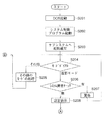
図2は、本実施形態の画像処理装置100のサブシステム制御回路52の主ルーチンを示すフローチャートである。
【0053】
サブシステム制御回路52は、モードダイアル60の設定位置を判断し、モードダイアル60が電源OFFに設定されていたならば、S102へ進み、表示部54の表示を終了状態に変更し、撮影レンズ10を沈胴収納し、保護手段102のバリアを閉じて撮像部を保護し、フラグや制御変数等を含む必要なパラメータや設定値、設定モードを不揮発性メモリ56に記録し、電源制御手段80により画像表示部28を含む画像処理装置100各部の不要な電源を遮断する等の所定の終了処理を行った後、システム制御回路50への電源供給を停止してS101に戻る。
【0054】
モードダイアル60が撮影モードに設定されていたならば、S104に進む。モードダイアル60がその他のモードに設定されていたならば、S103へ進み、サブシステム制御回路52は、システム制御回路50の電源供給を開始して、システム制御回路50は起動すると選択されたモードに応じた処理を実行する。ここで、再生モードが選択されたならば画像の再生を行ない、処理を終えたならば、S101に戻る。
【0055】
サブシステム制御回路52は、システム制御回路50の電源供給を開始して(S104)、S105へ進み、タイマーT1をスタートして、S106へ進み、バリア制御手段46によって保護手段102のバリアを開けて、ズーム制御手段44によって撮影レンズ10を撮影可能な初期位置へ移動させる。そして、サブシステム制御回路52は、システム制御回路50からの起動通知を受け取ると、S111へ進む。
【0056】
なお、システム制御回路50からの起動通知が来ない場合には、S108へ進み、S105でスタートしたタイマーT1の時間を計測して、ここで、タイマーT1の時間はシステム制御回路50への電源供給を開始してからの時間である。そして、その時間が任意の時間以上なるとタイムアウトとなり、S109へ進み、タイムアウトでない場合にはS107へ進む。ここで、前記任意の時間はシステム制御回路50のOS起動時間より長い時間とする。
【0057】
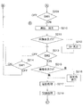
続いて、S109では、サブシステム制御回路52は、ズーム制御手段44によって撮影レンズ10を沈胴収納して、バリア制御手段46によって保護手段102のバリアを閉じ、S110へ進んで、システム制御回路50の電源供給を停止して、処理を終了する。
【0058】
次に、S111ではタイマーT2をスタートし、S112へ進み、60、62、64及び70のモードダイアル、シャッタースイッチSW1、シャッタースイッチSW2、操作部からの操作キー入力が無い場合は、S114へ進み、操作キー入力が有った場合には、S113へ進み、タイマーT2をリセットして、S114へ進む。
【0059】
そして、タイマーT2がタイムアウトしていない時はS112へ進み、タイムアウトした時は、S115へ進み、サブシステム制御回路52は、ズーム制御手段44によって撮影レンズ10を沈胴収納して、バリア制御手段46によって保護手段120のバリアを閉じ、S116へ進んで、システム制御回路50の電源供給を停止して、処理を終了する。
【0060】
ここで、タイマーT2のタイムアウトの時間は、電源制御手段80の電池残量検出の結果に基づいて、1分から10分の間で決める。電池の残量が十分にある場合は10分間とし、撮影が可能な下限に近い場合には1分間として、その中間の残量の場合は残量に応じて決める。
【0061】
また、操作部70による設定によっては、S114において、タイマーT2のタイムアウトを禁止して、タイムアウトが起きないようにすることもできるように構成されている。
【0062】
以下、図3〜図5を用いて、システム制御回路50の動作の概略を説明する。これら図3〜図5は本実施形態における画像処理装置100のシステム制御回路50側の機能を示す概略フローチャートである。
【0063】
サブシステム制御回路52による電源投入により、システム制御回路50は自らのハードウェアの初期化の後、DOSをロードし起動する(S201)。このDOSはシステムが取り扱う内部メモリ領域の確認や、外部メモリ領域の中のファイルの名前、数、量、それぞれのファイル間の関係等についてサーチした後、それらの情報についてシステムがこれらファイルやメモリを管理する為のテーブルを作成する。しかる後、システム制御回路50はシステム制御用のプログラムをロードし起動する(S202)。このシステム制御用プログラムの中でフラグや制御変数等を初期化するとともにサブシステム制御回路に起動通知を送信する(S203)。
【0064】
サブシステム制御回路52経由で読み込まれたモードダイアル60の状態が撮影モードに設定されていたならば(S204)、S106に進む。モードダイアル60がその他のモードに設定されていたならば(S204)、システム制御回路50は選択されたモードに応じた処理を実行し(S205)、処理を終えたならばS204に戻る。
【0065】
システム制御回路50は記録媒体200或いは210の動作状態が画像処理装置100の動作、特に記録媒体に対する画像データの記録再生動作に問題があるか否かを判断し(S206)、問題があるならばサブシステム制御回路52を経由して表示部54を用いて画像や音声により所定の警告表示を行った後に(S207)、S204に戻る。
【0066】
記録媒体200或いは210の動作状態に問題が無いならば(S206)、サブシステム制御回路52を経由して、表示部54を用いて画像や音声により画像処理装置100の各種設定状態の表示を行う(S208)。なお、画像表示部28の画像表示がONであったならば、画像表示部28も用いて画像や音声により画像処理装置100の各種設定状態の表示を行う。
【0067】
スルー表示状態に於いては、撮像素子12、A/D変換器16、画像処理回路20、メモリ制御回路22を介して、画像表示メモリ24に逐次書き込まれたデータを、メモリ制御回路22、D/A変換器26を介して画像表示部28により逐次表示することにより、電子ファインダー機能を実現している。
【0068】
以下、撮影モードにおける動作を説明する。
シャッタースイッチSW1及びシャッタースイッチSW2の状態はサブシステム制御回路52経由で読み込むが以下の説明では特にそのことを記述することは省略する。
【0069】
シャッタースイッチSW1が押されていないならば(S209)、S204に戻る。シャッタースイッチSW1が押されたならば(S209)、システム制御回路50は、測距処理を行って撮影レンズ10の焦点を被写体に合わせ、測光処理を行って絞り値及びシャッター時間を決定する(S210)。測光処理において、必要であればフラッシュの設定も行う。
【0070】
この測距・測光処理ステップであるS210の詳細は本発明の主旨と関係ないため省略する。
【0071】
測距・測光処理S210を終えたならば、システム制御回路50はシステム制御回路50の内部メモリ(サブシステム制御回路経由で操作部70の情報を読み込んで保持するものであり、サブシステム制御回路52の内部メモリでもよいがどちらのメモリに保持するかは本発明の主旨と関係がないので以下の説明ではシステム制御回路50の内部メモリという記述のみに省略する。)に記憶される画像表示フラグの状態を判断し(S123)、画像表示フラグが設定されていたならば画像表示部28の表示状態をスルー表示状態に設定して(S212)、S213に進む。
【0072】
シャッタースイッチSW2が押されずに(S213)、さらにシャッタースイッチSW1も解除されたならば(S214)、S204に戻る。シャッタースイッチSW2が押されたならば(S213)、システム制御回路50はシステム制御回路50の内部メモリに記憶される画像表示フラグの状態を判断し(S215)、画像表示フラグが設定されていたならば画像表示部28の表示状態を固定色表示状態に設定して(S216)、S217に進む。
【0073】
固定色表示状態においては、撮像素子12、A/D変換器16、画像処理回路20、メモリ制御回路22を介して画像表示メモリ24に書き込まれた撮影画像データの代わりに、差し替えた固定色の画像データを、メモリ制御回路22、D/A変換器26を介して画像表示部28により表示することにより、固定色の映像を電子ファインダーに表示している。
【0074】
画像表示フラグが解除されていたならば(S215)、S129に進む。
【0075】
システム制御回路50は、撮像素子12、A/D変換器16、、画像処理回路20、メモリ制御回路22を介して、或いはA/D変換器から直接メモリ制御回路22を介して、メモリ30に撮影した画像データを書き込む露光処理、及び、メモリ制御回路22そして必要に応じて画像処理回路20を用いて、メモリ30に書き込まれた画像データを読み出して各種処理を行う現像処理からなる撮影処理を実行する(S217)。
【0076】
この撮影処理ステップであるS217の詳細は本発明の主旨と関係ないため説明を省略する。
【0077】
システム制御回路50は、メモリ30に書き込まれた撮影画像データを読み出して、メモリ制御回路22そして必要に応じて画像処理回路20を用いて各種画像処理を、また、圧縮・伸長回路32を用いて設定したモードに応じた画像圧縮処理を行った後、記録媒体200或いは210へ画像データの書き込みを行う記録処理(S218)を実行するとともに、システム制御回路50の内部メモリに記憶される画像表示フラグの状態を判断し(S219)、画像表示フラグが設定されていたならば画像表示部28に今記録された画像をクイックレビュー表示を行う(S220)。
【0078】
この記録処理ステップであるS218の詳細は本発明の主旨と関係ないため説明を省略する。
【0079】
記録処理ステップS218が終了した際に、シャッタースイッチSW2が押された状態であったならば(S221)、現在の処理を繰り返す。
【0080】
画像表示フラグが設定されていた場合、記録処理S218が終了した際にシャッタースイッチSW2が押された状態であったならば、シャッタースイッチSW2が放されるまで画像表示部28におけるクイックレビュー表示を継続して撮影画像の確認を入念に行うことを可能とすることができる。
【0081】
システム制御回路50は、シャッタースイッチSW2が放されたとき、画像表示フラグが設定されていたならば(S222)、画像表示部28の表示状態をスルー表示状態に設定して(S223)、S224に進む。
【0082】
この場合、画像表示部28でのクイックレビュー表示によって撮影画像を確認した後に、次の撮影のために撮像した画像データを逐次表示するスルー表示状態にすることができる。
【0083】
シャッタースイッチSW1が押された状態であったならば(S224)、システム制御回路50は、S210に戻って次の撮影に備える。シャッタースイッチSW1が放された状態であったならば(S224)、システム制御回路50は、一連の撮影動作を終えてS204に戻る。
【0084】
このように、本実施形態のディジタルスチルカメラによれば、全体のシステム制御を行なう装置のシステム制御手段50と、レンズ保護用バリアとレンズの制御を行なう手段を合わせ持つサブシステム制御回路52を構成要素とすることにより、システム制御手段50への電源投入と同時期に、レンズ保護用バリアを開いて、レンズを撮影可能な初期位置に移動させることにより、短時間で撮影スタンバイの状態とすることが可能となる。
【0085】
なお、サブシステム制御回路52は、その処理スピードを抑え、消費電力が少なくなるように構成することにより、スピードが速く、消費電力の大きいシステム制御回路50との役割分担を明確にし、カメラ動作していない時は消費電力の大きいシステム制御回路50を停止させることで消費電力を抑え、カメラ動作中はスピードの速いシステム制御回路50を動作させることで高速処理を行ない、低消費電力と高速処理の両方の実現を可能としている。
【0086】
また、本実施形態において、サブシステム52は、動作をフローチャートで説明したように、CPU(中央処理装置)により実現しているが、CPUに係わらず、ハードワイアードロジック等によっても実現できる。その場合、ハードワイアードロジック回路は基本的に各種操作部材(60、62、64、70)の操作をシステム制御回路50に伝え、それらの操作に対するシステムの動作はシステム制御回路50が判断決定し、その結果のシステム制御回路50からの制御や表示の指示を受け、その指示に応じてレンズ、バリア、電源や表示を制御することになる。
【0087】
ただ、モードダイアル60が電源OFFモードからその他のモードに変わったとき、及び、システム制御回路50が各種操作部材(60、62、64、70)の操作が所定期間ない場合の電源断の処理(所謂オートシャットオフ)からの復帰の場合(即ち、システム制御回路50に電源が投入されたとき)のみバリア120を開き、沈胴しているレンズ10を撮影可能な初期位置に繰り出す動作を行う。これにより、システム制御回路50に電源を投入する動作に伴い、バリアの開動作(沈胴しているレンズが所定位置に移動する為に)に必要な時間(バリアを開く(レンズを駆動する)アクチュエータがDCモータの場合)、若しくはパルス数(バリアを開く(レンズを駆動する)アクチュエータがパルスモータの場合)だけバリア制御手段46(ズーム制御手段44)へ信号を出力することにより、達成可能である。
【0088】
また、サブシステム制御回路52をCPUで構成した場合には、バリアの開動作(レンズの初期位置への移動動作)が正常に完了したか否かは、サブシステム制御回路52で検出可能であるが、サブシステム制御回路52をハードワイアードロジックで構成した場合には、バリアの開動作(レンズの初期位置への移動動作)が正常に完了したか否かを、システム制御回路50が起動した後で、システム制御回路50側で行うようにする方が構成を簡略化できる。
【0089】
更に、先に説明したCPUによりサブシステム制御回路52を実現した場合には、オートシャットオフ時のバリアの閉動作もサブシステムで行っているが、これもシステム制御回路50側で行うように構成することでハードワイアードロジックで構成した場合におけるサブシステム52の構成を簡略化することが可能である。
【0090】
なお、本実施形態において説明したディジタルスチルカメラの機能を実現するように、各種のデバイスを動作させるためのプログラムコード自体及びそのプログラムコードをコンピュータに供給するための手段や、当該ディジタルスチルカメラの駆動方法、例えばステップS101〜S116や、ステップS201〜S224を実現するためのプログラムコード自体及びそのプログラムコードをコンピュータに供給するための手段、例えば、かかるプログラムコードを格納した記憶媒体は本発明の範疇に属する。
【0091】
またこの場合、所定の記憶再生装置により、記憶媒体に格納されているプログラムコードが読み出され、EEPROMが動作する。かかるプログラムコードを記憶する記憶媒体としては、例えばフロッピーディスク、ハードディスク、光ディスク、光磁気ディスク、CD−ROM、磁気テープ、不揮発性のメモリカード、ROM等の半導体記憶装置を用いることができる。
【0092】
また、コンピュータが供給されたプログラムコードを実行することにより、本実施形態の機能が実現されるだけでなく、そのプログラムコードがコンピュータにおいて稼働しているOS(オペレーティングシステム)或いは他のアプリケーションソフト等と共同して本実施形態の機能が実現される場合にもかかるプログラムコードは本発明に含まれる。
【0093】
更に、供給されたプログラムコードがコンピュータの機能拡張ボードやコンピュータに接続された機能拡張ユニットに備わるメモリに格納された後、そのプログラムコードの指示に基づいてその機能拡張ボードや機能拡張ユニットに備わるCPU等が実際の処理の一部または全部を行い、その処理によって本実施形態の機能が実現されるシステムも本発明に含まれる。
【0094】
(第2の実施の形態)
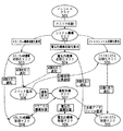
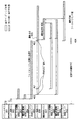
図6は本発明の第2の実施の形態によるディジタルカメラにおけるタスク構成及びその制御の流れを示すものである。また、図7は本実施の形態における撮影、ファイルアクセス可能状態までの動作を示すタイミングチャートである。図8は本実施の形態による撮像装置としてのディジタルカメラのシステム構成を示すブロック図である。
【0095】
図8において、撮像装置には、レンズユニット830、ストロボユニット840が装着され、各々着脱可能となっている。
電源スイッチ800をONすることにより、システム制御、ファイルシステム制御用の中央演算処理装置(以下、CPU)801が起動し、電源制御部850により各ブロックへの給電を開始する。
【0096】
CPU801は、画像処理制御、圧縮伸長制御、メモリ制御等を行う画像処理部802、画像メモリ808、画像表示・ビデオ出力部811等の信号処理を行う電気的機構の初期化と、露出制御部820、測距制御部821、ズーム制御部822、シャッタ制御部823、ミラー制御部824、調光制御部825等を駆動するメカニカルな機構の初期化と、記憶媒体インターフェース812、記憶媒体813の初期化及び記憶媒体813上に構成されるファイルシステムの初期化とを並列して起動する。
【0097】
本実施の形態のシステム構成においては、上記電気的機構の初期化、メカニカルな機構の初期化は短時間で完了する(図7のメカニカル的機構初期化タスク103、電気的機構初期化タスク104参照)。
【0098】
電気的機構の初期化とメカニカル的機構の初期化が完了した時点で、ファイルシステムの初期化完了を待たずに、操作スイッチ814、シャッタスイッチ815が有効となる。また、ズーム操作部材831も有効となる。使用者がズーム操作部材831を操作することにより、ズーム制御部822を介して焦点距離の変更が通知されると、CPU801は、ズーム制御部822によりレンズ群832を駆動させる。
【0099】
シャッタスイッチ815を操作しSW1がONされると、CPU801は撮影の準備を開始する。CPU801は、露出制御部820に対して測光センサ817から現在の測光情報を取得し、露出値の計算を行うように指示を出し、測距制御部821に対して測距センサ818からの情報に基づいて合焦位置を判断しながらレンズ群832を駆動させる。
【0100】
次に、シャッタスイッチ815を操作しSW2がONされると、実際の撮影を行うために、画像処理部802、タイミング発生部803を駆動して、A/Dコンバータ804、撮像素子805の制御を開始する。また、ミラー制御部824による主ミラー807の制御を行うと共に、露出制御部820による現在の露出値に対応した絞り833の制御を行い、シャッタ制御を行うことにより、現在の露出値に対応したシャッタ806の幕速制御を行い、さらに必要に応じて調光制御部825によるストロボユニット840の駆動(ストロボ発光)を制御することにより撮像素子805が露光する。
【0101】
撮像素子805の露光後、タイミング発生部803、A/Dコンバータ804により撮像素子805に蓄積された電荷を順次読み出し、ディジタルの画像データとして画像処理部802へ転送される。画像処理部802では、撮像素子805から読み出した画像データに対して現像処理、圧縮処理を行った後、画像メモリ808に一時的に格納する。この画像メモリ808に一時的に格納された画像データは、画像表示・ビデオ出力部811により閲覧することができる。また、この時点で、ファイルシステムの初期化が完了していないときは、画像データは画像メモリ808に格納されたままとなる。
【0102】
次にシャッタスイッチ(SW1やSW2)815が操作されたときは、上述と同様の制御を繰り返し、画像メモリ808が画像データで満たされるまで、撮影動作が行われる。
【0103】
画像メモリ808に画像データが存在している状態で、ファイルシステムの初期化が完了すると、直ちに画像メモリ808に格納されている画像データの記憶媒体813への書き込みが行われる。書き込みが完了すると、画像メモリ808に格納されている画像データは無効となり、次の撮影のための空き領域として使用される。
【0104】
画像メモリ808に格納されている画像データが存在し、記憶媒体813に空きがある限り、画像データの書き込みが繰り返される。また、画像データを記憶媒体に書き込んでいる途中であっても、シャッタスイッチ(SW1やSW2)815が操作されたときは、画像書き込みと並行して撮影動作が実行される。
【0105】
次に図6において、イニシャルタスク101は、システム全体の起動を行うためのタスクである。このイニシャルタスク101は、システムを起動するための初期化を行い、システムを構成するタスク群を起動し、システム起動タスク102に対してタスク起動を行う。
【0106】
システム起動タスク102は、メカニカル的機構の初期化を行うメカニカル的機構初期化タスク103に対してメカニカル機構初期化要求を発行し、電気的機構の初期化を行う電気的機構初期化タスク104に対して電気的機構初期化要求を発行し、さらに記憶媒体813にファイルを記憶するための情報をこの記憶媒体813から取得するために、ファイルシステム初期化タスク105に対してファイルシステム初期化要求を発行する。
【0107】
スイッチ監視タスク106は、使用者からの撮影開始指示を待つタスクである。このスイッチ監視タスク106は、メカニカル的機構初期化タスク103と電気的機構初期化タスク104からの初期化完了通知を受け取るまでは撮影開始指示の監視を開始しない。即ち、図7において、メカニカル的機構初期化タスク103からの初期化完了通知201と、電気的機構初期化タスク104からの初期化完了通知202とを受け付けた時点204で初めて撮影可能状態になる。
【0108】
スイッチ監視タスク106は、上記撮影可能状態の時点204以降は撮影指示を待ち、使用者の操作による撮影指示205により撮影要求を撮影制御タスク107に発行する。撮影制御タスク107は、撮影処理中状態206となり、撮影操作のためのメカニカル機構制御要求をメカニカル的機構制御タスク108に発行し、AF動作、レンズ駆動、絞り駆動、シャッタ駆動等のメカニカル的機構を制御する。
【0109】
また、撮影制御タスク107は、撮影操作のための電気的機構制御要求を電気的機構制御タスク109に発行し、撮像素子、A/Dコンバータ、デジタル信号処理部、記憶手段等の電気的機構を制御する。メカニカル的機構制御タスク108、電気的機構制御タスク109からの撮影完了通知により、撮影制御タスク107はファイルシステム制御タスク110に画像データファイル要求207を発行する。
【0110】
ファイルシステム制御タスク110は、画像データファイル要求207を受け付けると、ファイルシステム初期化タスク105からの初期化完了通知203を受け付けるまでの間(図7の204から208までの間)、画像データファイル要求207を保留状態(ペンディング状態)にしておき、一時的な記憶手段に記憶しておく。ファイルシステム制御タスク110は、ファイルシステム初期化タスク105からの初期化完了通知203を受け付けると、上記保留されている画像データファイル要求207に従って撮影した画像データを記憶媒体にファイルとして記憶する(209)。
【0111】
スイッチ監視タスク106が撮影可能状態になるためには、メカニカル的機構初期化タスク103と電気的機構初期化タスク104から初期化完了通知を受け取る必要があるので、メカニカル的機構初期化に要する時間と電気的機構初期化に要する時間を比較して長い方が、実質的に撮影可能になるまでの時間を決定している。
【0112】
本実施の形態においては、メカニカル的機構の初期化と電気的機構の初期化とは比較的短時間で完了でき、ファイルシステム初期化タスク105の初期化完了通知203を待つ必要が無いために、撮影可能になるまでの時間を短縮することができる。
【0113】
(第3の実施の形態)
図9は本発明の第3の実施の形態によるタスク構成及びその制御の流れを示したものである。また、図10は本実施の形態における記憶媒体の交換時の撮影、ファイルアクセス可能状態までの動作を示すタイミングチャートである。なお、本実施の形態による撮像装置のシステム構成は図8と同様である。
【0114】
図9におけるイニシャルタスク501は、システム全体の起動を行うためのタスクである。このイニシャルタスク501は、システムを起動するための初期化を行い、システムを構成するタスク群を起動し、システム起動タスク502に対してタスク起動を行う。
【0115】
システム起動タスク502は、メカニカル的機構の初期化を行うメカニカル的機構初期化タスク503に対してメカニカル機構初期化要求を発行し、電気的機構の初期化を行う電気的機構初期化タスク504に対して電気的機構初期化要求を発行し、さらに記憶媒体813にファイルを記憶するための情報を記憶媒体813から取得するために、ファイルシステム初期化タスク505に対してファイルシステム初期化要求を発行する。
【0116】
スイッチ監視タスク506は、使用者からの撮影開始指示、記憶媒体の交換検出を待つタスクである。スイッチ監視タスク506は、メカニカル的機構初期化タスク503と電気的機構初期化タスク504からの初期化完了通知を受け取るまでは撮影開始指示の監視を開始しない。即ち、メカニカル的機構初期化タスク503からの初期化完了通知と、電気的機構初期化タスク504からの初期化完了通知とを受け付けた時点で初めて撮影可能状態になる。
【0117】
さらに、ファイルシステム初期化タスク505において初期化が完了すると、ファイルシステム制御タスク510に対して初期化完了通知を発行し、ファイルシステム制御タスク510はファイルアクセス可能な状態となる。
【0118】
図10において、スイッチ監視タスク506は、使用者による記憶媒体813の交換操作601を検出すると、ファイルシステム初期化タスク505及びファイルシステム制御タスク510に対して記憶媒体交換通知602を発行する。
【0119】
ファイルシステム初期化タスク505は、記憶媒体交換通知602を受け付けると、記憶媒体に関する情報(記憶媒体の種別情報、記憶媒体の全体容量、現在までの使用容量、現在の空き容量、ファイルフォーマット、現在の最新ファイル情報等)を記憶媒体から直接読み出すため、ファイルシステム初期化処理中状態610となる。
【0120】
また、ファイルシステム制御タスク510は、ファイルアクセス不可能な状態となる。即ち、記憶媒体の交換操作601の操作時点603からファイルシステム初期化中・ファイルアクセス不可・撮影可能な状態となる。
【0121】
記憶媒体の交換操作時点603以降は、使用者の操作による撮影指示604により撮影要求を撮影制御タスク507に発行する。撮影制御タスク507は、撮影処理中状態605となり、撮影操作のためのメカニカル機構制御要求をメカニカル的機構制御タスク508に発行し、レンズ、絞り、シャッタを制御する。また、撮影制御タスク507は、撮影操作のための電気的機構制御要求を電気的機構制御タスク509に発行し、撮像素子、A/Dコンバータ、デジタル信号処理部、記憶手段の制御を行う。
【0122】
メカニカル的機構制御タスク508及び電気的機構制御タスク509からの撮影完了通知により、撮影制御タスク507はファイルシステム制御タスク510に画像データファイル要求606を発行する。ファイルシステム制御タスク510は、画像データファイル要求606を受け付けると、ファイルシステム初期化タスク505からの初期化完了通知607を受け付けるまでの間(603から608までの間)、画像データファイル要求606を保留状態(ペンディング状態)にしておき、一時的な記憶手段に記憶しておく。
【0123】
ファイルシステム制御タスク510は、ファイルシステム初期化タスク505からの初期化完了通知607を受け付けると、保留されている画像データファイル要求606に従って撮影した画像データを記憶媒体にファイルとして記憶する(609)。
【0124】
このように、本実施の形態によれば、記憶媒体の交換操作によるファイルシステムの初期化処理中においても、メカニカル機構の制御、電気的機構の制御が動作することにより、撮影動作が可能となる。
【0125】
(第4の実施の形態)
図11は本発明の第4の実施の形態による撮影、ファイルアクセス可能状態までの動作を示すタイミングチャートである。図12は本実施の形態による撮像装置としてのディジタルカメラのシステム構成である。また、本実施の形態によるタスク構成及びその制御の流れは図6と同様である。
【0126】
図12において、ディジタルカメラにはストロボユニット919が内蔵され、沈胴式のレンズ916、レンズを保護するレンズバリア917が装備されている。
【0127】
電源スイッチ900をONすることにより、システム制御、ファイルシステム制御用のCPU901が起動し、電源制御部930により、各ブロックヘの給電を開始する。CPU901は、画像処理制御、圧縮伸長制御、メモリ制御等を行う画像処理部902、画像メモリ908、画像表示・ビデオ出力部910等の電気的機構の初期化を行い、露出制御部920、測距制御部921、ズーム制御部922、バリア制御部923のメカニカル的機構の初期化、記憶媒体インターフェース911、記憶媒体912の初期化及び記憶媒体912上に構成されるファイルシステムの初期化を並列して起動する。
【0128】
本実施の形態によるシステム構成においては、電気的機構の初期化は短時間で完了する(図11の電気的機構初期化タスク104)。
メカニカル的機構の初期化では、バリア制御部923により、レンズバリア917が開かれ、レンズバリア917が開いた状態で、測距制御部921、ズーム制御部922によりレンズ群916を所定の位置まで移動する。
【0129】
露出制御部920では、シャッタ、絞り906を所定の位置まで移動させる(図11のメカニカル的機構初期化タスク103)。電気的機構の初期化とメカニカル的機構の初期化が完了した時点で、ファイルシステムの初期化完了を待たずに、操作スイッチ913、シャッタスイッチ914のうちSW1が有効となる。
【0130】
使用者が操作スイッチ913のズーム操作部材を操作することにより、CPU901は、ズーム制御部922によりレンズ群916及び光学ファインダ918を駆動させる。
【0131】
シャッタスイッチ914のうちSW1がONされると、CPU901は撮影の準備を開始する。CPU901は、画像処理部902、タイミング発生部903、A/Dコンバータ904、撮像素子905を駆動し、露出制御部920により絞り906を調整して、撮像素子905に露光させる。撮像素子905が露光すると、タイミング発生部903、A/Dコンバータ904により撮像素子905に蓄積された電荷を順次読み出し、ディジタル画像データとして画像処理部902へ転送される。
【0132】
画像処理部902では、撮像素子905より読み出した画像データに対して現像処理を行い、画像メモリ907に格納する。画像メモリ907に格納された画像データは、画像表示・ビデオ出力部910により閲覧することができる。光学ファインダ918を使用しているときは、画像メモリ907への画像データの書き込み、画像表示・ビデオ出力部910での閲覧はできない。
【0133】
また、測距制御部921は、画像処理部902又は測距センサからの情報に基づいて合焦位置を判断しながらレンズ群916を駆動させる。この状態では、シャッタスイッチ914のうちSW2がONされると、直ぐに撮影できる状態になっている。
【0134】
ファイルシステムの初期化が完了すると、シャッタスイッチ914のうちSW2も有効となり、全スイッチが有効な状態となる。
【0135】
シャッタスイッチ914のうちSW2がONされると、既に測距は完了しており、レンズ916等の光学系のメカは合焦位置にあるため、CPU901は直ちに撮影動作を行い、画像処理部902、タイミング発生部903、A/Dコンバータ904、撮像素子905を駆動し、露出制御部920により絞り906を調整して撮像素子905に露光させる。
【0136】
撮像素子905の露光後、タイミング発生部903、A/Dコンバータ904により撮像素子905に蓄積された電荷を順次読み出し、ディジタル画像データとして画像処理部902に転送される。画像処理部902では、撮像素子905から読み出した画像データに対して現像処理、圧縮処理を行い、画像メモリ908に一時的に格納する。画像メモリ908へ一時的に格納された画像データは、画像表示・ビデオ出力部910により閲覧することができる。
【0137】
画像メモリ908に格納されている画像データは、直ちに記憶媒体912への書き込みが行われ、書き込みが完了すると、画像メモリ908へ格納されている画像データは無効となり、次の撮影のための空き領域として使用される。また、画像データを記憶媒体に書き込んでいる途中であっても、シャッタスイッチ(SW1やSW2)914が操作されたときは画像書き込みと並行して撮影動作が実行される。
【0138】
図6において、イニシャルタスク101は、システム全体の起動を行うためのタスクであり、システムを起動するための初期化を行い、システムを構成するタスク群を起動し、システム起動タスク102に対してタスク起動を行う。システム起動タスク102は、メカニカル的機構の初期化を行うメカニカル的機構初期化タスク103に対してメカニカル機構初期化要求を発行し、電気的機構の初期化を行う電気的機構初期化タスク104に対して電気的機構初期化要求を発行し、さらに記憶媒体912にファイルを記憶するための情報を記憶媒体から取得するために、ファイルシステム初期化タスク105に対してファイルシステム初期化要求を発行する。
【0139】
スイッチ監視タスク106は、使用者からの撮影開始指示を待つタスクである。このスイッチ監視タスク106は、メカニカル的機構初期化タスク103、電気的機構初期化タスク104の初期化完了通知を受け取るまでは撮影準備開始指示の監視を開始しない。即ち、図11において、メカニカル的機構初期化タスク103からの初期化完了通知701と、電気的機構初期化タスク104からの初期化完了通知702とを受け付けた時点704で初めて撮影準備可能状態になる。
【0140】
スイッチ監視タスク106は、上記撮影準備可能状態の時点704以降は撮影指示のうち、撮影準備指示(SW1)705を待ち、使用者の操作による撮影準備指示(SW1)705により撮影準備要求を撮影制御タスク107に発行する。撮影制御タスク107は撮影準備処理中状態706となり、撮影操作のためのメカニカル機構制御要求をメカニカル的機構制御タスク108に発行し、レンズズーム制御、測距制御(AF動作)を行う。
【0141】
また、撮影制御タスク107は、撮影操作のための電気的機構制御要求を電気的機構制御タスク109に発行し、撮像素子駆動、露出制御(AE動作)、A/Dコンバータ、デジタル信号処理部、画像表示・ビデオ出力(エレクトリックビューファインダー)、ストロボの充電動作の制御を行う。
【0142】
メカニカル的機構制御タスク108からのレンズズーム動作完了、AF動作完了が撮影制御タスク107に通知され、撮影準備完了状態707となる。ファイルシステム初期化タスク105においてファイルシステムの初期化完了すると、スイッチ監視タスク106に対して初期化完了通知703が発行され、これを受けてスイッチ監視タスク106は撮影指示(SW2)708を受け付け可能になる。
【0143】
スイッチ監視タスク106が、撮影指示(SW2)708を受け付けると、撮影制御タスク107へ撮影実行要求を発行する。撮影制御タスク107は、既に撮影準備完了状態707となっているので、改めてメカニカル的機構制御タスク108に対して撮影準備を要求することなく、撮影実行を要求することが可能となる(AFを実行し直す必要がないため、直ぐにシャッタをきることが可能)。
【0144】
電気的機構制御タスク109も撮像素子、A/Dコンバータ、デジタル信号処理部、記憶手段の制御を行う。メカニカル的機構制御タスク108及び電気的機構制御タスク109からの撮影動作の完了通知が撮影制御タスク107へ通知されると、ファイルシステム制御タスク110へ画像データファイル要求を発行し、ファイルシステム制御タスク110は画像データ記憶中711となり、画像データの記憶媒体への書き込みを行う。
【0145】
このように、本実施の形態によれば、ファイルシステムの初期化処理中に、光学的なメカニカル的機構を動作させ、レンズズーム動作、AF動作、AE動作を行うことにより、ファイルシステム初期化完了後、直ちに撮影指示を行った場合、直ちに撮影動作(絞りの制御、シャッタ制御、撮像制御)を行うことが可能となる。
【0146】
なお、上記第2〜第4の実施の形態において、メカニカル的機構の初期化動作と電気的な機構の初期化動作とファイルシステムの初期化動作とを並列に行うための制御装置として、複数のマイクロコンピュータを用いるようにしてよい。
【0147】
また、上記各初期化動作を並列に行うために、前記各初期化動作からの割り込み処理によるリアルタイムマルチタスクモニタシステムを用いてよい。
また、上記各初期化動作を並列に行うために、ファイルシステムの初期化動作時の記憶媒体からのデータ転送をDMA(Direct Memory Access)により行っている空き時間に、メカニカル的機構の初期化動作と電気的な機構初期化動作とを実行するようにしてよい。
さらに、上記各初期化動作を並列に行うために、時分割処理によりメカニカル的機構の初期化動作と電気的な機構初期化動作とを実行するようにしてよい。
【0148】
なお、上記第2〜4の実施形態において説明した撮像装置の機能を実現するように、各種のデバイスを動作させるためのプログラムコード自体及びそのプログラムコードをコンピュータに供給するための手段や、図1、図3、図9で説明した制御の流れを実現するためのプログラムコード自体及びそのプログラムコードをコンピュータに供給するための手段、例えば、かかるプログラムコードを格納したプログラムメモリ809、908等は本発明による記憶媒体を構成する。
【0149】
またこの場合、所定の記憶再生装置により、記憶媒体に格納されているプログラムコードが読み出され、EEPROMが動作する。かかるプログラムコードを記憶する記憶媒体としては、例えばフロッピーディスク、ハードディスク、光ディスク、光磁気ディスク、CD−ROM、磁気テープ、不揮発性のメモリカード、ROM、RAM等の半導体記憶装置等を用いることができる。
【0150】
また、コンピュータが供給されたプログラムコードを実行することにより、本実施形態の機能が実現されるだけでなく、そのプログラムコードがコンピュータにおいて稼働しているOS(オペレーティングシステム)或いは他のアプリケーションソフト等と共同して上記各実施の形態の機能が実現される場合にもかかるプログラムコードは本発明に含まれる。
【0151】
更に、供給されたプログラムコードがコンピュータの機能拡張ボードやコンピュータに接続された機能拡張ユニットに備わるメモリに格納された後、そのプログラムコードの指示に基づいてその機能拡張ボードや機能拡張ユニットに備わるCPU等が実際の処理の一部または全部を行い、その処理によって各実施の形態の機能が実現されるシステムも本発明に含まれる。
【0152】
【発明の効果】
本発明によれば、短時間で撮影可能な状態にすることができる。
【図面の簡単な説明】
【図1】本発明の第1の実施の形態によるディジタルスチルカメラの主要構成を示すブロック図である。
【図2】本発明の第1の実施の形態の主ルーチンのフローチャートの一部である。
【図3】本発明の第1の実施の形態におけるシステム制御回路の動作の概略を説明するためのフローチャートである。
【図4】図3に引き続きシステム制御回路の動作の概略を説明するためのフローチャートである。
【図5】図4に引き続きシステム制御回路の動作の概略を説明するためのフローチャートである。
【図6】本発明の第2、第4の実施の形態によるディジタルカメラのタスク構成及び制御の流れを示す構成図である。
【図7】本発明の第2の実施の形態による動作を示すタイミングチャートである。
【図8】本発明の第2、第3の実施の形態によるディジタルカメラの構成を示すブロック図である。
【図9】本発明の第3の実施の形態によるディジタルカメラのタスク構成及び制御の流れを示す構成図である。
【図10】本発明の第3の実施の形態による動作を示すタイミングチャートである。
【図11】本発明の第4の実施の形態による動作を示すタイミングチャートである。
【図12】本発明の第4の実施の形態によるディジタルカメラの構成を示すブロック図である。
【図13】従来のディジタルカメラのタスク構成及び制御の流れを示す構成図である。
【図14】従来のディジタルカメラの動作を示すタイミングチャートである。
【符号の説明】
10:撮影レンズ
12:シャッター
14:撮像素子
16:A/D変換器
18:タイミング発生回路
20:画像処理回路
22:メモリ制御回路
24:画像表示メモリ
26:D/A変換器
28:画像表示部
30:メモリ
32:画像圧縮・伸長回路
40:露光制御手段
42:測距制御手段
44:ズーム制御手段
46:バリア制御手段
48:フラッシュ
50:システム制御回路
52:サブシステム制御回路
54:表示部
56:不揮発性メモリ
60:モードダイアルスイッチ
62:シャッタースイッチSW1
64:シャッタースイッチSW2
66:画像表示ON/OFFスイッチ
68:クイックレビューON/OFFスイッチ
70:操作部
80:電源制御手段
82、84、92、96、206:コネクタ
86:電源手段
90、94、204、214:インタフェース
100:画像処理装置
120:保護手段
140:光学ファインダ
200、210:記録媒体
202、214:記録部
101、301、501:イニシャルタスク
102、302、502:システム起動タスク
103、303、503:メカニカル的機構初期化タスク
104、304、504:電気的機構初期化タスク
105、305、505:ファイルシステム初期化タスク
106、306、506:スイッチ監視タスク
107、307、507:撮影制御タスク
108、308、508:メカニカル的機構制御タスク
109、309、509:電気的機構制御タスク
110、310、510:ファイルシステム制御タスク
201、401:メカニカル的機構初期化タスクからの初期化完了通知
202、402:電気的機構初期化タスクからの初期化完了通知
203、405:ファイルシステム初期化タスクからの初期化完了通知
207:撮影制御タスクからの画像データファイル要求
602:スイッチ監視タスクからの記憶媒体交換通知
606:撮影制御タスクからの画像データファイル要求
607:ファイルシステム初期化タスクからの初期化完了通知
800、900:電源スイッチ
801、901:中央演算処理装置
802、902:画像処理部
803、903:タイミング発生部
804、904:A/Dコンバータ
805、905:撮像素子
806:メカニカルシャッタ
807:ミラーユニット
808、907:画像メモリ
809、908:プログラム格納メモリ
810、909:プログラム作業用メモリ
811、910:画像表示・ビデオ出力部
812、911:記憶媒体インターフェース
813、912:記憶媒体
814、913:操作スイッチ
815、914:シャッタスイッチ(レリーズスイッチ)
816、915:表示装置
817:測光センサ
818:測距センサ
819:調光センサ
820、920:露出制御部
821、921:測距制御部
822、922:ズーム制御部
823:シャッタ制御部
824:ミラー制御回路
825:調光制御部
830:レンズユニット(交換レンズ)
831:ズーム操作部材(ズームリング)
832:レンズ群
833:絞り、絞り駆動回路
840:ストロボユニット
850、930:電源制御部
906:レンズシャッタ、絞り駆動回路
917:レンズバリア、レンズバリア駆動回路
918:光学ファインダ、光学ファインダズーム駆動回路[0001]
BACKGROUND OF THE INVENTION
The present invention, ElectricChild device, driving method of electronic device, and computer-readable storage mediumThe
[0002]
[Prior art]
System control devices in electronic devices such as digital cameras need to perform various processes such as file management, communication with external devices, image processing, and compression processing as well as performing various controls related to shooting, etc. The above-described processing is realized by installing an OS in an apparatus that performs overall system control. In addition, recently, there is a strong demand for downsizing digital cameras and the like, and the lens is retracted into the camera body to improve portability, and a lens protection barrier is provided to protect the lens. Yes.
[0003]
On the other hand, an imaging apparatus such as a digital camera having a storage medium for storing captured image data and a file system for storing the image data in the storage medium has been developed. However, restrictions on the start time of the file system and information on the above storage medium (storage medium type information, total capacity of the storage medium, current used capacity, current free capacity, file format, current latest file information, etc.) Due to the time required to read the data from the storage medium, it was impossible to perform the photographing operation even though the initialization operation of the mechanical mechanism and the initialization operation of the electrical mechanism were completed. Particularly in recent years, with the increase in the storage capacity of the storage medium, the time required for initialization of the file system has increased, and the entire system startup time has become longer.
[0004]
FIG. 13 shows an outline of a task configuration and a control flow thereof in a digital camera having the conventional file system. FIG. 14 is a timing chart showing the operation up to the photographing enabled state in the conventional digital camera.
[0005]
In FIG. 13, an
[0006]
The
[0007]
The
[0008]
The
[0009]
The
[0010]
In order for the
[0011]
The initialization time of the file system depends on the speed and capacity of the storage medium installed in the imaging device and the content of the information acquired directly from the storage medium. Time tends to be longer.
[0012]
Thus, the long time from when the imaging device is activated until it is possible to shoot is contrary to the user's request for the imaging device to be able to shoot immediately when it wants to shoot, It is stressful for the user.
[0013]
Conventionally, in order to avoid such a state, the imaging apparatus has information related to the mounted storage medium (storage medium type information, total capacity of the storage medium, current used capacity, current free capacity, file format, Current latest file information, etc.) is stored in a non-volatile storage device or the like, and stored regardless of whether the power of the imaging device is turned on or off. It has been attempted to reduce the stress on the user by reading from the storage device and shortening the time from when the imaging device is activated to when imaging is possible.
[0014]
[Problems to be solved by the invention]
The above-described digital camera equipped with an OS for overall system control has a problem that it takes a relatively long time to start the OS when the system control device is powered on.
[0015]
Also, it takes time for mechanical operations such as opening the lens protection barrier and moving the lens to an initial position where photographing can be performed, and there is a possibility that a shutter chance will be missed when combined with the OS startup time. There was a problem of becoming higher.
[0016]
In the above-described digital camera having the file system of FIG. 13, the storage medium is mounted with the camera turned off, and the storage medium is replaced when the power is turned on immediately thereafter or with the power turned on. When it is necessary to read out information related to the storage medium directly from the storage medium by performing an initialization operation of the file system as in the case or the like, the time for reading information from the storage medium becomes long and it becomes possible to shoot. The time was long. For this reason, there is a problem that the possibility of missing a photo opportunity increases.
[0017]
The present invention has been made in order to solve the above-described problems, and enables a main operation to be performed quickly in a short time. That is, in the case of a digital camera, a shooting is possible and a photo opportunity is obtained. The purpose is not to let go.
[0018]
[Means for Solving the Problems]
The electronic apparatus according to the present invention is provided separately from the first system control means for loading a system control program and executing processing corresponding to the mode, and the first system control means, and the lens is disposed from the retracted position. Perform processing to control movement to a position where shooting is possibleThe rated power consumption is smaller than that of the first system control meansSecond system control means, and the second system control means moves the lens to a position where photographing can be performed when power is turned on and supplies power to the first system control means. The first system control means loads the system control program in parallel with receiving the power supply from the second system control means so that the system control program can be activated, and operates the control application to operate the mode. The process according to this is performed.
[0019]
According to another aspect of the invention, there is provided a driving method for an electronic device, which includes a first system control unit that loads a system control program and executes a process according to a mode, and the first system control unit. Executes processing to control movement from the retracted position to a position where shooting is possibleThe rated power consumption is smaller than that of the first system control meansA method of driving an electronic apparatus comprising a second system control means, wherein the second system control means supplies power to the first system control means, and the second system control means In parallel with receiving the power supply, the first system control means loads the system control program so that it can be activated, and operates the control application to execute processing corresponding to the mode. It is characterized by performing by.
[0020]
BookInventionThe computer-readable storage medium stores a program for causing a computer to function as each unit of the electronic device.
According to another aspect of the present invention, a program for causing a computer to execute the electronic device driving method is stored.
[0021]
In the storage medium of the present invention, a program for causing a computer to function as each unit of the electronic device is stored.
[0022]
In another storage medium of the present invention, a program for causing a computer to execute the driving method of the electronic device is stored.
[0026]
DETAILED DESCRIPTION OF THE INVENTION
Hereinafter, specific embodiments of the present invention will be described in detail with reference to the drawings.
(First embodiment)
FIG. 1 is a block diagram showing a main configuration of a digital still camera which is an electronic apparatus according to the first embodiment of the present invention. In FIG. 1, 100 is an image processing apparatus, 10 is a photographing lens, 12 is a shutter having a diaphragm function, 14 is an image sensor that converts an optical image into an electric signal, and 16 is a digital signal output from the
[0027]
Reference numeral 18 denotes a timing generation circuit that supplies a clock signal and a control signal to the
[0028]
A
[0029]
[0030]
[0031]
A compression / decompression circuit 32 compresses and decompresses image data by adaptive discrete cosine transform (ADCT) or the like, reads an image stored in the
[0032]
[0033]
[0034]
Reference numeral 54 denotes a display device that displays an operation state, a message, and the like using characters, images, sounds, and the like in accordance with execution of a program in the
[0035]
Among the display contents of the display unit 54, what is displayed on the LCD or the like includes single shot / continuous shooting display, self-timer display, compression rate display, number of recorded pixels, number of recorded pixels, number of remaining images that can be captured, shutter Speed display, Aperture value display, Exposure compensation display, Flash display, Red-eye reduction display, Macro shooting display, Buzzer setting display, Clock battery level display, Battery level display, Error display, Multi-digit number information display and recording There are a display state of the
[0036]
Among the display contents of the display unit 54, what is displayed in the
[0037]
Reference numeral 56 denotes an electrically erasable / recordable nonvolatile memory such as an EEPROM.
[0038]
[0039]
Here, the operation means of each of these members will be specifically described.
[0040]
[0041]
[0042]
Reference numeral 70 denotes an operation unit composed of various buttons, a touch panel, and the like. A menu button, a set button, a macro button, a multi-screen playback page break button, a flash setting button, a single shooting / continuous shooting / self-timer switching button, menu movement + (plus) Button, menu shift- (minus) button, playback image shift + (plus) button, playback image- (minus) button, shooting image quality selection button, exposure correction button, date / time setting button, and the like.
[0043]
Reference numeral 80 denotes a power supply control means, which includes a battery detection circuit, a DC-DC converter, a switch circuit for switching a block to be energized, etc., and detects the presence / absence of a battery, the type of battery, the remaining battery level, and the detection result In addition, the DC-DC converter is controlled based on an instruction from the
[0044]
[0045]
[0046]
In this embodiment, it is assumed that there are two interfaces and connectors for attaching the recording medium. Of course, the interface and the connector for attaching the recording medium may have a single or a plurality of systems and any number of systems. Moreover, it is good also as a structure provided with combining the interface and connector of a different standard.
[0047]
The interface and connector may be configured using a PCMCIA card, a CF (compact flash) card, or the like that conforms to a standard.
Further, when the
[0048]
A protection unit 120 is a barrier that prevents the imaging unit from being soiled or damaged by covering the imaging unit including the
[0049]
Reference numeral 140 denotes an optical viewfinder, which can take an image using only the optical viewfinder without using the electronic viewfinder function of the image display unit 28. In the optical viewfinder 140, some functions of the display unit 54, for example, a focus display, a camera shake warning display, a flash charge display, a shutter speed display, an aperture value display, an exposure correction display, and the like are installed.
[0050]
[0051]
[0052]
The operation of the digital still camera of this embodiment will be described below.
FIG. 2 is a flowchart showing a main routine of the subsystem control circuit 52 of the
[0053]
The subsystem control circuit 52 determines the setting position of the
[0054]
If the
[0055]
The subsystem control circuit 52 starts power supply to the system control circuit 50 (S104), proceeds to S105, starts the timer T1, proceeds to S106, and opens the barrier of the protection means 102 by the barrier control means 46. Then, the
[0056]
When the activation notification is not received from the
[0057]
Subsequently, in S109, the subsystem control circuit 52 retracts the taking
[0058]
Next, in S111, the timer T2 is started, and the process proceeds to S112. If there is no mode dial of 60, 62, 64, and 70, shutter switch SW1, shutter switch SW2, or operation key input from the operation unit, the process proceeds to S114. If there is an operation key input, the process proceeds to S113, the timer T2 is reset, and the process proceeds to S114.
[0059]
If the timer T2 has not timed out, the process proceeds to S112. If the timer T2 has timed out, the process proceeds to S115. The subsystem control circuit 52 retracts the taking
[0060]
Here, the time-out time of the timer T2 is determined between 1 minute and 10 minutes based on the result of detection of the remaining battery level of the power control means 80. When the remaining battery level is sufficient, the time is 10 minutes, when the battery is close to the lower limit where photography is possible, the time is 1 minute.
[0061]
Further, depending on the setting by the operation unit 70, in S114, the timeout of the timer T2 can be prohibited so that the timeout does not occur.
[0062]
Hereinafter, the outline of the operation of the
[0063]
When the power is turned on by the subsystem control circuit 52, the
[0064]
If the state of the
[0065]
The
[0066]
If there is no problem in the operation state of the
[0067]
In the through display state, the data sequentially written in the
[0068]
The operation in the shooting mode will be described below.
The states of the shutter switch SW1 and the shutter switch SW2 are read via the subsystem control circuit 52, but in the following description, this is not particularly described.
[0069]
If the shutter switch SW1 has not been pressed (S209), the process returns to S204. If the shutter switch SW1 is pressed (S209), the
[0070]
Details of this distance measurement / photometry processing step S210 are not related to the gist of the present invention, and are therefore omitted.
[0071]
When the distance measurement / photometry process S210 is completed, the
[0072]
If the shutter switch SW2 is not pressed (S213) and the shutter switch SW1 is also released (S214), the process returns to S204. If the shutter switch SW2 is pressed (S213), the
[0073]
In the fixed color display state, instead of the captured image data written in the
[0074]
If the image display flag has been canceled (S215), the process proceeds to S129.
[0075]
The
[0076]
The details of step S217, which is the photographing processing step, are not related to the gist of the present invention, and thus description thereof is omitted.
[0077]
The
[0078]
The details of this recording processing step S218 are not related to the gist of the present invention, and the description thereof will be omitted.
[0079]
If the shutter switch SW2 has been pressed when the recording process step S218 is completed (S221), the current process is repeated.
[0080]
When the image display flag is set, if the shutter switch SW2 is pressed when the recording process S218 is completed, the quick review display on the image display unit 28 is continued until the shutter switch SW2 is released. Thus, it is possible to carefully check the captured image.
[0081]
If the image display flag is set when the shutter switch SW2 is released (S222), the
[0082]
In this case, after confirming the captured image by the quick review display on the image display unit 28, it is possible to enter a through display state in which image data captured for the next imaging is sequentially displayed.
[0083]
If the shutter switch SW1 has been pressed (S224), the
[0084]
As described above, according to the digital still camera of the present embodiment, the system control means 50 of the apparatus for performing the overall system control and the subsystem control circuit 52 having both the lens protection barrier and the means for controlling the lens are configured. By using the element, the lens protection barrier is opened at the same time as the power supply to the
[0085]
The subsystem control circuit 52 is configured so as to reduce the processing speed and reduce the power consumption, thereby clarifying the role sharing with the
[0086]
In this embodiment, the subsystem 52 is realized by a CPU (central processing unit) as described in the flowchart, but can be realized by a hard wired logic or the like regardless of the CPU. In that case, the hard wired logic circuit basically transmits the operation of the various operation members (60, 62, 64, 70) to the
[0087]
However, when the
[0088]
When the subsystem control circuit 52 is constituted by a CPU, the subsystem control circuit 52 can detect whether or not the barrier opening operation (the movement operation of the lens to the initial position) has been normally completed. However, when the subsystem control circuit 52 is configured by hard wired logic, after the
[0089]
Further, when the subsystem control circuit 52 is realized by the CPU described above, the barrier closing operation at the time of auto shut-off is also performed by the subsystem, but this is also configured to be performed by the
[0090]
In order to realize the functions of the digital still camera described in the present embodiment, program code itself for operating various devices, means for supplying the program code to a computer, and driving of the digital still camera A method, for example, steps S101 to S116, program code itself for realizing steps S201 to S224, and means for supplying the program code to a computer, for example, a storage medium storing such program code are within the scope of the present invention. Belongs.
[0091]
In this case, the program code stored in the storage medium is read out by a predetermined storage / reproduction device, and the EEPROM operates. As a storage medium for storing the program code, for example, a semiconductor storage device such as a floppy disk, a hard disk, an optical disk, a magneto-optical disk, a CD-ROM, a magnetic tape, a nonvolatile memory card, and a ROM can be used.
[0092]
Further, by executing the program code supplied by the computer, not only the functions of the present embodiment are realized, but also the OS (operating system) or other application software running on the computer. Such a program code is also included in the present invention when the functions of the present embodiment are realized jointly.
[0093]
Further, after the supplied program code is stored in the memory provided in the function expansion board of the computer or the function expansion unit connected to the computer, the CPU provided in the function expansion board or function expansion unit based on the instruction of the program code A system in which the functions of the present embodiment are realized by performing part or all of the actual processing and the processing is also included in the present invention.
[0094]
(Second Embodiment)
FIG. 6 shows a task configuration and a control flow thereof in the digital camera according to the second embodiment of the present invention. FIG. 7 is a timing chart showing the operation up to the photographing and file accessible state in the present embodiment. FIG. 8 is a block diagram showing a system configuration of a digital camera as an imaging apparatus according to the present embodiment.
[0095]
In FIG. 8, a
By turning on the
[0096]
The
[0097]
In the system configuration of this embodiment, the initialization of the electrical mechanism and the initialization of the mechanical mechanism are completed in a short time (see the mechanical
[0098]
When the initialization of the electrical mechanism and the initialization of the mechanical mechanism are completed, the
[0099]
When the shutter switch 815 is operated and SW1 is turned on, the
[0100]
Next, when the shutter switch 815 is operated and SW2 is turned on, the
[0101]
After exposure of the
[0102]
Next, when the shutter switch (SW1 or SW2) 815 is operated, the same control as described above is repeated, and the photographing operation is performed until the
[0103]
When the initialization of the file system is completed in a state where image data exists in the
[0104]
As long as the image data stored in the
[0105]
Next, in FIG. 6, an
[0106]
The
[0107]
The
[0108]
The
[0109]
Also, the shooting control task 107 issues an electrical mechanism control request for shooting operation to the electrical
[0110]
When the file
[0111]
In order for the
[0112]
In this embodiment, the initialization of the mechanical mechanism and the initialization of the electrical mechanism can be completed in a relatively short time, and there is no need to wait for the
[0113]
(Third embodiment)
FIG. 9 shows a task configuration and its control flow according to the third embodiment of the present invention. FIG. 10 is a timing chart showing the operations up to the photographing and file accessible state when the storage medium is replaced in the present embodiment. The system configuration of the imaging apparatus according to this embodiment is the same as that shown in FIG.
[0114]
An
[0115]
The
[0116]
The
[0117]
Further, when the initialization is completed in the file system initialization task 505, an initialization completion notification is issued to the file
[0118]
In FIG. 10, when the
[0119]
Upon receiving the storage
[0120]
Further, the file
[0121]
After the storage medium
[0122]
In response to the shooting completion notification from the mechanical
[0123]
When the file
[0124]
As described above, according to the present embodiment, even during the initialization of the file system by the replacement operation of the storage medium, the photographing operation can be performed by controlling the mechanical mechanism and the electrical mechanism. .
[0125]
(Fourth embodiment)
FIG. 11 is a timing chart showing the operation up to the photographing and file accessible state according to the fourth embodiment of the present invention. FIG. 12 shows a system configuration of a digital camera as an imaging apparatus according to the present embodiment. The task configuration and control flow according to this embodiment are the same as those in FIG.
[0126]
In FIG. 12, the digital camera has a built-in
[0127]
When the
[0128]
In the system configuration according to the present embodiment, the initialization of the electrical mechanism is completed in a short time (electrical
In initialization of the mechanical mechanism, the
[0129]
The
[0130]
When the user operates the zoom operation member of the
[0131]
When SW1 of the
[0132]
The
[0133]
The distance
[0134]
When the initialization of the file system is completed, SW2 of the
[0135]
When the switch SW2 of the
[0136]
After exposure of the
[0137]
The image data stored in the
[0138]
In FIG. 6, an
[0139]
The
[0140]
The
[0141]
Also, the shooting control task 107 issues an electrical mechanism control request for shooting operation to the electrical
[0142]
Completion of the lens zoom operation and AF operation completion from the mechanical
[0143]
When the
[0144]
The electrical
[0145]
As described above, according to the present embodiment, the file system initialization is completed by operating the optical mechanical mechanism and performing the lens zoom operation, the AF operation, and the AE operation during the initialization process of the file system. Thereafter, when a shooting instruction is given immediately, shooting operations (aperture control, shutter control, imaging control) can be performed immediately.
[0146]
In the second to fourth embodiments, there are a plurality of control devices for performing the initialization operation of the mechanical mechanism, the initialization operation of the electrical mechanism, and the initialization operation of the file system in parallel. A microcomputer may be used.
[0147]
Further, in order to perform the initialization operations in parallel, a real-time multitask monitor system using an interrupt process from the initialization operations may be used.
In addition, in order to perform the above initialization operations in parallel, the initialization operation of the mechanical mechanism is performed during the idle time in which data transfer from the storage medium during the initialization operation of the file system is performed by DMA (Direct Memory Access). And electrical mechanism initialization operation may be executed.
Furthermore, in order to perform the above initialization operations in parallel, the initialization operation of the mechanical mechanism and the electrical mechanism initialization operation may be executed by time division processing.
[0148]
The program code itself for operating various devices and the means for supplying the program code to the computer so as to realize the functions of the imaging apparatus described in the second to fourth embodiments, FIG. The program code itself for realizing the control flow described in FIG. 3 and FIG. 9 and means for supplying the program code to the computer, such as
[0149]
In this case, the program code stored in the storage medium is read out by a predetermined storage / reproduction device, and the EEPROM operates. As a storage medium for storing the program code, for example, a floppy disk, a hard disk, an optical disk, a magneto-optical disk, a CD-ROM, a magnetic tape, a nonvolatile memory card, a semiconductor storage device such as a ROM, a RAM, or the like can be used. .
[0150]
Further, by executing the program code supplied by the computer, not only the functions of the present embodiment are realized, but also the OS (operating system) or other application software running on the computer. Such a program code is also included in the present invention even when the functions of the above-described embodiments are realized together.
[0151]
Further, after the supplied program code is stored in the memory provided in the function expansion board of the computer or the function expansion unit connected to the computer, the CPU provided in the function expansion board or function expansion unit based on the instruction of the program code A system in which the functions of the respective embodiments are realized by performing part or all of the actual processing and the processing is also included in the present invention.
[0152]
【The invention's effect】
BookAccording to the invention, a short timeTake withShadowable stateStatecan do.
[Brief description of the drawings]
FIG. 1 is a block diagram showing a main configuration of a digital still camera according to a first embodiment of the present invention.
FIG. 2 is a part of a flowchart of a main routine according to the first embodiment of the present invention.
FIG. 3 is a flowchart for explaining an outline of the operation of the system control circuit according to the first embodiment of the present invention;
FIG. 4 is a flowchart for explaining the outline of the operation of the system control circuit following FIG. 3;
FIG. 5 is a flowchart for explaining the outline of the operation of the system control circuit following FIG. 4;
FIG. 6 is a configuration diagram showing a task configuration and a control flow of a digital camera according to second and fourth embodiments of the present invention.
FIG. 7 is a timing chart showing an operation according to the second embodiment of the present invention.
FIG. 8 is a block diagram showing a configuration of a digital camera according to second and third embodiments of the present invention.
FIG. 9 is a configuration diagram showing a task configuration and a control flow of a digital camera according to a third embodiment of the present invention.
FIG. 10 is a timing chart showing an operation according to the third embodiment of the present invention.
FIG. 11 is a timing chart showing an operation according to the fourth embodiment of the present invention.
FIG. 12 is a block diagram showing a configuration of a digital camera according to a fourth embodiment of the present invention.
FIG. 13 is a configuration diagram showing a task configuration and a control flow of a conventional digital camera.
FIG. 14 is a timing chart showing the operation of a conventional digital camera.
[Explanation of symbols]
10: Photography lens
12: Shutter
14: Image sensor
16: A / D converter
18: Timing generation circuit
20: Image processing circuit
22: Memory control circuit
24: Image display memory
26: D / A converter
28: Image display section
30: Memory
32: Image compression / decompression circuit
40: Exposure control means
42: Ranging control means
44: Zoom control means
46: Barrier control means
48: Flash
50: System control circuit
52: Subsystem control circuit
54: Display section
56: Non-volatile memory
60: Mode dial switch
62: Shutter switch SW1
64: Shutter switch SW2
66: Image display ON / OFF switch
68: Quick review ON / OFF switch
70: Operation unit
80: Power control means
82, 84, 92, 96, 206: Connector
86: Power supply means
90, 94, 204, 214: Interface
100: Image processing apparatus
120: Protection means
140: Optical viewfinder
200, 210: Recording medium
202, 214: Recording unit
101, 301, 501: Initial task
102, 302, 502: System startup task
103, 303, 503: Mechanical mechanism initialization task
104, 304, 504: Electrical mechanism initialization task
105, 305, 505: File system initialization task
106, 306, 506: Switch monitoring task
107, 307, 507: Shooting control task
108, 308, 508: Mechanical mechanism control task
109, 309, 509: Electrical mechanism control task
110, 310, 510: File system control task
201, 401: Notification of initialization completion from the mechanical mechanism initialization task
202, 402: Notification of initialization completion from the electrical mechanism initialization task
203, 405: Initialization completion notification from the file system initialization task
207: Image data file request from shooting control task
602: Storage medium replacement notification from the switch monitoring task
606: Image data file request from shooting control task
607: Notification of initialization completion from the file system initialization task
800, 900: Power switch
801, 901: Central processing unit
802, 902: Image processing unit
803, 903: Timing generator
804, 904: A / D converter
805, 905: Image sensor
806: Mechanical shutter
807: Mirror unit
808, 907: Image memory
809, 908: Program storage memory
810, 909: Program work memory
811, 910: Image display / video output unit
812, 911: Storage medium interface
813, 912: Storage medium
814, 913: Operation switches
815, 914: Shutter switch (release switch)
816, 915: Display device
817: Photometric sensor
818: Ranging sensor
819: Light control sensor
820, 920: Exposure control unit
821, 921: Ranging control unit
822, 922: Zoom control unit
823: Shutter control unit
824: Mirror control circuit
825: Light control unit
830: Lens unit (interchangeable lens)
831: Zoom operation member (zoom ring)
832: Lens group
833: Aperture, aperture drive circuit
840: Strobe unit
850, 930: power control unit
906: Lens shutter, aperture drive circuit
917: Lens barrier, lens barrier drive circuit
918: Optical viewfinder, optical viewfinder zoom drive circuit
Claims (11)
前記第1のシステム制御手段とは別に設けられ、レンズを沈胴位置から撮影可能な位置へ移動制御するための処理を実行し、前記第1のシステム制御手段よりも定格消費電力が小さい第2のシステム制御手段とを備え、
前記第2のシステム制御手段は、電源投入の際にレンズを撮影可能な位置に移動させるとともに前記第1のシステム制御手段への電源供給を行い、
前記第1のシステム制御手段は、当該第2のシステム制御手段からの電源供給を受けるのと並行して前記システム制御用のプログラムをロードして起動可能な状態にし、さらに制御用アプリケーションを動作させてモードに応じた処理を実行することを特徴とする電子機器。First system control means for loading a system control program and executing processing corresponding to the mode;
The second system is provided separately from the first system control means, executes processing for controlling the movement of the lens from the retracted position to a position where photographing is possible, and has a second rated power consumption smaller than that of the first system control means . System control means,
The second system control means moves the lens to a position where photographing can be performed when power is turned on and supplies power to the first system control means.
In parallel with receiving the power supply from the second system control means, the first system control means loads the system control program so that it can be started, and further operates the control application. And an electronic device that executes processing according to the mode.
前記第1のシステム制御手段とは別に設けられ、レンズを沈胴位置から撮影可能な位置へ移動制御するための処理を実行し、前記第1のシステム制御手段よりも定格消費電力が小さい第2のシステム制御手段とを備えた電子機器の駆動方法であって、
前記第1のシステム制御手段への電源供給を前記第2のシステム制御手段により行い、
当該第2のシステム制御手段からの電源供給を受けるのと並行して前記システム制御用のプログラムをロードして起動可能な状態にし、さらに制御用アプリケーションを動作させてモードに応じた処理を実行することを前記第1のシステム制御手段により行うことを特徴とする電子機器の駆動方法。First system control means for loading a system control program and executing processing corresponding to the mode;
The second system is provided separately from the first system control means, executes processing for controlling the movement of the lens from the retracted position to a position where photographing is possible, and has a second rated power consumption smaller than that of the first system control means . A method for driving an electronic device comprising system control means,
Power supply to the first system control means is performed by the second system control means;
In parallel with receiving the power supply from the second system control means, the system control program is loaded so that it can be activated, and the control application is operated to execute processing corresponding to the mode. This is performed by the first system control means.
Priority Applications (2)
| Application Number | Priority Date | Filing Date | Title |
|---|---|---|---|
| JP21808499A JP4164202B2 (en) | 1998-10-08 | 1999-07-30 | Electronic device, driving method of electronic device, and computer-readable storage medium |
| US09/414,104 US7129984B1 (en) | 1998-10-08 | 1999-10-07 | Electronic device using operating system for overall apparatus control including mechanical operation |
Applications Claiming Priority (3)
| Application Number | Priority Date | Filing Date | Title |
|---|---|---|---|
| JP28613298 | 1998-10-08 | ||
| JP10-286132 | 1998-10-08 | ||
| JP21808499A JP4164202B2 (en) | 1998-10-08 | 1999-07-30 | Electronic device, driving method of electronic device, and computer-readable storage medium |
Publications (3)
| Publication Number | Publication Date |
|---|---|
| JP2000209485A JP2000209485A (en) | 2000-07-28 |
| JP2000209485A5 JP2000209485A5 (en) | 2006-05-25 |
| JP4164202B2 true JP4164202B2 (en) | 2008-10-15 |
Family
ID=26522384
Family Applications (1)
| Application Number | Title | Priority Date | Filing Date |
|---|---|---|---|
| JP21808499A Expired - Fee Related JP4164202B2 (en) | 1998-10-08 | 1999-07-30 | Electronic device, driving method of electronic device, and computer-readable storage medium |
Country Status (2)
| Country | Link |
|---|---|
| US (1) | US7129984B1 (en) |
| JP (1) | JP4164202B2 (en) |
Families Citing this family (35)
| Publication number | Priority date | Publication date | Assignee | Title |
|---|---|---|---|---|
| JP2002132517A (en) * | 2000-10-18 | 2002-05-10 | Canon Inc | Electronics apparatus, camera and gaze inputting apparatus |
| JP4436583B2 (en) | 2001-12-19 | 2010-03-24 | 富士フイルム株式会社 | Digital camera |
| JP2003250074A (en) * | 2002-02-25 | 2003-09-05 | Konica Corp | Camera |
| US7652715B2 (en) * | 2002-08-08 | 2010-01-26 | Ricoh Company, Ltd. | Photographing apparatus with improved system initialization and movement of optical system |
| JP4026511B2 (en) * | 2003-02-25 | 2007-12-26 | カシオ計算機株式会社 | Camera device |
| JP3861828B2 (en) | 2003-02-26 | 2006-12-27 | カシオ計算機株式会社 | Camera device, camera device activation method, and program |
| JP2004258546A (en) * | 2003-02-27 | 2004-09-16 | Casio Comput Co Ltd | Camera, its start method and program |
| JP2004264418A (en) * | 2003-02-28 | 2004-09-24 | Casio Comput Co Ltd | Camera system, method for actuating camera system, and program |
| JP2005070738A (en) * | 2003-08-04 | 2005-03-17 | Casio Comput Co Ltd | Imaging apparatus and method, and program |
| JP4497946B2 (en) * | 2004-02-03 | 2010-07-07 | キヤノン株式会社 | Imaging device |
| US7428557B2 (en) * | 2004-03-22 | 2008-09-23 | Microsoft Corporation | Efficient data transfer to/from storage medium of computing device |
| JP3938155B2 (en) * | 2004-04-20 | 2007-06-27 | カシオ計算機株式会社 | Imaging apparatus and lens unit control method |
| JP4590304B2 (en) * | 2004-08-18 | 2010-12-01 | キヤノン株式会社 | Image photographing / reproducing apparatus and data processing method |
| CN100459681C (en) * | 2004-08-18 | 2009-02-04 | 佳能株式会社 | Image sensing/playback apparatus, image data processing method, and data processing method |
| JP4505740B2 (en) | 2005-05-16 | 2010-07-21 | ソニー株式会社 | Imaging apparatus and method for starting the same |
| CN103647893B (en) * | 2005-12-06 | 2017-05-17 | 松下电器产业株式会社 | Digital camera, camera body, camera system and control method for the digital camera |
| US20100066890A1 (en) * | 2005-12-06 | 2010-03-18 | Panasonic Corporation | Digital camera |
| US8223242B2 (en) * | 2005-12-06 | 2012-07-17 | Panasonic Corporation | Digital camera which switches the displays of images with respect to a plurality of display portions |
| JP4923943B2 (en) * | 2006-10-23 | 2012-04-25 | 株式会社Jvcケンウッド | Imaging device |
| JP2007310409A (en) * | 2007-07-03 | 2007-11-29 | Casio Comput Co Ltd | Camera device and program |
| US20090244360A1 (en) * | 2008-03-28 | 2009-10-01 | Panasonic Corporation | Camera System And Camera Body Composing The Same |
| JP2010136261A (en) * | 2008-12-08 | 2010-06-17 | Sanyo Electric Co Ltd | Digital camera |
| JP2010258608A (en) * | 2009-04-22 | 2010-11-11 | Sony Corp | Imaging apparatus and start-up method of imaging apparatus |
| JP5050023B2 (en) * | 2009-09-17 | 2012-10-17 | 富士フイルム株式会社 | Digital camera |
| JP4849352B2 (en) * | 2010-03-23 | 2012-01-11 | ソニー株式会社 | Imaging apparatus and method for starting the same |
| JP2011238153A (en) * | 2010-05-13 | 2011-11-24 | Buffalo Inc | Secondary storage device |
| US9222804B2 (en) | 2011-09-02 | 2015-12-29 | Persimmon Technologies Corporation | System and method for position sensing |
| KR20140037663A (en) * | 2012-09-19 | 2014-03-27 | 삼성전자주식회사 | Apparatus and method for photographing image |
| JP2014167531A (en) * | 2013-02-28 | 2014-09-11 | Nikon Corp | Image capturing device |
| JP5527492B1 (en) * | 2013-08-19 | 2014-06-18 | ソニー株式会社 | Imaging apparatus, control method, and program |
| JP5541430B1 (en) | 2013-08-19 | 2014-07-09 | ソニー株式会社 | Imaging unit, mounting device |
| JP2018195905A (en) * | 2017-05-15 | 2018-12-06 | オリンパス株式会社 | Data processing unit |
| JP6645485B2 (en) * | 2017-09-22 | 2020-02-14 | 株式会社ニコン | Imaging device |
| CN108462831B (en) * | 2018-03-18 | 2020-09-08 | Oppo广东移动通信有限公司 | Image processing method, image processing device, storage medium and electronic equipment |
| JP7320939B2 (en) * | 2018-11-30 | 2023-08-04 | ニデックプレシジョン株式会社 | Blade operating device and blade operating method |
Family Cites Families (11)
| Publication number | Priority date | Publication date | Assignee | Title |
|---|---|---|---|---|
| US4521678A (en) * | 1984-01-13 | 1985-06-04 | Databar Corporation | Battery-powered optical bar code reader and voltage regulator therefor |
| JP2810494B2 (en) * | 1990-06-14 | 1998-10-15 | キヤノン株式会社 | Video camera equipment |
| JPH0695754A (en) * | 1991-02-06 | 1994-04-08 | Sharp Corp | Computer activation system |
| KR960015043B1 (en) * | 1992-10-16 | 1996-10-24 | 삼성항공산업 주식회사 | Camera |
| JP3548191B2 (en) * | 1993-03-22 | 2004-07-28 | キヤノン株式会社 | camera |
| US5786853A (en) * | 1994-04-12 | 1998-07-28 | Canon Kabushiki Kaisha | Lens control device |
| JPH0933981A (en) * | 1995-07-18 | 1997-02-07 | Fuji Photo Optical Co Ltd | Battery check method for camera |
| US6545746B1 (en) * | 1996-03-04 | 2003-04-08 | Nikon Corporation | Projection exposure apparatus |
| US6157394A (en) * | 1996-08-29 | 2000-12-05 | Apple Computer, Inc. | Flexible digital image processing via an image processing chain with modular image processors |
| US6441854B2 (en) * | 1997-02-20 | 2002-08-27 | Eastman Kodak Company | Electronic camera with quick review of last captured image |
| JPH10260440A (en) * | 1997-12-02 | 1998-09-29 | Konica Corp | Camera |
-
1999
- 1999-07-30 JP JP21808499A patent/JP4164202B2/en not_active Expired - Fee Related
- 1999-10-07 US US09/414,104 patent/US7129984B1/en not_active Expired - Fee Related
Also Published As
| Publication number | Publication date |
|---|---|
| JP2000209485A (en) | 2000-07-28 |
| US7129984B1 (en) | 2006-10-31 |
Similar Documents
| Publication | Publication Date | Title |
|---|---|---|
| JP4164202B2 (en) | Electronic device, driving method of electronic device, and computer-readable storage medium | |
| JP5025104B2 (en) | Imaging apparatus, control method therefor, and computer program | |
| US7385634B2 (en) | Image pickup apparatus adapted to carry out parallel operations and control method | |
| US20080129827A1 (en) | Electronic camera and control method thereof | |
| JP2003244588A (en) | Image processing equipment, image processing method and program | |
| US7301575B2 (en) | Camera and control method therefor | |
| JP4498169B2 (en) | Image processing apparatus and control method thereof | |
| JP4298088B2 (en) | Imaging apparatus and control method thereof | |
| JP4261815B2 (en) | Imaging device | |
| JP2006203689A (en) | Imaging apparatus and control method thereof, program, and storage medium | |
| JP3592322B2 (en) | Camera and control method thereof | |
| JP2002199328A (en) | Imaging unit, imaging method, storage medium and integration circuit | |
| JP4836233B2 (en) | Image processing apparatus, control method therefor, computer program, and storage medium | |
| JP4508721B2 (en) | Mobile device and control method thereof | |
| JP2000041207A (en) | Image processor, controlling method and recording medium | |
| JP4463941B2 (en) | Imaging apparatus and imaging method | |
| JP5448498B2 (en) | Imaging apparatus, control method thereof, and program | |
| JP2004328037A (en) | Imaging and image recording apparatus | |
| JP5436115B2 (en) | Imaging apparatus, control method thereof, and program | |
| JP2006345188A (en) | Image sensing device and method of controlling the same | |
| JP3805179B2 (en) | Image processing apparatus, control method for image processing apparatus, and storage medium | |
| JP2004173085A (en) | Image processor and image processing method | |
| JP2000165706A (en) | Image pickup device, image pickup controlling method and storage medium | |
| JP2001320612A (en) | Image processor | |
| JP2005051347A (en) | Imaging apparatus |
Legal Events
| Date | Code | Title | Description |
|---|---|---|---|
| A521 | Request for written amendment filed |
Free format text: JAPANESE INTERMEDIATE CODE: A523 Effective date: 20040608 |
|
| A621 | Written request for application examination |
Free format text: JAPANESE INTERMEDIATE CODE: A621 Effective date: 20040608 |
|
| A521 | Request for written amendment filed |
Free format text: JAPANESE INTERMEDIATE CODE: A523 Effective date: 20060404 |
|
| A131 | Notification of reasons for refusal |
Free format text: JAPANESE INTERMEDIATE CODE: A131 Effective date: 20060613 |
|
| A521 | Request for written amendment filed |
Free format text: JAPANESE INTERMEDIATE CODE: A523 Effective date: 20060810 |
|
| A131 | Notification of reasons for refusal |
Free format text: JAPANESE INTERMEDIATE CODE: A131 Effective date: 20070724 |
|
| A521 | Request for written amendment filed |
Free format text: JAPANESE INTERMEDIATE CODE: A523 Effective date: 20070925 |
|
| TRDD | Decision of grant or rejection written | ||
| A01 | Written decision to grant a patent or to grant a registration (utility model) |
Free format text: JAPANESE INTERMEDIATE CODE: A01 Effective date: 20080708 |
|
| A01 | Written decision to grant a patent or to grant a registration (utility model) |
Free format text: JAPANESE INTERMEDIATE CODE: A01 |
|
| A61 | First payment of annual fees (during grant procedure) |
Free format text: JAPANESE INTERMEDIATE CODE: A61 Effective date: 20080728 |
|
| FPAY | Renewal fee payment (event date is renewal date of database) |
Free format text: PAYMENT UNTIL: 20110801 Year of fee payment: 3 |
|
| R150 | Certificate of patent or registration of utility model |
Free format text: JAPANESE INTERMEDIATE CODE: R150 |
|
| FPAY | Renewal fee payment (event date is renewal date of database) |
Free format text: PAYMENT UNTIL: 20120801 Year of fee payment: 4 |
|
| FPAY | Renewal fee payment (event date is renewal date of database) |
Free format text: PAYMENT UNTIL: 20120801 Year of fee payment: 4 |
|
| FPAY | Renewal fee payment (event date is renewal date of database) |
Free format text: PAYMENT UNTIL: 20130801 Year of fee payment: 5 |
|
| LAPS | Cancellation because of no payment of annual fees |