JP4161455B2 - Mobile communication system - Google Patents
Mobile communication system Download PDFInfo
- Publication number
- JP4161455B2 JP4161455B2 JP07505599A JP7505599A JP4161455B2 JP 4161455 B2 JP4161455 B2 JP 4161455B2 JP 07505599 A JP07505599 A JP 07505599A JP 7505599 A JP7505599 A JP 7505599A JP 4161455 B2 JP4161455 B2 JP 4161455B2
- Authority
- JP
- Japan
- Prior art keywords
- multicarrier
- circuit
- base station
- burst data
- outputs
- Prior art date
- Legal status (The legal status is an assumption and is not a legal conclusion. Google has not performed a legal analysis and makes no representation as to the accuracy of the status listed.)
- Expired - Fee Related
Links
Images


Description
【0001】
【発明の属する技術分野】
この発明は、移動体通信システムに関するものである。
【0002】
【従来の技術】
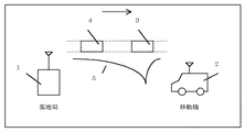
従来、移動体通信において、通信品質向上手段として時間的に複数回数送信処理を行う時間ダイバーシチ技術、連送技術、再送技術が採用されている。図8は、文献「移動体通信の基礎」奥村、進士:電子情報通信学会に記載されている「時間ダイバーシチ」動作を示すものである。
図8において、1は基地局、2は移動局、3および4はバースト、5はフェージング伝送路である。
時間ダイバーシチは複数回数送バーストを送信することによって、通信品質の向上を図っている。基地局1から移動局2に情報を送信するにあたり、いまバースト伝送を想定した場合、バースト3を送信する。
【0003】
そして、ある時間経過後、同じバースト4を再度送信する。移動機2は、バースト3とバースト4両方を受信することにより、通信品質向上を図る。特に図8のフェージング伝送路5のような場合、バースト3受信時、フェージングによる受信電界強度の落ち込みによってバースト3が受信できなかった場合でも、良好な伝送路状態時にバースト4を受信することによって、通信品質を向上することが可能になる。特に、2つのバーストの送信間隔を、フェージングの時間相関が小さくなる時間間隔以上離すことで、効果は増大する。
【0004】
図9は、再送技術を説明したものである。図9において、基地局1からバースト3が移動局2に送信される。回線状態が悪い等の原因により移動局2がバースト3の受信に失敗した場合、移動局2は受信が失敗したことを連絡するためにNACK信号を基地局1に送信する。次に基地局1は、NACK信号を受信して、移動局2がバースト3の受信に失敗したことを認識し、同じ情報をバースト4として再送信する。移動局2がバースト4を受信できた場合は、ACK信号を基地局1に送信する。基地局1は、ACK信号より移動局2がバースト4を受信できたことを認識し、次の新しい情報の送信を開始する。このような再送技術により通信品質の向上が図れる。特にフェージング伝送路において、再送間隔をフェージングの時間相関が小さくなる間隔以上に設定することで、効果は増大する。
【0005】
さらに、同じ情報のバーストを連続して送信する連送技術によって、通信品質を向上することもできる。いずれの場合も、時間的に複数回数同じバーストを送信することにより通信品質の向上が期待できる。しかし、フェージング伝送路において効果を向上しようとすると、送信間隔をフェージングの時間相関が小さくなる時間以上離す必要があり、フェージング変動がゆっくりな場合や、伝送するビットレートが高い場合などは、必要以上に送信間隔をあける必要があったり、送信間隔を短く設定した場合には十分な効果が得られなかった。
【0006】
【発明が解決しようとする課題】
このように、時間的に複数回数送信する時間ダイバーシチ技術、再送技術、連送技術を採用した場合、時間変動の遅い(ドップラー周波数の遅い)フェージング伝送路や伝送速度が高い場合は、伝送路の状態がほぼ同じであるため、十分な効果が得られないという問題があった。例えば、1つめのバーストをフェージングより劣悪な伝送路状態で送信した場合、フェージングのドップラー周波数が遅かったり、伝送速度が速いときは、2つめのバーストを送信する時の伝送路状態がほぼ同じなため、十分な効果が得られないという問題があった。また、効果を得るために時間間隔を十分にあけると、本来、再送や連送に必要な時間間隔以上あける必要が生じ、回線効率が落ちるという問題が生じてしまう。
【0007】
この発明は上記のような欠点を解決するためになされたもので、時間的に複数回数送信するシステムで、低速フェージング伝送路環境および高い伝送速度環境においても、必要以上に時間間隔を離さずに、時間間隔を離した場合とほぼ同様な効果を得ることを目的とする。
【0008】
【課題を解決するための手段】
第1の発明に係わる移動体通信システムは、基地局から移動局へ時間的に複数回数同じバーストデータを送信する移動体通信システムにおいて、
上記基地局は、
送信するバーストデ−タを所定の時間間隔を置いてインタ−リ−ブ処理する第1から第nのインタ−リ−バと、
この第1のインタ−リ−バから第nのインタ−リ−バの出力のいずれを送信するか選択する選択回路と、
選択した上記選択回路からの信号をマルチキャリア変調し出力するマルチキャリア変調回路と、
このマルチキャリア変調回路の出力を送信する送信手段とを有し、
上記移動局は、
受信信号をマルチキャリア復調方式で復調したバーストデ−タを出力するマルチキャリア復調回路と、
このマルチキャリア復調回路からのバーストデ−タを所定の時間間隔を置いてデインタ−リ−ブ処理する、第1から第nのデインタ−リ−バと、
この第1から第nのデインタ−リ−バの出力のいずれを受信するかを選択する選択回路と、
この選択回路が選択したデインタ−リ−バのデータを出力する出力手段とを有するものである。
【0009】
第2の発明に係わる移動体通信システムは、移動局の、第1から第nのデインタ−リ−バが複数のデインタ−リ−ブ処理後、各出力をダイバ−シチ合成するものである。
【0010】
第3の発明に係わる移動体通信システムは、基地局のバースト単位で送信するアンテナを切り替えるものである。
【0011】
第4の発明に係わる移動体通信システムは、基地局の変調回路がマルチキャリア変調方式の直交周波数分割多重化変調方式で復調し、
上記移動局の復調回路がマルチキャリア復調方式の直交周波数分割多重化復調方式で復調するものである。
【0012】
【発明の実施の形態】
実施の形態1.
図1は第1の発明を示すブロック図である。基地局10は、本発明の変調部11を含み、変調部11で変調処理された信号は基地局10より送信される。基地局10は、第1のバースト信号14を送信したあと、第2のバースト信号15を送信する。移動局12は本発明の復調部13を含み、基地局10で送信された信号は、移動局12で受信され、復調部13で復調処理を行う。
【0013】
図2は、変調部11の構成を示すブロック図であり、送信されるデータ系列(通常、誤り訂正符号化処理出力データ系列)は、入力端子20からスイッチ21に入力される。スイッチ21は、送信するバースト単位で出力先が切り替わるもので、後述するスイッチ24と連動する。なお、ここでは簡単のためスイッチ21の出力先数は2としている。第1のバースト信号14を送信する場合、スイッチ21は、第1のインターリーバ22に入力され、第1のインターリーブ処理を施される。そして、スイッチ24を通ってマルチキャリア変調器25でマルチキャリア変調され、出力端子26から外部へ出力される。第2のバースト信号15を送信する場合は、スイッチ21、24は反対側に設定され、第2のインターリーブ処理が施される。ここで、第1のインターリーブ処理と第2のインターリーブ処理は直交、あるいは擬似直交している。
【0014】
図3は、復調部13の構成を示すブロック図であり、受信された信号は、入力端子30を通ってマルチキャリア復調器31で復調処理される。そして、スイッチ32を通って、デインターリーブ処理が施される。スイッチ32は後述するスイッチ35と連動する。なお、第1のバースト14を受信した場合は、第1のデインターリーブ部33に入力され、第2のバースト15を受信した場合は、第2のデインターリーブ部34に入力され。そして、スイッチ35、出力端子36を通って出力される。出力端子36の出力信号は、通常、誤り訂正復号処理が施される。
【0015】
次に動作について説明する。いま簡単のため2つのバーストを連続して送信する2連送処理を想定する。基地局10は、第1のバースト14を移動局12に送信する。第1のバースト信号14は、第1のインターリーバ22によって第1のインターリーブ処理が施されている。次に、基地局10は、第2のバースト15を移動局12に送信する。第2のバースト15は第2のインターリーブ処理が施されている。
【0016】
また、本発明では、マルチキャリア変調器25、マルチキャリア復調器31において、マルチキャリア変復調方式が採用されているが、本実施の形態においては、マルチキャリア変復調方式の1つである、直交周波数分割多重化(OFDM : Orthogonal Frequency Division Multiplexing)変復調方式を想定する。OFDM変復調方式に関しては、文献:「OFDM変復調方式」都竹、電子情報通信学会誌 Vol.79 No.8 pp.831-834 (1996年8月)に記載がある。いま8波のサブキャリア変調を想定した場合の周波数スペクトルを図4に示す。
【0017】
図5は、第1のバースト14と第2のバースト15の周波数スペクトルとインターリーブされた8ビットのデータビットの一例を示したものであり、図5(a)は、第1のインターリーバ22とマルチキャリア変調器25を通った場合の出力を示し、図5(b)は、第2のインターリーバ23とマルチキャリア変調器25を通った場合の出力を示す。このように第1のバースト14と第2のバースト15とでは、送信されるデータビットは(1−8)と同様だが、異なるインターリーブ処理が施されている。いま、第1のバースト14と第2のバースト15が図5(c)に示される周波数選択性フェージング伝送路を通過するとする。
【0018】
この場合、8波のサブキャリアの中心の2つが受信不可能となるが、第1のインターリーブ処理の場合は、4,5の2ビットが受信不可能となるが、第2のインターリーブ処理の場合は、3,6の2ビットが受信不可能となる。これら両方の信号は、デインターリーブ処理後は、1−8の順番に並びかえられるが、第1のバースト14時は誤ったビットが連続となり(4,5),第2のバースト15時は連続しない2ビット(3,6)となって、異なる誤りパターンとなる。この異なる誤りパターン出力を誤り訂正復号処理した場合、復号後の誤り率は異なり、この結果、2つのバースト送信時の伝送路状態が同じでも、良好な通信品質が確保できる。
【0019】
以上のように、時間的に複数のバースト伝送する場合に、マルチキャリア変調方式を採用し、バースト毎にインターリーブ処理を変更することで、バースト送信間隔が短く伝送路環境が十分変動していなくとも、良好な通信品質が得られる。
【0020】
実施の形態2.
図6は、実施の形態2を示すブロック図で、40は、第1のデインターリーバ33と第2のデインターリーバ34出力を合成するダイバーシチ合成部、41はその出力を外部へ出力する出力端子である。図5(a)(b)のようなインターリーブ処理を施し、図5(c)のような周波数選択性フェージング伝送路を通った場合でも、デインターリーブ処理後にダイバーシチ合成することで、周波数ダイバーシチ効果を得ることができ、良好な通信品質を得ることができる。
【0021】
実施の形態3.
図7は、実施の形態3を示すブロック図で、50は、送信バースト単位で切り替わるスイッチ、51は第1の送信アンテナ、52は第2の送信アンテナを示す。ここで、相2つの送信アンテナ51、52は、空間ダイバーシチ利得が十分得られるように間隔が取られているものとする。このようにすることで、インターリーブによる利得と空間ダイバーシチによる利得を得ることが可能になり、良好な通信品質が得られる。
【図面の簡単な説明】
【図1】 実施の形態1によるブロック図である。
【図2】 変調部の構成を示すブロック図である。
【図3】 復調部の構成を示すブロック図である。
【図4】 8波のサブキャリア変調を想定した場合の周波数スペクトラムを示す図である。
【図5】 2つのバースト周波数スペクトラムとインタリーブされた8ビットのデータビットの一例を示す図である。
【図6】 実施の形態2によるブロック図である。
【図7】 実施の形態3によるブロック図である。
【図8】 従来例による時間ダイバーシチの動作を示す。
【図9】 従来例による送信データが受信失敗したときの、再送するシーケンスを示す図である。
【符号の説明】
5 フェージング伝送路
10 基地局
11 変調部
12 移動局
13 復調部
14 第1のバースト信号
15 第2のバースト信号
20 入力端子
21 スイッチ
22 第1のインターリーバ
23 第2のインターリーバ
24 スイッチ
25 マルチキャリア変調器
26 出力端子
30 入力端子
31 マルチキャリア復調器
32 スイッチ
33 第1のデインターリーバ部
34 第2のデインターリーバ部
35 スイッチ
36 出力端子
40 ダイバーシチ合成部
41 出力端子
50 スイッチ
51 第1の送信アンテナ
52 第2の送信アンテナ[0001]
BACKGROUND OF THE INVENTION
The present invention relates to a mobile communication system.
[0002]
[Prior art]
Conventionally, in mobile communication, time diversity technology, continuous transmission technology, and retransmission technology for performing transmission processing a plurality of times in time have been employed as means for improving communication quality. FIG. 8 shows the “time diversity” operation described in the document “Basics of Mobile Communication” Okumura, Shinji: The Institute of Electronics, Information and Communication Engineers.
In FIG. 8, 1 is a base station, 2 is a mobile station, 3 and 4 are bursts, and 5 is a fading transmission path.
Time diversity aims to improve communication quality by transmitting multiple transmission bursts. In transmitting information from the
[0003]
Then, after a certain period of time, the
[0004]
FIG. 9 explains the retransmission technique. In FIG. 9,
[0005]
Further, communication quality can be improved by continuous transmission technology that continuously transmits bursts of the same information. In any case, improvement in communication quality can be expected by transmitting the same burst multiple times in time. However, in order to improve the effect in the fading transmission path, it is necessary to separate the transmission interval more than the time when the time correlation of fading is small, and when the fading fluctuation is slow or the transmission bit rate is high, it is more than necessary. When the transmission interval needs to be increased or the transmission interval is set to be short, a sufficient effect cannot be obtained.
[0006]
[Problems to be solved by the invention]
In this way, when adopting time diversity technology, retransmission technology, continuous transmission technology that transmits multiple times in time, fading transmission line with slow time fluctuation (slow Doppler frequency) or high transmission speed, Since the states are almost the same, there is a problem that a sufficient effect cannot be obtained. For example, when the first burst is transmitted in a transmission path state worse than fading, when the fading Doppler frequency is slow or the transmission speed is high, the transmission path condition when transmitting the second burst is almost the same. Therefore, there was a problem that a sufficient effect could not be obtained. Further, if a sufficient time interval is provided in order to obtain the effect, it is necessary to leave a time interval that is originally necessary for retransmission and continuous transmission, resulting in a problem that the line efficiency is lowered.
[0007]
The present invention has been made to solve the above-described drawbacks, and is a system that transmits a plurality of times in time, and in a low-speed fading transmission path environment and a high transmission speed environment, the time interval is not unnecessarily separated. The purpose is to obtain substantially the same effect as when the time interval is separated.
[0008]
[Means for Solving the Problems]
A mobile communication system according to a first invention is a mobile communication system that transmits the same burst data multiple times in time from a base station to a mobile station.
The base station
First to n-th interleavers for interleaving the burst data to be transmitted at predetermined time intervals;
A selection circuit for selecting which of the outputs from the first interleaver to the nth interleaver is transmitted;
A multicarrier modulation circuit that multicarrier modulates and outputs a signal from the selected selection circuit;
Transmission means for transmitting the output of the multicarrier modulation circuit,
The mobile station
A multicarrier demodulation circuit for outputting burst data obtained by demodulating a received signal by a multicarrier demodulation method;
First to nth deinterleavers for deinterleaving the burst data from the multicarrier demodulator circuit at predetermined time intervals;
A selection circuit for selecting which of the outputs of the first to nth deinterleaver is received;
The selection circuit has output means for outputting data of the deinterleaver selected.
[0009]
In the mobile communication system according to the second aspect of the present invention, after the first to nth deinterleavers of the mobile station perform a plurality of deinterleave processes, the outputs are diversity combined.
[0010]
The mobile communication system according to the third invention switches the antenna to be transmitted in units of bursts of the base station.
[0011]
In the mobile communication system according to the fourth invention, the modulation circuit of the base station demodulates by the orthogonal frequency division multiplexing modulation method of the multicarrier modulation method,
The demodulating circuit of the mobile station demodulates by the orthogonal frequency division multiplexing demodulation method of the multicarrier demodulation method.
[0012]
DETAILED DESCRIPTION OF THE INVENTION
FIG. 1 is a block diagram showing the first invention. The
[0013]
FIG. 2 is a block diagram showing a configuration of the modulation unit 11, and a transmitted data sequence (usually an error correction coding process output data sequence) is input from the
[0014]
FIG. 3 is a block diagram showing the configuration of the
[0015]
Next, the operation will be described. For the sake of simplicity, a two-continuous transmission process for continuously transmitting two bursts is assumed. The
[0016]
In the present invention, the multicarrier modulation / demodulation method is adopted in the
[0017]
FIG. 5 shows an example of 8-bit data bits interleaved with the frequency spectrums of the first burst 14 and the
[0018]
In this case, two of the centers of the 8-wave subcarriers cannot be received, but in the case of the first interleave processing, two
[0019]
As described above, when transmitting multiple bursts in time, adopting the multi-carrier modulation method and changing the interleaving process for each burst, the burst transmission interval is short and the transmission path environment does not fluctuate sufficiently. Good communication quality can be obtained.
[0020]
FIG. 6 is a block diagram showing the second embodiment. 40 is a diversity combining unit that combines the outputs of the
[0021]
FIG. 7 is a block diagram showing the third embodiment, in which 50 is a switch that switches in units of transmission bursts, 51 is a first transmission antenna, and 52 is a second transmission antenna. Here, it is assumed that the two
[Brief description of the drawings]
FIG. 1 is a block diagram according to a first embodiment.
FIG. 2 is a block diagram illustrating a configuration of a modulation unit.
FIG. 3 is a block diagram illustrating a configuration of a demodulation unit.
FIG. 4 is a diagram showing a frequency spectrum when assuming 8-wave subcarrier modulation.
FIG. 5 is a diagram illustrating an example of 8-bit data bits interleaved with two burst frequency spectra;
FIG. 6 is a block diagram according to a second embodiment.
FIG. 7 is a block diagram according to a third embodiment.
FIG. 8 shows a time diversity operation according to a conventional example.
FIG. 9 is a diagram illustrating a retransmission sequence when transmission data according to a conventional example fails to be received.
[Explanation of symbols]
5 Fading
Claims (7)
上記基地局は、
送信するバーストデ−タを所定の時間間隔を置いてインタ−リ−ブ処理する第1から第nのインタ−リ−バと、
この第1のインタ−リ−バから第nのインタ−リ−バの出力のいずれを送信するか選択する選択回路と、
選択した上記選択回路からの信号をマルチキャリア変調し出力するマルチキャリア変調回路と、
マルチキャリア変調回路の出力を送信する送信手段とを有し、
上記移動局は、
受信信号をマルチキャリア復調方式で復調したバーストデ−タを出力するマルチキャリア復調回路と、
このマルチキャリア復調回路からのバーストデ−タを所定の時間間隔を置いてデインタ−リ−ブ処理する、第1から第nのデインタ−リ−バと、
上記第1から第nのデインタ−リ−バが複数のデインタ−リ−ブ処理後、各出力をダイバ−シチ合成するダイバーシチ合成手段と、
このダイバーシチ合成手段の出力を出力する出力手段と
を有することを特徴とする移動体通信システム。In a mobile communication system that transmits the same burst data multiple times in time from a base station to a mobile station,
The base station
First to n-th interleavers for interleaving the burst data to be transmitted at predetermined time intervals;
A selection circuit for selecting which of the outputs from the first interleaver to the nth interleaver is transmitted;
A multicarrier modulation circuit that multicarrier modulates and outputs a signal from the selected selection circuit;
Transmission means for transmitting the output of the multicarrier modulation circuit,
The mobile station
A multicarrier demodulation circuit for outputting burst data obtained by demodulating a received signal by a multicarrier demodulation method;
First to nth deinterleavers for deinterleaving the burst data from the multicarrier demodulator circuit at predetermined time intervals;
Diversity combining means for diversity combining the respective outputs after the first to nth deinterleaver performs a plurality of deinterleave processing;
A mobile communication system comprising output means for outputting the output of the diversity combining means .
上記基地局は、
送信するバーストデ−タを所定の時間間隔を置いてインタ−リ−ブ処理する第1から第nのインタ−リ−バと、
この第1のインタ−リ−バから第nのインタ−リ−バの出力のいずれを送信するか選択する選択回路と、
選択した上記選択回路からの信号をマルチキャリア変調し出力するマルチキャリア変調回路と、
マルチキャリア変調回路の出力を送信するアンテナおよびバースト単位で送信する上記アンテナを切り替えるスイッチを含む送信手段とを有し、
上記移動局は、
受信信号をマルチキャリア復調方式で復調したバーストデ−タを出力するマルチキャリア復調回路と、
このマルチキャリア復調回路からのバーストデ−タを所定の時間間隔を置いてデインタ−リ−ブ処理する、第1から第nのデインタ−リ−バと、
この第1から第nのデインタ−リ−バの出力のいずれを受信するかを選択する選択回路と、
この選択回路が選択したデインタ−リ−バのデータを出力する出力手段とを有することを特徴とする移動体通信システム。In a mobile communication system that transmits the same burst data multiple times in time from a base station to a mobile station,
The base station
First to n-th interleavers for interleaving the burst data to be transmitted at predetermined time intervals;
A selection circuit for selecting which of the outputs from the first interleaver to the nth interleaver is transmitted;
A multicarrier modulation circuit that multicarrier modulates and outputs a signal from the selected selection circuit;
A transmission means including an antenna for transmitting the output of the multicarrier modulation circuit and a switch for switching the antenna for transmission in burst units ;
The mobile station
A multicarrier demodulation circuit for outputting burst data obtained by demodulating a received signal by a multicarrier demodulation method;
First to nth deinterleavers for deinterleaving the burst data from the multicarrier demodulator circuit at predetermined time intervals;
A selection circuit for selecting which of the outputs of the first to nth deinterleaver is received;
A mobile communication system comprising: output means for outputting data of a deinterleaver selected by the selection circuit.
上記移動局は、上記復調回路がマルチキャリア復調方式の直交周波数分割多重化復調方式で復調することを特徴とする請求項1または2に記載の移動体通信システム。In the base station, the modulation circuit modulates with a multi-carrier modulation orthogonal frequency division multiplexing modulation scheme,
3. The mobile communication system according to claim 1, wherein the demodulating circuit demodulates the mobile station using an orthogonal frequency division multiplexing demodulating system of a multicarrier demodulating system.
送信するバーストデ−タを所定の時間間隔を置いてインタ−リ−ブ処理する第1から第nのインタ−リ−バと、 First to n-th interleavers for interleaving the burst data to be transmitted at predetermined time intervals;
この第1のインタ−リ−バから第nのインタ−リ−バの出力のいずれを送信するか選択する選択回路と、 A selection circuit for selecting which of the outputs from the first interleaver to the nth interleaver is transmitted;
選択した上記選択回路からの信号をマルチキャリア変調し出力するマルチキャリア変調回路と、 A multicarrier modulation circuit that multicarrier modulates and outputs a signal from the selected selection circuit;
マルチキャリア変調回路の出力を送信するアンテナおよびバースト単位で上記アンテナを切り替えるスイッチを含む送信手段と、 Transmitting means including an antenna for transmitting the output of the multicarrier modulation circuit and a switch for switching the antenna in units of bursts;
を有することを特徴とする基地局。A base station characterized by comprising:
上記基地局が送信するバーストデ−タを所定の時間間隔を置いて第1から第nのインターリーバでインタ−リ−ブ処理し上記第1から第nのインターリーバの出力から選択した信号をマルチキャリア変調して送信した信号、を受信信号として受信する受信手段と、 The burst data transmitted by the base station is interleaved by first to n-th interleavers at predetermined time intervals, and a signal selected from the outputs of the first to n-th interleavers is multiplexed. Receiving means for receiving a signal modulated and transmitted as a received signal;
上記受信信号をマルチキャリア復調方式で復調したバーストデ−タを出力するマルチキャリア復調回路と、 A multicarrier demodulation circuit for outputting burst data obtained by demodulating the received signal by a multicarrier demodulation method;
このマルチキャリア復調回路からのバーストデ−タを所定の時間間隔を置いてデインタ−リ−ブ処理する第1から第nのデインタ−リ−バと、 First to n-th deinterleavers for deinterleaving the burst data from the multicarrier demodulation circuit at predetermined time intervals;
上記第1から第nのデインタ−リ−バが複数のデインタ−リ−ブ処理後、各出力をダイバ−シチ合成するダイバーシチ合成手段と、 Diversity combining means for diversity combining the respective outputs after the first to nth deinterleaver performs a plurality of deinterleave processing;
このダイバーシチ合成手段の出力を出力する出力手段と Output means for outputting the output of the diversity combining means;
を有することを特徴とする移動局。A mobile station characterized by comprising:
Priority Applications (1)
| Application Number | Priority Date | Filing Date | Title |
|---|---|---|---|
| JP07505599A JP4161455B2 (en) | 1999-03-19 | 1999-03-19 | Mobile communication system |
Applications Claiming Priority (1)
| Application Number | Priority Date | Filing Date | Title |
|---|---|---|---|
| JP07505599A JP4161455B2 (en) | 1999-03-19 | 1999-03-19 | Mobile communication system |
Publications (2)
| Publication Number | Publication Date |
|---|---|
| JP2000269929A JP2000269929A (en) | 2000-09-29 |
| JP4161455B2 true JP4161455B2 (en) | 2008-10-08 |
Family
ID=13565147
Family Applications (1)
| Application Number | Title | Priority Date | Filing Date |
|---|---|---|---|
| JP07505599A Expired - Fee Related JP4161455B2 (en) | 1999-03-19 | 1999-03-19 | Mobile communication system |
Country Status (1)
| Country | Link |
|---|---|
| JP (1) | JP4161455B2 (en) |
Families Citing this family (11)
| Publication number | Priority date | Publication date | Assignee | Title |
|---|---|---|---|---|
| JP3801460B2 (en) | 2001-04-19 | 2006-07-26 | 松下電器産業株式会社 | Base station apparatus and wireless communication method |
| JP3679759B2 (en) | 2002-01-17 | 2005-08-03 | 松下電器産業株式会社 | Wireless transmission device |
| WO2003088537A1 (en) | 2002-04-12 | 2003-10-23 | Matsushita Electric Industrial Co., Ltd. | Multi-carrier communication device and multi-carrier communication method |
| US7039370B2 (en) | 2003-10-16 | 2006-05-02 | Flarion Technologies, Inc. | Methods and apparatus of providing transmit and/or receive diversity with multiple antennas in wireless communication systems |
| KR100876757B1 (en) | 2003-10-31 | 2009-01-07 | 삼성전자주식회사 | System and method for consturcting sub channel in a communication system |
| US7457384B2 (en) | 2004-09-28 | 2008-11-25 | Sanyo Electric Co., Ltd. | Diversity method and apparatus, and receiving method and apparatus |
| JP4152370B2 (en) * | 2004-09-28 | 2008-09-17 | 三洋電機株式会社 | Diversity method and apparatus |
| JP4824016B2 (en) | 2005-03-15 | 2011-11-24 | 富士通株式会社 | Communication apparatus and communication method |
| US7978635B2 (en) | 2007-03-21 | 2011-07-12 | Qualcomm Incorporated | H-ARQ acknowledgment detection validation by re-decoding |
| JP4898727B2 (en) * | 2008-03-17 | 2012-03-21 | パナソニック株式会社 | TRANSMISSION DEVICE, RECEPTION DEVICE, TRANSMISSION METHOD, AND RECEPTION METHOD |
| JP5654558B2 (en) * | 2010-02-19 | 2015-01-14 | パナソニックIpマネジメント株式会社 | Transceiver |
Family Cites Families (11)
| Publication number | Priority date | Publication date | Assignee | Title |
|---|---|---|---|---|
| US5230082A (en) * | 1990-08-16 | 1993-07-20 | Telefonaktiebolaget L M Ericsson | Method and apparatus for enhancing signalling reliability in a cellular mobile radio telephone system |
| JPH0758682A (en) * | 1993-08-16 | 1995-03-03 | N T T Idou Tsuushinmou Kk | Mobile radio base station |
| JP2778498B2 (en) * | 1995-01-11 | 1998-07-23 | 日本電気株式会社 | Spread spectrum diversity transceiver |
| EP0740437A1 (en) * | 1995-04-28 | 1996-10-30 | Koninklijke Philips Electronics N.V. | Hardware-efficient frequency de-interleaving |
| JPH08321785A (en) * | 1995-05-24 | 1996-12-03 | Sony Corp | Transmitter, receiver, transmission method, reception method and transmission method |
| JPH0923212A (en) * | 1995-07-07 | 1997-01-21 | Hitachi Ltd | Digital mobile radio data transmitter and transmission system |
| JPH09321682A (en) * | 1996-05-27 | 1997-12-12 | Sony Corp | Communication system, communication method and terminal equipment |
| JP3019147B2 (en) * | 1996-10-28 | 2000-03-13 | 日本電気株式会社 | Transmit diversity device |
| JP3722969B2 (en) * | 1998-01-08 | 2005-11-30 | 株式会社東芝 | Retransmission control method and retransmission control apparatus |
| JPH11215091A (en) * | 1998-01-22 | 1999-08-06 | Toshiba Corp | Ofdm signal transmission method and ofdm signal transmitter thereof |
| JP3576787B2 (en) * | 1998-01-22 | 2004-10-13 | 株式会社東芝 | OFDM signal transmitting / receiving method, OFDM signal transmitting / receiving apparatus, OFDM signal transmitting method, and OFDM signal transmitting apparatus |
-
1999
- 1999-03-19 JP JP07505599A patent/JP4161455B2/en not_active Expired - Fee Related
Also Published As
| Publication number | Publication date |
|---|---|
| JP2000269929A (en) | 2000-09-29 |
Similar Documents
| Publication | Publication Date | Title |
|---|---|---|
| US6950474B1 (en) | OFDM communication device | |
| US9749167B2 (en) | Transmitting apparatus and transmitting method | |
| KR101242592B1 (en) | Radio parameter group generating apparatus, transmitter and receiver | |
| KR100754191B1 (en) | Improved interleaver and parser for OFDM MIMO systems | |
| KR101710616B1 (en) | Signaling and channel estimation for uplink transmit diversity | |
| US7684362B2 (en) | MIMO multiple transmission device and method | |
| KR101304833B1 (en) | Apparatus and method for mapping/demapping according to rs power assignment in mobile communication system | |
| CA2694514C (en) | Transmit methods for ccfi/pcfich in a wireless communication system | |
| US20060107171A1 (en) | Interleaver and de-interleaver systems | |
| EP0744841A2 (en) | Method and apparatus for transmission and reception of burst signals using time diversity and antenna switching | |
| EP1938538B1 (en) | Method for variable sub-carrier mapping and device using the same | |
| US20060212773A1 (en) | Ultrawideband architecture | |
| JP2003309535A (en) | Multicarrier transmitter, multicarrier receiver, and multicarrier transmitting method | |
| KR100584439B1 (en) | Apparatus and method for interference cancellation of ofdm system using multiple antenna | |
| JP4161455B2 (en) | Mobile communication system | |
| JP3746029B2 (en) | Wireless communication apparatus and wireless communication method | |
| EP1036438B1 (en) | Method and apparatus for obtaining transmit diversity using switched antennas | |
| US7397862B2 (en) | Method of designing interleavers for multiple-encoder MIMO OFDM systems | |
| US20060195756A1 (en) | Radio transmitter apparatus, radio receiver apparatus, and radio transmission method | |
| JPH11136180A (en) | Data communication method, transmitter and cellular radio communication system | |
| JP4169796B2 (en) | Wireless communication system | |
| WO2001017148A1 (en) | Ofdm communication device | |
| KR20060086673A (en) | Transmitter and receiver in dblast system | |
| WO2006076787A1 (en) | Method and system for retransmitting data packets | |
| US9565004B2 (en) | Transmit diversity for pre-coded radio control signals |
Legal Events
| Date | Code | Title | Description |
|---|---|---|---|
| RD01 | Notification of change of attorney |
Free format text: JAPANESE INTERMEDIATE CODE: A7421 Effective date: 20040624 |
|
| A621 | Written request for application examination |
Free format text: JAPANESE INTERMEDIATE CODE: A621 Effective date: 20051222 |
|
| A977 | Report on retrieval |
Free format text: JAPANESE INTERMEDIATE CODE: A971007 Effective date: 20080327 |
|
| A131 | Notification of reasons for refusal |
Free format text: JAPANESE INTERMEDIATE CODE: A131 Effective date: 20080408 |
|
| A521 | Written amendment |
Free format text: JAPANESE INTERMEDIATE CODE: A523 Effective date: 20080605 |
|
| TRDD | Decision of grant or rejection written | ||
| A01 | Written decision to grant a patent or to grant a registration (utility model) |
Free format text: JAPANESE INTERMEDIATE CODE: A01 Effective date: 20080701 |
|
| A01 | Written decision to grant a patent or to grant a registration (utility model) |
Free format text: JAPANESE INTERMEDIATE CODE: A01 |
|
| A61 | First payment of annual fees (during grant procedure) |
Free format text: JAPANESE INTERMEDIATE CODE: A61 Effective date: 20080714 |
|
| FPAY | Renewal fee payment (event date is renewal date of database) |
Free format text: PAYMENT UNTIL: 20110801 Year of fee payment: 3 |
|
| FPAY | Renewal fee payment (event date is renewal date of database) |
Free format text: PAYMENT UNTIL: 20110801 Year of fee payment: 3 |
|
| FPAY | Renewal fee payment (event date is renewal date of database) |
Free format text: PAYMENT UNTIL: 20110801 Year of fee payment: 3 |
|
| FPAY | Renewal fee payment (event date is renewal date of database) |
Free format text: PAYMENT UNTIL: 20120801 Year of fee payment: 4 |
|
| FPAY | Renewal fee payment (event date is renewal date of database) |
Free format text: PAYMENT UNTIL: 20120801 Year of fee payment: 4 |
|
| FPAY | Renewal fee payment (event date is renewal date of database) |
Free format text: PAYMENT UNTIL: 20130801 Year of fee payment: 5 |
|
| LAPS | Cancellation because of no payment of annual fees |