JP4159912B2 - Color conversion method with hue correction using multiple lookup tables and interpolation - Google Patents
Color conversion method with hue correction using multiple lookup tables and interpolation Download PDFInfo
- Publication number
- JP4159912B2 JP4159912B2 JP2003083933A JP2003083933A JP4159912B2 JP 4159912 B2 JP4159912 B2 JP 4159912B2 JP 2003083933 A JP2003083933 A JP 2003083933A JP 2003083933 A JP2003083933 A JP 2003083933A JP 4159912 B2 JP4159912 B2 JP 4159912B2
- Authority
- JP
- Japan
- Prior art keywords
- color
- signal
- cmy
- cmyk
- rgb
- Prior art date
- Legal status (The legal status is an assumption and is not a legal conclusion. Google has not performed a legal analysis and makes no representation as to the accuracy of the status listed.)
- Expired - Fee Related
Links
Images


Landscapes
- Color, Gradation (AREA)
- Image Processing (AREA)
- Facsimile Image Signal Circuits (AREA)
- Color Image Communication Systems (AREA)
Description
(関連出願)
本願は、2000年12月19日に出願された米国特許出願第09/741,458号、「複数のルックアップテーブルと補間とを用いたCMYKカラープリンタのためのブラック生成方法」に関連している。
【0001】
(発明分野)
本発明はデジタル画像の色変換の分野に属し、特にRGB入力信号を、シアン(C)・マゼンタ(M)・イエロー(Y)・ブラック(K)という4つの色素を備えたプリンタに対応するCMYKプリンタ信号へと変換する方法を対象とし、また、LCDディスプレイの色補正といった一般的な色変換方法を対象とする。
【0002】
(発明の背景)
カラー印刷装置には、CMYK色素と総称される、シアン(C)・マゼンタ(M)・イエロー(Y)・ブラック(K)という4つの色素を使用するものが多い。CMYK出力装置では、CMYK色素の1つ以上の組み合わせによって、多くの色彩を生成する事ができる。CMYK装置がRGB装置として設計される場合には、RGBの各組み合わせから、CMYKに固有の組み合わせを形成する必要がある。
【0003】
これら固有の組み合わせを計算するために従来用いられてきたのが、下色除去(UCR)技術やグレー成分置換(GCR)技術である。これらの技術は簡単に実装できるが、K色素の追加によって利用可能になる色域を十分に活用することができない。
【0004】
一方、所望の組み合わせを求めてCMYK信号空間全体をサーチする他の強力な技術からは良好な成果が得られるが、リアルタイムでのインプリメンテーション(実行)には適していない。
【0005】
CMY色素に加えてK色素を使用すると、数多くの効果がある。例えば濃い黒色や微妙な陰影が得られたり、中間色バランスのコントロールが簡単になったりする。カラー管理に適したCMYKプリンタの概略は次の通りである。すなわち、CIELAB又はsRGBのような測色空間で特定された色を再現するために、C,Y,M,K色素の組み合わせを計算する。前述のように、幾つかの色は複数のCMYKの組み合わせによって再現される。
【0006】
UCR及びGCR技術では、まずRGB信号が変換されて、公称CMY信号が得られる。それから、CMY色素の配合に基づき、一定量のCMY色素の代わりにK色素が使用される。使用されるK色素の量と、除去されるCMY色素の量とはふつう、C,M,Yの最小入力量に左右される。通常のインプリメンテーションでは、1本のブラック生成(BG)曲線と3本のUCR曲線とが用いられる。これらの曲線は1次元LUTs(ルックアップテーブル)としてインプリメント(実行)され、そこでは、ルックアップテーブルへのインデックスとしてCMY信号の最小値が使用される。これは公称RGB信号をプリンタCMYK信号へと変換するモデルを提供する。
【0007】
こうしたモデルを備えていれば、そのプリンタはRGBプリンタであると考えられる。RGBプリンタでは、色域内の全ての色について、RGB信号と測色空間で特定される色とが1対1関係で対応する。
【0008】
RGBプリンタの概略は次の通りである。RGB入力立方体を広範囲でサンプリングするための、カラーパッチを有するRGBプリンタターゲットが形成され、CIELAB出力数値が測定される。それから測定データに基づいて、測色空間で特定された色をプリンタRGB空間へと変換するプリンタプロファイルが作成される。色域外の色を再現するには、色域マッピング技術が用いられる。RGBプリンタモデルが、プリンタプロファイリング処理のモジュラー設計において極めて有用なのは明白である。
【0009】
こうした技術は、RGBからCMYKへの変換処理の複雑さを表に出さず、もっと直観的なRGB入力色空間をユーザに提供する。また、Windows(登録商標)Graphical Display Interface(GDI)printingのようなアプリケーションもある。こうしたアプリケーションでは、プリンタはRGB装置としてのみアドレス可能であり、RGBプリンタモデルの構築を必要とする。
【0010】
上述の単純なUCR/GCR技術は、特定の色を再現するために「最良の」CMYKの組み合わせを選択するのに十分な柔軟性を提供してくれる訳ではない。CMYK数値の一定の組み合わせを用いる単純な技術は能力が低いため、それを用いて得られるRGBプリンタの色域もまた狭いものになる。
【0011】
CMYKの使用をコントロールするもっと高度な方法としては、所望のCMYK信号を得るために、CMYKプリンタの全色域をサーチするのが一般的である。測色空間で特定される1つの色について考えてみよう。もしも、その色が色域内の色であれば、サーチによって、入力色を再現するCMYK信号ベクトルが1つ以上見つかるだろう。これらのCMYK信号は、使用されるK色素の量(最少量から最大量まで)によって分類される。
【0012】
所望のCMYK信号は、使用されるK色素の相対量を特定する事で得られる。これを行うための1つの方法は、発見されたCMYK信号ベクトルにおける、Kの最少量及び最大量に対するKの使用量を、パラメータを用いて特定することである。このパラメータは、最適の出力画質を得るための入力色空間における位置関数として設定される。これらの方法では、CMYKプリンタ色域が十分活用される。
【0013】
しかし、プリンタCMYK空間全体を広範にサンプリングし、印刷されるターゲットをCIELABのような測色空間において測定し、測色空間で特定された各色域内の色に対応可能なCMYK信号を全て発見するべく補間を行うプリンタターゲットの構築とは、集約的な計算による「強力な」方法である。
【0014】
更に、CMYK出力信号は、RGB信号空間における入力色と関連しておらず、むしろ測色空間の色と関連している。よって、これらの方法に限って、RGBプリンタとしてのCMYKプリンタ設計には使えないのである。
【0015】
これらは測色空間内の各色を、CMYKプリンタ信号に直接変換する3次元カラールックアップテーブルの形成には有用だが、そのルックアップテーブル形成手順には、色域マッピング技術をも組み込む必要があるのは言うまでもない。
【0016】
印刷にブラック(K)色素を用いることで、CMY色素だけを組み合わせて得られるよりも高い濃度が実現する。ここで解決しなくてはならない問題は次の点にある。すなわち、RGB又はCMY入力値に基づいて使用されるブラック色素の量をどのように決定するのか。また、一旦ブラック色素が導入された後に、他の色素をどのように調整するのか。先述の通り先行技術は、この問題の主な解決策を2つ示している。それは、(1)UCRタイプの技術と(2)サーチ技術である。関連する特許出願は、RGB入力信号をCMYK信号に変換する方法の中で、CMY立方体の境界線上及び中心を通る対角線上における複数のブラック生成ルックアップテーブルと、補間とを使用する方法を説明している。
【0017】
米国特許第6,281,984号(Decker他、2001年8月28日付与)「外部から定義された4次元色素(CMYK)を、所定のプリンタに付随した4つのインク(C’M’Y’K’)について定義された対応する4次元色素へと変換するために改善されたシステム、方法、及びプログラム」は、Lab数値のCMYK数値への変換について説明している。
【0018】
米国特許第6,229,580号(Inoue、2001年5月8日付与)「記録されたカラープログラムを有する画像カラー補正装置及び記録媒体」は、特定の色調の色補正と、該特定の色調に関連する複数の色調について説明している。
【0019】
米国特許第6,191,874号(Yamada 他、2001年2月20日付与)「画像処理装置と方法、及び記録媒体」は、無色の色成分の抽出と、無色の色成分の関数としてのCMY信号の処理について説明している。
【0020】
米国特許第6,140,997号(Tanaka、2000年10月31日付与)「RGB色空間を人間の感覚に近い色空間へと変換するための色特性抽出装置及び方法」は、各RGB画素を色相・彩度・明度(HLS)値へと変換することでなされる色処理について説明している。
【0021】
米国特許第6,137,596号(Decker他、2000年10月24日付与)「3次元色素を3次元色素以上に変換するシステム、方法、及びプログラム」と、米国特許第6,137,594号(Decker他、2000年10月24日)「外部から定義された色素(CMYK)を所定のプリンタに付随した対応する色素(C’M’Y’K’)へと変換するためのシステム、方法、及びプログラム」と、米国特許第6,061,501号(Decker他、2000年5月9日付与)「外部から定義された4つの色素(CMYK)を、所定のプリンタに付随した4つのインク(C'M'Y'K')について定義された対応する4次元色素へと変換するシステム、方法、及びプログラム」とは、色空間のカラーパッチをブラック色空間のパッチと結合させて、測定されたLab数値に基づき、カラーポイント値をブラック色空間の関数として変換する事についてそれぞれ説明している。
【0022】
米国特許第6,057,931号(McConnell 他、2000年5月2日付与)「カラー画像複写の制御方法及び装置」は、画素化された画像のHSL数値による色補正について説明している。
【0023】
米国特許第6,039,434号(Moroney、2000年5月21日付与)「サーマルインクジェットプリンタ又はプロッタにおける閾値化された下色除去及びブラック置換」は、RGB信号の減色領域への変換について説明している。
【0024】
米国特許第5,987,168号(Decker他、1999年11月16日付与)「3次元色素を3次元色素以上に変換するためのシステム、方法、及びプログラム」は、3色空間を4色空間に変換するためのルックアップテーブルの形成について説明している。
【0025】
米国特許第5,933,252号(Emori他、1999年8月3日付与)「カラー画像処理方法及びそのための装置」は、色の連続性を維持しながら、広い色空間を狭い色空間へと変換することについて説明している。
【0026】
米国特許第5,894,358号(Ebner 他、1999年4月13日付与)「適用可能な色濃度管理システム」は、全てのトナー適用範囲の加算と選択的なトナー減算とによるUCR技術について説明している。
【0027】
米国特許第5,887,124号(Iwasaki他、1999年3月23日付与)「色成分数値に従って制限処理が実行される画像処理装置及び方法」は、色素の使用を制限する事について説明している。
【0028】
米国特許第5,828,816(Kise他、1998年10月27日付与)「画像処理装置及び画像処理方法」は、青色の再現を改良する技術について説明している。
【0029】
米国特許第5,764,388号(Ueda他、1998年6月9日付与)「カラー信号の変換方法及び装置」は、色空間信号を有色空間及び無色空間成分を有する信号へと変換することについて説明している。
【0030】
米国特許第5,719,689号(Terada、1998年2月17日付与)「画像処理装置」は、グレー成分抽出ユニットを用いて、色空間信号を色空間及びブラック信号へ変換することについて説明している。
【0031】
米国特許第5,717,839号(Ichikawa、1998年2月10日付与)「プリンタに転送された外部ソース用の補正テーブルデータを有する画像処理機及びプリンタ」は、画像入力装置及び画像プリンタに依存して画像を補正するための画像補正ルックアップテーブルを説明している。
【0032】
米国特許第5,615,312号(Kohler, 1997年3月25日付与)「ビジネスグラフィックス表現モードを有するカラー管理システム」は、カラー画像を改善するBGR技術について説明している。
【0033】
米国特許第5,504,821号(Kanamori他、1996年4月2日付与)「容量の小さいメモリを使って、色空間内のカラー画像に3次元色変換を行うための色変換装置」は、ルックアップテーブルと色立方体とを用いて色空間変換を実行する事について説明している。
【0034】
米国特許第5,146,328号(Yamasaki他、1992年9月8日付与)「カラー信号ネットワークシステム」は、多様な入力・出力装置を備えたネットワーク上で適合する出力フォーマットへとカラー信号を変換するシステムについて説明している。
【0035】
米国特許第5,113,248号(Hibi他、1992年5月12日付与)「画像形成装置における色除去のための方法と装置」は、色補正を行うUCRシステムについて説明している。
【0036】
米国特許第4,977,448号(Murata他、1990年12月11日付与)「正確な色再現性能を有するカラー画像処理装置」は、多様な色特性を補正するシステムについて説明している。
【0037】
米国特許第4,965,664号(Udagawa他、1990年10月23日付与)「個別のカラー信号成分を変換することで、入力カラー画像信号からカラー画像を記録するためのカラー画像信号処理方法及び装置」は、輝度・色相・色度(クロマティック、彩度)信号を多様な出力色空間パラダイムへ変換することについて説明している。
【0038】
米国特許第4,908,701号(Udagawa、1990年3月13日付与)「画像処理中の色調節のためのカラー画像処理及び装置」は、暗色ポイントの色成分の関数としての色補正について説明している。
【0039】
米国特許第4,649,423号(Hoffrichter他、1987年 3月10日付与)「色相とカラーの選択的な補正のための方法及び回路調節」は、HSL信号の処理による色分解の補正について説明している。
【0040】
米国特許第4,636,844号(Sasaki、1987年1月13日付与)「カラー画像信号の処理方法」は、色分解の関数としてのブラック信号の処理について説明している。
【0041】
米国特許第4,553,835(Morgan, Jr., 1985年11月19日付与)「印刷前カラー校正刷りの作成手順」は、画像のイエロー含有量の関数として、色分解校正刷りを作成する事について説明している。
【0042】
米国特許第4,500,919(Schreiber、1985年2月19日付与)「カラー複写システム」は、最終的な印刷カラー値を補正するためにCRTの3刺激値を使用することについて説明している。
【0043】
(発明の要約)
色変換方法は、
複数の入力信号を有する第1色領域入力信号セットを用意し、
信号強度に従って第1色領域入力信号セットの入力信号を分類し、
カラー多面体に対応する複数の1次元ルックアップテーブルのセットを設計・形成し、
特定のカラー多面体と共に用いるための1セットのルックアップテーブルを選択し、ここで前記選択は、入力信号セットの関数として確定された多面体の1区分の関数であり、
ルックアップテーブルセット内の数値を、入力信号セットの関数としてルックアップし、
分類された信号強度の関数として重みを生成し、
選択されたルックアップテーブルからの出力値を、選択されたルックアップテーブル及び生成された重みの関数として補間し、所望の色領域信号セットに変換される色領域信号セットを生成することを含む。
【0044】
本発明の目的は、公称RGB信号をプリンタCMYK信号へと変換するためのモデルを提供する事である。
【0045】
本発明の別の目的は、RGB信号からCMYK信号への局部的な変換制御を可能にする色変換方法を提供する事である。
【0046】
本発明の更に別の目的は、複数の1次元LUTs(ルックアップテーブル)を用いてCMYK色素の使用をコントロールする色変換方法を提供する事である。
【0047】
更に別の目的は、入力カラー立方体の中心を通る対角線上及び境界線上において、ルックアップテーブルを使用する色変換方法を提供する事である。
【0048】
更に別の目的は、利用可能なCMYK色域の大部分を使う色変換方法を提供する事である。
【0049】
更に別の目的は、識別可能な色相のずれを補正するための方法を提供する事である。
【0050】
更に別の目的は、ニュートラルなグレースケールと、正確な色相角度と、ブラックから1次色(原色)/ブラックから2次色(原色との混色)へのカラーランプ(色傾斜)における適切な知覚空間とを維持するための方法を提供する事である。
【0051】
更に別の目的は、1次色と2次色に対し色相補正を行う事である。
【0052】
本発明の上記の要約と目的は、本発明の性質を速やかに把握するためのものである。本発明をより徹底的に理解するには、下記の本発明の好ましい実施例を、図面と共に参照して頂きたい。
【0053】
(好ましい具体例の詳細な説明)
本発明の方法には、RGB(レッド・グリーン・ブルー)又はCMY(シアン・マゼンタ・イエロー)信号をCMYK(シアン・マゼンタ・イエロー・ブラック)信号へと変換するための、柔軟性のある計算構造が含まれる。この計算構造は従来の下色除去(UCR)及びグレー成分置換(GCR)技術を発展させたものと見なされるかもしれないが、ここでは複数セットの1次元CMYKルックアップテーブル(LUTs)が用いられて、CMYK色素の使用がコントロールされる。ルックアップテーブルは、入力信号色立方体における、中心を通る対角線上に、かつ境界線上に配置されて効果を上げる。
【0054】
これらのルックアップテーブルを適切に設計することで、利用可能なCMYK色域の大部分を活用し、しかも一定の非理想的な装置の反応(例:ダウンストリーム・ハーフトーニング及びページマーキング処理の結果生じうる、純色からブラック又はホワイトへの直線に沿った色相のずれ)を補正するような、RGBからCMYKへの変換モデルが得られる。例えば、ルックアップテーブルは、各純色からホワイト又はブラックへの各ランプ(ramps)における色相角度が一定になるように制約を受けていてもよい。
【0055】
本発明は、「未処理の」(較正化されていない)出力装置における、最適状態に及ばない色作用の補正という問題を解決する。本発明の方法は、カラー印刷に適用される際に、一般に表示モニター・デジタルカメラ・スキャナで使用されるRGB入力信号を、大多数のカラープリンタ(例:インクジェット又はレーザプリンタ)で使用される相当量のCMYK色素に変換するのに利用される。ここで開示される方法は、LCD表示装置の強力な非線形測色作用の補正にも適用される。後者の場合では、本発明はRGBからCMYKへの変換よりもむしろ、RGBからRGBの変換を計算する。この応用では、計算構造は僅かに異なったものになる。なぜなら、たった3つのチャネルしか計算する必要がなく、それでいて原理は同一だからである。
【0056】
本発明の方法は、非線形RGBからCMYK、RGBからRGB、又はRGBから他の色空間への変換を確定するための効率的な計算構造であり、CMYKプリンタをRGBプリンタとして扱うために用いられる。本発明の方法には、RGB色立方体内に入力されたRGBポイントの位置に基づいて出力信号を得る、効率的なテーブルルックアップ及び補間技術が含まれる。ここでは、この計算構造をCMYKプリンタに適用する際の、本発明の方法の好ましい具体例について説明する。4色以上の色素を使用するカラープリンタ(例えば、Hexachrome TMプリンタ、つまりCMYKに明るいシアン色素と明るいマゼンタ色素を加えたプリンタ)への拡大的適用はごく簡単であり、本発明の方法を理解した当該分野の技術者にとっては十分可能であると考えられる
追加的な背景説明によって、従来のUCR及びGCR技術の簡単なインプリメンテーションを振り返ることにする。本発明の方法はこの簡単なインプリメンテーションを発展させて、出力色素の使用をコントロールするための柔軟性を可能にするような、効率的な計算構造を実現させるものである。
【0057】
(従来のUCR及びGCRインプリメンテーション)
図1に示すように、RGB入力信号空間は概念上、RGB又はCMY色立方体10と見なされる。ブラックポイント12(RGB信号が0)を原点とし、その3つの軸を各々RGBとすると、この立方体はRGB立方体である。或いは、ホワイトポイント14(CMY信号が0)を原点とすると、この立方体はCMY立方体である。つまり、RGB立方体とCMY立方体とは同じ入力信号空間を示している。ここで、RGB及びCMY信号は本来、次の式(1)の関係にある。
【0058】
C=1.0−R, M=1.0−G, Y=1.0−B (1)
ブラック生成(BG)曲線及びUCR曲線の概形は図2(a)で表される。ここには3本のUCR曲線がある(Cは二点鎖線、Mは破線、Yは一点鎖線でそれぞれ示されている)。これらの曲線は通常、互いに僅かに異なるよう形成される。それは入力信号立方体のホワイトからブラックへと、中心を通って伸長する対角線上(図1の直線16)に存在する、視覚的にニュートラルな生成色を得るためである。これらの曲線は1次元ルックアップテーブルとして簡単にインプリメントされ、またルックアップテーブルへのインデックスは、以下の式(2)にて示した、入力されたCMY信号の最小値である、
Ki=min(Ci,Mi,Yi) (2)
任意のCMY入力信号とCMYK出力信号とは、次の等式(3)で得られる。
【0059】
Co=Ci−UCRc(Ki),
Mo=Mi−UCRm(Ki),
Yo=Yi−UCRy(Ki),
Ko=BG(Ki) (3)
ここで、図2(a)の「UCR」及び「BG」は、UCR及びBGの関数を表す。また、式(3)における、下付き添え字の「o」は出力、下付き添え字の「i」は入力を表す。
【0060】
等式(3)と図2(a)によると、ブラックポイントでは100%のKが用いられ、CMYの量は大きく減少する。ブラックポイントで100%のKを用いる理由は、K色素がニュートラルで濃いブラックを再現できるからである。ブラックにおけるCMYの量は、印刷処理における色素の全適用範囲を充たすのに必要なだけ減少する。色が明るくなるに従い、相対的に高い比率でK色素の量が減少してゆく。一方、C,M,Yの減少量はKのそれよりも緩やかである。
【0061】
入力立方体の中心を通る対角線上において、C,M,Yの各信号は互いに同等であり、CMY入力信号と呼ばれる。信号の範囲はホワイトポイントにおける0%から、ブラックポイントにおける100%である。中心を通る対角線16上で図2(a)と等式(3)とを結合すると、中心を通る対角線16上に1次元CMYK出力曲線が得られる(図2(b))。
【0062】
純粋なシアンからブラックへの境界色線分18(Cからブラック)で、Cの入力信号は100%に固定される。M及びYの各入力信号は同等で、MY入力信号と呼ばれる。これらの信号はCにおける0%からブラックにおける100%まで増加する。等式(3)と図2(a)を適用することで、Cからブラックまでの色線分18(ここでは無色線分と呼ばれる)上において、CMYK出力信号とMY入力信号との間の関係が得られる(図2(c))。同様に、Mからブラックまでの色線分20と、Yからブラックまでの色線分22と、Rからブラックまでの色線分24と、Gからブラックまでの色線分26と、Bからブラックまでの色線分28とにおいて、1次元CMYK応答出力が得られる。
【0063】
これらは図1の太線で示される。もう1つの具体例は図2(d)であり、Gからブラックまでの色線分26において出力されるCMYK応答を図示している。ここで入力されるC及びYの各信号は100%に固定され、Mの信号はMにおける0%からブラックにおける100%まで変動する。図2の曲線は図解のみを目的として示されたものであり、図2(a)と図2(b)ないし図2(d)との関係は大体のところを表すに過ぎない。
【0064】
よって、BG及びUCRの各曲線は1次元CMYK応答出力曲線を、中心を通る対角線上及び6本の各境界線上に導くために使用される。ここで6本の各境界線とは、CMY入力立方体において純色からブラックポイントへ伸長する色線分、簡単に言うと線分のことである。
【0065】
これはまた、BG及びUCRの各曲線のインプリメンテーションが柔軟性に欠ける理由も示している。敷衍すれば、もしも図2(b)に示すような、中心を通る対角線上のCMYK応答曲線が特定されれば、図2(a)のBG及びUCRの各曲線、及び複数の境界線上のCMYK応答曲線もまた導くことが出来る。
【0066】
中心を通る対角線上のCMYK応答曲線を適切に設計することで、同対角線上の出力カラーランプもニュートラルなままにコントロールされる。これらの曲線は、中心を通る対角線上のCMY入力信号に対し、線形と知覚される出力ランプのL*(等明度)応答を行うよう形成される。
【0067】
ただし、もしも出力応答曲線が、中心を通る対角線上の幾つかの制約を充たすように形成される場合には、境界線上における応答もまた固定される。このように、CMY入力立方体の異なった領域で、異なったCMYK応答を独立して特定することができないという事が、従来のUCR及びGCRの各アプローチに柔軟性がなく、CMYKプリンタの色域を十分に活用できない主要な理由になっている。
【0068】
以下の説明は、RGB画像のCMYK印刷という形で表される。もしも中心を通る対角線上のCMYK応答出力曲線と、C,M,Y,R,G,Bの各々からブラックに到る6本の色線分上のCMYK応答出力曲線とが個々に独立して特定できるならば、CMYK使用のコントロールをより柔軟に行えるようになる。これは本発明の重要な特徴である。
【0069】
ただし、等式(3)の関係がもはや有効でなくなった場合には、BG曲線及びUCR曲線に基づく従来のUCR及びGCRの各インプリメンテーションも、これ以上機能しなくなる。
【0070】
本発明の方法の計算構造は、独立して、あるいは局所的に特定されたCMYK応答曲線を利用して、各RGB入力信号を各CMYK信号に変換するための、効率的な補間アルゴリズムを具体化している。LCDの色補正のような別の応用例も、同じように説明できる。
【0071】
これまでに論じたように、また上記の関連する応用例において、UCR型の技術は、全てのRGBカラー入力に対し最適なCMYK色素の量を得るのに十分な程度には柔軟ではない。また、拡大サーチを要する他の方法は、計算量が多くなる。これらは3次元カラールックアップテーブルのオフラインでの形成に有用である一方で、RGB信号をCMYK信号に変換するための独立した計算構造には適していない。
【0072】
前述の関連出願にて説明される技術では、従来のUCR型技術よりもKの使用の柔軟性を向上させるために、補間及び複数のブラック生成ルックアップテーブルが利用される。しかし、上述の関連出願におけるCMYの使用は、依然としてあまり柔軟ではない。
【0073】
再び図1を参照すると、本発明の方法は、ブラック生成ルックアップテーブルに加えて、CMY立方体のブラックから中心を通ってホワイトに到る対角線上に、また、同立方体の境界線上においてブラックから純粋な1次色及び2次色に到る軌跡上に、C,M,Yの各ルックアップテーブルをも用意する。このようにして本発明は、CMY色素の使用の柔軟性を向上させている。
【0074】
これら各CMYルックアップテーブルを適切に設計する事で、ニュートラルなグレースケールと、正確な色相角度と、ブラックから1次色及びブラックから2次色までのカラーランプにおける適切な知覚空間とが維持される。
【0075】
本発明の方法では更に、1次色及び2次色からホワイトに到る軌跡上にもルックアップテーブルが定められる。これらのルックアップテーブルを適切に設計する事で、色相角度や、ホワイトから1次色及び2次色に到るカラーランプの知覚空間もまたコントロールされる。
【0076】
上記の利点を実現するために必要な計算は、大して複雑なものではない。この計算はハードウェア又はソフトウェアにおける実施例にも適用可能である。各純色の軌跡は閉鎖的な(閉じた)多面体であって、それらの各頂点は(循環順序による)R,Y,C,B,Mである。
【0077】
本明細書において、「上半分(upper half)」又は「下半分(lower half)」という言葉は、RGB/CMY色立方体の表面における各軌跡を大まかに指し示すために用いられる。「上半分」はRGB/CMY立方体の表面にてCからホワイト、Mからホワイト、Yからホワイト、Rからホワイト、Gからホワイト、Bからホワイトまで各々伸長する線分を含む表面部分を指す。つまり、RGB/CMY立方体においてホワイトポイントで交差する3つの色立方体の面をいう。また、「上半分色相調節」とは、「上半分」に含まれる上記各線分上に配置される計6セットの各1次元RGB−CMYルックアップテーブル、すなわち、R,G,B,C,M,Yの各々からホワイトポイントまでの境界線上にそれぞれ配置される計6セットの各1次元RGB−CMYルックアップテーブルを用いて、RGB/CMY立方体の表面または内部の点に対応するRGB入力信号をCMY信号に変換する処理を意味する。「下半分」は、RGB/CMY立方体の表面にてCからブラック、Mからブラック、Yからブラック、Rからブラック、Gからブラック、Bからブラックまで各々伸長する線分を含む表面部分を指す。つまり、RGB/CMY立方体においてブラックポイントで交差する3つの色立方体の面をいう。また、「下半分色相調節及びブラック生成」とは、「下半分」に含まれる上記各線分上およびホワイトからブラックまでの対角線上に配置される計7セットの各1次元RGB−CMYルックアップテーブル、すなわち、Cからブラック、Mからブラック、Yからブラック、Rからブラック、Gからブラック、Bからブラック、ホワイトからブラックまで各々伸長する線分上に配置された計7セットの各1次元RGB−CMYルックアップテーブルを用いて、RGB/CMY立方体の表面または内部の点に対応する公称CMY信号をプリンタCMYK信号へと変換する処理を意味する。これで当該分野の通常の技術者には、本発明の方法が、立方体の上半分又は下半分における特定の問題に注目して実行されるという事が理解できるだろう。ただし、立方体全体の色範囲は、上半分又は下半分のバランスによって確かめられ、変更される。
【0078】
次に、「色領域」及び「色領域信号セット」について述べる。1セットの色領域及び関連するセットの色領域信号は、例を用いて簡単に説明できる。入力のために1つの色領域信号セットが選択されるが、ここではこれを第1色領域又は第1色領域信号セットと呼ぶ。
【0079】
最終の色領域、最終の色領域信号セット、又は最終の色素信号セットは第3色領域と呼ぶことにする。この第3色領域は、プリンタ・コピー機・LCDなどの特定の出力装置のための信号セットを提供するために選択される。中間色領域又は2次色領域のセットの中間色領域信号セットは、本発明の方法を使って生成されるのが普通である。
【0080】
本発明に基づくRGBからCMYKへの変換モジュールの概略的構造を図3で、主として30で示す。第1ステップでは、各RGB信号32つまり第1色領域からの信号セットの経路が、第1処理ブロックである上半分色相調節部34を介して定められ、第2セット信号つまり各C2M2Y2信号36、ひいては第2の色領域又は中間色領域が得られる。各C2M2Y2信号36は、更に、第2処理ブロックである、下半分色相調節及びブラック生成部38によって処理され、最終セットの各CMYK色素信号40、つまり第3の色領域が提供している信号セットが得られる。
【0081】
全ての色は、1つの色領域がもう1つの色領域に変換されるという意味において、本発明の方法で処理される。ひいては、「処理」という言葉はここでは、立方体の中に存在する幾つかの、あるいは大部分の色の変換を指している。
【0082】
本発明に基づくRGBからRGBへの変換モジュールの概略的構造は図4で、主として42で示される。第1ステップでは、RGB信号32の経路が上半分色相調節処理部34により定められ、第2セット信号36が得られる。信号セット36はRGB又はCMY信号でありうる。これらの信号は、更に、処理ブロックである下半分色相調節部44によって処理され、最終の各RGB色素信号46、つまりここで言う所の、補正済みの第1色領域信号セットが得られる。
【0083】
次に、RGBからCMYKへの処理について説明する。印刷に用いられる本発明の方法では、最初に変換モジュール38が設計され構築される。図1のCMY入力立方体はブロック38の処理に用いられる。この処理ブロックのためのパラメータは、ホワイトからブラックへ中心を通って伸長する対角線上と、R,G,B,C,M,Yの各々からブラックまで伸長する境界線分上の、計7セットのCMYKの各1次元ルックアップテーブルである。ここで境界線分は、色立方体内部に多面体を、特に4面体を形成するが、ここではこれをカラー4面体又はカラー多面体と呼ぶ。
【0084】
CMYKの各1次元ルックアップテーブルが定められる各線分は、図1の太線でそれぞれ表される。これらの1次元ルックアップテーブルが定められる位置は、前述の関連出願における位置と同じである。ただしその関連出願では、ただ1つの1次元ルックアップテーブル、つまりKルックアップテーブルのみが、これらの軌跡上に定められていた。
【0085】
一方、本発明では、CMYKに対応する4つの各1次元ルックアップテーブルが各々、これらの軌跡上に定められる。各CMYKルックアップテーブルを位置付けることで、K色素だけではなく、各CMY色素の出力をも柔軟にコントロールできるようになる。
【0086】
中心を通る対角線上及び境界線分上の各CMYKルックアップテーブルは、これらの線分上における各CMYKの出力数値を直接決定する。各CMY入力ポイントに対応する、各CMYK出力数値でこれらの線分上に存在しないものは、これらの線分上の出力値に基づく三角補間で求められる(図7も参照)。
【0087】
グレーバランスの調節は、ホワイトからブラックまでの線分上の色素出力がニュートラルなグレースケールランプを生成するように、中心を通る対角線上の1次元ルックアップテーブルを制限することで可能になる。また、下半分の色相調節は、ブラックから純色に到る1次元ルックアップテーブルを制限して、1次色又は2次色からブラックまでの線分上の色素出力に、CIELAB・CIELUVなどの知覚空間における一定の測定色相角度を伴うカラーランプを形成させることで可能になる。テーブル設計に更なる制限が加えられて、グレーランプや、ブラックから1次色及び2次色に到るランプに均一なグラデーションを強制する場合もある。
【0088】
(RGBからCMYKへの変換に対応する計算構造)
本発明の方法の構造は、プリンタやコピー機といった実際の装置で使用可能なCMYK色素信号へと、公称RGB信号を変換するモデルを得るためのものである。図3に見るように、この構造は2つの部分を有する。処理ブロックである、上半分色相調節部34は、ホワイトポイントで交差する3つの立方体表面を備えたRGB立方体の、「上半分」の面における色相のずれを補正する。処理ブロックである、下半分色相調節及びブラック生成部38はKの使用をコントロールし、ブラックポイントで交差する3つの立方体表面を備えたRGB立方体の、「下半分」の面における色相のずれを補正する。
【0089】
(下半分色相調節及びブラック生成)
ここでは、処理ブロックである、下半分色相調節及びブラック生成部38を詳しく説明する。ブロック38は従来のUCR及びGCRインプリメンテーションを発展させたものであり、公称CMY信号をプリンタCMYK信号へと変換するものである。この処理ブロックのパラメータは、CMY立方体の中心を通る対角線上に、また、CMY立方体の表面にてCからブラック、Mからブラック、Yからブラック、Rからブラック、Gからブラック、Bからブラックまで各々伸長する線分上に配置された、計7セットの各1次元CMUKルックアップテーブルである。
【0090】
図1の各太線は、これら7セットの各CMYKルックアップテーブルが概念上存在する箇所を表す。これらの各ルックアップテーブルは互いに独立して特定される。これらの各ルックアップテーブルで具体化される曲線は、図2(b)ないし(d)の曲線と同じ概形を有する。図5には、これらの各1次元ルックアップテーブルを用いて、公称の各CMY信号を各CMYKプリンタ信号に変換する計算構造が示されている。
【0091】
4面体補間技術においては、3つの信号成分の相対的な強度に基づいて、ユニット信号立方体を6つの4面体に分割できることは周知である。これら6つの4面体は共通辺として、立方体の中心を通る対角線を共有する。図1のCMY立方体において、6つの4面体の各頂点は、C−B−ブラック−ホワイト、C−G−ブラック−ホワイト、M−B−ブラック−ホワイト、M−R−ブラック−ホワイト、Y−G−ブラック−ホワイト、Y−R−ブラック−ホワイトである。
【0092】
これらの各頂点は、以下の各CMY入力信号成分の各順序、CMY,CYM,MCY,MYC,YCM,YMCに対応している。ここで第1成分は最大であり、最終の成分は最小である。変換処理の第1ステップは、CMY入力成分をソータ48で下降順に、Vl,Vm,Vs(ここでVl≧Vm≧Vsである)へと分類することである。
【0093】
図5の信号Vは順序情報を表す。各下付き添え字l,m,sは各々、各CMY入力信号成分の最大値・中間値・最小値を示している。つまり、Vl≧Vm≧Vsとなる。この順序情報は信号Vによりルックアップテーブル選択器50へと伝えられ、補間用のCMYKルックアップテーブルの選択に利用される。
【0094】
順序信号Vによって一旦4面体が識別されると、CMYKルックアップテーブル選択器(ブロック50)によって、4面体の3辺における3セットの各CMYKルックアップテーブルが選択される。
【0095】
重み生成器54はw1とw2とをそれぞれ定め、これらの重みは、選択された各CMYKルックアップテーブルと共にCMYK補間器56に入力される。
【0096】
本発明の方法の補間処理は、前述の関連出願の補間処理と基本的に同じである。図6に示すように、CMY入力立方体は6つの4面体に分割される。任意のCMY入力ポイントについて、それを囲む4面体はCMY信号の順序情報によって確定される。各CMY入力ポイントに対応する各CMYK出力信号は、ホワイト・1次色・隣接する2次色を結ぶ3辺から、それを囲んでいる4面体上のブラックへのCMYKルックアップテーブルにより補間される。例えば、もしも、CMY入力ポイントがCi≧Mi≧Yi(ここでi=2である)という条件を充たすならば、そのポイントを囲む4面体は、その頂点が立方体のブラック・ホワイト・シアン・ブルーとなる1つである(図6(a))。
【0097】
CMYK出力信号は、ホワイトからブラックまでの中心を通る対角線上、シアンとブラックを結ぶ線分上、及びブルーとブラックを結ぶ線分上のCMYKルックアップテーブルからの補間によって確定されることになる。順序信号Vは、CMY入力ポイントを含む4面体を選択するのに用いられる。
【0098】
次に、CMY入力信号のうち最小のVsが、これらの各CMYKルックアップテーブルのセット(LUTc、LUTp、LUTs)へのインデックスとして用いられ、3セットの各CMYK中間信号(CMYK(C)、CMYK(P)およびCMYK(S))を各々ルックアップする。
【0099】
すなわち、この4面体の3辺上の各CMYKルックアップテーブルが、各CMYK出力プリンタ信号を得るのに使用される。そして最後に、CMYK補間器56によって、3セットの各CMYK中間信号から各CMYK出力信号40が補間される。
【0100】
補間処理は重み生成器54を含み、補間のための各重み係数を生成する。そして、CMYK補間器56が各重み係数を用いて補間を実行する。補間処理は図7、主として60で説明される。これは、再順序付けされたCMY入力信号の座標で選択された4面体である。図7では、CMY入力ポイントを含む定数Vsの平面と、各CMYKルックアップテーブルが存在する4面体の辺との交差が図示される。3つの交差点「C」,「P」,「S」は各々、LUTc、LUTp、LUTsへのインデックスと対応しており、特定の4面体を貫通する区画を形成するが、この区画は入力信号セットの関数として定義される。
【0101】
本発明の方法は、この幾何学的説明の範囲内で、ポイント「C」(中央)「P」(1次)「S」(2次)の3点を結ぶ三角形内のLUTc、LUTp、LUTsから検索された数値の直線補間により、最終のCMYK信号40を得る。この3角形内におけるCMY入力ポイントの相対位置は、三角補間のための各重み係数を定義するものである。これは以下の等式を解くことで求められる。
【0102】
【数1】
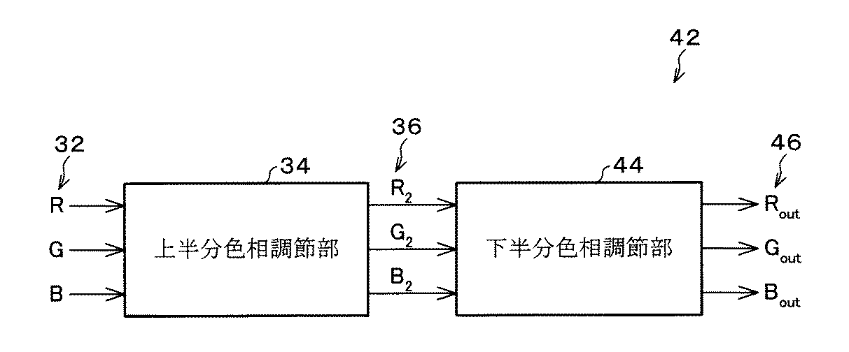
図7についての説明を続ける。等式(4)の左手に見えるベクトル(V1)は、ポイント「C」に対するCMY入力ポイントの位置付けを表す。等式(4)の右手に見える第1ベクトル(V2)は、ポイント「C」に対するポイント「P」の位置付けを表す。そして、等式(4)の右手に見える第2ベクトル(V3)は、ポイント「C」に対するポイント「S」の位置付けを表す。この等式の解は以下の式(5)のように求められる。
【0104】
【数2】
これらの各重み係数によって、最終のCMYK出力信号40が次の式(6)のように求められる。
【0106】
【数3】
ここで上付き添え字「(C)」、「(P)」、「(S)」をそれぞれ伴う各CMYK数値は各々、ポイント「C」、「P」、「S」における各CMYK中間信号にそれぞれ対応している。
【0108】
(上半分色相調節)
図5のブロック図に前処理ブロック58(ここでは第1処理ブロックと呼ばれる)を追加する。この前処理ブロック58は、各RGB信号を各CMY信号へと変換するだけであるが、この追加によって、各RGB入力信号を各CMYK出力信号へと変換するためのモデルが得られる。中心を通る対角線上の各CMYKルックアップテーブルは、カラーランプがニュートラルなグレーを再現し、かつL*出力応答がRGB入力信号に対し線形であるように設計される。
【0109】
また、6つの境界線分上の各CMYKルックアップテーブルは、適度に大きな色域を再現し、純色からブラックまでの境界線分上のランプにおける色相のずれを補正するよう設計される。立方体内部の各CMYポイントに対する各CMYK出力信号は、中心を通る対角線上及び境界線上の各CMYK出力信号から補間され、この補間によって、内部のポイントの適正な色相及び線形性といった所望の特性がうまく保持される。上記構成・方法は、本明細書において図3のブロック38との関連で「1ボックス構造」と説明されている。
【0110】
しかし、1ボックス構造は、RGB立方体の上半分の面における、各CMY入力ポイントに対応する各色相角度の出力には影響しない。なぜなら、これらの面における補間は、R,M,B,C,G,Yを結んでRに戻るRGB立方体中のホワイトポイントと、多面体上で隣接する2つの純色ポイントとにのみ基づいているからである。純色ポイントとホワイトポイントの間に、この領域内にて色相のずれを補正するための補間格子ポイントは存在しない。
【0111】
上記影響しないことを改善するために、前述の計算構造には、上半分の面における色相のずれを補正するための「2ボックス構造」と呼ばれる計算構造が用いられる。上半分の色相のずれを処理するための図3のブロック34は、各RGB入力信号を各CMY信号に変換するために、また、各RGB信号の色相のずれを補正するために構築される。一方、下半分の色相調節及びブラック生成部としての処理ブロック38は、中心を通る対角線上のグレーバランスを取るために、また、RGB入力立方体の下半分の面における色相のずれの問題を解決するために設計される。
【0112】
そのように、上半分の色相調節部としての処理ブロック34が設計・構築される時には、2次色領域におけるC2M2Y2信号は上記の所望の特性を既に所有している。つまりブロック34の目的は、RGB立方体の上半分の色相のずれの問題を補正する事にある。また、中心を通る対角線上のグレーバランスの問題は既に処理されているため、中心を通る対角線上のC2M2Y2信号は、ここでも等式(1)を使い、RGB信号を変換することによって得られる。
【0113】
しかし、境界線上では、各RGB信号を各CMY信号に変換するには、各1次元RGB-CMYルックアップテーブルが使用される。本発明の方法では、6セットの各1次元RGB-CMYルックアップテーブルが、R,G,B,C,M,Yの各々からホワイトポイントまでの境界線上にそれぞれ配置される。これらの1次元ルックアップテーブルへのインデックスは各RGB入力信号の最小値である。
【0114】
Wi=min(Ri,Gi,Bi) (7)
ブラックからホワイトへ中心を通って伸長する対角線上において、入力された各R,G,Bの各信号(ここではRGB入力信号と称する)は同等であり、等式(1)によるRGBからCMYへの変換が1次元線形関数によって、ブラックで100%からホワイトで0%までインプリメントされる(図8(a))。
【0115】
Rからホワイトまでの境界線上では、入力されたR信号が100%であり、入力されたG信号及びB信号(ここではGB入力信号と称する)は同等で、0%から100%まで推移する。図8(b)のプロットは、Rからホワイトまでの境界線上における、RGBからCMYへの各曲線の典型的なセットを表したものである。C曲線は0%で一定しているが、これは境界線上の色が最も純粋な色のままだからである。M曲線とY曲線は100%から0%まで変動するが、降下の勾配は等式(1)が示すようには直線的ではない。
【0116】
これらの各曲線は、Rからホワイトまでの境界線上で、色素の混合作用又は、ドットが重なり合わない(dot-off-dot)ハーフトーン効果によって生じうる色相のずれを補正するように形成されている。図5に示すように、2ボックス構造はブロック58とブロック38の組み合わせでもありうる。
【0117】
処理ブロックである、上半分色相調節部34の詳細は図9に示す。これは、処理ブロックである、下半分色相調節及びブラック生成部38と本質的に同一だが、各入力信号はRGBであり、ソータブロック62の出力は、順序付けされた各RGB信号とその順序情報である。ブロック34は重み生成器64と、CMYルックアップテーブル選択器66と、ルックアップテーブル66と、CMY補間器70とを含む。
【0118】
この処理ブロックで考察すべきK色素は存在しない。両ブロックの違いは、上半分のブロックにブラック(K)出力信号が存在せず、計算において立方体の各頂点(C,M,Y,K)及び(R,G,B,W)の役割が互いに逆転され、つまりRとCとが置換され、MとGとが置換される点にある。「CMYルックアップテーブル選択器及び1次元テーブルルックアップ」ブロックのための7セットの各1次元RGB-CMYルックアップテーブルの中で、境界線分上の6セットだけが柔軟に設計される。
【0119】
中心を通る対角線上のセットは、図8(a)のように固定される。実際には、C,M,Yからホワイトまでの境界線分上のルックアップテーブルは、知覚上の線形性を達成するよう設計されている。そして、RとGとBとからホワイトまでの各境界線分上の各ルックアップテーブルは、知覚上の線状性と、色素混合及び/又はドットが重なり合わないハーフトーン処理による色相のずれの補正とを、両方とも達成するように設計されている。
【0120】
処理ブロックである上半分色相調節部34に入力されたパラメータは、C,M,Y,R,G,Bの各々からホワイトまでの各線分上における、6セットの各CMYルックアップテーブルである。これらの各線分は図10に太線で表されている。これらの各線分上の各カラー出力は、同線分上の各CMYルックアップテーブルによって直接決定される。
【0121】
これらの各ルックアップテーブルは、各2次色からホワイトまでの各カラーランプの各色相角度をほぼ一定に保持し、その諧調に対し、知覚上の均一性のような所望の特性を幾つか与えるために設計されている。中には、これらの各ルックアップテーブルを1次色の各諧調について使用する場合もある。
【0122】
図7に見る補間処理についての幾何学的説明もまた、処理ブロックである上半分色相調節部34に対して有効である。しかし、各入力が各RGB信号であるため、RGB立方体については、各1次色がRとGとBとであり、各2次色がCとMとYとである。各重み係数を得るために、ここにも等式(5)が使用される。各CMY信号は次の数式で求められる。
【0123】
【数4】
下半分の色相調節に対応するCMY立方体の4面体区分と、上半分の色相調節に対応するRGB立方体の4面体区分とは互いに同一である。このため本発明の方法は、RGB立方体における補間のために、前記CMY立方体における補間に用いられるのと同じ計算を用いる。
【0125】
しかし、「下半分色相調節及びブラック生成部」のブロックによって、中心を通る対角線上のブラックからホワイトまでの各色のグレーバランスが既に取られているため、中心を通る対角線上にCMYルックアップテーブルを求める必要はない。その代わりに、中心を通る対角線上に補間を目的として各CMY数値を生成するには、各RGB入力信号の座標を単に変換するだけでよい。
【0126】
本明細書で開示される技術は、RGB、CMY又はCMYK以外の各出力色素にも適用される。例えば、4面体の境界線上に異なる各ルックアップテーブルを定めることで、ヘキサクローム(HexachromeTM)、CcMmYK、又は色素の他の設定法、もしくはXYZ,Labのような他の色空間を、信号から色へという単純な計算モデルとして扱う事ができる。
【0127】
(計算構造への発展)
これまでに述べた計算構造では、RGB又はCMY立方体において中心を通る対角線上に、また各1次色及び各2次色をブラック及びホワイトポイントと結びつける各境界線分上に、各1次元ルックアップテーブルが位置付けられる。各1次元ルックアップテーブルが配置された各線分上において、得られた各色出力の特性は、正確にコントロールする事ができる。
【0128】
しかし、信号入力立方体の他の部分における色出力についてはこれほど正確ではない。というのは、これらが近傍の各ルックアップテーブルによって補間されるからである。
【0129】
CMYKインクジェットプリンタを使った実験結果に基づき、各ルックアップテーブルが特定される各線分上の所望の特性を見出して、これを入力立方体の他の部分にうまく適用することもできる。
【0130】
しかし、時には、入力立方体の他の部分における色出力を正確にコントロールするのが望ましい場合がある。例えば、昔からあるプリンタのブルーポイントは、CとMとが100%でYが0%だが、いつも紫がかった色相を有する。Cを100%、Yを0%に保ちつつ、Mを減らすことで、より自然なブルーポイントを得ることができる。この自然なブルーポイントからブラック及びホワイトポイントまで、各カラーランプに沿った色相応答の出力を、正確にコントロールするのが望ましい場合もある。
【0131】
上記計算構造の一般的原理は、各1次色及び各2次色からホワイト及びブラックポイントまでの、中心を通る対角線上や、境界線分上にのみに各1次元ルックアップテーブルを配置することに限定されない。各ルックアップテーブルは、入力された、RGB又はCMY立方体内部の他の線分上にも位置付けられ、そこでの色出力の特性を正確にコントロールしうる。
【0132】
しかし、もしも計算構造に対し、より多くの各ルックアップテーブルが追加されれば、補間に使用されるべきルックアップテーブルのセットを選択するための、各入力信号からの順序情報だけが不十分になってしまう。追加の各ルックアップテーブルを利用するためには、追加の処理ステップが必要である。
【0133】
選択された4面体内部における、追加の線分上での各ルックアップテーブルの配置を、図11(a)に特に80にて示す。この例では2本の太線82、84上に、追加的な2セットの各ルックアップテーブルが配置される。Vs軸に垂直な平面は、追加的な線分とポイント「C」、「P」、「S」で交差し、ポイント「A」及び「B」でも交差する。入力(input)ポイントを含む三角形86は平面Vs=0に投射される(図11(b)参照)。
【0134】
各中間出力信号は、これら5つの交差点における、直接的なテーブルルックアップによって得られる。その図解は図11(b)にも示されているが、ここでポイント「C」、「P」、「S」で囲まれた三角形86は更に、4つの副次的な三角形(I〜IV)に分解される。上記△入力ポイントは、各ベクトルの適切なセット及び適切なセットの各ルックアップテーブルを選択するために定められる必要がある。
【0135】
上記入力ポイントは、行列(マトリクス)を転置することで代数的にテストされ、4つの三角形のうち何れが上記入力ポイントを含むのか確定される。最終の各出力信号は、入力ポイントを囲む副次的な三角形の3つの各頂点での中間信号から補間される。図11(b)の分割の図解は例示のためのものに過ぎず、最良の分割図解は特定の適用によって左右される。
【0136】
本発明の方法のもう1つの方式では、RGB/CMY信号立方体が6つ以上の各4面体に分割される。例えば、6つの上述された各4面体の1つ以上が、1次色と隣の2次色とを結ぶ4面体の境界線に追加的な頂点を導入することで分割される。中心を通る対角線や、上述された立方体表面の線分に加えて、他の線分を用いて立方体をもっと細かく分割することもできる。例えば、4面体の底辺に追加の頂点を導入してもよい(ここでVs=0である)。こうした場合でも、本明細書にて開示されている補間方法は本質的に同様に作用する。主な違いは、入力信号ベクトルを囲む4面体を識別するには、より複雑で高度なアルゴリズムが必要になるという点である。
【0137】
(実験結果)
計算構造の開発と発展から考えて、RGBからCMYK、又はRGBからRGBなどの、変換処理の様々な側面をコントロールするのに、この構造を利用しうる事は明らかである。本発明の方法を用いた実験では、RGBからCMYKへの変換モデルの色相調節及び出力色域の問題が重視され、研究の焦点になっていた。図3に見るように、本発明では2ステップの方法が構築され、「下半分色相調節及びブラック生成部」モジュールのために7セットの各CMYKルックアップテーブルが、「上半分色相調節部」モジュールのために6セットの各CMYルックアップテーブルが設計された。プリンタ色域はCIELAB空間で表される。色相調節のためには、CIELUV空間における色相角度が補正される。ただし、他の色空間を用いる事もできる。
【0138】
CMYKインクジェットプリンタの実験結果を、図12(a)と図12(b)の90、96、及び図13の110に示す。図12(a)では、レッドの色相リーフにおける、単純なUCR及びGCRインプリメンテーションの色域(線92)と、本発明の方法に基づく計算構造の色域(線94)とが比較されている。この実験結果から分かるのは、本発明の方法によって陰影領域に、より大きな色域を提供できることである。
【0139】
本発明で得られたレッドリーフにおける色域は更に、この色相角度にて、CMYKの色域全体と比較される(図12(b)、96)。CMYK全色域は線98であり、本発明の方法の計算構造により得られた色域のリーフは線100である。図12からは、本発明の方法で得られた色域のリーフがCMYK全色域に極めて近いことが分かる。
【0140】
この色相調節上の効果は図13(a)、(b)の110、116にそれぞれ示されている。どちらの図でも、補正された色相は実線で表される。図13(a)では、グリーンからブラックまでの補正済みの色相線112が、従来のインプリメンテーションから得られた色相線114と比較されている。また、図13(b)では、グリーンからホワイトまでの補正済みの色相線118と、未補正の色相線120とが比較されている。
【0141】
各RGB入力信号を各CMYKプリンタ出力信号に変換するための効率的な計算構造が開発された。この構造はCMYKプリンタをRGBプリンタとして製造するのに利用される。
【0142】
RGBプリンタの概略を述べるのは比較的簡単だが、それは、CIELAB空間やsRGB空間のような測色空間で特定される各色と、各RGB信号との間に、1対1の対応関係が成立するからである。
【0143】
本発明の計算構造は、1次元BG及びUCRの各ルックアップテーブルを用いた、従来のUCR及びGCR技術の単純なインプリメンテーションを発展させたものと考えられかもしれない。この構造では、RGB又はCMYの入力立方体の様々な部分に、複数セットの各1次元ルックアップテーブルが効果的に配置されて、製品化されたRGBプリンタの出力応答をコントロールしている。
【0144】
各1次元ルックアップテーブルの配置は、RGB又はCMYの入力立方体を幾つかの4面体へと本来的に分割し、4面体の各境界線上の各ルックアップテーブルが、4面体内部の入力ポイントに対応するCMYK出力信号の補間に利用される。
【0145】
本発明の計算構造は、RGBからCMYKへの変換のための2ステップの処理を構成するのに用いられて、充分に大きな色域を達成し、例えば各ハーフトーン又は各色素によって生じた色相のずれを補正する。実験結果からは、このモデルがCMYK全色域とほぼ同じ大きさの色域を達成可能であり、色相のずれをうまく補正できることが分かる。
【0146】
この計算構造の応用は、RGBからCMYKへの変換を行うプリンタだけに限定される訳ではない。それは4つ以上のインク又は色素を備えたプリンタの製造にも応用されうる。また、プリンタ以外の装置の望ましくない作動の補正にも利用されうる。
【0147】
このように、複数の各ルックアップテーブル及び補間を用いた、色相調節による色変換方法が開示された。添付された各請求項で定義される発明の範囲内ならば、この方法を更に変化させ、修正できることも明らかである。
【図面の簡単な説明】
【図1】下半分色相調節、及びブラック生成のためのCMY入力立方体を示すグラフである。
【図2】BG及び各UCRの各曲線、また両曲線と1次元CMYK応答出力曲線との関係をそれぞれ示す各グラフであって、(a)はBG及び各UCRの各曲線、(b)は中心を通る対角線上のCMYK応答曲線、(c)はCからブラックまでの境界線上におけるCMYK応答曲線、(d)はGからブラックまでの境界線上におけるCMYK応答曲線を示す。
【図3】RGBからCMYKへの変換の構造を示すブロック図である。
【図4】RGBからRGBへの変換の構造を示すブロック図である。
【図5】下半分の色相調節及びブラック生成に関する計算の構造を示すブロック図である。
【図6】(a)ないし(f)は6つの4面体に分割されたCMY入力立方体をそれぞれ示すグラフである。
【図7】テーブルルックアップ及び補間処理の幾何学的説明のためのグラフである。
【図8】(a)は固定されたブラックからホワイトまでの線における、1次元のRGBからCMYへの変換を示す曲線を示すグラフであり、(b)は本発明の方法に従って設計されたレッドからホワイトまでの線における、1次元のRGBからCMYへの変換を示す曲線を示すグラフである。
【図9】上半分色相調節に関する計算の構造を示すブロック図である。
【図10】上半分色相調節のためのRGB入力立方体を示すグラフである。
【図11】(a)は入力立方体の範囲内及びその表面上における追加的なルックアップテーブルと、(b)は適切なルックアップテーブルを選択するための方法とを表すグラフである。
【図12】本発明の方法で得られたレッドリーフの色域の図形的比較をそれぞれ示すグラフであって、(a)は従来のUCR及びGCRインプリメンテーションの色域との比較であり、(b)はCMYK色域全体との比較である。
【図13】(a)は従来のUCR及びGCRインプリメンテーションの結果生じた色相線、及びグリーンからブラックまでの線上における本発明の方法から生じた色相線、(b)はグリーンからホワイトまでの線上における補正済み及び未補正の色相との間の、CIELUV空間における色相角度の図形的比較をそれぞれ示すグラフである。(Related application)
This application is related to US patent application Ser. No. 09 / 741,458, filed Dec. 19, 2000, “Black Generation Method for CMYK Color Printers Using Multiple Lookup Tables and Interpolation”.
[0001]
(Invention)
The present invention belongs to the field of digital image color conversion, and in particular, RGB input signals are CMYK corresponding to printers having four dyes of cyan (C), magenta (M), yellow (Y), and black (K). A method for converting to a printer signal is a target, and a general color conversion method such as a color correction for an LCD display is a target.
[0002]
(Background of the Invention)
Many color printing apparatuses use four dyes, which are collectively referred to as CMYK dyes, cyan (C), magenta (M), yellow (Y), and black (K). A CMYK output device can generate many colors by combining one or more CMYK dyes. When the CMYK device is designed as an RGB device, it is necessary to form a combination unique to CMYK from each combination of RGB.
[0003]
Conventionally used to calculate these unique combinations are under color removal (UCR) and gray component replacement (GCR) techniques. Although these techniques can be easily implemented, the color gamut made available by the addition of K dye cannot be fully utilized.
[0004]
On the other hand, other powerful techniques that search the entire CMYK signal space for the desired combination yield good results, but are not suitable for real-time implementation.
[0005]
The use of K dye in addition to CMY dye has a number of effects. For example, dark black and subtle shadows can be obtained, and neutral color balance control can be simplified. An outline of a CMYK printer suitable for color management is as follows. That is, a combination of C, Y, M, and K dyes is calculated in order to reproduce a color specified in a colorimetric space such as CIELAB or sRGB. As described above, some colors are reproduced by a combination of a plurality of CMYK.
[0006]
In UCR and GCR techniques, RGB signals are first converted to obtain nominal CMY signals. Then, based on the CMY dye formulation, K dye is used instead of a certain amount of CMY dye. The amount of K dye used and the amount of CMY dye removed usually depends on the minimum input amount of C, M, Y. In a typical implementation, one black generation (BG) curve and three UCR curves are used. These curves are implemented as one-dimensional LUTs (look-up tables), where the minimum value of the CMY signal is used as an index into the look-up table. This provides a model for converting nominal RGB signals into printer CMYK signals.
[0007]
If such a model is provided, the printer is considered to be an RGB printer. In the RGB printer, for all colors in the color gamut, the RGB signal and the color specified in the colorimetric space correspond in a one-to-one relationship.
[0008]
The outline of the RGB printer is as follows. An RGB printer target with color patches is formed to sample the RGB input cube over a wide range and the CIELAB output value is measured. Then, based on the measurement data, a printer profile for converting the color specified in the colorimetric space into the printer RGB space is created. A gamut mapping technique is used to reproduce colors outside the gamut. Clearly, the RGB printer model is extremely useful in the modular design of the printer profiling process.
[0009]
Such a technique does not reveal the complexity of the RGB to CMYK conversion process and provides the user with a more intuitive RGB input color space. There are also applications such as Windows (registered trademark) Graphical Display Interface (GDI) printing. In such applications, the printer can only be addressed as an RGB device and requires the construction of an RGB printer model.
[0010]
The simple UCR / GCR technique described above does not provide enough flexibility to select the “best” CMYK combination to reproduce a particular color. A simple technique using a certain combination of CMYK values has a low capability, so that the color gamut of an RGB printer obtained by using it is also narrow.
[0011]
A more sophisticated way to control the use of CMYK is to search the entire color gamut of the CMYK printer to obtain the desired CMYK signal. Consider a single color specified in a colorimetric space. If the color is in the color gamut, the search will find one or more CMYK signal vectors that reproduce the input color. These CMYK signals are categorized by the amount of K dye used (from minimum to maximum).
[0012]
The desired CMYK signal can be obtained by specifying the relative amount of K dye used. One way to do this is to use parameters to specify the usage of K for the minimum and maximum amounts of K in the discovered CMYK signal vector. This parameter is set as a position function in the input color space for obtaining the optimum output image quality. In these methods, the CMYK printer color gamut is fully utilized.
[0013]
However, the entire printer CMYK space is sampled extensively, the target to be printed is measured in a colorimetric space such as CIELAB, and all CMYK signals corresponding to the colors in each color gamut specified in the colorimetric space are found. Building a printer target that performs interpolation is a “powerful” method with intensive calculations.
[0014]
Furthermore, the CMYK output signal is not related to the input color in the RGB signal space, but rather is related to the color in the colorimetric space. Therefore, these methods cannot be used for designing CMYK printers as RGB printers.
[0015]
Although these are useful for forming a three-dimensional color lookup table that directly converts each color in the colorimetric space into a CMYK printer signal, the gamut mapping technique must also be incorporated in the lookup table formation procedure. Needless to say.
[0016]
By using a black (K) dye for printing, a higher density than that obtained by combining only CMY dyes is realized. The problems that must be solved here are as follows. That is, how to determine the amount of black dye used based on RGB or CMY input values. Also, how should other dyes be adjusted once the black dye has been introduced? As mentioned above, the prior art shows two main solutions to this problem. These are (1) UCR type technology and (2) search technology. A related patent application describes a method for converting RGB input signals to CMYK signals using multiple black generation look-up tables and interpolations on the CMY cube boundary and diagonal through the center. ing.
[0017]
US Pat. No. 6,281,984 (Decker et al., August 28, 2001) “Externally defined four-dimensional dye (CMYK) and four inks (C′M′Y′K ′) attached to a given printer "Improved systems, methods and programs for converting to corresponding four-dimensional dyes defined for" describes the conversion of Lab numbers to CMYK numbers.
[0018]
US Pat. No. 6,229,580 (Inoue, granted on May 8, 2001) “Image color correction apparatus and recording medium having recorded color program” includes a color correction of a specific color tone and a plurality of colors related to the specific color tone. The color tone is described.
[0019]
US Pat. No. 6,191,874 (Yamada et al., Feb. 20, 2001) “Image Processing Apparatus and Method and Recording Medium” describes the extraction of colorless color components and the processing of CMY signals as a function of colorless color components. It explains about.
[0020]
US Pat. No. 6,140,997 (Tanaka, granted on Oct. 31, 2000) “Color characteristic extraction apparatus and method for converting RGB color space into color space close to human sense” Describes color processing performed by conversion to a degree / lightness (HLS) value.
[0021]
US Pat. No. 6,137,596 (Decker et al., Granted on Oct. 24, 2000) “System, method and program for converting 3D dyes to more than 3D dyes” and US Pat. No. 6,137,594 (Decker et al., 2000 10) May 24) "System, method and program for converting externally defined dyes (CMYK) to corresponding dyes (C'M'Y'K ') associated with a given printer", USA Patent No. 6,061,501 (Decker et al., Granted on May 9, 2000) “Regarding four externally defined dyes (CMYK) and four inks (C′M′Y′K ′) attached to a predetermined printer A system, method, and program for converting to a corresponding four-dimensional dye defined "combines a color space color patch with a black color space patch, and determines a color point value based on the measured Lab value. Convert as a function of black color space They are respectively described.
[0022]
US Pat. No. 6,057,931 (McConnell et al., May 2, 2000) “Color Image Copying Control Method and Apparatus” describes color correction of pixelated images by HSL values.
[0023]
US Pat. No. 6,039,434 (Moroney, granted May 21, 2000) “Thresholded Undercolor Removal and Black Replacement in Thermal Inkjet Printers or Plotters” describes the conversion of RGB signals to subtractive regions.
[0024]
US Pat. No. 5,987,168 (Decker et al., November 16, 1999) “System, Method, and Program for Converting a Three-Dimensional Dye to More Than a Three-Dimensional Dye” converts a three-color space into a four-color space For this reason, the formation of a lookup table is described.
[0025]
US Pat. No. 5,933,252 (Emori et al., August 3, 1999) “Color image processing method and apparatus therefor” converts a wide color space into a narrow color space while maintaining color continuity It explains about.
[0026]
US Pat. No. 5,894,358 (Ebner et al., Granted April 13, 1999) “Applicable Color Density Management System” describes UCR technology with all toner coverage addition and selective toner subtraction. .
[0027]
US Pat. No. 5,887,124 (Iwasaki et al., Granted March 23, 1999) “Image processing apparatus and method in which restriction processing is performed according to color component values” describes limiting the use of dyes.
[0028]
US Pat. No. 5,828,816 (Kise et al., Granted Oct. 27, 1998) “Image Processing Apparatus and Image Processing Method” describes a technique for improving blue reproduction.
[0029]
US Pat. No. 5,764,388 (Ueda et al., June 9, 1998) “Color Signal Conversion Method and Apparatus” describes the conversion of a color space signal into a signal having a colored space and a colorless space component. Yes.
[0030]
US Pat. No. 5,719,689 (Terada, granted Feb. 17, 1998) “Image Processing Device” describes the conversion of a color space signal into a color space and a black signal using a gray component extraction unit.
[0031]
US Pat. No. 5,717,839 (Ichikawa, granted on Feb. 10, 1998) “Image processor and printer having correction table data for external source transferred to printer” is dependent on image input device and image printer. An image correction look-up table for correcting the above is described.
[0032]
US Pat. No. 5,615,312 (Kohler, granted 25 Mar. 1997) “Color Management System with Business Graphics Representation Mode” describes BGR technology for improving color images.
[0033]
US Pat. No. 5,504,821 (Kanamori et al., Granted on April 2, 1996) “Color conversion device for performing three-dimensional color conversion on a color image in a color space using a small-capacity memory” is a lookup table. And performing color space conversion using color cubes.
[0034]
US Patent No. 5,146,328 (Yamasaki et al., Granted September 8, 1992) "Color Signal Network System" is a system that converts color signals to an output format that fits on a network with various input and output devices. Explains.
[0035]
US Pat. No. 5,113,248 (Hibi et al., Granted May 12, 1992) “Method and apparatus for color removal in image forming apparatus” describes a UCR system that performs color correction.
[0036]
U.S. Pat. No. 4,977,448 (Murata et al., Issued on Dec. 11, 1990) “Color Image Processing Device with Accurate Color Reproduction Performance” describes a system for correcting various color characteristics.
[0037]
US Pat. No. 4,965,664 (Udagawa et al., Issued October 23, 1990) “Color image signal processing method and apparatus for recording a color image from an input color image signal by converting individual color signal components” Describes the conversion of luminance, hue, and chromaticity (chromatic, saturation) signals into various output color space paradigms.
[0038]
U.S. Pat. No. 4,908,701 (Udagawa, granted on March 13, 1990) "Color image processing and apparatus for color adjustment during image processing" describes color correction as a function of the color component of dark points. .
[0039]
US Pat. No. 4,649,423 (Hoffrichter et al., Granted March 10, 1987) “Method and circuit adjustment for selective correction of hue and color” describes correction of color separation by processing HSL signals. .
[0040]
US Pat. No. 4,636,844 (Sasaki, granted Jan. 13, 1987) “Color Image Signal Processing Method” describes the processing of black signals as a function of color separation.
[0041]
US Pat. No. 4,553,835 (Morgan, Jr., granted 19 November 1985) “Procedure for Creating a Pre-Print Color Proof” explains the creation of a color separation proof as a function of the yellow content of an image. ing.
[0042]
US Pat. No. 4,500,919 (Schreiber, granted Feb. 19, 1985) “Color Reproduction System” describes the use of CRT tristimulus values to correct the final printed color values.
[0043]
(Summary of the Invention)
The color conversion method is
Preparing a first color region input signal set having a plurality of input signals;
Classify the input signals of the first color region input signal set according to the signal intensity,
Design and form multiple sets of one-dimensional lookup tables corresponding to color polyhedra,
Selecting a set of lookup tables for use with a particular color polyhedron, wherein the selection is a function of a section of the polyhedron determined as a function of the input signal set;
Look up the numbers in the lookup table set as a function of the input signal set,
Generate weights as a function of the classified signal strength,
Interpolating the output values from the selected look-up table as a function of the selected look-up table and the generated weights to generate a color gamut signal set that is converted to the desired color gamut signal set.
[0044]
An object of the present invention is to provide a model for converting a nominal RGB signal into a printer CMYK signal.
[0045]
Another object of the present invention is to provide a color conversion method that enables local conversion control from RGB signals to CMYK signals.
[0046]
Still another object of the present invention is to provide a color conversion method for controlling the use of CMYK dyes using a plurality of one-dimensional LUTs (look-up tables).
[0047]
Yet another object is to provide a color conversion method that uses a look-up table on the diagonal and boundary lines through the center of the input color cube.
[0048]
Yet another object is to provide a color conversion method that uses most of the available CMYK gamut.
[0049]
Yet another object is to provide a method for correcting discernable hue shifts.
[0050]
Yet another objective is neutral gray scale, accurate hue angle, and proper perception in color ramps (color gradients) from black to primary (primary) / black to secondary (mixed with primary). It is to provide a way to maintain space.
[0051]
Yet another object is to perform hue correction on the primary and secondary colors.
[0052]
The above summary and objectives of the present invention are for a quick grasp of the nature of the invention. For a more thorough understanding of the present invention, reference should be made to the following preferred embodiments of the invention in conjunction with the drawings.
[0053]
(Detailed description of preferred embodiments)
The method of the present invention includes a flexible computational structure for converting RGB (red, green, blue) or CMY (cyan, magenta, yellow) signals into CMYK (cyan, magenta, yellow, black) signals. Is included. Although this computational structure may be viewed as an evolution of conventional undercolor removal (UCR) and gray component replacement (GCR) techniques, multiple sets of one-dimensional CMYK look-up tables (LUTs) are used here. Thus, the use of CMYK dyes is controlled. The look-up table is arranged on the diagonal line passing through the center and on the boundary line in the input signal color cube to enhance the effect.
[0054]
Appropriately designing these look-up tables takes advantage of most of the available CMYK color gamut and still results in certain non-ideal device responses (eg downstream halftoning and page marking process results) A conversion model from RGB to CMYK is obtained that corrects any possible deviations in hue along a straight line from pure color to black or white. For example, the look-up table may be constrained so that the hue angle at each ramp from each pure color to white or black is constant.
[0055]
The present invention solves the problem of correction of sub-optimal color effects in “raw” (uncalibrated) output devices. When the method of the present invention is applied to color printing, the RGB input signals generally used in display monitors, digital cameras, and scanners are equivalent to those used in the majority of color printers (eg, inkjet or laser printers). Used to convert amounts of CMYK dyes. The method disclosed here is also applied to the correction of the powerful non-linear colorimetric effect of LCD displays. In the latter case, the present invention computes RGB to RGB conversion, rather than RGB to CMYK conversion. In this application, the computational structure will be slightly different. This is because only three channels need to be calculated, yet the principle is the same.
[0056]
The method of the present invention is an efficient computational structure for determining the conversion from nonlinear RGB to CMYK, RGB to RGB, or RGB to another color space, and is used to treat a CMYK printer as an RGB printer. The method of the present invention includes an efficient table lookup and interpolation technique that obtains an output signal based on the location of RGB points input into the RGB color cube. Here, a preferred specific example of the method of the present invention when this calculation structure is applied to a CMYK printer will be described. Expanded application to color printers that use more than four dyes (eg, Hexachrome TM printers, ie printers with CMYK plus bright cyan and bright magenta dyes) was very simple and understood the method of the invention It is considered possible enough for engineers in the field
With additional background explanation, a simple implementation of conventional UCR and GCR technologies will be reviewed. The method of the present invention develops this simple implementation to achieve an efficient computational structure that allows the flexibility to control the use of output dyes.
[0057]
(Conventional UCR and GCR implementation)
As shown in FIG. 1, the RGB input signal space is conceptually regarded as an RGB or CMY color cube 10. If the black point 12 (RGB signal is 0) is the origin and the three axes are RGB, this cube is an RGB cube. Alternatively, if the white point 14 (CMY signal is 0) is the origin, this cube is a CMY cube. That is, the RGB cube and the CMY cube show the same input signal space. Here, RGB and CMY signals are originally in the relationship of the following formula (1).
[0058]
C = 1.0-R, M = 1.0-G, Y = 1.0-B (1)
An outline of the black generation (BG) curve and the UCR curve is shown in FIG. There are three UCR curves here (C is indicated by a two-dot chain line, M is a broken line, and Y is indicated by a one-dot chain line). These curves are usually formed slightly different from each other. This is to obtain a visually neutral generated color that lies on a diagonal (
K i = Min (C i , M i , Y i (2)
An arbitrary CMY input signal and CMYK output signal are obtained by the following equation (3).
[0059]
C o = C i -UCR c (K i ),
M o = M i -UCR m (K i ),
Y o = Y i -UCR y (K i ),
K o = BG (K i (3)
Here, “UCR” and “BG” in FIG. 2A represent functions of UCR and BG. In equation (3), the subscript “o” represents output, and the subscript “i” represents input.
[0060]
According to equation (3) and FIG. 2 (a), 100% K is used at the black point, and the amount of CMY is greatly reduced. The reason for using 100% K at the black point is that the K dye can reproduce neutral and dark black. The amount of CMY in the black is reduced as necessary to fill the full coverage of the dye in the printing process. As the color becomes brighter, the amount of K dye decreases at a relatively high rate. On the other hand, the decrease amount of C, M, and Y is more gradual than that of K.
[0061]
On the diagonal line passing through the center of the input cube, the C, M, and Y signals are equivalent to each other and are called CMY input signals. The signal range is from 0% at the white point to 100% at the black point. Combining FIG. 2A and equation (3) on the diagonal 16 passing through the center, a one-dimensional CMYK output curve is obtained on the diagonal 16 passing through the center (FIG. 2B).
[0062]
In the pure cyan to black boundary color line segment 18 (C to black), the C input signal is fixed at 100%. The M and Y input signals are equivalent and are called MY input signals. These signals increase from 0% in C to 100% in black. By applying equation (3) and FIG. 2 (a), the relationship between the CMYK output signal and the MY input signal on the
[0063]
These are indicated by the bold lines in FIG. Another specific example is FIG. 2 (d), which illustrates the CMYK response output in the color line segment 26 from G to black. The C and Y signals input here are fixed at 100%, and the M signal varies from 0% in M to 100% in black. The curves in FIG. 2 are shown for illustration purposes only, and the relationship between FIG. 2 (a) and FIGS. 2 (b) through 2 (d) is only representative.
[0064]
Thus, the BG and UCR curves are used to guide a one-dimensional CMYK response output curve on a diagonal through the center and on each of the six boundaries. Here, each of the six boundary lines is a color line segment extending from a pure color to a black point in the CMY input cube, in short, a line segment.
[0065]
This also shows why the implementation of the BG and UCR curves is inflexible. 2B, if a diagonal CMYK response curve passing through the center as shown in FIG. 2B is specified, the BG and UCR curves in FIG. 2A and CMYK on a plurality of boundaries A response curve can also be derived.
[0066]
By properly designing a diagonal CMYK response curve through the center, the output color ramp on the diagonal is also controlled neutral. These curves represent the output ramp L perceived as linear for a diagonal CMY input signal through the center. * It is formed to respond (equal lightness).
[0067]
However, if the output response curve is formed to satisfy some constraints on the diagonal through the center, the response on the boundary is also fixed. Thus, the fact that different CMYK responses cannot be specified independently in different regions of the CMY input cube is that the conventional UCR and GCR approaches are inflexible and the color gamut of the CMYK printer is reduced. This is the main reason why it cannot be fully utilized.
[0068]
The following description is expressed in the form of CMYK printing of RGB images. If the CMYK response output curve on the diagonal line passing through the center and the CMYK response output curve on the six color line segments from each of C, M, Y, R, G, B to black are independently independent. If it can be specified, the use of CMYK can be controlled more flexibly. This is an important feature of the present invention.
[0069]
However, if the relationship of equation (3) is no longer valid, conventional UCR and GCR implementations based on BG and UCR curves will no longer function.
[0070]
The computational structure of the method of the present invention embodies an efficient interpolation algorithm for converting each RGB input signal to each CMYK signal, either independently or using locally specified CMYK response curves. ing. Other applications such as LCD color correction can be described in the same way.
[0071]
As discussed so far, and in the related applications described above, UCR-type techniques are not flexible enough to obtain optimal CMYK dye amounts for all RGB color inputs. Also, other methods that require an expanded search are computationally intensive. While these are useful for off-line creation of three-dimensional color look-up tables, they are not suitable for independent computational structures for converting RGB signals to CMYK signals.
[0072]
In the technique described in the aforementioned related application, interpolation and multiple black generation look-up tables are utilized to improve the flexibility of K usage over conventional UCR-type techniques. However, the use of CMY in the above related applications is still not very flexible.
[0073]
Referring again to FIG. 1, in addition to the black generation look-up table, the method of the present invention is pure from black to black on the diagonal of the CMY cube from the black through the center to the white and on the boundary of the cube. C, M, and Y look-up tables are also prepared on the trajectory leading to the primary and secondary colors. Thus, the present invention improves the flexibility of using CMY dyes.
[0074]
By properly designing each of these CMY look-up tables, neutral gray scale, accurate hue angles, and proper perceptual space in black to primary and black to secondary color ramps are maintained. The
[0075]
In the method of the present invention, a lookup table is also defined on the trajectory from the primary color and the secondary color to white. By appropriately designing these look-up tables, the hue angle and the perceptual space of the color ramp from white to primary and secondary colors are also controlled.
[0076]
The calculations required to realize the above advantages are not very complicated. This calculation is also applicable to embodiments in hardware or software. Each pure color trajectory is a closed (closed) polyhedron with their vertices being R, Y, C, B, M (according to the circulation order).
[0077]
In this specification, the terms “upper half” or “lower half” are used to roughly indicate each trajectory on the surface of the RGB / CMY color cube. "Upper half" Includes lines extending from C to white, M to white, Y to white, R to white, G to white, and B to white on the surface of the RGB / CMY cube Refers to the surface portion. That means In RGB / CMY cube The faces of three color cubes that intersect at the white point. The “upper half hue adjustment” is a total of six sets of one-dimensional RGB-CMY look-up tables arranged on each line segment included in the “upper half”, that is, R, G, B, C, RGB input signals corresponding to points on or inside the RGB / CMY cube using a total of six sets of one-dimensional RGB-CMY look-up tables respectively arranged on the boundary line from each of M and Y to the white point Is converted into a CMY signal. "Lower half" , Including line segments extending from C to black, from M to black, from Y to black, from R to black, from G to black, and from B to black on the surface of the RGB / CMY cube Refers to the surface portion. That means In RGB / CMY cube The faces of three color cubes that intersect at the black point. In addition, “lower half hue adjustment and black generation” is a total of seven sets of one-dimensional RGB-CMY look-up tables arranged on each of the line segments included in “lower half” and diagonal lines from white to black. In other words, a total of seven sets of one-dimensional RGB- arranged on line segments extending from C to black, from M to black, from Y to black, from R to black, from G to black, from B to black, and from white to black, respectively. It means a process of converting a nominal CMY signal corresponding to a surface or an internal point of an RGB / CMY cube into a printer CMYK signal using a CMY lookup table. Those of ordinary skill in the art will now understand that the method of the present invention is implemented with a particular problem in the upper or lower half of the cube. However, the color range of the entire cube is confirmed and changed by the balance of the upper half or the lower half.
[0078]
Next, “color area” and “color area signal set” will be described. A set of color gamuts and an associated set of color gamut signals can be briefly described using examples. One color area signal set is selected for input, which is referred to herein as the first color area or first color area signal set.
[0079]
The final color area, the final color area signal set, or the final dye signal set will be referred to as a third color area. This third color region is selected to provide a signal set for a particular output device such as a printer, copier, LCD or the like. An intermediate color region signal set of intermediate color regions or a set of secondary color regions is typically generated using the method of the present invention.
[0080]
The schematic structure of the RGB to CMYK conversion module according to the present invention is shown in FIG. In the first step, the path of each
[0081]
All colors are processed with the method of the invention in the sense that one color region is converted to another. Thus, the term “processing” here refers to the transformation of some or most of the colors that exist in the cube.
[0082]
The schematic structure of the RGB to RGB conversion module according to the present invention is shown in FIG. In the first step, the path of the
[0083]
Next, processing from RGB to CMYK will be described. In the method of the present invention used for printing, the
[0084]
Each line segment in which each one-dimensional lookup table of CMYK is defined is represented by a thick line in FIG. The positions at which these one-dimensional look-up tables are defined are the same as those in the aforementioned related application. However, in the related application, only one one-dimensional look-up table, that is, a K look-up table, was defined on these trajectories.
[0085]
On the other hand, in the present invention, each of the four one-dimensional lookup tables corresponding to CMYK is defined on these trajectories. By positioning each CMYK lookup table, not only the K dye but also the output of each CMY dye can be flexibly controlled.
[0086]
Each CMYK look-up table on the diagonal line and the boundary line segment passing through the center directly determines the output value of each CMYK on these line segments. Each CMYK output numerical value corresponding to each CMY input point that does not exist on these line segments is obtained by triangular interpolation based on the output values on these line segments (see also FIG. 7).
[0087]
Gray balance adjustment is made possible by limiting the one-dimensional lookup table on the diagonal through the center so that the dye output on the line segment from white to black produces a neutral grayscale ramp. The hue adjustment in the lower half limits the one-dimensional look-up table from black to pure color, and perceives CIELAB, CIELV, etc. in the dye output on the line segment from the primary color or the secondary color to black. This is possible by forming a color ramp with a constant measured hue angle in space. Further restrictions on the table design may force a uniform gradation on gray lamps or lamps from black to the primary and secondary colors.
[0088]
(Computation structure corresponding to conversion from RGB to CMYK)
The structure of the method of the present invention is to obtain a model for converting a nominal RGB signal into a CMYK dye signal that can be used in actual devices such as printers and copiers. As seen in FIG. 3, this structure has two parts. The upper half
[0089]
(Lower half hue adjustment and black generation)
Here, the lower half hue adjustment and
[0090]
Each thick line in FIG. 1 represents a location where these seven sets of CMYK look-up tables conceptually exist. Each of these lookup tables is specified independently of each other. The curves embodied in each of these lookup tables have the same general shape as the curves in FIGS. 2 (b) to 2 (d). FIG. 5 shows a calculation structure for converting each nominal CMY signal into each CMYK printer signal using each of these one-dimensional lookup tables.
[0091]
In tetrahedral interpolation techniques, it is well known that a unit signal cube can be divided into six tetrahedra based on the relative strength of the three signal components. These six tetrahedrons share a diagonal passing through the center of the cube as a common side. In the CMY cube of FIG. 1, each of the six tetrahedrons has CB-black-white, CG-black-white, MB-black-white, MR-black-white, Y- G-black-white, YR-black-white.
[0092]
Each of these vertices corresponds to each order of the following CMY input signal components, CMY, CYM, MCY, MYC, YCM, YMC. Here, the first component is the maximum and the final component is the minimum. In the first step of the conversion process, CMY input components are sorted by the
[0093]
Signal V in FIG. 5 represents order information. Each subscript l, m, and s indicates the maximum value, intermediate value, and minimum value of each CMY input signal component. That is, V l ≧ V m ≧ V s It becomes. This order information is transmitted to the look-up
[0094]
Once the tetrahedron is identified by the order signal V, the CMYK lookup table selector (block 50) selects three sets of each CMYK lookup table on the three sides of the tetrahedron.
[0095]
The
[0096]
The interpolation processing of the method of the present invention is basically the same as the interpolation processing of the related application described above. As shown in FIG. 6, the CMY input cube is divided into six tetrahedrons. For any CMY input point, the tetrahedron surrounding it is determined by the order information of the CMY signal. Each CMYK output signal corresponding to each CMY input point is interpolated by a CMYK look-up table from three sides connecting white, primary color, and adjacent secondary color to black on the tetrahedron surrounding it. . For example, if the CMY input point is C i ≧ M i ≧ Y i If the condition (where i = 2) is satisfied, the tetrahedron surrounding the point is one whose vertex is a black, white, cyan, or blue cube (FIG. 6A).
[0097]
The CMYK output signal is determined by interpolation from the CMYK look-up table on the diagonal line passing through the center from white to black, on the line segment connecting cyan and black, and on the line segment connecting blue and black. The order signal V is used to select a tetrahedron including CMY input points.
[0098]
Next, the smallest Vs of the CMY input signals is used as an index into the set of these CMYK lookup tables (LUTc, LUTp, LUTs), and three sets of CMYK intermediate signals (CMYK). (C) , CMYK (P) And CMYK (S) ) Respectively.
[0099]
That is, each CMYK look-up table on the three sides of this tetrahedron is used to obtain each CMYK output printer signal. Finally, the
[0100]
The interpolation process includes a
[0101]
Within the scope of this geometrical explanation, the method of the present invention is applicable to LUTc, LUTp, and LUTs within a triangle connecting three points “C” (center), “P” (primary), and “S” (secondary). The
[0102]
[Expression 1]
The description of FIG. 7 is continued. The vector (V 1 ) Represents the positioning of the CMY input point with respect to the point “C”. The first vector (V 2 ) Represents the positioning of the point “P” with respect to the point “C”. And the second vector (V Three ) Represents the positioning of the point “S” with respect to the point “C”. The solution of this equation is obtained as in the following equation (5).
[0104]
[Expression 2]
With these weighting factors, the final
[0106]
[Equation 3]
Here, each CMYK numerical value accompanied by the superscripts “(C)”, “(P)”, and “(S)” respectively represents the CMYK intermediate signals at the points “C”, “P”, and “S”. Each corresponds.
[0108]
(Upper half hue adjustment)
A preprocessing block 58 (referred to herein as a first processing block) is added to the block diagram of FIG. This
[0109]
Also, each CMYK lookup table on the six boundary segments is designed to reproduce a reasonably large color gamut and correct hue shifts in the lamps on the boundary segments from pure color to black. Each CMYK output signal for each CMY point inside the cube is interpolated from each diagonal and boundary CMYK output signal through the center, and this interpolation successfully achieves the desired characteristics such as proper hue and linearity of the internal points. Retained. The above configuration / method is described herein as “one box structure” in connection with
[0110]
However, the one-box structure does not affect the output of each hue angle corresponding to each CMY input point on the upper half surface of the RGB cube. This is because the interpolation in these planes is based only on the white point in the RGB cube connecting R, M, B, C, G, Y and returning to R, and two pure color points adjacent on the polyhedron. It is. There is no interpolated grid point for correcting the hue shift in this region between the pure color point and the white point.
[0111]
In order to improve the above-mentioned influence, a calculation structure called “2-box structure” for correcting a hue shift in the upper half surface is used for the above-described calculation structure. The
[0112]
As such, when the
[0113]
However, on the boundary line, to convert each RGB signal into each CMY signal, each one-dimensional RGB-CMY lookup table is used. In the method of the present invention, six sets of one-dimensional RGB-CMY lookup tables are respectively arranged on the boundary line from each of R, G, B, C, M, and Y to the white point. The index to these one-dimensional lookup tables is the minimum value of each RGB input signal.
[0114]
W i = Min (R i , G i , B i (7)
On the diagonal line extending from black to white through the center, the input R, G, B signals (herein referred to as RGB input signals) are equivalent, and from RGB to CMY according to equation (1). Is implemented by a one-dimensional linear function from 100% in black to 0% in white (FIG. 8 (a)).
[0115]
On the boundary line from R to white, the input R signal is 100%, and the input G signal and B signal (referred to as a GB input signal here) are equivalent and change from 0% to 100%. The plot of FIG. 8 (b) represents a typical set of each curve from RGB to CMY on the boundary from R to white. The C curve is constant at 0% because the color on the borderline remains the purest color. The M and Y curves vary from 100% to 0%, but the slope of the descent is not linear as equation (1) shows.
[0116]
Each of these curves is formed on the borderline from R to white to correct hue shifts that can be caused by dye mixing or dot-off-dot halftone effects. Yes. As shown in FIG. 5, the two-box structure may be a combination of
[0117]
Details of the upper half
[0118]
There are no K dyes to consider in this processing block. The difference between the two blocks is that there is no black (K) output signal in the upper half block, and the role of each vertex (C, M, Y, K) and (R, G, B, W) of the cube in the calculation. They are reversed from each other, that is, R and C are replaced, and M and G are replaced. Of the 7 sets of 1D RGB-CMY lookup tables for the “CMY Lookup Table Selector and 1D Table Lookup” block, only 6 sets on the boundary segment are flexibly designed.
[0119]
A set on a diagonal line passing through the center is fixed as shown in FIG. In practice, the lookup table on the boundary segment from C, M, Y to white is designed to achieve perceptual linearity. And each look-up table on each boundary line segment from R, G, B to white shows the perceptual linearity and hue shift due to dye mixing and / or halftone processing where dots do not overlap. Both are designed to achieve correction.
[0120]
The parameters input to the upper half
[0121]
Each of these look-up tables keeps each hue angle of each color ramp from each secondary color to white substantially constant and gives the tone some desired characteristics such as perceptual uniformity. Designed for. In some cases, each of these lookup tables is used for each tone of the primary color.
[0122]
The geometrical explanation of the interpolation processing shown in FIG. 7 is also effective for the upper half
[0123]
[Expression 4]
The tetrahedron section of the CMY cube corresponding to the hue adjustment of the lower half and the tetrahedron section of the RGB cube corresponding to the hue adjustment of the upper half are the same. For this reason, the method of the present invention uses the same calculations as used for interpolation in the CMY cube for interpolation in the RGB cube.
[0125]
However, since the gray balance of each color from black to white on the diagonal line passing through the center has already been taken by the “lower half hue adjustment and black generation unit” block, the CMY lookup table is set on the diagonal line passing through the center. There is no need to ask. Instead, in order to generate each CMY numerical value for the purpose of interpolation on a diagonal line passing through the center, the coordinates of each RGB input signal need only be converted.
[0126]
The technique disclosed in this specification is also applied to each output dye other than RGB, CMY, or CMYK. For example, by defining different lookup tables on the tetrahedron boundary line, hexachrome (Hexachrome) TM ), CcMmYK, or other setting methods of dyes, or other color spaces such as XYZ, Lab can be treated as a simple calculation model from signal to color.
[0127]
(Development to calculation structure)
In the calculation structure described so far, each one-dimensional lookup is on a diagonal line through the center in the RGB or CMY cube and on each boundary line segment connecting each primary color and each secondary color with the black and white points. The table is positioned. On each line segment on which each one-dimensional lookup table is arranged, the characteristics of each obtained color output can be accurately controlled.
[0128]
However, color output in other parts of the signal input cube is not so accurate. This is because they are interpolated by each nearby lookup table.
[0129]
Based on experimental results using a CMYK ink jet printer, each look-up table can find the desired characteristic on each line segment identified and apply it successfully to other parts of the input cube.
[0130]
However, sometimes it may be desirable to accurately control the color output in other parts of the input cube. For example, the blue point of an old printer has 100% C and M and 0% Y, but always has a purple hue. A more natural blue point can be obtained by reducing M while keeping C at 100% and Y at 0%. From this natural blue point to the black and white points, it may be desirable to accurately control the output of the hue response along each color ramp.
[0131]
The general principle of the above calculation structure is that each one-dimensional lookup table is arranged only on the diagonal line through the center and the boundary line segment from each primary color and each secondary color to the white and black points. It is not limited to. Each look-up table can also be located on other line segments within the input RGB or CMY cube, where the color output characteristics can be precisely controlled.
[0132]
However, if more each lookup table is added to the computational structure, only the order information from each input signal is insufficient to select the set of lookup tables to be used for interpolation. turn into. In order to utilize each additional lookup table, additional processing steps are required.
[0133]
The arrangement of each look-up table on the additional line segment within the selected tetrahedron is shown in FIG. In this example, two additional sets of lookup tables are arranged on the two
[0134]
Each intermediate output signal is obtained by a direct table lookup at these five intersections. The illustration is also shown in FIG. 11 (b), where the triangle 86 surrounded by the points “C”, “P”, “S” is further divided into four secondary triangles (I to IV). ). The Δ input point needs to be defined to select the appropriate set of each vector and each lookup table of the appropriate set.
[0135]
The input points are tested algebraically by transposing a matrix to determine which of the four triangles contains the input points. Each final output signal is interpolated from the intermediate signals at each of the three vertices of the secondary triangle surrounding the input point. The partition diagram of FIG. 11 (b) is for illustration only, and the best partition diagram depends on the particular application.
[0136]
In another scheme of the method of the present invention, the RGB / CMY signal cube is divided into six or more tetrahedrons. For example, one or more of each of the six tetrahedrons described above may be split by introducing additional vertices at the tetrahedron border connecting the primary color and the adjacent secondary color. In addition to the diagonal line passing through the center and the above-described line segments on the cube surface, other line segments can be used to further divide the cube. For example, an additional vertex may be introduced at the base of the tetrahedron (where Vs = 0). Even in such cases, the interpolation method disclosed herein works essentially the same. The main difference is that a more complex and sophisticated algorithm is required to identify the tetrahedron surrounding the input signal vector.
[0137]
(Experimental result)
It is clear that this structure can be used to control various aspects of the conversion process, such as RGB to CMYK or RGB to RGB, in view of the development and evolution of the computational structure. In the experiment using the method of the present invention, the problem of the hue adjustment and the output color gamut of the conversion model from RGB to CMYK was emphasized, and was the focus of research. As shown in FIG. 3, in the present invention, a two-step method is constructed, and for each of the “lower half hue adjustment and black generator” modules, seven sets of CMYK lookup tables are added to the “upper half hue adjuster” module. Six sets of each CMY look-up table were designed for. The printer color gamut is represented in CIELAB space. In order to adjust the hue, the hue angle in the CIELV space is corrected. However, other color spaces can be used.
[0138]
The experimental results of the CMYK ink jet printer are shown at 90 and 96 in FIGS. 12A and 12B and 110 in FIG. In FIG. 12 (a), a simple UCR and GCR implementation color gamut (line 92) in the red hue leaf is compared with the color gamut of the computational structure based on the method of the present invention (line 94). Yes. This experimental result shows that the method of the present invention can provide a larger color gamut in the shadow area.
[0139]
The color gamut in the red leaf obtained in the present invention is further compared with the entire color gamut of CMYK at this hue angle (FIGS. 12B and 96). The CMYK full color gamut is
[0140]
This effect on hue adjustment is shown at 110 and 116 in FIGS. 13 (a) and 13 (b), respectively. In both figures, the corrected hue is represented by a solid line. In FIG. 13A, the corrected
[0141]
An efficient calculation structure for converting each RGB input signal into each CMYK printer output signal has been developed. This structure is used to manufacture a CMYK printer as an RGB printer.
[0142]
Although it is relatively easy to outline an RGB printer, there is a one-to-one correspondence between each color specified in a colorimetric space such as CIELAB space or sRGB space and each RGB signal. Because.
[0143]
The computational structure of the present invention may be thought of as an evolution of a simple implementation of conventional UCR and GCR techniques using one-dimensional BG and UCR look-up tables. In this structure, multiple sets of one-dimensional look-up tables are effectively placed in various parts of the RGB or CMY input cube to control the output response of the commercialized RGB printer.
[0144]
The layout of each one-dimensional lookup table inherently divides the RGB or CMY input cube into several tetrahedrons, and each lookup table on each tetrahedron boundary is the input point inside the tetrahedron. Used for interpolation of corresponding CMYK output signals.
[0145]
The computational structure of the present invention is used to construct a two-step process for the conversion from RGB to CMYK to achieve a sufficiently large color gamut, e.g. of the hues produced by each halftone or each dye. Correct the deviation. From the experimental results, it can be seen that this model can achieve a color gamut that is almost the same size as the entire CMYK color gamut and can correct the hue shift well.
[0146]
The application of this calculation structure is not limited to printers that perform conversion from RGB to CMYK. It can also be applied to the manufacture of printers with more than four inks or pigments. It can also be used to correct undesired operation of devices other than printers.
[0147]
Thus, a color conversion method by hue adjustment using a plurality of lookup tables and interpolation has been disclosed. It will also be apparent that the method may be further varied and modified within the scope of the invention as defined in the appended claims.
[Brief description of the drawings]
FIG. 1 is a graph showing a CMY input cube for lower half hue adjustment and black generation.
FIG. 2 is a graph showing each curve of BG and each UCR, and a relationship between both curves and a one-dimensional CMYK response output curve, wherein (a) is a curve for BG and each UCR, and (b) is a graph. The CMYK response curve on the diagonal line passing through the center, (c) shows the CMYK response curve on the boundary line from C to black, and (d) shows the CMYK response curve on the boundary line from G to black.
FIG. 3 is a block diagram showing the structure of conversion from RGB to CMYK.
FIG. 4 is a block diagram showing the structure of conversion from RGB to RGB.
FIG. 5 is a block diagram showing a calculation structure related to hue adjustment and black generation in the lower half.
FIGS. 6A to 6F are graphs showing CMY input cubes divided into six tetrahedrons, respectively.
FIG. 7 is a graph for geometrical explanation of table lookup and interpolation processing.
FIG. 8A is a graph showing a curve showing a one-dimensional RGB to CMY conversion in a fixed black to white line, and FIG. 8B is a red designed according to the method of the present invention. It is a graph which shows the curve which shows the conversion from 1-dimensional RGB to CMY in the line from to white.
FIG. 9 is a block diagram illustrating a calculation structure related to upper half hue adjustment;
FIG. 10 is a graph showing an RGB input cube for upper half hue adjustment;
FIG. 11A is a graph representing an additional lookup table within and on the surface of the input cube, and FIG. 11B is a method representing a method for selecting an appropriate lookup table.
FIG. 12 is a graph showing a graphical comparison of the color gamut of red leaves obtained by the method of the present invention, respectively, where (a) is a comparison with the color gamut of a conventional UCR and GCR implementation; (B) is a comparison with the entire CMYK color gamut.
13A is a hue line resulting from conventional UCR and GCR implementations, and a hue line resulting from the method of the present invention on a line from green to black, and FIG. 13B is a line from green to white. FIG. 6 is a graph showing a graphical comparison of hue angles in CIE LUV space between corrected and uncorrected hues on a line, respectively.
Claims (5)
RGB色領域の信号をCMY色領域の信号に変換する第1色変換工程と、
上記第1色変換工程によって変換されたCMY色領域の信号をCMYK色領域の信号に変換する第2色変換工程とを含み、
上記第2色変換工程は、
ホワイトを示す点、ブラックを示す点、RGBの各純色を示す点、およびCMYの各純色を示す点を頂点とする色立方体における、ホワイトを示す点からブラックを示す点まで伸長する線分上、および上記各純色を示す点からブラックを示す点まで伸長する線分上に存在する複数の点と、当該各点を上記CMYK色領域の色成分で表現した各色成分の値との対応関係を上記線分毎かつ上記色成分毎に示した1次元ルックアップテーブルの中から、上記CMY色領域の信号に応じて色成分毎に3つの1次元ルックアップテーブルを選択する選択工程と、
選択した上記各1次元ルックアップテーブルを用いて上記CMY色領域の信号を上記CMYK色領域の信号に変換する変換工程とを含み、
ホワイトを示す点からブラックを示す点まで伸長する線分に対応する上記1次元ルックアップテーブルは、ニュートラルなグレーを再現し、かつ等明度出力応答がRGB入力信号に対し線形であるように設計され、上記各純色を示す点からブラックを示す点まで伸長する線分に対応する上記1次元ルックアップテーブルは、色相のずれを補正するように設計されており、
上記選択工程では、
上記色立方体を、ホワイトを示す点からブラックを示す点まで伸長する線分を辺として含む6つの4面体に分割し、これら6つの4面体の中から上記CMY色領域の信号に対応する点を含む4面体を抽出し、この抽出した4面体を構成する4つの頂点のうち、ブラックを示す点から他の3点まで伸長する3つの線分に対応する1次元ルックアップテーブルをCMYK色領域の色成分毎に選択し、
上記変換工程では、
上記CMY色領域の信号に対応する点の座標を(Vl,Vm,Vs)とし、この座標(Vl,Vm,Vs)の点を含み、かつ上記他の3点を含む平面に平行な平面と、上記3つの線分との各交点C,P,Sの座標をそれぞれ(Vs,Vs,Vs)、(1,Vs,Vs)、(1,1,Vs)としたときに、重み付け係数w1およびw2をw1=(Vl−Vm)/(1−Vs)およびw2=(Vm−Vs)/(1−Vs)に基づいて算出し、上記選択工程で選択した1次元ルックアップテーブルによって上記各交点C,P,Sに対応するCMYK色領域の各色成分の信号を特定し、CMYK色領域の各色成分について、交点Cに対応するCMYK色領域の信号に(1−w1−w2)を乗じた値と、交点Pに対応するCMYK色領域の信号にw1を乗じた値と、交点Sに対応するCMYK色領域の信号にw2を乗じた値とを加算した値を色変換後の上記CMYK色領域の信号として算出することを特徴とする色変換方法。A color conversion method for converting an RGB color region signal into a CMYK color region signal,
A first color conversion step of converting RGB color region signals into CMY color region signals;
A second color conversion step of converting the CMY color region signal converted by the first color conversion step into a CMYK color region signal,
The second color conversion step is
On a line segment extending from a point indicating white to a point indicating black in a color cube having a point indicating white, a point indicating black, a point indicating each pure color of RGB, and a point indicating each pure color of CMY, And a correspondence relationship between a plurality of points existing on a line segment extending from a point indicating each pure color to a point indicating black and a value of each color component in which each point is expressed by a color component of the CMYK color region. A selection step of selecting three one-dimensional lookup tables for each color component in accordance with a signal of the CMY color region from one-dimensional lookup tables shown for each line segment and for each color component;
Converting each of the CMY color area signals into the CMYK color area signals using each of the selected one-dimensional lookup tables,
The one-dimensional lookup table corresponding to the line segment extending from the point indicating white to the point indicating black is designed to reproduce neutral gray and the linearity response to the RGB input signal. The one-dimensional lookup table corresponding to the line segment extending from the point indicating each pure color to the point indicating black is designed to correct a hue shift,
In the above selection process,
The color cube is divided into six tetrahedrons including a line segment extending from a point indicating white to a point indicating black as sides, and a point corresponding to the signal of the CMY color region is selected from these six tetrahedrons. A tetrahedron including the extracted four-hedron and a one-dimensional lookup table corresponding to three line segments extending from the point indicating black to the other three points among the four vertices constituting the extracted tetrahedron is displayed in the CMYK color region. Select for each color component,
In the conversion process,
The coordinates of the points corresponding to the signals in the CMY color area are (Vl, Vm, Vs), a plane including the coordinates (Vl, Vm, Vs) and parallel to the plane including the other three points; When the coordinates of the intersections C, P, S with the three line segments are (Vs, Vs, Vs), (1, Vs, Vs) , (1, 1, Vs), respectively, the weighting coefficient w1 And w2 are calculated based on w1 = (Vl−Vm) / (1−Vs) and w2 = (Vm−Vs) / (1−Vs), and each of the above values is calculated by the one-dimensional lookup table selected in the selection step. A signal of each color component of the CMYK color region corresponding to the intersections C, P, S is specified, and for each color component of the CMYK color region, the signal of the CMYK color region corresponding to the intersection C is multiplied by (1-w1-w2). And w1 in the CMYK color region signal corresponding to the intersection point P A color conversion method characterized in that a value obtained by adding the multiplied value and a value obtained by multiplying a signal of the CMYK color region corresponding to the intersection S by w2 is calculated as a signal of the CMYK color region after color conversion.
ホワイトを示す点、ブラックを示す点、RGBの各純色を示す点、およびCMYの各純色を示す点を頂点とする色立方体における、上記各純色を示す点からホワイトを示す点まで伸長する線分上に存在する複数の点と、当該各点を上記CMY色領域の色成分で表現した各色成分の値との対応関係を上記線分毎かつ上記色成分毎に示した1次元ルックアップテーブルの中から、上記RGB色領域の信号に応じて色成分毎に2つの1次元ルックアップテーブルを選択する選択工程と、
選択した上記各1次元ルックアップテーブルを用いて上記RGB色領域の信号を上記CMY色領域の信号に変換する変換工程とを含み、
CMYの各純色を示す点からホワイトを示す点まで伸長する線分に対応する上記1次元ルックアップテーブルは、知覚上の線形性を達成するように設計され、RGBの各純色を示す点からホワイトを示す点まで伸長する線分に対応する上記1次元ルックアップテーブルは、知覚上の線形性と色素混合及び/又はドットが重なり合わないハーフトーン処理による色相のずれの補正とを達成するように設計されており、
上記選択工程では、
上記色立方体を、ホワイトを示す点からブラックを示す点まで伸長する線分を辺として含む6つの4面体に分割し、これら6つの4面体の中から上記RGB色領域の信号に対応する点を含む4面体を抽出し、この抽出した4面体を構成する4つの頂点のうち、ホワイトを示す点から他の3点のうちブラックを示す点を除く2点まで伸長する2つの線分に対応する1次元ルックアップテーブルをCMY色領域の色成分毎に選択し、
上記変換工程では、
上記RGB色領域の信号に対応する点の座標を(Vl,Vm,Vs)とし、この座標(Vl,Vm,Vs)の点を含み、かつ上記他の3点を含む平面に平行な平面と、ホワイトを示す点からブラックを示す点まで伸長する線分との交点Cの座標を(Vs,Vs,Vs)、上記平面と上記2つの線分との各交点P,Sの座標をそれぞれ(1,Vs,Vs)、(1,1,Vs)としたときに、重み付け係数w1およびw2をw1=(Vl−Vm)/(1−Vs)およびw2=(Vm−Vs)/(1−Vs)に基づいて算出し、上記交点Cに対応する上記RGB色領域の信号の座標をC=1.0−R、M=1.0−G、およびY=1.0−Bに基づいて変換することによって上記交点Cに対応する上記CMY色領域の各色成分の信号を特定し、上記選択工程で選択した1次元ルックアップテーブルによって上記各交点P,Sに対応するCMY色領域の各色成分の信号を特定し、CMY色領域の各色成分について、交点Cに対応するCMY色領域の信号に(1−w1−w2)を乗じた値と、交点Pに対応するCMY色領域の信号にw1を乗じた値と、交点Sに対応するCMYK色領域の信号にw2を乗じた値とを加算した値を色変換後の上記CMY色領域の信号として算出することを特徴とする請求項1または2に記載の色変換方法。The first color conversion step includes
A line segment extending from a point indicating each pure color to a point indicating white in a color cube whose vertex is a point indicating white, a point indicating black, a point indicating each pure color of RGB, and a point indicating each pure color of CMY A one-dimensional lookup table showing a correspondence relationship between a plurality of existing points and the values of the color components obtained by expressing the points with the color components of the CMY color region for each line segment and each color component. A selection step of selecting two one-dimensional lookup tables for each color component from among the RGB color region signals;
Converting the RGB color region signals into the CMY color region signals using each of the selected one-dimensional lookup tables,
The one-dimensional lookup table corresponding to a line segment extending from a point indicating each CMY pure color to a point indicating white is designed to achieve perceptual linearity. The one-dimensional look-up table corresponding to the line segment extending to a point indicating, so as to achieve perceptual linearity and correction of hue deviation by dye mixing and / or halftone processing where dots do not overlap Designed,
In the above selection process,
The color cube is divided into six tetrahedrons including a line segment extending from a point indicating white to a point indicating black as a side, and a point corresponding to the signal of the RGB color region is selected from these six tetrahedrons. Corresponding to two line segments extending from the four vertices constituting the extracted tetrahedron to two points excluding the point indicating black from the other three points excluding the point indicating black among the other four points. Select a one-dimensional lookup table for each color component in the CMY color area,
In the conversion process,
The coordinates of the points corresponding to the signals in the RGB color area are (Vl, Vm, Vs), a plane including the coordinates (Vl, Vm, Vs) and parallel to the plane including the other three points; , the coordinates of intersection C between the line segment extending to a point which indicates a black terms indicating white (Vs, Vs, Vs), the intersection P between the plane and the two line segments, the coordinates of S, respectively ( 1, Vs, Vs) and (1, 1, Vs), the weighting coefficients w1 and w2 are set to w1 = (Vl−Vm) / (1−Vs) and w2 = (Vm−Vs) / (1− Vs) and the coordinates of the RGB color region signal corresponding to the intersection C are based on C = 1.0-R, M = 1.0-G, and Y = 1.0-B. By converting, a signal of each color component in the CMY color region corresponding to the intersection C is specified, and A signal of each color component of the CMY color region corresponding to each of the intersection points P and S is specified by the one-dimensional lookup table selected in the selection step, and a signal of the CMY color region corresponding to the intersection point C for each color component of the CMY color region. Is multiplied by (1-w1-w2), a value obtained by multiplying the signal in the CMY color region corresponding to the intersection P by w1, and a value obtained by multiplying the signal in the CMYK color region corresponding to the intersection S by w2. 3. The color conversion method according to claim 1, wherein the added value is calculated as a signal of the CMY color area after color conversion.
C=1.0−R、M=1.0−G、およびY=1.0−Bを演算することによってRGB色領域の信号をCMY色領域の信号に変換することを特徴とする請求項1または2に記載の色変換方法。In the first color conversion step,
An RGB color region signal is converted into a CMY color region signal by calculating C = 1.0-R, M = 1.0-G, and Y = 1.0-B. 3. The color conversion method according to 1 or 2.
Applications Claiming Priority (1)
| Application Number | Priority Date | Filing Date | Title |
|---|---|---|---|
| US10/156,279 US7190487B2 (en) | 2001-09-25 | 2002-05-27 | Color conversion with hue straightening using multiple look-up tables and interpolation |
Publications (2)
| Publication Number | Publication Date |
|---|---|
| JP2004007509A JP2004007509A (en) | 2004-01-08 |
| JP4159912B2 true JP4159912B2 (en) | 2008-10-01 |
Family
ID=30442346
Family Applications (1)
| Application Number | Title | Priority Date | Filing Date |
|---|---|---|---|
| JP2003083933A Expired - Fee Related JP4159912B2 (en) | 2002-05-27 | 2003-03-25 | Color conversion method with hue correction using multiple lookup tables and interpolation |
Country Status (1)
| Country | Link |
|---|---|
| JP (1) | JP4159912B2 (en) |
Families Citing this family (3)
| Publication number | Priority date | Publication date | Assignee | Title |
|---|---|---|---|---|
| US7605959B2 (en) * | 2005-01-05 | 2009-10-20 | The Ackley Martinez Company | System and method of color image transformation |
| JP4921254B2 (en) * | 2007-06-20 | 2012-04-25 | 株式会社リコー | Image processing apparatus, image processing method, control program, and recording medium |
| JP4687753B2 (en) | 2008-06-30 | 2011-05-25 | ブラザー工業株式会社 | Color conversion table creation program, color conversion table creation device, and color conversion table creation method |
-
2003
- 2003-03-25 JP JP2003083933A patent/JP4159912B2/en not_active Expired - Fee Related
Also Published As
| Publication number | Publication date |
|---|---|
| JP2004007509A (en) | 2004-01-08 |
Similar Documents
| Publication | Publication Date | Title |
|---|---|---|
| US7190487B2 (en) | Color conversion with hue straightening using multiple look-up tables and interpolation | |
| US7944594B2 (en) | Image processing device and an image processing method for curbing the amount of color material consumed and suppressing a deterioration in image quality | |
| US5572632A (en) | Universal frame buffer for a rendering device | |
| US7016530B2 (en) | Image processing method, image processing apparatus, and programs thereof | |
| US5657137A (en) | Color digital halftoning using black and secondary color replacement | |
| US7019868B2 (en) | Black generation method for CMYK color printer using multiple lookup tables and interpolation | |
| US5875260A (en) | Image processing apparatus and method for altering color image signals | |
| US8335015B2 (en) | Systems and methods for building a color lookup table for a printer | |
| EP0665674A2 (en) | Colour printer system | |
| AU7834698A (en) | Gamut correction with color separation and methods and apparatuses for performing same | |
| US20080007806A1 (en) | Image processing method, image processing apparatus, computer program product, and recording medium for image processing | |
| JP2008219791A (en) | Image processor, image processing method, program, and recording medium | |
| JPH11341296A (en) | Color area conversion method and color area converter | |
| JP4081944B2 (en) | Color separation image correction method, chart, ink jet printer, color separation image correction device, and recording medium | |
| US7986448B2 (en) | Image processing apparatus and image processing method for the same | |
| JP5777497B2 (en) | Color processing apparatus and method | |
| JP4518408B2 (en) | Image processing apparatus, method, and program | |
| US7679783B2 (en) | System and method for extracting grayscale data within a prescribed tolerance | |
| US8005299B2 (en) | Adjusting colorants specified in a digital image | |
| JP5324405B2 (en) | Color processing apparatus and method, and image forming apparatus | |
| JP2005176280A (en) | Color image processing method, color image processing apparatus, color image processing program, and storage medium | |
| JP4159912B2 (en) | Color conversion method with hue correction using multiple lookup tables and interpolation | |
| JP4139590B2 (en) | CMYK color printer black generation method using multiple look-up tables and interpolation method | |
| JP2012129912A (en) | Printer | |
| JP5777322B2 (en) | Color processing apparatus and color processing method |
Legal Events
| Date | Code | Title | Description |
|---|---|---|---|
| A621 | Written request for application examination |
Free format text: JAPANESE INTERMEDIATE CODE: A621 Effective date: 20050810 |
|
| A977 | Report on retrieval |
Free format text: JAPANESE INTERMEDIATE CODE: A971007 Effective date: 20070830 |
|
| A131 | Notification of reasons for refusal |
Free format text: JAPANESE INTERMEDIATE CODE: A131 Effective date: 20070904 |
|
| A521 | Request for written amendment filed |
Free format text: JAPANESE INTERMEDIATE CODE: A523 Effective date: 20071102 |
|
| RD02 | Notification of acceptance of power of attorney |
Free format text: JAPANESE INTERMEDIATE CODE: A7422 Effective date: 20071102 |
|
| A131 | Notification of reasons for refusal |
Free format text: JAPANESE INTERMEDIATE CODE: A131 Effective date: 20080325 |
|
| A521 | Request for written amendment filed |
Free format text: JAPANESE INTERMEDIATE CODE: A523 Effective date: 20080523 |
|
| TRDD | Decision of grant or rejection written | ||
| A01 | Written decision to grant a patent or to grant a registration (utility model) |
Free format text: JAPANESE INTERMEDIATE CODE: A01 Effective date: 20080715 |
|
| A01 | Written decision to grant a patent or to grant a registration (utility model) |
Free format text: JAPANESE INTERMEDIATE CODE: A01 |
|
| A61 | First payment of annual fees (during grant procedure) |
Free format text: JAPANESE INTERMEDIATE CODE: A61 Effective date: 20080716 |
|
| R150 | Certificate of patent or registration of utility model |
Ref document number: 4159912 Country of ref document: JP Free format text: JAPANESE INTERMEDIATE CODE: R150 Free format text: JAPANESE INTERMEDIATE CODE: R150 |
|
| FPAY | Renewal fee payment (event date is renewal date of database) |
Free format text: PAYMENT UNTIL: 20110725 Year of fee payment: 3 |
|
| FPAY | Renewal fee payment (event date is renewal date of database) |
Free format text: PAYMENT UNTIL: 20110725 Year of fee payment: 3 |
|
| FPAY | Renewal fee payment (event date is renewal date of database) |
Free format text: PAYMENT UNTIL: 20120725 Year of fee payment: 4 |
|
| FPAY | Renewal fee payment (event date is renewal date of database) |
Free format text: PAYMENT UNTIL: 20120725 Year of fee payment: 4 |
|
| FPAY | Renewal fee payment (event date is renewal date of database) |
Free format text: PAYMENT UNTIL: 20130725 Year of fee payment: 5 |
|
| LAPS | Cancellation because of no payment of annual fees |