JP4158250B2 - Information recording / reproducing apparatus and method, and providing medium - Google Patents
Information recording / reproducing apparatus and method, and providing medium Download PDFInfo
- Publication number
- JP4158250B2 JP4158250B2 JP34551898A JP34551898A JP4158250B2 JP 4158250 B2 JP4158250 B2 JP 4158250B2 JP 34551898 A JP34551898 A JP 34551898A JP 34551898 A JP34551898 A JP 34551898A JP 4158250 B2 JP4158250 B2 JP 4158250B2
- Authority
- JP
- Japan
- Prior art keywords
- information recording
- signal
- video
- generating
- circuit
- Prior art date
- Legal status (The legal status is an assumption and is not a legal conclusion. Google has not performed a legal analysis and makes no representation as to the accuracy of the status listed.)
- Expired - Fee Related
Links
Images


Description
【0001】
【発明の属する技術分野】
本発明は、情報記録再生装置および方法、並びに記録媒体に関し、特に、例えば、テレビジョン放送の映像信号を、所定の時間間隔でサムネイル画像として記録するようにした情報記録再生装置および方法、並びに記録媒体に関する。
【0002】
【従来の技術】
従来、テレビジョン放送を録画するVCR(Video Cassette Recorder)には、録画した番組の放映日時、チャンネル、および番組のジャンル等のインデックス情報を、ビデオカセットテープの冒頭に記録する機能を有するものが存在する。
【0003】
そのようなVCRによれば、番組が録画されているビデオカセットテープの冒頭を再生させるだけで、録画されている番組のインデックス情報を得ることが可能であるが、ビデオカセットテープの全てを再生しなければ、録画されている番組の具体的な内容を知ることはできない。
【0004】
そこで、ビデオカセットテープの全てを再生することなく、録画されている番組の具体的な内容をユーザに把握させる方法として、例えば、録画時において、録画している番組の映像信号から所定の間隔で静止画像(または、サムネイル画像)を抽出して、ビデオテープの所定の位置にまとめて記録し、ビデオカセットテープに録画されている番組の内容を確認するときに、その所定の位置だけを再生する方法が考えられる。
【0005】
【発明が解決しようとする課題】
しかしながら、上述したような、所定の間隔で静止画像を抽出する方法では、番組(本編)の途中に放送されるコマーシャル等のような、番組(本編)の内容とは無関係である部分の静止画像も抽出して記録してしまうので、CMの静止画像が番組内容を把握するときの妨げとなる課題があった。
【0006】
本発明はこのような状況に鑑みてなされたものであり、テレビジョン放送に含まれるコマーシャルを検出することにより、本編の静止画像だけを記録できるようにするものである。
【0007】
本発明の情報記録再生装置は、映像信号を取得する取得手段と、映像信号に対応する映像のうちのコマーシャル映像を検出する検出手段と、コマーシャル映像が検出されていない期間において周期的なタイミング信号を発生する発生手段と、発生されたタイミング信号に同期して映像信号の縮小静止画像を生成する生成手段と、生成された縮小静止画像を情報記録媒体に記録する記録手段とを備える。
【0008】
本発明の情報記録再生方法は、映像信号を取得する取得ステップと、映像信号に対応する映像のうちのコマーシャル映像を検出する検出ステップと、コマーシャル映像が検出されていない期間において周期的なタイミング信号を発生する発生ステップと、発生されたタイミング信号に同期して映像信号の縮小静止画像を生成する生成ステップと、生成された縮小静止画像を情報記録媒体に記録する記録ステップとを含む。
【0009】
本発明の記録媒体は、映像信号を取得する取得ステップと、映像信号に対応する映像のうちのコマーシャル映像を検出する検出ステップと、コマーシャル映像が検出されていない期間において周期的なタイミング信号を発生する発生ステップと、発生されたタイミング信号に同期して映像信号の縮小静止画像を生成する生成ステップと、生成された縮小静止画像を情報記録媒体に記録する記録ステップとを含む処理を情報記録再生装置のコンピュータに実行させるプログラムが記録されている。
【0010】
本発明においては、取得された映像信号に対応する映像のうちのコマーシャル映像が検出され、コマーシャル映像が検出されていない期間において周期的なタイミング信号が発生され、発生されたタイミング信号に同期して映像信号の縮小静止画像が生成されて情報記録媒体に記録される。
【0011】
【発明の実施の形態】
以下に本発明の実施の形態を説明するが、特許請求の範囲に記載の発明の各手段と以下の実施の形態との対応関係を明らかにするために、各手段の後の括弧内に、対応する実施の形態(但し一例)を付加して本発明の特徴を記述すると、次のようになる。但し勿論この記載は、各手段を記載したものに限定することを意味するものではない。
【0012】
本発明の情報記録再生装置は、前記映像信号を取得する取得手段(例えば、図1のチューナ2)と、前記映像信号に対応する映像のうちのコマーシャル映像を検出する検出手段(例えば、図2のCM検出回路21)と、前記コマーシャル映像が検出されていない期間において周期的なタイミング信号を発生する発生手段(例えば、図2のタイミング信号発生回路22)と、発生された前記タイミング信号に同期して前記映像信号の縮小静止画像を生成する生成手段(例えば、図2の画像縮小回路25)と、生成された前記縮小静止画像を情報記録媒体に記録する記録手段(例えば、図1の書き込み回路6)とを備える。
【0013】
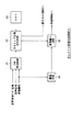
本発明を適用したDVR(Digital Video Recorder)の構成例について、図1を参照して説明する。記録系のチューナ2は、端子1から入力されるテレビジョン放送のRF信号を復調し、得られた映像信号、音声信号、および音声多重モードを示す信号(以下、音声多重モード信号と記述する)を、サムネイル画像作成回路4に出力する。また、チューナ2は、映像信号および音声信号を変調回路3に出力する。
【0014】
変調回路3は、チューナ2から入力された映像信号および音声信号を、所定の方式(例えば、MPEG2方式)で圧縮符号化し、さらに、所定の変調方式(例えば、EFM変調方式)で変調して書き込み回路7に出力する。書き込み回路7は、変調された番組の映像信号および音声信号を記録媒体9に記録する。
【0015】
サムネイル画像作成回路4は、チューナ2から入力された各信号を用いて、番組(本編)の途中で放送されるコマーシャル(以下、CMと記述する)を検出する。また、サムネイル画像作成回路4は、検出したCM以外の本編において、所定のタイミングで映像信号から静止画像を抽出し、得られた静止画のサムネイル画像(縮小画像)を生成して変調回路5に出力する。さらに、サムネイル画像作成回路4は、CMが検出されたタイミングの情報を書き込み回路6に出力する。
【0016】
変調回路5は、サムネイル画像作成回路4から入力されたサムネイル画像のデータを、変調回路3と同様に、所定の方式(例えば、JPG方式)で圧縮符号化し、さらに、所定の変調方式(例えば、EFM変調方式)で変調して書き込み回路6に出力する。書き込み回路6は、変調されたサムネイル画像のデータを記録媒体8に記録する。また、書き込み回路6は、サムネイル画像作成回路4から入力された、CMが検出されたタイミングの情報に基づいて、記録媒体8に記録されてしまったCMのサムネイル画像のデータを削除する。記録媒体8,9は、例えば、CD-R、光磁気ディスク、ハードディスク、半導体メモリ等、ランダムアクセス可能な媒体である。
【0017】
再生系の読み取り回路10は、ユーザから入力されるコマンドに対応して、記録媒体8に記録されているサムネイル画像のデータを読み取って復調し、図示せぬモニタに供給する。読み取り回路11は、ユーザから入力されるコマンドに対応して、記録媒体9に記録されている番組の映像信号および音声信号を読み取って復調し、図示せぬモニタに供給する。
【0018】
なお、書き込み回路6,7、記録媒体8,9、および、読み取り回路10,11を、それぞれ一体化して、番組の映像信号および音声信号、並びにCMのサムネイル画像を一体化された記録媒体に記録するようにしてもよい。
【0019】
次に、その動作について説明する。このDVRにおいては、ユーザからの録画コマンドに対応して、チューナ2で受信されたテレビジョン放送の番組の信号(映像信号および音声信号)が、変調回路3で変調され、書き込み回路7により記録媒体9に記録される。上述した番組録画処理と平行して、サムネイル画像作成回路4で、チューナ2で受信されたテレビジョン放送のCMではない本編のサムネイル画像が作成され、作成されたサムネイル画像が変調回路5で変調され、書き込み回路6により記録媒体8に記録される。
【0020】
また、このDVRにおいては、ユーザからの再生コマンドに対応して、読み取り回路11により記録媒体9に記録されている番組の映像信号および音声信号が再生される。さらに、ユーザからのサムネイル画像再生コマンドに対応して、読み取り回路10により記録媒体9に対応する記録媒体8に記録されたサムネイル画像が再生される。再生されたサムネイル画像は、記録媒体9に録画されている番組の内容を把握する場合や検索を行いたい場合に利用される。
【0021】
図2は、図1のサムネイル画像作成回路4の構成例を示している。チューナ2から入力された映像信号、音声信号、および音声多重モード信号は、サムネイル画像作成回路4において、CM検出回路21に入力される。映像信号は、遅延回路24にも入力される。CM検出回路21は、チューナ2から入力された各信号がCMであるか否かをフレーム毎に判定し、その判定結果をタイミング信号発生回路22に出力する。なお、CM検出回路21の構成については後述する。
【0022】
タイミング信号発生回路22は、CM検出回路21から入力されたCMの検出結果と、タイマ23から入力される所定の周期信号(例えば、1分ごとに発信される信号)とを用いてタイミング信号を発生し、画像縮小回路25に供給する。また、タイミング信号発生回路22は、CM検出回路21から入力されたCMの検出結果を書き込み回路6に出力する。
【0023】
遅延回路24は、チューナ2から入力された映像信号を、CM検出回路21およびタイミング信号発生回路22の処理に要する時間だけ遅延して画像縮小回路25に出力する。
【0024】
画像縮小回路25は、タイミング信号発生回路22から供給されたタイミング信号に同期して、遅延回路24から入力された映像信号のサムネイル画像を生成し、変調回路5に出力する。
【0025】
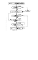
次に、このDVRのサムネイル記録系の動作について、図3のフローチャートを参照して説明する。このサムネイル画像記録処理は、ユーザからの録画コマンドに対応して開始される、チューナ2、変調回路3、および書き込み回路7からなる番組録画系の処理と平行して実行され、番組録画系の処理が終了するとき、終了される。
【0026】
ステップS1において、サムネイル画像作成回路4のCM検出回路21は、チューナ2から入力された映像信号、音声信号、および音声多重モード信号を用いてフレーム単位でCMを検出し、その検出結果をタイミング信号発生回路22に出力する。なお、このCM検出処理の詳細は後述する。
【0027】
ステップS2において、タイミング信号発生回路22は、CM検出回路21から入力されたCMの検出結果と、タイマ23から入力される1分毎の周期信号とを用いてタイミング信号を発生し、画像縮小回路25に供給する。また、タイミング信号発生回路22は、CM検出回路21から入力されたCMの検出結果を示す情報を書き込み回路6に出力する。このタイミング信号発生処理の詳細について、図4のフローチャートを参照して説明する。
【0028】
タイミング信号発生回路22は、ステップS11において、番組録画系の処理が終了したか否かを判定し、番組録画系の処理が終了していないと判定した場合、ステップS12に進む。ステップS12において、タイミング信号発生回路22は、タイマ23をリセットする。
【0029】
ステップS13において、タイミング信号発生回路22は、タイマ23の計測時間が1分を経過したか否かを判定し、計測時間が1分を経過していないと判定した場合、ステップS14に進む。
【0030】
ステップS14において、タイミング信号発生回路22は、CM検出回路21からCMの開始点を示す情報が入力されたか否かを判定する。CMの開始点を示す情報が入力されていないと判定された場合、ステップS13に戻る。その後、ステップS13において、計測時間が1分を経過したと判定された場合、ステップS16に進む。
【0031】
ステップS16において、タイミング信号発生回路22は、タイミング信号を画像縮小回路25に出力する。
【0032】
ステップS14において、CMの開始点を示す情報が入力されたと判定された場合、ステップS15に進む。ステップS15において、タイミング信号発生回路22は、CM検出回路21からCMの終了点を示す情報が入力されたか否かを判定し、CMの終了点を示す情報が入力されたと判定するまで待機する。
【0033】
ステップS15において、CMの終了点を示す情報が入力されたと判定された場合、ステップS16に進む。
【0034】
なお、ステップS11において、番組録画系の処理が終了したと判定されるまで、このタイミング信号発生処理は繰り返される。
【0035】
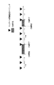
図5は、上述したタイミング信号発生処理による、タイミング信号の発生時期を表している。すなわち、テレビジョン放送の本編においては、所定の間隔(本実施例においては、1分間隔)でタイミング信号が発生され、CM開始点からCM終了点までの区間においてはタイミング信号は発生されず、CM終了点の直後から、再度、所定の間隔(1分間隔)でタイミング信号が発生される。
【0036】
図3の説明に戻る。ステップS3において、画像縮小回路25は、タイミング信号発生回路22から入力されたタイミング信号に同期して、遅延回路24を介して入力されたテレビジョン放送の映像信号からサムネイル画像を生成する。このサムネイル画像生成処理の詳細について、図6のフローチャートを参照して説明する。
【0037】
ステップS21において、画像縮小回路25は、タイミング信号発生回路22から入力されたタイミング信号に同期して、遅延回路24を介して入力されたテレビジョン放送の映像信号から静止画像(フレーム画像)を抽出する。
【0038】
ステップS22において、画像縮小回路25は、ステップS21で抽出した静止画像の空間周波数の高周波成分を除去するために、ローパスフィルタ処理を施す。ステップS23において、画像縮小回路25は、高周波成分が除去された静止画像を構成する画素を、所定の間隔で間引いて静止画像を所定のサイズを縮小し、得られたサムネイル画像を変調回路5に出力する。
【0039】
図3のステップS4にリターンする。ステップS4において、変調回路5は、サムネイル画像作成回路4から入力されたサムネイル画像のデータを所定の方法で変調して書き込み回路6に出力する。書き込み回路6は、変調されたサムネイル画像のデータを記録媒体8に記録する。
【0040】
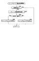
ここで、このDVRのサムネイル記録系の動作をリアルタイムでモニタした画面を図7に示す。図7(A)に示すように、サムネイル画像記録処理のステップS1乃至S4(図3)においては、CMではない本編のサムネイル画像を周期的に記録媒体8に記録するようにしているが、図7(B)に示すように、各部の処理の遅延によりCMのサムネイル画像が記録媒体8に記録されてしまうことがある。
【0041】
そこで、ステップS5において、書き込み回路6は、図7(C)に示すように、タイミング信号発生回路22から入力された、CM検出回路21のCMの検出結果を示す情報を用いて、記録媒体8に誤って記録されたCMのサムネイル画像を削除する。CM終了直後のサムネイル画像は、図7(D)に示すように、削除されたCM区間のサムネイルが表示されていた位置に表示される。
【0042】
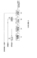
ここで、図2のCM検出回路21について説明する。図8は、CM検出回路21の構成例を示している。このCM検出回路21において、チューナ2から入力される音声多重モード信号はCM区間検出部36に供給され、映像信号は遅延部34およびシーンチェンジ検出部35に供給され、音声信号はA/D変換部32に供給される。
【0043】
無音閾値決定部31は、A/D変換部32でデジタル化された音声信号を用いて無音区間検出処理に用いられる閾値を演算し、無音区間検出部33に供給する。
【0044】
無音区間検出部33は、A/D変換部32から入力されるデジタル化された音声信号のレベルと、無音閾値決定部31から供給された閾値を比較することにより、無音区間を検出し、その結果をシーンチェンジ検出部35に出力する。
【0045】
シーンチェンジ検出部35は、同時に入力される2枚のフレーム画像(現フレームと、遅延部34により1フレーム時間(1/30秒)だけ遅延された前フレーム)を比較して、無音区間におけるシーンチェンジの有無を検出し、その結果をCM区間検出部36に出力する。
【0046】
CM区間検出部36は、音声多重モード信号と、シーンチェンジ検出部35から供給されたシーンチェンジの情報をフレーム毎に2値化して、内蔵するメモリに記憶し、その情報に基づいてCM区間を検出し、CM区間の開始点および終了点をタイミング信号発生回路22に出力する。なお、CM区間検出部36が内蔵するメモリには、過去1分間の情報を記憶させる。その場合、内蔵されるメモリの容量は、
60(秒)×30(フレーム)×2(データ)×1(ビット)
となる。
【0047】
次に、CM検出回路21の動作について、図9のフローチャートを参照して説明する。このCM検出処理は、チューナ2からCM検出回路21に各信号が入力されたときに開始される。ステップS31において、CM検出回路21の無音閾値決定部31は、無音区間検出処理(ステップS32)に用いられる閾値を無音区間検出部33に出力する。
【0048】
ここで、無音閾値決定処理の詳細について、図10のフローチャートを参照して説明する。ステップS41において、A/D変換部32は、チューナ2から入力された所定の微少時間の音声信号(アナログ)を、所定のサンプリング周波数、所定の量子化レベルでデジタル化し、得られたデジタル音声信号(例えば、図11(A))を無音閾値決定部31に出力する。無音閾値決定部31は、ステップS42において、A/D変換部32から入力されたデジタル音声信号を、図11(B)に示すように絶対値化し、ステップS43において、絶対値化されたサンプルのレベルの平均値(図11(C))を演算する。
【0049】
ステップS44において、無音閾値決定部31は、ステップS43で得た平均値と、それまで記憶していた閾値とを比較して、小さい方の値を新たな閾値として記憶する。
【0050】
ステップS45において、無音閾値決定部31は、全てのチャンネルに対してステップS41乃至S44の処理を実行したか否かを判定し、全てのチャンネルに対して処理を実行していないと判定した場合、ステップS46に進む。ステップS46において、無音閾値決定部31は、チューナ2にチャンネル切換信号を出力する。このチャンネル切換信号に対応して、チャンネルが切り替えられる。
【0051】
その後、ステップS45において、全てのチャンネルに対して、ステップS41乃至S44の処理を実行したと判定された場合、無音閾値決定処理を終了する。なお、この無音閾値決定処理は、常に所定の間隔(例えば、10分毎)で繰り返して実行される。
【0052】
なお、無音閾値決定処理の方法は、上述した方法以外にも考えられる。例えば、映像信号は存在するが、音声信号のレベルは確実に0となる、各チャンネルの放送開始時刻、および放送終了時刻において、音声信号を受信し、そのレベルnに所定のオフセット値Δを加えた値n+Δを無音閾値としてもよい。ただし、各チャンネルの放送開始時刻および放送終了時刻は既知であるものとする。
【0053】
図9に戻る。ステップS32において、無音区間検出部33は、ステップS31で無音閾値決定部31から入力された閾値に基づいて無音区間を検出する。この無音区間検出処理の詳細について、図12のフローチャートを参照して説明する。
【0054】
ステップS51において、A/D変換部32は、チューナ2から入力された、所定の微少時間の音声信号(アナログ)を所定のサンプリング周波数、および所定の量子化レベルでデジタル化し、得られたデジタル音声信号(例えば、図11(A))を無音閾値決定部31に出力する。無音区間検出部33は、ステップS52において、A/D変換部32から入力されたデジタル音声信号を、図11(B)に示すように絶対値化し、ステップS53において、絶対値化されたサンプルのレベルの平均値(図11(C))を演算する。
【0055】
ステップS54において、無音閾値決定部31は、ステップS53で得た平均値が、無音閾値決定部31から入力された閾値よりも小さいか否かを判定し、平均値が閾値よりも小さいと判定した場合、ステップS55に進む。ステップS55において、無音区間検出部33は、この区間を無音区間と判定し、その情報をシーンチェンジ検出部35に出力する。
【0056】
反対に、ステップS54において、平均値が閾値よりも小さくないと判定された場合、ステップS56に進む。ステップS56において、無音区間検出部33は、この区間を無音区間ではない(有音区間である)と判定し、その情報をシーンチェンジ検出部35に出力する。
【0057】
図9のステップS33にリターンする。ステップS33において、シーンチェンジ検出部35は、入力された前後する2枚のフレームにおけるシーンチェンジを検出し、その結果をCM区間検出部36に出力する。このシーンチェンジ検出処理の詳細について、図13のフローチャートを参照して説明する。
【0058】
ステップS61において、シーンチェンジ検出部35は、無音区間検出部33から入力された情報が無音区間を示すものであるか否かを判定し、入力された情報が無音区間を示す情報であると判定した場合、ステップS62に進む。
【0059】
ステップS62において、シーンチェンジ検出部35は、入力された前後する2枚のフレーム画像の相関値Eを演算する。具体的には、図14に示すように、遅延部34を介して入力された画像(遅延画像)と、遅延部34を介さずに入力された画像(スルー画像)の対応する画素の画素値の差の絶対値の総和が相関値Eとして次式により演算される。
E=Σ|Dij−Sij|
ただし、Dij,Sijは、それぞれ、遅延画像またはスルー画像の座標(i,j)の画素値を表している。なお、この相関値Eは、フレーム間の相関の程度が小さいくなると、その値は大きくなり、フレーム間の相関の程度が大きくなると、その値は小さくなる。
【0060】
ステップS63において、シーンチェンジ検出部35は、ステップS62で得られた相関値Eが所定の閾値よりも大きいか否かを判定し、相関値Eが所定の閾値よりも大きい(フレーム間の相関の程度が小さい)と判定した場合、ステップS64に進む。
【0061】
ステップS64において、シーンチェンジ検出部35は、入力された前後する2枚のフレーム間にはシーンチェンジが存在すると判定して、その情報をCM区間検出部36に出力する。
【0062】
反対に、ステップS63において、相関値Eが所定の閾値よりも大きくない(フレーム間の相関の程度が大きい)と判定された場合、ステップS65に進む。
【0063】
ステップS65において、シーンチェンジ検出部35は、入力された前後する2枚のフレーム間にはシーンチェンジがないと判定して、その情報をCM区間検出部36に出力する。
【0064】
なお、ステップS61において、無音区間を示す情報ではないと判定された場合、その情報がCM区間検出部36に出力される。
【0065】
図9のステップS34にリターンする。ステップS34において、CM区間検出部36は、内蔵するメモリに2値化して記憶している過去1分間のフレーム単位の音声多重モード信号およびシ−ンチェンジ検出部35からの情報に基づいてCM区間を判定する。
【0066】
すなわち、CM区間検出部36に内蔵されるメモリには、図15に示すように、音声多重モード信号(Audio_Multi[])については、ステレオモードが1、モノラルモードおよび2カ国語モードが0として記録され、シーンチェンジ検出部35から入力された情報(Scene_Change[]))については、シーンチェンジであるフレームには1、シーンチェンジではないフレームには0が記録されている。
【0067】
CM区間検出部36は、内蔵するメモリを参照し、図16(A)に示すように、シーンチェンジを示す信号が1であるフレーム(シーンチェンジ点)毎に区間(いまの場合、シーンチェンジ区間0乃至10)を区切り、各シーンチェンジ区間を構成するフレーム数を30で除算することにより、その区間の時間を演算する。また、CM区間検出部36は、図16(B)に示すように、音声多重モード信号が1であって連続しているフレームをステレオ区間とする。さらに、CM区間検出部36は、図16(C)に示すように、単独のシーンチェンジ区間の時間、または隣接する複数のシーンチェンジ区間の合計時間が15秒の整数倍であり、且つ、ステレオ区間である区間をCM区間と判定し、CM区間の開始点および終了点を示す信号をタイミング信号発生回路22に出力する。
【0068】
以上のように、本発明を適用したDVRのサムネイル画像記録処理においては、テレビジョン放送の本編だけを周期的に、特に、本編の内容を強く反映していることが多いCM終了直後のサムネイル画像を記録するようにしたので、記録媒体8に記録されたサムネイル画像は、本編の内容を把握する場合や検索する場合に役立つものとなる。
【0069】
なお、上記各処理を行うコンピュータプログラムは、磁気ディスク、CD-ROM等の情報記録媒体よりなる提供媒体のほか、インターネット、デジタル衛星などのネットワーク提供媒体を介してユーザに提供することができる。
【0070】
【発明の効果】
以上のように、本発明によれば、本編の静止画像だけを記録することが可能となる。
【図面の簡単な説明】
【図1】本発明を適用したDVRの構成例を示すブロック図である。
【図2】図1のサムネイル画像作成回路4の構成例を示すブロック図である。
【図3】 DVRのサムネイル画像記録処理を説明するフローチャートである。
【図4】図2のタイミング信号発生回路22の動作を説明するフローチャートである。
【図5】タイミング信号の発生時期を説明するための図である。
【図6】図3のステップS3のサムネイル画像生成処理を説明するフローチャートである。
【図7】 DVRのサムネイル画像記録処理を説明するための図である。
【図8】図2のCM検出回路21の構成例を示すブロック図である。
【図9】CM検出回路21の動作を説明するフローチャートである。
【図10】図8の無音閾値決定部31の動作を説明するフローチャートである。
【図11】図8の無音閾値決定部31の動作を説明するための図である。
【図12】図9のステップS32の無音区間検出処理を説明するフローチャートである。
【図13】図9のステップS33のシーンチェンジ検出処理を説明するフローチャートである。
【図14】シーンチェンジ検出処理を説明するための図である。
【図15】CM区間検出部36に内蔵されるメモリに記録されている情報を説明するための図である。
【図16】CM区間検出部36の処理を説明するための図である。
【符号の説明】
2 チューナ, 3 変調回路, 4 サムネイル画像作成回路, 5 変調回路, 6,7 書き込み回路, 8,9 記録媒体, 10,11 読み取り回路, 21 CM検出回路, 22 タイミング信号発生回路, 23 タイマ, 24 遅延回路, 25 画像縮小回路[0001]
BACKGROUND OF THE INVENTION
The present invention relates to an information recording / reproducing apparatus and method, andRecordRegarding media, especiallyFor example,Information recording / reproducing apparatus and method for recording television broadcast video signals as thumbnail images at predetermined time intervals, andRecordIt relates to the medium.
[0002]
[Prior art]
Conventionally, some VCRs (Video Cassette Recorders) that record television broadcasts have the function of recording index information such as the broadcast date and time, channel, and program genre of the recorded program at the beginning of the video cassette tape. To do.
[0003]
According to such a VCR, it is possible to obtain the index information of the recorded program simply by playing the beginning of the video cassette tape on which the program is recorded. Without it, the specific contents of the recorded program cannot be known.
[0004]
Therefore, as a method for allowing the user to grasp the specific contents of the recorded program without reproducing all of the video cassette tape, for example, at the time of recording, at a predetermined interval from the video signal of the recorded program Still images (or thumbnail images) are extracted and recorded together at a predetermined position on the video tape. When checking the contents of a program recorded on the video cassette tape, only the predetermined position is reproduced. A method is conceivable.
[0005]
[Problems to be solved by the invention]
However, in the method for extracting still images at a predetermined interval as described above, a portion of the still image that is irrelevant to the content of the program (main part), such as a commercial broadcast during the program (main part). Also, there is a problem that prevents the CM still image from grasping the program contents.
[0006]
The present invention has been made in view of such a situation, and detects only commercials included in a television broadcast so that only a still image of the main part can be recorded.
[0007]
The information recording / reproducing apparatus of the present inventionVideo signalObtaining means for obtainingProjectionImage signalOf the images corresponding toDetecting means for detecting commercial video; generating means for generating a periodic timing signal in a period in which no commercial video is detected;GeneratedIn sync with the timing signalProjectionGenerating means for generating a reduced still image of the image signal;LivingCompletionIsRecording means for recording the reduced still image on the information recording medium.
[0008]
The information recording / reproducing method of the present invention comprises:Video signalAn acquisition step to acquire,ProjectionImage signalOf the images corresponding toA detection step of detecting a commercial video, a generation step of generating a periodic timing signal in a period in which no commercial video is detected,GeneratedIn sync with the timing signalProjectionGenerating a reduced still image of the image signal;LivingCompletionIsRecording a reduced still image on an information recording medium..
[0009]
The recording medium of the present invention isVideo signalAn acquisition step to acquire,ProjectionImage signalOf the images corresponding toA detection step of detecting a commercial video, a generation step of generating a periodic timing signal in a period in which no commercial video is detected,GeneratedIn sync with the timing signalProjectionGenerating a reduced still image of the image signal;LivingCompletionIsA recording step of recording the reduced still image on the information recording medium.Information recording / reproducing deviceA program to be executed by the computer is recorded.
[0010]
In the present invention,TakeObtainedProjectionImage signalOf the images corresponding toA periodic timing signal is generated in a period in which a commercial video is detected and no commercial video is detected, and is synchronized with the generated timing signal.ProjectionA reduced still image of the image signal is generated and recorded on the information recording medium.
[0011]
DETAILED DESCRIPTION OF THE INVENTION
Embodiments of the present invention will be described below, but in order to clarify the correspondence between each means of the invention described in the claims and the following embodiments, in parentheses after each means, The features of the present invention will be described with the corresponding embodiment (however, an example) added. However, of course, this description does not mean that each means is limited to the description.
[0012]
The information recording / reproducing apparatus of the present invention includesVideo signalAcquisition means (for example,
[0013]
A configuration example of a DVR (Digital Video Recorder) to which the present invention is applied will be described with reference to FIG. The
[0014]
The
[0015]
The thumbnail
[0016]
The
[0017]
In response to a command input from the user, the reproduction
[0018]
The
[0019]
Next, the operation will be described. In this DVR, in response to a recording command from a user, a television broadcast program signal (video signal and audio signal) received by the
[0020]
In the DVR, the video signal and audio signal of the program recorded on the
[0021]
FIG. 2 shows a configuration example of the thumbnail
[0022]
The timing
[0023]
The
[0024]
The
[0025]
Next, the operation of the thumbnail recording system of the DVR will be described with reference to the flowchart of FIG. The thumbnail image recording process is executed in parallel with the program recording system process including the
[0026]
In step S1, the
[0027]
In step S2, the timing
[0028]
In step S11, the timing
[0029]
In step S13, the timing
[0030]
In step S <b> 14, the timing
[0031]
In step S <b> 16, the timing
[0032]
If it is determined in step S14 that information indicating the start point of the CM has been input, the process proceeds to step S15. In step S15, the timing
[0033]
If it is determined in step S15 that information indicating the end point of the CM has been input, the process proceeds to step S16.
[0034]
In step S11, the timing signal generation process is repeated until it is determined that the program recording process has been completed.
[0035]
FIG. 5 shows the timing signal generation timing by the timing signal generation processing described above. That is, in the main part of the television broadcast, a timing signal is generated at a predetermined interval (1 minute interval in this embodiment), and no timing signal is generated in a section from the CM start point to the CM end point. A timing signal is generated again at a predetermined interval (1 minute interval) immediately after the CM end point.
[0036]
Returning to the description of FIG. In step S <b> 3, the
[0037]
In step S21, the
[0038]
In step S22, the
[0039]
The process returns to step S4 in FIG. In step S <b> 4, the
[0040]
Here, FIG. 7 shows a screen in which the operation of the thumbnail recording system of the DVR is monitored in real time. As shown in FIG. 7A, in steps S1 to S4 (FIG. 3) of the thumbnail image recording process, the thumbnail image of the main part that is not a CM is periodically recorded on the
[0041]
Therefore, in step S5, the
[0042]
Here, the
[0043]
The silence threshold
[0044]
The
[0045]
The scene
[0046]
The CM
60 (seconds) x 30 (frames) x 2 (data) x 1 (bit)
It becomes.
[0047]
Next, the operation of the
[0048]
Here, the details of the silence threshold value determination process will be described with reference to the flowchart of FIG. In step S41, the A /
[0049]
In step S44, the silence threshold
[0050]
In step S45, the silence threshold
[0051]
Thereafter, if it is determined in step S45 that the processes in steps S41 to S44 have been executed for all channels, the silence threshold value determination process is terminated. The silence threshold value determination process is always executed repeatedly at a predetermined interval (for example, every 10 minutes).
[0052]
In addition, the method of a silence threshold value determination process can be considered besides the method mentioned above. For example, a video signal exists, but the audio signal level is surely 0. At the broadcast start time and broadcast end time of each channel, the audio signal is received, and a predetermined offset value Δ is added to the level n. The value n + Δ may be used as the silence threshold. However, the broadcast start time and broadcast end time of each channel are assumed to be known.
[0053]
Returning to FIG. In step S32, the silent
[0054]
In step S51, the A /
[0055]
In step S54, the silence threshold
[0056]
Conversely, when it is determined in step S54 that the average value is not smaller than the threshold value, the process proceeds to step S56. In step S <b> 56, the silent
[0057]
The process returns to step S33 in FIG. In step S <b> 33, the scene
[0058]
In step S61, the
[0059]
In step S62, the scene
E = Σ | Dij−Sij |
Here, Dij and Sij represent pixel values of the coordinates (i, j) of the delayed image or the through image, respectively. Note that the correlation value E increases as the degree of correlation between frames decreases, and decreases as the degree of correlation between frames increases.
[0060]
In step S63, the scene
[0061]
In step S <b> 64, the scene
[0062]
On the other hand, if it is determined in step S63 that the correlation value E is not larger than the predetermined threshold (the degree of correlation between frames is large), the process proceeds to step S65.
[0063]
In step S <b> 65, the scene
[0064]
If it is determined in step S61 that the information is not information indicating a silent section, the information is output to the CM
[0065]
The process returns to step S34 in FIG. In step S34, the CM
[0066]
That is, in the memory built in the CM
[0067]
The CM
[0068]
As described above, in the thumbnail image recording process of the DVR to which the present invention is applied, only the main part of the television broadcast is periodically performed, particularly the thumbnail image immediately after the end of the CM, which often reflects the contents of the main part strongly Therefore, the thumbnail image recorded on the
[0069]
Note that the computer program for performing each of the above processes can be provided to the user via a network providing medium such as the Internet or a digital satellite in addition to a providing medium made of an information recording medium such as a magnetic disk or CD-ROM.
[0070]
【The invention's effect】
As aboveThe present inventionAccording toBookOnly the still image of the hen can be recorded.
[Brief description of the drawings]
FIG. 1 is a block diagram showing a configuration example of a DVR to which the present invention is applied.
FIG. 2 is a block diagram illustrating a configuration example of a thumbnail
FIG. 3 is a flowchart illustrating DVR thumbnail image recording processing;
4 is a flowchart illustrating the operation of the timing
FIG. 5 is a diagram for explaining timing signal generation timing;
6 is a flowchart illustrating thumbnail image generation processing in step S3 of FIG.
FIG. 7 is a diagram for explaining thumbnail image recording processing of a DVR.
8 is a block diagram showing a configuration example of a
FIG. 9 is a flowchart for explaining the operation of the
10 is a flowchart for explaining the operation of a silence threshold
11 is a diagram for explaining the operation of a silence threshold
12 is a flowchart for explaining a silent section detection process in step S32 of FIG. 9;
FIG. 13 is a flowchart illustrating the scene change detection process in step S33 of FIG.
FIG. 14 is a diagram for explaining scene change detection processing;
FIG. 15 is a diagram for explaining information recorded in a memory built in the CM section detection unit;
FIG. 16 is a diagram for explaining processing of a CM section detection unit;
[Explanation of symbols]
2 tuner, 3 modulation circuit, 4 thumbnail image creation circuit, 5 modulation circuit, 6, 7 writing circuit, 8, 9 recording medium, 10, 11 reading circuit, 21 CM detection circuit, 22 timing signal generation circuit, 23 timer, 24 Delay circuit, 25 image reduction circuit
Claims (7)
前記映像信号を取得する取得手段と、
前記映像信号に対応する映像のうちのコマーシャル映像を検出する検出手段と、
前記コマーシャル映像が検出されていない期間において周期的なタイミング信号を発生する発生手段と、
発生された前記タイミング信号に同期して前記映像信号の縮小静止画像を生成する生成手段と、
生成された前記縮小静止画像を情報記録媒体に記録する記録手段と
を備える情報記録再生装置。In the information recording and reproducing apparatus for reproducing record the No. video signal,
Obtaining means for obtaining the video signal ;
Detecting means for detecting a commercial video in the video corresponding to the movies image signal,
And generating means for generating a periodic timing signal before Symbol period commercial video is not detected,
A generating means for generating a reduced still image of the movies image signal in synchronization with the generated the timing signal,
Generate been the reduced still picture Ru and a recording means for recording the information recording medium the information recording and reproducing apparatus.
請求項1に記載の情報記録再生装置。The generating means generates the timing signal immediately after the end of the commercial video.
Information recording and reproducing apparatus according to 請 Motomeko 1.
請求項1に記載の情報記録再生装置。The video signal is a broadcast signal of a television program
Information recording and reproducing apparatus according to 請 Motomeko 1.
請求項1に記載の情報記録再生装置。The recording means deletes the reduced still image recorded on the information recording medium that corresponds to the commercial video.
Information recording and reproducing apparatus according to 請 Motomeko 1.
請求項1に記載の情報記録再生装置。Said recording means records said reduced still images different from the second information recording medium and the first information recording medium in which the video signal is recorded
Information recording and reproducing apparatus according to 請 Motomeko 1.
前記映像信号を取得する取得ステップと、
前記映像信号に対応する映像のうちのコマーシャル映像を検出する検出ステップと、
前記コマーシャル映像が検出されていない期間において周期的なタイミング信号を発生する発生ステップと、
発生された前記タイミング信号に同期して前記映像信号の縮小静止画像を生成する生成ステップと、
生成された前記縮小静止画像を情報記録媒体に記録する記録ステップと
を含む情報記録再生方法。In the information recording and reproducing method of the information recording and reproducing apparatus which records and plays back No. video signal,
An acquisition step of acquiring the video signal ;
A detection step of detecting a commercial video in the video corresponding to the movies image signal,
And generating step of generating a periodic timing signal before Symbol period commercial video is not detected,
A generation step of generating a reduced still image of the movies image signal in synchronization with the generated the timing signal,
Recording step and the including information recording and reproduction method for recording the reduced still images generate the information recording medium.
前記映像信号を取得する取得ステップと、
前記映像信号に対応する映像のうちのコマーシャル映像を検出する検出ステップと、
前記コマーシャル映像が検出されていない期間において周期的なタイミング信号を発生する発生ステップと、
発生された前記タイミング信号に同期して前記映像信号の縮小静止画像を生成する生成ステップと、
生成された前記縮小静止画像を情報記録媒体に記録する記録ステップと
を含む処理を情報記録再生装置のコンピュータに実行させるプログラムが記録されている記録媒体。A program for controlling the information recording and reproducing apparatus which records and plays back No. video signal,
An acquisition step of acquiring the video signal ;
A detection step of detecting a commercial video in the video corresponding to the movies image signal,
And generating step of generating a periodic timing signal before Symbol period commercial video is not detected,
A generation step of generating a reduced still image of the movies image signal in synchronization with the generated the timing signal,
Recording medium a program is recorded for executing a processing including a recording step of recording the reduced still images generate the information recording medium into a computer of the information recording and reproducing apparatus.
Priority Applications (1)
| Application Number | Priority Date | Filing Date | Title |
|---|---|---|---|
| JP34551898A JP4158250B2 (en) | 1998-12-04 | 1998-12-04 | Information recording / reproducing apparatus and method, and providing medium |
Applications Claiming Priority (1)
| Application Number | Priority Date | Filing Date | Title |
|---|---|---|---|
| JP34551898A JP4158250B2 (en) | 1998-12-04 | 1998-12-04 | Information recording / reproducing apparatus and method, and providing medium |
Publications (3)
| Publication Number | Publication Date |
|---|---|
| JP2000175133A JP2000175133A (en) | 2000-06-23 |
| JP2000175133A5 JP2000175133A5 (en) | 2006-01-26 |
| JP4158250B2 true JP4158250B2 (en) | 2008-10-01 |
Family
ID=18377133
Family Applications (1)
| Application Number | Title | Priority Date | Filing Date |
|---|---|---|---|
| JP34551898A Expired - Fee Related JP4158250B2 (en) | 1998-12-04 | 1998-12-04 | Information recording / reproducing apparatus and method, and providing medium |
Country Status (1)
| Country | Link |
|---|---|
| JP (1) | JP4158250B2 (en) |
Families Citing this family (3)
| Publication number | Priority date | Publication date | Assignee | Title |
|---|---|---|---|---|
| JP4431923B2 (en) | 2000-07-13 | 2010-03-17 | ソニー株式会社 | Video signal recording / reproducing apparatus and method, and recording medium |
| JP4568148B2 (en) * | 2005-03-22 | 2010-10-27 | 三洋電機株式会社 | Image recording device |
| JP5423199B2 (en) * | 2009-07-17 | 2014-02-19 | 三菱電機株式会社 | Video recording / reproducing apparatus and video recording / reproducing method |
-
1998
- 1998-12-04 JP JP34551898A patent/JP4158250B2/en not_active Expired - Fee Related
Also Published As
| Publication number | Publication date |
|---|---|
| JP2000175133A (en) | 2000-06-23 |
Similar Documents
| Publication | Publication Date | Title |
|---|---|---|
| JP4178629B2 (en) | Information processing apparatus and method, and recording medium | |
| JP4026100B2 (en) | Information processing apparatus and method, and recording medium | |
| US8290353B2 (en) | Data processing device and method | |
| JP2000165806A (en) | Information processing unit, its method and providing medium | |
| JP4292627B2 (en) | Moving image recording / reproducing apparatus and method, and recording medium | |
| JP2004187029A (en) | Summary video chasing reproduction apparatus | |
| EP1906661A2 (en) | Picture recorder and commercial message detection method | |
| JPH09163299A (en) | Broadcast signal recording device and method | |
| JPH0380782A (en) | Scene extraction processing method | |
| JP3840928B2 (en) | Signal processing apparatus and method, recording medium, and program | |
| JP4432823B2 (en) | Specific condition section detection device and specific condition section detection method | |
| JP4158250B2 (en) | Information recording / reproducing apparatus and method, and providing medium | |
| JPH09284706A (en) | Method and device for processing signal | |
| JP2000165798A (en) | Information processor and image processing method and providing medium | |
| JPWO2005101824A1 (en) | Information recording apparatus, information recording method, information reproducing apparatus, information reproducing method, information recording program, and information reproducing program | |
| JP3794146B2 (en) | Information reproducing apparatus and method, and providing medium | |
| JP4752855B2 (en) | Information processing apparatus and method | |
| JP4403667B2 (en) | Program output method when using network and receiving apparatus having network connection function | |
| JPH10234000A (en) | Signal recording method and device, recording medium, signal reproducing method and device and signal recording and reproducing device | |
| JPH10326480A (en) | Device and method for image signal recording | |
| JP4164295B2 (en) | Information recording apparatus and information recording method, information processing apparatus and information processing method, information reproducing apparatus and information reproducing method | |
| JP2002044573A (en) | Information signal processor and information signal processing method | |
| KR20050054937A (en) | Method of storing a stream of audiovisual data in a memory | |
| JP4196475B2 (en) | Reproduction apparatus and method, and recording and / or reproduction apparatus and method | |
| JP2007049421A (en) | Information processing device, method and program |
Legal Events
| Date | Code | Title | Description |
|---|---|---|---|
| A521 | Written amendment |
Free format text: JAPANESE INTERMEDIATE CODE: A523 Effective date: 20051202 |
|
| A621 | Written request for application examination |
Free format text: JAPANESE INTERMEDIATE CODE: A621 Effective date: 20051202 |
|
| A131 | Notification of reasons for refusal |
Free format text: JAPANESE INTERMEDIATE CODE: A131 Effective date: 20080325 |
|
| A521 | Written amendment |
Free format text: JAPANESE INTERMEDIATE CODE: A523 Effective date: 20080523 |
|
| TRDD | Decision of grant or rejection written | ||
| A01 | Written decision to grant a patent or to grant a registration (utility model) |
Free format text: JAPANESE INTERMEDIATE CODE: A01 Effective date: 20080624 |
|
| A01 | Written decision to grant a patent or to grant a registration (utility model) |
Free format text: JAPANESE INTERMEDIATE CODE: A01 |
|
| A61 | First payment of annual fees (during grant procedure) |
Free format text: JAPANESE INTERMEDIATE CODE: A61 Effective date: 20080707 |
|
| FPAY | Renewal fee payment (event date is renewal date of database) |
Free format text: PAYMENT UNTIL: 20110725 Year of fee payment: 3 |
|
| FPAY | Renewal fee payment (event date is renewal date of database) |
Free format text: PAYMENT UNTIL: 20120725 Year of fee payment: 4 |
|
| FPAY | Renewal fee payment (event date is renewal date of database) |
Free format text: PAYMENT UNTIL: 20130725 Year of fee payment: 5 |
|
| LAPS | Cancellation because of no payment of annual fees |