JP4157265B2 - Laser intensity control device - Google Patents
Laser intensity control device Download PDFInfo
- Publication number
- JP4157265B2 JP4157265B2 JP2000303075A JP2000303075A JP4157265B2 JP 4157265 B2 JP4157265 B2 JP 4157265B2 JP 2000303075 A JP2000303075 A JP 2000303075A JP 2000303075 A JP2000303075 A JP 2000303075A JP 4157265 B2 JP4157265 B2 JP 4157265B2
- Authority
- JP
- Japan
- Prior art keywords
- light
- light intensity
- laser beam
- polarization component
- polarization
- Prior art date
- Legal status (The legal status is an assumption and is not a legal conclusion. Google has not performed a legal analysis and makes no representation as to the accuracy of the status listed.)
- Expired - Fee Related
Links
Images


Classifications
-
- G—PHYSICS
- G11—INFORMATION STORAGE
- G11B—INFORMATION STORAGE BASED ON RELATIVE MOVEMENT BETWEEN RECORD CARRIER AND TRANSDUCER
- G11B7/00—Recording or reproducing by optical means, e.g. recording using a thermal beam of optical radiation by modifying optical properties or the physical structure, reproducing using an optical beam at lower power by sensing optical properties; Record carriers therefor
- G11B7/12—Heads, e.g. forming of the optical beam spot or modulation of the optical beam
- G11B7/125—Optical beam sources therefor, e.g. laser control circuitry specially adapted for optical storage devices; Modulators, e.g. means for controlling the size or intensity of optical spots or optical traces
- G11B7/126—Circuits, methods or arrangements for laser control or stabilisation
-
- G—PHYSICS
- G11—INFORMATION STORAGE
- G11B—INFORMATION STORAGE BASED ON RELATIVE MOVEMENT BETWEEN RECORD CARRIER AND TRANSDUCER
- G11B7/00—Recording or reproducing by optical means, e.g. recording using a thermal beam of optical radiation by modifying optical properties or the physical structure, reproducing using an optical beam at lower power by sensing optical properties; Record carriers therefor
- G11B7/12—Heads, e.g. forming of the optical beam spot or modulation of the optical beam
- G11B7/135—Means for guiding the beam from the source to the record carrier or from the record carrier to the detector
- G11B7/1356—Double or multiple prisms, i.e. having two or more prisms in cooperation
Description
【0001】
【発明が属する技術分野】
本発明は、光ピックアップ装置に適用されるレーザ光強度制御装置に関する。
【0002】
【従来の技術】
光ディスクからの情報読み取り又はディスクへの情報の書き込みに用いられる光ピックアップ装置においては、光源から発せられたレーザビームの一部分をモニタしてディスクに対して適切な光強度でレーザビームの照射がおこなわれるようにレーザ光強度制御装置が備えられている。
【0003】
かかるレーザ光強度制御装置においては、温度変化が光源等の光学部品に影響してレーザビームの偏光面が回転してディスクに照射されるレーザビームの光強度が低下してしまうことを防止するために、ディスクに照射されるレーザビームがP偏光成分であるならば、光源から発せられたレーザビーム中のP偏光成分の一部分を偏光ビームスプリッタで分離して受光手段であるフロントモニタで受光し、そのフロントモニタの出力信号に応じて光源を駆動することが行われている(特開平7−326064号公報)。
【0004】
【発明が解決しようとする課題】
しかしながら、従来のレーザ光強度制御装置においては、光学部品が多くなったり、また光学系が複雑になるという問題点があった。
そこで、本発明の目的は、光ピックアップ装置の光源から発せられるレーザビームの偏光面が回転してもそのレーザビームの光強度を簡単な構成で安定に制御することができるレーザ光強度制御装置を提供することである。
【0005】
【課題を解決するための手段】
本発明のレーザ光強度制御装置は、光ピックアップ装置の光源の発光レーザビームの光強度を制御するレーザ光強度制御装置であって、光源から発せられたレーザビームの進行方向に垂直なx方向偏光成分及びその進行方向に平行なy方向偏光成分のいずれか一方の方向偏光成分の大部分を通過させその一方の方向偏光成分の一部分をモニタ光として反射する偏光分離手段と、偏光分離手段によって反射されたモニタ光を受光して受光強度を示す第1光強度信号を生成する第1受光手段と、第1光強度信号に応じて光源を駆動する駆動手段と、を備え、第1受光手段はx方向偏光成分及びy方向偏光成分の他方の方向偏光成分を反射してこれに感応せず、一方の方向偏光成分を吸収してこれに感応することを特徴としている。
【0006】
本発明のレーザ光強度制御装置は、光ピックアップ装置の光源の発光レーザビームの光強度を制御するレーザ光強度制御装置であって、光源から発せられたレーザビームの進行方向に垂直なx方向偏光成分及びその進行方向に平行なy方向偏光成分のいずれか一方の方向偏光成分の大部分と他方の方向偏光成分の一部分とを通過させその一方の方向偏光成分の一部分と他方の方向偏光成分の大部分とをモニタ光として反射する第1偏光分離手段と、モニタ光から一方の方向偏光成分と他方の方向偏光成分とを分離する第2偏光分離手段と、第2偏光分離手段によって分離された一方の方向偏光成分を受光して受光強度を示す第1光強度信号を生成する第1受光手段と、第2偏光分離手段によって分離された他方の方向偏光成分を受光して受光強度を示す第2光強度信号を生成する第2受光手段と、第1光強度信号に応じて光源を駆動する駆動手段と、第1及び第2光強度信号に応じて光源の実出力レーザビームパワーを算出してその実出力レーザビームパワーが光源の最大定格パワーより小さくなるように駆動手段を制御する制御手段と、を備えたことを特徴としている。
【0008】
【発明の実施の形態】
以下、本発明の実施例を図面を参照しつつ詳細に説明する。
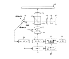
図1は本発明によるレーザ光強度制御装置を適用した光ピックアップ装置の構成を示している。この光ピックアップ装置は、半導体レーザ素子11が発するレーザビームによって光ディスク10に情報を書き込んだり、或いは光ディスク10に記録された情報を読み取るものである。光ディスク10は、例えば、DVD、DVD−R、DVD−RAM、DVD−RW、CD、CD−Rである。
【0009】
半導体レーザ素子11は2つの互いに異なる波長のレーザビームを発するものでも良い。例えば、DVD用の波長650nmのレーザビームとCD用の波長780nmのレーザビームとが後述するLDドライバ23によって選択的に発せられる。
半導体レーザ素子11から発せられたレーザビームはコリメータレンズ12を介して偏光板付きPBS(偏光ビームスプリッタ)13に平行光として到達する。PBS13の偏光板13aは半導体レーザ素子11側とは反対側、すなわち、光ディスク10側に位置するようにPBS13は配置されている。PBS13はコリメータレンズ12を介して入射したレーザビームのP偏光成分(入射面に平行な電界成分、すなわちx方向偏光成分)の大部分(例えば、90%)を通過させ、P偏光成分の一部分(例えば、10%)を偏光分離面13bで反射する。また、コリメータレンズ12を介して入射したレーザビームのS偏光成分(入射面に垂直な電界成分、すなわちy方向偏光成分)の一部分(例えば、10%)を通過させ、S偏光成分の大部分(例えば、90%)を偏光分離面13bで反射する。PBS13で反射されたレーザビームの方向は通過レーザビーム方向とほぼ垂直な方向である。偏光板13aは通過したレーザビームの直線偏光を円偏光に変換する。
【0010】
偏光板13a付きのPBS13を通過したレーザビームは対物レンズ14を介してディスク10に達してその記録面で反射される。ディスク10の記録面で反射されたレーザビームは、対物レンズ14及び偏光板13aを介してPBS13まで戻る。偏光板13aは反射されたレーザビームの円偏光を直線偏光に変換する。PBS13は戻りのレーザビームを偏光分離面13bで反射し、その反射レーザビームは集光レンズ15、マルチレンズ16を介して光検出器17の受光面に到達する。
【0011】
一方、PBS13によって反射されたレーザビームの方向にはフロントモニタ18が備えられている。フロントモニタ18は透明なアクリル平板で表面が覆われたフォトダイオードからなる。フロントモニタ18の入射面は反射レーザビームの方向に垂直ではなく、傾けられている。この傾斜角度θはレーザビームのP偏光成分に対しては上記のアクリル平板に入射し、S偏光成分を上記のアクリル平板表面で反射してしまうブルースター角度(Brewster's angle)である。よって、フロントモニタ18は入射したレーザビームの光強度に応じた電気信号、すなわちフロントモニタ信号を生成する。
【0012】
フロントモニタ18にはヘッドアンプ21を介してAPC(オートパワーコントローラ)22が接続されている。APC22はヘッドアンプ21で増幅されたフロントモニタ信号のレベルが基準レベルになるようにLDドライバ23の駆動信号レベルを制御する。基準レベルはディスク10からデータ読み取り時とディスク10へのデータ書き込み時とでは異なり、マイクロコンピュータ24によって指定される。
【0013】
書き込み時にはメモリ25から記録データが読み出され、スイッチ信号生成回路27に供給される。スイッチ信号生成回路27は記録データに応じてLDドライバ23の駆動パワーを制御する。すなわち、ディスク10にピットを形成させる部分でLDドライバ23の駆動パワーを高レベルに切り換えさせ、ピットを形成しない部分ではLDドライバ23の駆動パワーを低レベル(読み取り時の駆動パワー)に切り換えさせる。
【0014】
かかる構成の光ピックアップ装置においては、LDドライバ23の駆動信号が半導体レーザ素子11に供給され、その駆動信号レベルに応じた強度のレーザビームが半導体レーザ素子11から発射される。発射されたレーザビームのP偏光成分の一部分及びS偏光成分の大部分がPBS13で反射されて、フロントモニタ18に向かう。フロントモニタ18では上記したようにレーザビームのP偏光成分が入射し、S偏光成分は反射されてしまう。フロントモニタ18は入射したレーザビームのP偏光成分に感応し、そのP偏光成分の光強度に応じたフロントモニタ信号がフロントモニタ18から生成される。そのフロントモニタ信号はヘッドアンプ21によって増幅された後、APC22に供給される。
【0015】
APC22はフロントモニタ信号が基準レベルに等しくなるように制御信号を発生する。すなわち、フロントモニタ信号が基準レベルより低い場合には制御信号はLDドライバ23による半導体レーザ素子11に対する駆動信号レベルを増加させ、フロントモニタ信号が基準レベルより高い場合には制御信号はLDドライバ23による半導体レーザ素子11に対する駆動信号レベルを低下させる。この結果、レーザビームの偏光面の回転が起きてもPBS13を通過してディスク10に到達するレーザビームのP偏光成分を所望の強度に維持することができる。
【0016】
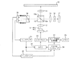
図2は本発明の他の実施例を示している。この実施例の光ピックアップ装置においては、図1の光ピックアップ装置の構成に更にS偏光用フロントモニタ31が備えられている。S偏光用フロントモニタ31は、フロントモニタ18の入射面で反射されたS偏光成分を受光するように配置されている。フロントモニタ31は入射したレーザビームの光強度に応じた電気信号、すなわちS偏光成分フロントモニタ信号を生成する。
【0017】
S偏光用フロントモニタ31はヘッドアンプ32を介してマイクロコンピュータ24に接続されている。マイクロコンピュータ24にはヘッドアンプ21の出力も接続されており、S偏光用及びP偏光用フロントモニタ信号双方が供給される。
その他の構成は図1に示した光ピックアップ装置と同様である。
【0018】
かかる図2の構成の光ピックアップ装置においては、LDドライバ23の駆動信号が半導体レーザ素子11に供給され、その駆動信号レベルに応じた強度のレーザビームが半導体レーザ素子11から発射される。発射されたレーザビームのP偏光成分の一部分及びS偏光成分の大部分がPBS13で反射されて、フロントモニタ18に向かう。フロントモニタ18では上記したようにレーザビームのP偏光成分が入射し、S偏光成分は反射されてS偏光用フロントモニタ31に向かう。フロントモニタ18からは入射したレーザビームのP偏光成分の光強度に応じたP偏光成分フロントモニタ信号が生成され、そのP偏光成分フロントモニタ信号はヘッドアンプ21によって増幅された後、APC22及びマイクロコンピュータ24に供給される。一方、S偏光用フロントモニタ31からは入射したレーザビームのS偏光成分の光強度に応じたS偏光成分フロントモニタ信号が生成され、そのS偏光成分フロントモニタ信号はヘッドアンプ21によって増幅された後、マイクロコンピュータ24に供給される。
【0019】
APC22はP偏光成分フロントモニタ信号が基準レベルに等しくなるように制御信号を発生する。すなわち、P偏光成分フロントモニタ信号が基準レベルより低い場合には制御信号はLDドライバ23による半導体レーザ素子11に対する駆動信号レベルを増加させ、P偏光成分フロントモニタ信号が基準レベルより高い場合には制御信号はLDドライバ23による半導体レーザ素子11に対する駆動信号レベルを低下させる。一方、マイクロコンピュータ24はP偏光成分フロントモニタ信号とS偏光成分フロントモニタ信号とに応じて半導体レーザ素子11による実出力レーザビームパワーを算出する。例えば、P偏光成分フロントモニタ信号の自乗値とS偏光成分フロントモニタ信号の自乗値とを加算し、その加算結果の平方根を実出力レーザビームパワーとする。
【0020】
マイクロコンピュータ24は実出力レーザビームパワーが最大定格パワーより低いリミット値に達すると、基準レベルを低下させてAPC22に対して供給する。基準レベルの低下によってAPC22から発生される制御信号はLDドライバ23による半導体レーザ素子11に対する駆動信号レベルを低下させる。この結果、P偏光成分フロントモニタ信号のみに応じた半導体レーザ素子11の出力レーザビームパワー制御のために、レーザビームの偏光面の回転時に半導体レーザ素子11が最大定格パワーを越える光強度のレーザビームを発するという不具合が回避され、半導体レーザ素子11の劣化を防止することができる。
【0021】
図3は本発明の実施例を更に示している。この実施例の光ピックアップ装置においては、図2の光ピックアップ装置の構成に更にPBS33が設けられている。PBS33はコリメータレンズ12から入射されたレーザビームをPBS13が反射する方向に配置されている。すなわち、PBS33にはPBS13からのフロントモニタ用の反射レーザビームが入射する。PBS33は入射したレーザビームのP偏光成分をほぼ100%通過させ、そのレーザビームのS偏光成分を偏光分離面33aでほぼ100%反射する。P偏光成分の反射及びS偏光成分の通過はほぼ0%である。
【0022】
PBS33をレーザビームが通過する方向には、P偏光用フロントモニタ18が備えられている。PBS33で反射されたレーザビームが進む方向には、S偏光用フロントモニタ31が備えられている。P偏光用フロントモニタ18及びS偏光用フロントモニタ31共に入射レーザビームに対して受光面が垂直となるように配置されている。
【0023】
その他の構成は図2に示した光ピックアップ装置と同様である。
かかる図3の構成の光ピックアップ装置においては、LDドライバ23の駆動信号が半導体レーザ素子11に供給され、その駆動信号レベルに応じた強度のレーザビームが半導体レーザ素子11から発射される。発射されたレーザビーム中のP偏光成分の一部分及びS偏光成分の大部分がPBS13で反射される。反射されたP偏光成分はPBS33を通過してP偏光用フロントモニタ18に向かう。一方、反射されたS偏光成分はPBS33の偏光分離面33aで反射されてS偏光用フロントモニタ31に向かう。
【0024】
フロントモニタ18では入射したレーザビームのP偏光成分の光強度に応じたP偏光成分フロントモニタ信号が生成され、そのP偏光成分フロントモニタ信号はヘッドアンプ21によって増幅された後、APC22及びマイクロコンピュータ24に供給される。一方、S偏光用フロントモニタ31からは入射したレーザビームのS偏光成分の光強度に応じたS偏光成分フロントモニタ信号が生成され、そのS偏光成分フロントモニタ信号はヘッドアンプ31によって増幅された後、マイクロコンピュータ24に供給される。APC22及びマイクロコンピュータ24の動作は上記した図2の装置の場合と同一であるので、ここでの説明は省略する。
【0025】
図4は本発明の他の実施例を更に示している。この実施例の光ピックアップ装置においては、図2の光ピックアップ装置の構成に加えてウォラストンプリズム34が設けられている。また、図2の装置に備えられたフロントモニタ18及び31に代わってフロントモニタ35が備えられている。
ウォラストンプリズム34は、コリメータレンズ12から入射されたレーザビームをPBS13が反射する方向に配置されている。すなわち、ウォラストンプリズム34にはPBS13からのフロントモニタ用の反射レーザビームが入射する。ウォラストンプリズム34は入射するレーザビームをP偏光成分とS偏光成分とに分離して互いに異なる方向に出射する。P偏光成分とS偏光成分との出射方向は入射線を中心にして対称である。
【0026】
フロントモニタ35は2分割の受光面を有して受光面毎の個別の出力を生成する。一方の受光面にはウォラストンプリズム34からP偏光成分が照射され、他方の受光面にはウォラストンプリズム34からS偏光成分が照射される。なお、フロントモニタ35に代えてP偏光用及びS偏光用フロントモニタを個別に備えても良い。
【0027】
その他の構成は図2に示した光ピックアップ装置と同様である。
かかる図4の構成の光ピックアップ装置においては、LDドライバ23の駆動信号が半導体レーザ素子11に供給され、その駆動信号レベルに応じた強度のレーザビームが半導体レーザ素子11から発射される。発射されたレーザビーム中のP偏光成分の一部分及びS偏光成分の大部分がPBS13で反射され、ウォラストンプリズム34でP偏光成分とS偏光成分とに分離される。P偏光成分はフロントモニタ35の一方の受光面に向かい、S偏光成分はフロントモニタ35の他方の受光面に向かう。
【0028】
フロントモニタ35では入射したレーザビームのP偏光成分の光強度に応じたP偏光成分フロントモニタ信号と、S偏光成分の光強度に応じたP偏光成分フロントモニタ信号とが個別に生成される。そのP偏光成分フロントモニタ信号はヘッドアンプ21によって増幅された後、APC22及びマイクロコンピュータ24に供給される。一方、S偏光成分フロントモニタ信号はヘッドアンプ31によって増幅された後、マイクロコンピュータ24に供給される。APC22及びマイクロコンピュータ24の動作は上記した図2の装置の場合と同一であるので、ここでの説明は省略する。
【0033】
なお、上記した本発明の各実施例では、光源から発せられた発散光であるレーザビームをコリメータレンズにより平行光に変換する、いわゆる無限光学系の場合について説明したが、この例に限られることなく、コリメータレンズを省いて平行光への変換を行わない有限光学系の場合であっても本発明を適用することは可能である。
【0034】
【発明の効果】
以上の如く、本発明によれば、光源から発せられるレーザビームの偏光面が回転してもそのレーザビームの光強度を簡単な構成で安定に制御することができる。
【図面の簡単な説明】
【図1】本発明の実施例を示す図である。
【図2】本発明の他の実施例を示す図である。
【図3】本発明の実施例を示す図である。
【図4】本発明の他の実施例を示す図である。
【符号の説明】
11 半導体レーザ素子
12 コリメータレンズ
13,33,36 PBS
14 対物レンズ
15 集光レンズ
16 マルチレンズ
17,37 光検出器
22 APC
24 マイクロコンピュータ
34 ウォラストンプリズム
35 フロントモニタ[0001]
[Technical field to which the invention belongs]
The present invention relates to a laser beam intensity control device applied to an optical pickup device.
[0002]
[Prior art]
In an optical pickup device used for reading information from an optical disk or writing information to a disk, a part of the laser beam emitted from the light source is monitored, and the laser beam is irradiated to the disk with an appropriate light intensity. As described above, a laser beam intensity control device is provided.
[0003]
In such a laser light intensity control device, in order to prevent a change in temperature from affecting an optical component such as a light source, the polarization plane of the laser beam rotates and the light intensity of the laser beam irradiated onto the disk is reduced. In addition, if the laser beam applied to the disk is a P-polarized component, a part of the P-polarized component in the laser beam emitted from the light source is separated by a polarizing beam splitter and received by a front monitor as a light receiving means, A light source is driven in accordance with the output signal of the front monitor (Japanese Patent Laid-Open No. 7-326064).
[0004]
[Problems to be solved by the invention]
However, the conventional laser light intensity control apparatus has a problem that the number of optical parts increases and the optical system becomes complicated.
Therefore, an object of the present invention is to provide a laser light intensity control device that can stably control the light intensity of a laser beam with a simple configuration even if the polarization plane of the laser beam emitted from the light source of the optical pickup device rotates. Is to provide.
[0005]
[Means for Solving the Problems]
The laser light intensity control device of the present invention is a laser light intensity control device that controls the light intensity of a light emitting laser beam of a light source of an optical pickup device, and is an x-direction polarization perpendicular to the traveling direction of the laser beam emitted from the light source. The polarized light separating means that passes most of the polarized light component in one of the y-direction polarized light component parallel to the traveling direction of the component and reflects a part of the polarized light component in one direction as monitor light, and reflected by the polarized light separating means A first light receiving means for receiving the monitored light and generating a first light intensity signal indicating the received light intensity; and a driving means for driving the light source in accordance with the first light intensity signal. It is characterized in that the other direction polarization component of the x direction polarization component and the y direction polarization component is reflected and does not respond to this, and one direction polarization component is absorbed and this is detected.
[0006]
The laser light intensity control device of the present invention is a laser light intensity control device that controls the light intensity of a light emitting laser beam of a light source of an optical pickup device, and is an x-direction polarization perpendicular to the traveling direction of the laser beam emitted from the light source. The most of the directional polarization component of one of the components and the y-direction polarization component parallel to the traveling direction thereof and a part of the other directional polarization component, and a part of the one directional polarization component and the other directional polarization component a first polarization separator for reflecting the majority as the monitor light, and the second polarized light separating means for separating the one direction polarization component from the monitoring light and the other direction polarization component separated by the second polarization separator The first light receiving means for receiving one directional polarization component and generating a first light intensity signal indicating the received light intensity and the other directional polarization component separated by the second polarization separation means for receiving and receiving light. Second light receiving means for generating a second light intensity signal indicating the degree of light, driving means for driving the light source in accordance with the first light intensity signal, and the actual output laser beam of the light source in accordance with the first and second light intensity signals And control means for controlling the drive means so that the actual output laser beam power is smaller than the maximum rated power of the light source.
[0008]
DETAILED DESCRIPTION OF THE INVENTION
Hereinafter, embodiments of the present invention will be described in detail with reference to the drawings.
FIG. 1 shows a configuration of an optical pickup device to which a laser light intensity control device according to the present invention is applied. This optical pickup device writes information on the
[0009]
The
A laser beam emitted from the
[0010]
The laser beam that has passed through the
[0011]
On the other hand, a
[0012]
An APC (auto power controller) 22 is connected to the
[0013]
At the time of writing, the recording data is read from the
[0014]
In the optical pickup device having such a configuration, a drive signal of the
[0015]
The
[0016]
FIG. 2 shows another embodiment of the present invention. In the optical pickup device of this embodiment, an S-polarized front monitor 31 is further provided in the configuration of the optical pickup device of FIG. The S-polarized front monitor 31 is disposed so as to receive the S-polarized light component reflected by the incident surface of the
[0017]
The S-polarized front monitor 31 is connected to the
Other configurations are the same as those of the optical pickup device shown in FIG.
[0018]
In the optical pickup device having the configuration shown in FIG. 2, the drive signal of the
[0019]
The
[0020]
When the actual output laser beam power reaches a limit value lower than the maximum rated power, the
[0021]
FIG. 3 further illustrates an embodiment of the present invention. In the optical pickup device of this embodiment, a
[0022]
A P-polarized front monitor 18 is provided in the direction in which the laser beam passes through the
[0023]
Other configurations are the same as those of the optical pickup device shown in FIG.
In the optical pickup device having the configuration shown in FIG. 3, the drive signal of the
[0024]
The
[0025]
FIG. 4 further illustrates another embodiment of the present invention. In the optical pickup device of this embodiment, a Wollaston prism 34 is provided in addition to the configuration of the optical pickup device of FIG. Further, a
The Wollaston prism 34 is arranged in a direction in which the
[0026]
The
[0027]
Other configurations are the same as those of the optical pickup device shown in FIG.
In the optical pickup device having the configuration shown in FIG. 4, the drive signal of the
[0028]
The
[0033]
In each of the embodiments of the present invention described above, a case of a so-called infinite optical system in which a laser beam, which is a divergent light emitted from a light source, is converted into parallel light by a collimator lens has been described. However, the present invention is limited to this example. In addition, the present invention can be applied even in the case of a finite optical system in which the collimator lens is omitted and conversion into parallel light is not performed.
[0034]
【The invention's effect】
As described above, according to the present invention, even if the polarization plane of the laser beam emitted from the light source rotates, the light intensity of the laser beam can be stably controlled with a simple configuration.
[Brief description of the drawings]
FIG. 1 is a diagram showing an embodiment of the present invention.
FIG. 2 is a diagram showing another embodiment of the present invention.
FIG. 3 is a diagram showing an embodiment of the present invention.
FIG. 4 is a diagram showing another embodiment of the present invention.
[Explanation of symbols]
11
14
24 Microcomputer 34
Claims (13)
前記光源から発せられたレーザビームの進行方向に垂直なx方向偏光成分及びその進行方向に平行なy方向偏光成分のいずれか一方の方向偏光成分の大部分を通過させその一方の方向偏光成分の一部分をモニタ光として反射する偏光分離手段と、
前記偏光分離手段によって反射された前記モニタ光を受光して受光強度を示す第1光強度信号を生成する第1受光手段と、
前記第1光強度信号に応じて前記光源を駆動する駆動手段と、を備え、
前記第1受光手段は前記x方向偏光成分及び前記y方向偏光成分の他方の方向偏光成分を反射してこれに感応せず、前記一方の方向偏光成分を吸収してこれに感応することを特徴とするレーザ光強度制御装置。A laser light intensity control device for controlling the light intensity of a light emitting laser beam of a light source of an optical pickup device,
Passing most of one of the directional polarization components of the x direction polarization component perpendicular to the traveling direction of the laser beam emitted from the light source and the y direction polarization component parallel to the traveling direction of the one direction polarization component Polarized light separating means for reflecting a part of the light as monitor light;
First light receiving means for receiving the monitor light reflected by the polarization separating means and generating a first light intensity signal indicating the received light intensity;
Driving means for driving the light source in accordance with the first light intensity signal,
The first light receiving means reflects the other directional polarization component of the x-direction polarization component and the y-direction polarization component and does not respond thereto, and absorbs and responds to the one directional polarization component. A laser light intensity control device.
前記第1受光手段によって反射された前記他方の方向偏光成分を受光して受光強度を示す第2光強度信号を生成する第2受光手段と、
前記第1及び第2光強度信号に応じて前記光源の実出力レーザビームパワーを算出してその実出力レーザビームパワーが前記光源の最大定格パワーより小さくなるように前記駆動手段を制御する制御手段と、を含むことを特徴とする請求項2記載のレーザ光強度制御装置。The polarization separation means reflects a majority of the other direction polarization component in the output parallel beam of the conversion means in the direction of the monitor light and passes a part of the other direction polarization component;
Second light receiving means for receiving the other directional polarization component reflected by the first light receiving means and generating a second light intensity signal indicating the received light intensity;
Control means for calculating an actual output laser beam power of the light source according to the first and second light intensity signals and controlling the driving means so that the actual output laser beam power is smaller than a maximum rated power of the light source; The laser light intensity control device according to claim 2, wherein
前記光源から発せられたレーザビームの進行方向に垂直なx方向偏光成分及びその進行方向に平行なy方向偏光成分のいずれか一方の方向偏光成分の大部分と他方の方向偏光成分の一部分とを通過させその一方の方向偏光成分の一部分と他方の方向偏光成分の大部分とをモニタ光として反射する第1偏光分離手段と、
前記モニタ光から前記一方の方向偏光成分と前記他方の方向偏光成分とを分離する第2偏光分離手段と、
前記第2偏光分離手段によって分離された前記一方の方向偏光成分を受光して受光強度を示す第1光強度信号を生成する第1受光手段と、
前記第2偏光分離手段によって分離された前記他方の方向偏光成分を受光して受光強度を示す第2光強度信号を生成する第2受光手段と、
前記第1光強度信号に応じて前記光源を駆動する駆動手段と、
前記第1及び第2光強度信号に応じて前記光源の実出力レーザビームパワーを算出してその実出力レーザビームパワーが前記光源の最大定格パワーより小さくなるように前記駆動手段を制御する制御手段と、を備えたことを特徴とするレーザ光強度制御装置。A laser light intensity control device for controlling the light intensity of a light emitting laser beam of a light source of an optical pickup device,
Most of one direction polarization component of the x direction polarization component perpendicular to the traveling direction of the laser beam emitted from the light source and y direction polarization component parallel to the traveling direction, and a part of the other direction polarization component. First polarization separation means for passing and reflecting a part of the one direction polarization component and a majority of the other direction polarization component as monitor light;
Second polarization separation means for separating the one direction polarization component and the other direction polarization component from the monitor light;
First light receiving means for receiving the one-direction polarized light component separated by the second polarization separation means and generating a first light intensity signal indicating the received light intensity;
Second light receiving means for receiving the other directional polarization component separated by the second polarized light separating means and generating a second light intensity signal indicating the received light intensity;
Driving means for driving the light source in response to the first light intensity signal;
Control means for calculating an actual output laser beam power of the light source according to the first and second light intensity signals and controlling the driving means so that the actual output laser beam power is smaller than a maximum rated power of the light source; And a laser beam intensity control device.
Priority Applications (3)
| Application Number | Priority Date | Filing Date | Title |
|---|---|---|---|
| JP2000303075A JP4157265B2 (en) | 2000-10-03 | 2000-10-03 | Laser intensity control device |
| EP01123680A EP1195751A3 (en) | 2000-10-03 | 2001-10-02 | Laser light intensity controller |
| US09/968,907 US6731662B2 (en) | 2000-10-03 | 2001-10-03 | Laser light intensity controller |
Applications Claiming Priority (1)
| Application Number | Priority Date | Filing Date | Title |
|---|---|---|---|
| JP2000303075A JP4157265B2 (en) | 2000-10-03 | 2000-10-03 | Laser intensity control device |
Publications (3)
| Publication Number | Publication Date |
|---|---|
| JP2002109773A JP2002109773A (en) | 2002-04-12 |
| JP2002109773A5 JP2002109773A5 (en) | 2005-11-04 |
| JP4157265B2 true JP4157265B2 (en) | 2008-10-01 |
Family
ID=18784328
Family Applications (1)
| Application Number | Title | Priority Date | Filing Date |
|---|---|---|---|
| JP2000303075A Expired - Fee Related JP4157265B2 (en) | 2000-10-03 | 2000-10-03 | Laser intensity control device |
Country Status (3)
| Country | Link |
|---|---|
| US (1) | US6731662B2 (en) |
| EP (1) | EP1195751A3 (en) |
| JP (1) | JP4157265B2 (en) |
Families Citing this family (4)
| Publication number | Priority date | Publication date | Assignee | Title |
|---|---|---|---|---|
| JP2003204112A (en) * | 2002-01-09 | 2003-07-18 | Oki Electric Ind Co Ltd | Semiconductor laser module |
| JP4155166B2 (en) * | 2003-11-10 | 2008-09-24 | コニカミノルタオプト株式会社 | Optical pickup device |
| JP5046939B2 (en) | 2005-08-30 | 2012-10-10 | パナソニック株式会社 | Optical pickup device |
| JP2010182381A (en) * | 2009-02-06 | 2010-08-19 | Victor Co Of Japan Ltd | Optical pickup device |
Family Cites Families (16)
| Publication number | Priority date | Publication date | Assignee | Title |
|---|---|---|---|---|
| JPH0614570B2 (en) * | 1987-04-28 | 1994-02-23 | シャープ株式会社 | Optical output stabilizing method and photodetector used in the method |
| US4984229A (en) * | 1988-11-18 | 1991-01-08 | Polaroid Corporation | Autofocus system |
| US5544144A (en) * | 1990-11-14 | 1996-08-06 | Asahi Kogaku Kogyo Kabushiki Kaisha | Optical head structure having compactly arranged parts |
| US5274491A (en) * | 1991-05-13 | 1993-12-28 | Ncr Corporation | Dynamic laser diode aperture for optical scanners |
| US5233175A (en) * | 1992-08-24 | 1993-08-03 | International Business Machines Corporation | Laser power control independent of beamsplitter transmissivity |
| JP3239962B2 (en) * | 1992-09-10 | 2001-12-17 | キヤノン株式会社 | Optical information recording / reproducing device |
| JP3244893B2 (en) * | 1993-11-26 | 2002-01-07 | キヤノン株式会社 | Optical recording / reproducing device |
| US5604592A (en) * | 1994-09-19 | 1997-02-18 | Textron Defense Systems, Division Of Avco Corporation | Laser ultrasonics-based material analysis system and method using matched filter processing |
| US5519679A (en) * | 1994-10-12 | 1996-05-21 | Eastman Kodak Company | Apparatus and method for multi-spot sampled tracking in an optical data storage system |
| US5561655A (en) * | 1994-12-02 | 1996-10-01 | Eastman Kodak Company | Apparatus and method for differential tracking in a magneto-optic data storage system using mark edge detection |
| US5657307A (en) * | 1995-03-10 | 1997-08-12 | Sharp Kabushiki Kaisha | Optical data reading apparatus and method |
| US5796511A (en) * | 1996-08-30 | 1998-08-18 | Agfa Division, Bayer Corporation | Multi-beam scanner with acousto-optic element for scanning imaging surfaces |
| JPH10222863A (en) * | 1996-12-06 | 1998-08-21 | Pioneer Electron Corp | Optical pickup device |
| JP2000200450A (en) * | 1998-10-30 | 2000-07-18 | Canon Inc | Magneto-optical recording and reproducing method and its device |
| JP3519304B2 (en) * | 1999-02-25 | 2004-04-12 | シャープ株式会社 | Magneto-optical head, magneto-optical device, and magneto-optical recording / reproducing method |
| JP2002185073A (en) * | 2000-10-04 | 2002-06-28 | Pioneer Electronic Corp | Laser light intensity controller |
-
2000
- 2000-10-03 JP JP2000303075A patent/JP4157265B2/en not_active Expired - Fee Related
-
2001
- 2001-10-02 EP EP01123680A patent/EP1195751A3/en not_active Withdrawn
- 2001-10-03 US US09/968,907 patent/US6731662B2/en not_active Expired - Fee Related
Also Published As
| Publication number | Publication date |
|---|---|
| EP1195751A3 (en) | 2004-06-16 |
| US6731662B2 (en) | 2004-05-04 |
| JP2002109773A (en) | 2002-04-12 |
| EP1195751A2 (en) | 2002-04-10 |
| US20020044577A1 (en) | 2002-04-18 |
Similar Documents
| Publication | Publication Date | Title |
|---|---|---|
| JP3407893B2 (en) | Semiconductor laser controller | |
| JP4157265B2 (en) | Laser intensity control device | |
| US6697398B2 (en) | Laser light intensity controller | |
| KR100882301B1 (en) | A laser diode·driver and n-wavelength associated optical pickup with this | |
| KR100699809B1 (en) | Optical pickup apparatus | |
| US20050281170A1 (en) | Optical pickup device | |
| JPH04349236A (en) | Optical pick-up device | |
| JP2006309850A (en) | Optical head device and information recording and reproducing apparatus | |
| JP2006309851A (en) | Optical head device and information recording and reproducing device | |
| JP2002216385A (en) | Optical pickup device and optical information processing device | |
| JP2002319699A (en) | Optical device | |
| JP4008784B2 (en) | Optical pickup device | |
| JP2000020997A (en) | Optical pickup device | |
| JPH0521883A (en) | Output control device | |
| JP2004071073A (en) | Optical pickup device | |
| US6985421B2 (en) | Optical device having a light emission unit emitting a light beam reflected by a light reflection unit to a substrate, and optical information recording apparatus using the same | |
| JP2001202651A (en) | Optical pickup device and optical disk device | |
| JP3564883B2 (en) | Optical pickup device | |
| JP2003228868A (en) | Optical head device and optical disk drive | |
| KR100497380B1 (en) | Light emitting module and optical pickup apparatus adopting the same | |
| JP2008176823A (en) | Optical disk recording and playback device | |
| JP2000182253A (en) | Information recording and reproducing device | |
| JP2003030888A (en) | Optical pickup device | |
| JPH01125738A (en) | Optical head | |
| JP2004030895A (en) | Optical pickup provided with monitor light detector |
Legal Events
| Date | Code | Title | Description |
|---|---|---|---|
| A521 | Written amendment |
Free format text: JAPANESE INTERMEDIATE CODE: A523 Effective date: 20050912 |
|
| A621 | Written request for application examination |
Free format text: JAPANESE INTERMEDIATE CODE: A621 Effective date: 20050912 |
|
| A977 | Report on retrieval |
Free format text: JAPANESE INTERMEDIATE CODE: A971007 Effective date: 20080324 |
|
| A131 | Notification of reasons for refusal |
Free format text: JAPANESE INTERMEDIATE CODE: A131 Effective date: 20080422 |
|
| A521 | Written amendment |
Free format text: JAPANESE INTERMEDIATE CODE: A523 Effective date: 20080617 |
|
| TRDD | Decision of grant or rejection written | ||
| A01 | Written decision to grant a patent or to grant a registration (utility model) |
Free format text: JAPANESE INTERMEDIATE CODE: A01 Effective date: 20080708 |
|
| A01 | Written decision to grant a patent or to grant a registration (utility model) |
Free format text: JAPANESE INTERMEDIATE CODE: A01 |
|
| A61 | First payment of annual fees (during grant procedure) |
Free format text: JAPANESE INTERMEDIATE CODE: A61 Effective date: 20080711 |
|
| FPAY | Renewal fee payment (event date is renewal date of database) |
Free format text: PAYMENT UNTIL: 20110718 Year of fee payment: 3 |
|
| R150 | Certificate of patent or registration of utility model |
Free format text: JAPANESE INTERMEDIATE CODE: R150 |
|
| LAPS | Cancellation because of no payment of annual fees |