JP4156195B2 - 3-axis coil sensor - Google Patents
3-axis coil sensor Download PDFInfo
- Publication number
- JP4156195B2 JP4156195B2 JP2000540755A JP2000540755A JP4156195B2 JP 4156195 B2 JP4156195 B2 JP 4156195B2 JP 2000540755 A JP2000540755 A JP 2000540755A JP 2000540755 A JP2000540755 A JP 2000540755A JP 4156195 B2 JP4156195 B2 JP 4156195B2
- Authority
- JP
- Japan
- Prior art keywords
- field
- transducer
- probe
- patient
- transducers
- Prior art date
- Legal status (The legal status is an assumption and is not a legal conclusion. Google has not performed a legal analysis and makes no representation as to the accuracy of the status listed.)
- Expired - Lifetime
Links
- 239000000523 sample Substances 0.000 claims description 135
- 239000000758 substrate Substances 0.000 claims description 33
- 230000000712 assembly Effects 0.000 claims description 25
- 238000000429 assembly Methods 0.000 claims description 25
- 230000005291 magnetic effect Effects 0.000 claims description 20
- 238000010438 heat treatment Methods 0.000 claims description 2
- 230000002093 peripheral effect Effects 0.000 claims description 2
- 238000000034 method Methods 0.000 description 35
- 230000008569 process Effects 0.000 description 18
- 238000012545 processing Methods 0.000 description 11
- 239000010410 layer Substances 0.000 description 8
- 239000003550 marker Substances 0.000 description 8
- 238000004364 calculation method Methods 0.000 description 6
- 239000000463 material Substances 0.000 description 6
- 238000005259 measurement Methods 0.000 description 6
- 230000003287 optical effect Effects 0.000 description 6
- 239000000853 adhesive Substances 0.000 description 5
- 230000001070 adhesive effect Effects 0.000 description 5
- 230000008901 benefit Effects 0.000 description 5
- 230000005672 electromagnetic field Effects 0.000 description 5
- 230000005540 biological transmission Effects 0.000 description 4
- 210000000038 chest Anatomy 0.000 description 4
- 238000004891 communication Methods 0.000 description 3
- 229910052751 metal Inorganic materials 0.000 description 3
- 239000002184 metal Substances 0.000 description 3
- 230000005355 Hall effect Effects 0.000 description 2
- 210000003484 anatomy Anatomy 0.000 description 2
- 230000000747 cardiac effect Effects 0.000 description 2
- 239000011248 coating agent Substances 0.000 description 2
- 238000000576 coating method Methods 0.000 description 2
- 239000004020 conductor Substances 0.000 description 2
- 238000001816 cooling Methods 0.000 description 2
- 230000005294 ferromagnetic effect Effects 0.000 description 2
- 239000003302 ferromagnetic material Substances 0.000 description 2
- 238000002594 fluoroscopy Methods 0.000 description 2
- 238000003384 imaging method Methods 0.000 description 2
- 230000005865 ionizing radiation Effects 0.000 description 2
- 238000002595 magnetic resonance imaging Methods 0.000 description 2
- 230000007246 mechanism Effects 0.000 description 2
- 150000002739 metals Chemical class 0.000 description 2
- 229920000642 polymer Polymers 0.000 description 2
- 230000004044 response Effects 0.000 description 2
- 230000035945 sensitivity Effects 0.000 description 2
- 239000007787 solid Substances 0.000 description 2
- 210000001519 tissue Anatomy 0.000 description 2
- 239000004642 Polyimide Substances 0.000 description 1
- 210000001015 abdomen Anatomy 0.000 description 1
- 230000003213 activating effect Effects 0.000 description 1
- 238000004026 adhesive bonding Methods 0.000 description 1
- 239000012790 adhesive layer Substances 0.000 description 1
- 239000002390 adhesive tape Substances 0.000 description 1
- 229910052782 aluminium Inorganic materials 0.000 description 1
- XAGFODPZIPBFFR-UHFFFAOYSA-N aluminium Chemical compound [Al] XAGFODPZIPBFFR-UHFFFAOYSA-N 0.000 description 1
- 238000013459 approach Methods 0.000 description 1
- 238000005452 bending Methods 0.000 description 1
- 238000001574 biopsy Methods 0.000 description 1
- 210000000746 body region Anatomy 0.000 description 1
- 230000036760 body temperature Effects 0.000 description 1
- 210000000988 bone and bone Anatomy 0.000 description 1
- 210000004556 brain Anatomy 0.000 description 1
- 238000012790 confirmation Methods 0.000 description 1
- 239000000470 constituent Substances 0.000 description 1
- 238000007796 conventional method Methods 0.000 description 1
- 239000002826 coolant Substances 0.000 description 1
- 230000008878 coupling Effects 0.000 description 1
- 238000010168 coupling process Methods 0.000 description 1
- 238000005859 coupling reaction Methods 0.000 description 1
- 238000007428 craniotomy Methods 0.000 description 1
- 238000010586 diagram Methods 0.000 description 1
- 230000000694 effects Effects 0.000 description 1
- 230000005670 electromagnetic radiation Effects 0.000 description 1
- 230000002708 enhancing effect Effects 0.000 description 1
- 230000008713 feedback mechanism Effects 0.000 description 1
- 239000012212 insulator Substances 0.000 description 1
- 230000002452 interceptive effect Effects 0.000 description 1
- 238000010030 laminating Methods 0.000 description 1
- 238000012830 laparoscopic surgical procedure Methods 0.000 description 1
- WABPQHHGFIMREM-UHFFFAOYSA-N lead(0) Chemical compound [Pb] WABPQHHGFIMREM-UHFFFAOYSA-N 0.000 description 1
- 238000013507 mapping Methods 0.000 description 1
- 238000000968 medical method and process Methods 0.000 description 1
- 238000012544 monitoring process Methods 0.000 description 1
- 229920001721 polyimide Polymers 0.000 description 1
- 238000007639 printing Methods 0.000 description 1
- 238000003672 processing method Methods 0.000 description 1
- 230000002035 prolonged effect Effects 0.000 description 1
- 230000005855 radiation Effects 0.000 description 1
- 230000029058 respiratory gaseous exchange Effects 0.000 description 1
- 230000002441 reversible effect Effects 0.000 description 1
- 238000005070 sampling Methods 0.000 description 1
- 210000004872 soft tissue Anatomy 0.000 description 1
- 238000004659 sterilization and disinfection Methods 0.000 description 1
- 239000000126 substance Substances 0.000 description 1
- 230000001225 therapeutic effect Effects 0.000 description 1
- 238000002560 therapeutic procedure Methods 0.000 description 1
- 238000003325 tomography Methods 0.000 description 1
- 238000012546 transfer Methods 0.000 description 1
- 238000002604 ultrasonography Methods 0.000 description 1
- 238000009423 ventilation Methods 0.000 description 1
- XLYOFNOQVPJJNP-UHFFFAOYSA-N water Substances O XLYOFNOQVPJJNP-UHFFFAOYSA-N 0.000 description 1
- 238000004804 winding Methods 0.000 description 1
Images


Classifications
-
- H—ELECTRICITY
- H01—ELECTRIC ELEMENTS
- H01F—MAGNETS; INDUCTANCES; TRANSFORMERS; SELECTION OF MATERIALS FOR THEIR MAGNETIC PROPERTIES
- H01F5/00—Coils
-
- A—HUMAN NECESSITIES
- A61—MEDICAL OR VETERINARY SCIENCE; HYGIENE
- A61B—DIAGNOSIS; SURGERY; IDENTIFICATION
- A61B34/00—Computer-aided surgery; Manipulators or robots specially adapted for use in surgery
- A61B34/20—Surgical navigation systems; Devices for tracking or guiding surgical instruments, e.g. for frameless stereotaxis
-
- A—HUMAN NECESSITIES
- A61—MEDICAL OR VETERINARY SCIENCE; HYGIENE
- A61B—DIAGNOSIS; SURGERY; IDENTIFICATION
- A61B5/00—Measuring for diagnostic purposes; Identification of persons
- A61B5/06—Devices, other than using radiation, for detecting or locating foreign bodies ; determining position of probes within or on the body of the patient
- A61B5/061—Determining position of a probe within the body employing means separate from the probe, e.g. sensing internal probe position employing impedance electrodes on the surface of the body
- A61B5/062—Determining position of a probe within the body employing means separate from the probe, e.g. sensing internal probe position employing impedance electrodes on the surface of the body using magnetic field
-
- A—HUMAN NECESSITIES
- A61—MEDICAL OR VETERINARY SCIENCE; HYGIENE
- A61B—DIAGNOSIS; SURGERY; IDENTIFICATION
- A61B17/00—Surgical instruments, devices or methods, e.g. tourniquets
- A61B17/28—Surgical forceps
- A61B17/29—Forceps for use in minimally invasive surgery
- A61B2017/2901—Details of shaft
- A61B2017/2905—Details of shaft flexible
-
- A—HUMAN NECESSITIES
- A61—MEDICAL OR VETERINARY SCIENCE; HYGIENE
- A61B—DIAGNOSIS; SURGERY; IDENTIFICATION
- A61B34/00—Computer-aided surgery; Manipulators or robots specially adapted for use in surgery
- A61B34/20—Surgical navigation systems; Devices for tracking or guiding surgical instruments, e.g. for frameless stereotaxis
- A61B2034/2046—Tracking techniques
- A61B2034/2051—Electromagnetic tracking systems
-
- A—HUMAN NECESSITIES
- A61—MEDICAL OR VETERINARY SCIENCE; HYGIENE
- A61B—DIAGNOSIS; SURGERY; IDENTIFICATION
- A61B34/00—Computer-aided surgery; Manipulators or robots specially adapted for use in surgery
- A61B34/20—Surgical navigation systems; Devices for tracking or guiding surgical instruments, e.g. for frameless stereotaxis
- A61B2034/2072—Reference field transducer attached to an instrument or patient
-
- A—HUMAN NECESSITIES
- A61—MEDICAL OR VETERINARY SCIENCE; HYGIENE
- A61B—DIAGNOSIS; SURGERY; IDENTIFICATION
- A61B90/00—Instruments, implements or accessories specially adapted for surgery or diagnosis and not covered by any of the groups A61B1/00 - A61B50/00, e.g. for luxation treatment or for protecting wound edges
- A61B90/39—Markers, e.g. radio-opaque or breast lesions markers
- A61B2090/3983—Reference marker arrangements for use with image guided surgery
Landscapes
- Health & Medical Sciences (AREA)
- Life Sciences & Earth Sciences (AREA)
- Engineering & Computer Science (AREA)
- Surgery (AREA)
- Veterinary Medicine (AREA)
- General Health & Medical Sciences (AREA)
- Public Health (AREA)
- Biomedical Technology (AREA)
- Heart & Thoracic Surgery (AREA)
- Medical Informatics (AREA)
- Molecular Biology (AREA)
- Animal Behavior & Ethology (AREA)
- Physics & Mathematics (AREA)
- Biophysics (AREA)
- Pathology (AREA)
- Human Computer Interaction (AREA)
- Nuclear Medicine, Radiotherapy & Molecular Imaging (AREA)
- Robotics (AREA)
- Power Engineering (AREA)
- Measurement Of Length, Angles, Or The Like Using Electric Or Magnetic Means (AREA)
- Magnetic Resonance Imaging Apparatus (AREA)
- Measurement And Recording Of Electrical Phenomena And Electrical Characteristics Of The Living Body (AREA)
- Ultra Sonic Daignosis Equipment (AREA)
Description
【0001】
【技術分野】
本発明は医療診断および治療用のシステムに関し、特に、患者の体内における位置、配向、またはこれらの両方を検出するための基準フィールド・トランスデューサおよびプローブ・フィールド・トランスデューサを用いる医療プローブの使用に関する。
【0002】
【背景技術】
被験体または患者の体内にカテーテルのようなプローブを導入する医療方法が多くある。心臓カテーテル処理および神経外科手術のような処置において、医者や外科医は体内におけるプローブの先端部の位置を知ることが必要である場合が多い。この目的のためにX線透視法や超音波のような画像処理方法が使用される場合があるが、これらの方法が常に実用的または望ましいとは限らない。例えば、これらのシステムは一般に処理中にプローブおよび患者の継続的な画像処理を必要とする。加えて、X線透視システムは患者や医者を相当なイオン化性放射線に暴露するために望ましくない場合が多い。
【0003】
患者の継続的な画像処理を必要とせずに患者の体内におけるプローブまたはカテーテルの先端部の位置を検出するための多くの位置決めシステムが提案されている。例えば、これらのシステムは本明細書に参考文献として含まれる米国特許第5,558,091号、同第5,391,199号、同第5,443,489号、および特許出願公開第WO 94/04938号および同第WO 96/05768号に開示されているものを含む。また、必ずしも医療用途ではない別の電磁追跡システムが米国特許3,644,825号、同第3,868,565号、同第4,017,858号、同第4,054,881号および同第4,849,692号に記載されている。
【0004】
上記の米国特許第5,558,091号、同第5,391,199号および同第5,443,489号、および特許出願公開第WO 94/04938号はホール効果(Hall effect)装置、磁気抵抗装置、プローブを担持するコイルまたは別のアンテナのような1個以上のフィールド・トランスデューサを用いるプローブの位置(すなわち、位置、配向、またはこれらの両方)を決定する。これらのトランスデューサは一般にプローブの先端部またはこの近くに配置されるか、プローブの先端部に対して正確に知られた位置に配置されている。このようなシステムはさらに基準の外部フレームを得るために体の外側に配置される1個以上の基準フィールド・トランスデューサを利用している。これらの基準フィールド・トランスデューサは非イオン化性の場または磁場、電磁放射線または超音波振動のような音響エネルギーのような場の成分を伝送して検出するように動作する。外部基準フィールド・トランスデューサとプローブ・フィールド・トランスデューサとの間に場を伝送することにより、これらの装置の間における場(field)の伝送の特性が決定できて、基準の外部フレームにおけるプローブの位置および配向を決定するために使用できる。
【0005】
例えば、上記米国特許第5,558,091号に記載されるように、外部フィールド・トランスデューサの基準のフレームは磁気共鳴画像処理データ、コンピュータ処理化軸方向断層X線撮影(「CAT」)データ、または従来的なX線画像処理データのような画像データの基準のフレームと共に整合できるので、このシステムから得られる位置および/または配向データは患者の身体の画像に重ね合わせたプローブの表現として表示できる。医者はこの情報を用いてプローブを患者の体内の所望の位置に案内して、治療およびその体内構造の測定中にプローブの位置および配向をモニターできる。このような構成は体内構造中におけるプローブの先端部を操縦する医者の能力を大幅に高めると共に、感触のみにより体内のプローブを操縦する従来の方法よりも優れた利点を有している。このシステムは操縦の目的のために周囲組織の光学画像を得る必要がないので、光学素子に適応するには小さすぎるプローブと共に使用できる。さらに、これらのトランスデューサを基本とするシステムは処理中におけるプローブおよび患者の継続的な画像処理によるプローブの操縦に伴う困難さを回避することができ、例えば、X線透視システムにおいて固有のイオン化性放射線への長時間の暴露を回避できる。
【0006】
このようなシステムは一般に基準フィールド・トランスデューサまたはコイルを使用しており、これらの素子は手術室の天井のような場所において固定した移動不能なアレイ状に備え付けられるか、手術用またはカテーテル処理用のテーブルに固定される。このシステムが患者の体内のプローブの場所を追跡するために使用される医療用途においては、上記のコイルの取り付けが医者の患者に対する自由な接近を妨害することが起こり得る。
【0007】
例えば、上記特許出願公開第WO 94/04938号はカテーテルの先端部の近くにおいて複数の非同心円状のコイルを使用するカテーテル・システムを記載している。これらのコイルは外部から供給された磁場に応じて信号を発生し、このことにより6種類の位置および配向の座標の計算が可能になり、同時的な画像処理を必要とすることなくカテーテルの配置を知ることができる。好ましくは、少なくとも3個のこのようなコイルまたは放射体を、カテーテルを導入する身体領域の近くにおける体外の固定した場所に配列する。例えば、心臓のカテーテル処理において、この処理中に患者は一般に背臥状態であり、3個の放射体が一般に患者の胸部の下方に固定した同一平面内に三角形状の配列で固定配置されていて、各コイルの中心が約2cm乃至40cm離れている。また、脳内に挿入したカテーテルまたはプローブの位置および配向を決定する場合は、上記のトランスデューサまたはフィールド放射コイルを患者の頭部の近くに配置することが望ましい。しかしながら、神経外科手術においては、患者は座っていたり、直立状態であったり、下向きの場合がある。それゆえ、上記のような3個の放射体を保持する三角形のフレームは頭部の下方に使用感良く安定に配置することができない。しかしながら、このフレームを頭部の上方または側方に配置することは一般に外科医のプローブおよび手術器具の操作を妨害する。
【0008】
それゆえ、上記の基準フィールド・トランスデューサの配置を調節および最適化することにより、上記のプローブ追跡システムおよび人体に対して電磁場またはその他の非イオン化性のエネルギーの場を供給することに関するその他のシステムの精度および有効性を高めることが望まれている。このようなトランスデューサの配置を柔軟に行うことにより、位置決めシステムの感度を増加する最良の可能な位置に各トランスデューサを移動して個々の場合に適応したトランスデューサの配置が可能になる。
【0009】
【発明の開示】
本発明の態様の一例は患者の体内におけるプローブの配置を決定するためのシステムを提供する。本発明のこの態様に従うシステムは1個以上のプローブ・フィールド・トランスデューサを取り付けたプローブを備えているのが望ましい。さらに、1個以上の基準フィールド・トランスデューサが備えられている。この開示において使用される用語の「フィールド・トランスデューサ(field transducer)」は磁場、電磁場、音響または光学的な場(field)のような非イオン化性の場を伝送できる装置を含み、このような場の1個以上の成分を検出できる装置も含む。本発明のこの態様に従うシステムにおいて、基準フィールド・トランスデューサは互いに独立して移動可能であり、使用者により患者の身体に対して所望の、使用者により選択された、個々の場合に適応できる場所に位置決めできる。最も好ましくは、このシステムは基準フィールド・トランスデューサを患者の身体上に取り付けるための手段を備えている。特に好ましい配列構成において、これらの基準フィールド・トランスデューサは互いに機械的に接触することがなく、各基準フィールド・トランスデューサは他の基準フィールド・トランスデューサの配置による機械的な拘束を受けることなく使用者により所望の任意の位置に配置できる。さらに校正手段(calibration means)が備えられていて、当該手段は、例えば、基準フィールド・トランスデューサが患者の身体上に取り付けられている等、基準フィールド・トランスデューサが所望の位置に配置されている間に当該フィールド・トランスデューサの互いの相対的配置を決定する。単一の目的物についてこの開示において使用する用語の「配置(disposition)」は当該目的物の位置、目的物の配向、またはこれらの両方を意味する。また、任意の2個の目的物についてこの開示において使用する用語の「相対的配置(relative disposition)」は1個の目的物から他の目的物までの方向、1個の目的物から他の目的物までの距離、またはこれらの両方を意味し、各目的物の基準のフレーム内における他の目的物の配向も含む。最も好ましくは、上記校正手段は各フィールド・トランスデューサの互いに対する相対配置の全てのパラメータを完全に決定するように配列構成されていて、各フィールド・トランスデューサから他の各フィールド・トランスデューサまでの距離および方向、全てのフィールド・トランスデューサの配向が完全に分かるようになっている。
【0010】
このシステムはさらに基準フィールド・トランスデューサおよびプローブ・フィールド・トランスデューサを駆動して当該基準フィールド・トランスデューサと伝送される各場を検出する1個以上のプローブ・フィールド・トランスデューサとの間に1種類以上の非イオン化性の場を伝送するための伝送手段を備えている。例えば、この伝送手段が基準フィールド・トランスデューサを駆動して磁場または電磁場を伝送する場合に、プローブ・フィールド・トランスデューサが1個以上のプローブ・フィールド・トランスデューサにおいて受信される場の特性を検出する。さらに、基準フィールド・トランスデューサの基準のフレームにおけるプローブの配置を決定するために計算手段が備えられている。この計算は検出した場の特性および基準フィールド・トランスデューサの互いに対する相対配置に基づいて行われる。
【0011】
上記の基準フィールド・トランスデューサは患者の身体上またはその近くに独立して配置可能であるので、これらを最適な配列構成に配置して特定の処理中にプローブを配置する必要のある特定関与領域内の良好な感度および信号−ノイズ比を得ることができる。さらに、上記の基準フィールド・トランスデューサ位置決めが外科手術またはその他の医療処理のための接近行為を妨げないように選択できる。後にさらに説明するが、基準フィールド・トランスデューサにより定められた基準のフレームは既に得られた画像の基準のフレームに整合可能であり、プローブの表現はこの既に得られた画像に重ね合わせて表示できる。基準フィールド・トランスデューサが患者の身体上に取り付けられている好ましい実施形態において、これらの基準フィールド・トランスデューサにより定められる基準のフレームは患者と共に移動する。それゆえ、既に得られた画像との整合は患者の移動に関わらず調節や再整合を要することなく維持できる。本発明の別の実施形態によるシステムにおいては、上記の校正手段および計算手段が基準フィールド・トランスデューサの相対配置を周期的に再決定し、プローブの配置を当該再決定された基準フィールド・トランスデューサの相対配置に基づいて再決定するように配列構成されている。例えば、このシステムが周期的に動作して、各周期が基準フィールド・トランスデューサの相対配置の再決定処理およびプローブ配置の決定処理を含んでいる。言い換えれば、基準フィールド・トランスデューサの基準のフレームがプローブ配置の各測定処理の前に更新される。あるいは、基準フィールド・トランスデューサの配置が周期的に更新できる。これらのシステムは基準フィールド・トランスデューサの、例えば腹部または胸郭の表面上等の、身体における移動可能な要素の上への取り付けを可能にする。
【0012】
上記の校正手段は1個以上の基準フィールド・トランスデューサに取り付けた1個以上の校正フィールド・トランスデューサを備えていてもよい。これにより、1個以上の基準フィールド・トランスデューサが1個以上の校正フィールド・トランスデューサとの基準組立体の状態で備え付けられる。この校正手段は、例えば別の基準組立体の基準トランスデューサから伝送された場として、各校正フィールド・トランスデューサに、または、各校正フィールド・トランスデューサから伝送される非イオン化性の場を検出することにより、基準フィールド・トランスデューサの相対配置を決定するように配列構成されている。
【0013】
本発明の別の態様は患者の体内におけるプローブの配置を決定する方法を提供する。望ましくは、本発明のこの態様による方法は1個以上のプローブ・フィールド・トランスデューサを有する前述のようなプローブを備える工程と、使用者により選択された個々の患者の身体の必要性に対応する位置に、必要に応じて互いに対して独立して位置決め可能な複数の基準フィールド・トランスデューサを位置決めする工程にとより構成されている。この装置について既に説明したように、基準フィールド・トランスデューサの互いに対する装置配置が決定されると同時に基準フィールド・トランスデューサがそれらの所望の位置に配置される。その後、プローブは、プローブ・フィールド・トランスデューサと基準フィールド・トランスデューサとの間の1個以上の非イオン化性の場を伝送してこれらの場を検出することにより位置決めされる。この結果、プローブの基準フィールド・トランスデューサに対する相対配置が検出された場の特性および基準フィールド・トランスデューサの互いに対する相対配置により決定される。上記の各装置について説明したように、基準フィールド・トランスデューサの相対配置は頻繁に再決定されるのが望ましい。
【0014】
本発明のさらに別の態様は患者の体内に伝達される、または、患者の体内から伝達される非イオン化性の場を発生または検出するための装置を含む。本発明のこの態様による形態は複数の基準フィールド・トランスデューサと、医療患者の身体に近接する必要に応じた場所に互いに対して独立して各基準フィールド・トランスデューサを配置するための手段とを備えている。本発明のこの態様による装置は上述したシステムおよび方法において利用できる。このような配置手段は、例えば、患者の身体に係合できる接着手段またはその他の固定装置等の、患者の身体に各基準フィールド・トランスデューサを固定するための手段を含んでいてもよい。また、本発明のさらに別の態様は複数の別々の基準フィールド・トランスデューサと、当該基準フィールド・トランスデューサを患者の身体に固定するための接着剤またはその他の固定装置のような手段とを備えている装置を含む。本発明のさらに別の態様は動作中に熱を発生するコイルまたはその他のフィールド・トランスデューサを内蔵する基準フィールド・トランスデューサ組立体と、当該コイルを収容するハウジング構造とを備えている。この組立体は動作中に患者に対向する前面部と後面部を有している。さらに、上記コイルにおいて発生する熱による前面部の加熱を制限するための手段が上記ハウジング内に備えられている。例えば、このハウジングはコイルと前面部との間に配置された熱絶縁体を備えており、ハウジング内においてまたは後面部を介して熱を消失させるための手段を備えることもできる。本発明の上記およびその他の目的、特徴および利点は図面に基づく以下の詳細な説明によりさらに明らかとなる。
【0015】
本発明は患者の体内における医療用プローブの位置および配向を検出するために使用される磁場センサーに関係する。本発明のセンサーは独立して位置決め可能な基準トランスデューサ組立体として使用するのに特に適している。このような組立体は、例えば、その開示が本明細書に参考文献として含まれる「位置決めシステムにおいて独立して位置決め可能なトランスデューサ(Independently Positionable Transducers for Location System)」(‘650特許出願)と題する共有で同時係属の国際特許出願第PCT/US97/02650号において記載されるものがある。
【0016】
【本発明を実施するための態様】
本発明の一実施形態によるシステムは基端部22および先端部24を有するチューブまたはカテーテル20の形態の細長いプローブと共に使用される。プローブ・フィールド・トランスデューサまたは位置センサー30を内蔵するプローブ本体部分28がカテーテル20の先端部24に物理的に接続している。プローブ・フィールド・トランスデューサ30は磁場または電磁場を検出するように配列構成されたセンサーの形態で備え付けられているのが好ましい。例えば、プローブ・フィールド・トランスデューサ30は上記の米国特許第5,558,091号に開示される種類の多軸式固体位置センサーとすることができる。このようなセンサーは相互に直角方向の磁場成分に対して感応する複数のトランスデューサを内蔵している。別の適当な位置センサーとして、上記の米国特許第5,391,199号および特許出願公開第WO 96/05768号に開示されるようなコイルが含まれる。これらのコイルは直角方向の場の各成分を検出できる単一コイルまたは複数の直交コイルとして備え付けることができる。
【0017】
細長いプローブまたはチューブ20は患者の身体内において所望の場所に操縦可能に構成および配列されている。例えば、チューブ20は従来的なカテーテル、内視鏡、腹腔鏡等の構造を有することができる。また、このチューブ20の寸法および形状は治療する身体の領域によって決まる。このプローブは治療、計測または観察、および体内の組織サンプルまたはその他の物質を捕捉する等の医療処置を行うために体内に挿入されて進入することができるほとんどあらゆる装置を内蔵できる。さらに、このチューブ20は装置の基端部またはハンドルから操作可能な鋏や鉗子等の外科手術器具のような従来的な体内医療器具に適応できるように構成できる。このような外科手術器具は内視鏡、関節鏡または腹腔鏡による外科手術、あるいは従来的な生検サンプリング装置において共通に使用される種類の任意の従来的な外科手術器具とすることができる。しかしながら、体内に挿入できるほとんどあらゆる器具または装置がプローブとして機能できるので、用語の「プローブ(probe)」は任意の特定の形態に限定されるものではないと理解するべきである。
【0018】
上記の装置はさらに一組の基準組立体50を備えており、この場合に、3個の分離した組立体が患者の身体上に、必要に応じて、適応可能な位置に、直接取り付けられている。図2および図4に最良に示すように、各基準トランスデューサ組立体50は細いゲージ・ワイヤにより製造された円筒形コイル100を備えている。このコイルは約2000巻きの線を含んでいて、直径が3インチ以下乃至4インチ以下で、高さが1/4インチ以下のコイルを形成しているのが好ましい。このようなコイルは現在においてミネソタ州、ミネアポリスのMinco によりヒーター・コイルとして販売されている。各円筒形のコイルは円筒形のボビン300上に形成されて、当該コイルと同心のコイル軸302を定めている。さらに、各基準組立体50は前方パネル304および後方パネル306を内蔵するハウジングを備えている。これらの構成要素はポリマーのような非強磁性材料、非強磁性金属、および使い捨て可能な医療装置において従来的に使用されているその他の材料により形成できる。前方パネル304はクッション層308を備えており、このクッション層308はその露出した前面部310上に接着性コーティングを有している。それゆえ、前方パネル304およびその露出した接着性コーティングを有する前面部310はコイル軸302をほぼ垂直に横切って延在している。さらに、剥離フィルム311の層が表面部310の上に着脱自在に配置できる。この層311は輸送や取り扱いにおいて表面部310上の接着剤を保護するが、組立体の使用中は除去される。なお、接着性の層310の代わりに、上記の基準組立体は弾性帯、ストラップ、クランプ、または患者の身体に当該組立体を固定するためのその他の装置のような形態を有していてもよい。あるいは、または、さらに、上記のハウジング要素304および306は上記組立体を固定保持するための縫合線のような使用者により供給される取付装置と協働作用する穴または結び付け点のような形態を有していてもよい。さらに別の形態においては、上記の取付形態がボビン300上における基準フィールド・トランスデューサまたはコイル100上に直接設けられていて、ハウジング要素が省略できる。
【0019】
後面部306はコイル100の動作中に発生する熱を放散させるための換気口312を備えている。さらに、熱の伝導性および放散を高めるための別の既知の形態を後面部に備えることができる。例えば、後面部はフィン(ひれ)を備えていて、アルミニウムのような高い熱伝導性の非磁性材料により製造できる。あるいは、または、さらに、コイル100を囲むハウジングのこの領域を高い比熱の材料、または、好ましくは約40℃乃至50℃のような正常な体温よりも僅かに高い温度で溶融して融解の潜熱において熱を採るのに適した構成の融解可能な材料で充填することができる。さらに、例えば、水や空気のような冷却媒体を組立体内で循環したり、外部の熱転移装置に循環するためのコイルを備え付ける等、電気的な組立体を冷却するための別の既知の装置を備え付けることができる。また、熱電冷却装置を使用することもできる。これらの熱放散性および熱吸収性の形態は前方パネルの前面部310における温度上昇を制限することを目的としている。後にさらに説明するが、前方パネルは動作中に患者に対向して配置されている。この前方パネル304およびクッション層308はほぼ断熱性の特性を有していて、これにより前面部310における温度上昇を制限することもできる。
【0020】
複数の校正トランスデューサ・ソケット314がコイル100に対して固定した位置にハウジングに一体に形成されている。図4に最良に示すように、各トランスデューサ・組立体50はコイル100の周辺部に配置された3個のソケット314を有している。図示の特定の形態において、望ましくは、これらのソケットはコイル軸302の周りの離間した場所に配置されて、コイル軸302に対して垂直な平面内の三角形の各頂点を形成する。各ソケット304は校正フィールド・トランスデューサ316を受容して、同一の基準組立体50のコイル100に対して所定の位置および配向で当該校正フィールド・トランスデューサを保持するように構成されている。図3において最良に示すように、望ましくは、各校正フィールド・トランスデューサ316は3種類の相互に直交する方向における磁場成分を検出するように構成された一組の3個の直交したトランスデューサ素子318,320および322を備えている。これらの活性なトランスデューサ素子はホール効果型または磁気抵抗性のトランスデューサのような固体トランスデューサとすることができる。あるいは、これらの活性トランスデューサは相互に交差する軸上に巻いたコイルであってもよい。これらの活性素子318,320および322は外部パッケージまたはハウジング324の中に収容されている。各ソケット314および/または校正フィールド・トランスデューサ316のハウジング324およびソケット314はスナップ、ピン、クラスプおよびその他の機械的取付用の形態等の従来的な形態を含む。あるいは、または、さらに、校正トランスデューサのハウジング324をソケット314の中に密着嵌合するように構成して、各ハウジングがコイル100に対して正確で再現性のある位置に保持できる。さらに別の例において、校正トランスデューサ316のハウジング324をコイルハウジング構成要素304および306と一体に成形したり、コイル・ボビン300と一体に成形したり、あるいは、コイル・ボビンまたはハウジングに永久的に取り付けることができる。
【0021】
種々の基準組立体50における基準フィールド・トランスデューサまたはコイル100および構成フィールド・トランスデューサ316はリード線51を介してフィールド送受信装置80に接続している。好ましくは、基準組立体50はリード線51に対して着脱自在であって、容易に交換および/または使用後の廃棄ができる。使い捨て可能な基準組立体を備え付けることにより、敏感なトランスデューサに対して障害を引き起こす可能性のあるトランスデューサの再滅菌処理が排除できるので有利である。さらに、着脱自在のトランスデューサを備え付けることにより、異なる医療処理および患者の寸法に対する異なる寸法の基準組立体の間での交換が可能になり、個々の用途における必要性に対する適応性が高まる。また、リード線51の代替手段として、各基準組立体上の種々のトランスデューサをRFまたは赤外線遠隔測定手段等による無線遠隔測定手段を介して送受信装置80に接続できる。この場合、各基準組立体50は電池のような内蔵式電力供給手段を備えることができる。
【0022】
フィールド送受信装置80はコンピュータ85に接続しており、このコンピュータ85はマイクロコンピュータ、ワーク・ステーション、メインフレームまたはその他の類似の計算装置により構成でき、陰極線管(CRT)モニター95のような表示装置に接続している。これらのフィールド送受信装置80およびコンピュータ85はプローブ・フィールド・トランスデューサ30およびコイル基準フィールド・トランスデューサ100と協働して非イオン化性の場、好ましくは電磁場を送受信することにより基準フィールド・トランスデューサ100の基準のフレーム内のプローブ28の配置を決定するように構成されている。図1および図4において最良に示すように、基準組立体50はその前面部310を患者に接着することにより任意に使用者により選択された配置で患者に取り付けられる。すなわち、基準組立体50の配置および基準フィールド・トランスデューサ100の配置はこれらの基準組立体を取り付ける医者またはその他の人により所望に選択できる。好ましくは、これらの基準組立体は患者の体内における関与の領域の近く、すなわち、プローブ28の先端部が使用される領域の近くに種々のコイルまたは基準トランスデューサ100を配置するように取り付けられる。なお、図1および図4に示す特定の配置は単に説明を目的とするものであって、上記の基準フィールド・トランスデューサが配置できる配置状態を制限するものと理解するべきではない。例えば、上記の基準組立体を各コイル軸302を互いに概ね平行に延在させた状態で患者の背中に概ね同一平面内に配列して、各コイル軸が関与の領域の中心を囲むようにできる。あるいは、種々のフィールド・トランスデューサを図4に示すように概ねU字形の配列で配置して、全ての基準組立体内における基準トランスデューサまたはコイル100の軸302が関与の領域内に収束するようにできる。
【0023】
患者に配置されると、基準フィールド・トランスデューサ100は基準の外部フレームを定める。電磁場または磁場が基準フィールド・トランスデューサ100とプローブ上のトランスデューサ30との間で伝送することができて、プローブ・フィールド・トランスデューサおよびプローブ28の配置が当該プローブ・フィールド・トランスデューサにより検出される強度および方向のような、これらの場の特性により計算できる。従って、基準フィールド・トランスデューサ100およびプローブ・フィールド・トランスデューサ30は協働して複数の送信機−受信機の対を構成する。このような対はそれぞれ当該対の構成要素として1個の送信機および1個の受信機を備えている。さらに、各対の1個の構成要素はプローブ上に配置されて、当該各対の他の1個の構成要素は基準フィールド・トランスデューサ100により定められる基準のフレーム内に配置される。一般に、各送信機−受信機の対における少なくとも1個の構成要素は別の対の対応する構成要素とは異なる位置または配向で配置されている。これらの種々の対における構成要素の間の場の送信特性を検出することにより、このシステムは基準フィールド・トランスデューサにより定められる基準の外部フレーム内のプローブの配置に関する情報を導き出すことができる。この配置情報はプローブの位置、プローブの配向、またはこれらの両方を含み得る。一方、この計算処理は互いに対して既知の位置および配向で配置されている基準フィールド・トランスデューサに依存している。
【0024】
図1乃至図4において、基準フィールド・トランスデューサ100が互いに対して任意の所望の場所および配向で配置できるので、それらの互いに対する場所を計算することが必要である。校正フィールド・トランスデューサ316は基準フィールド・トランスデューサまたはコイル100と協働して基準組立体の互いに対する位置および配向を計算するのに必要な情報を提供する。各基準組立体50のコイル100は単軸のフィールド・トランスデューサを構成しているが、各基準組立体50の校正フィールド・トランスデューサ316は互いに対して既知の場所において配置される3個の3軸トランスデューサのシステムを構成する。例えば、基準組立体50Bの3個の校正トランスデューサ316B,316B2および316B3は互いに対して任意の場所にそれぞれ配置されている。例えば、本明細書に参考文献として含まれる特許出願公開第WO 94/04938号において記載されるように、コイル100Aのような単軸フィールド・トランスデューサの位置および配向は当該コイル100Aを作動して磁場を発生すること、および3個の校正トランスデューサ316B1,316B2および316B3のそれぞれにおける3種類の相互に直交する方向のそれぞれの磁場成分を検出することにより完全に導き出せる。上記の特許出願公開第WO 94/04938号特許公告において使用されるアルゴリズムは本発明において全く異なる目的、すなわち、互いに対して既知の位置に既に配置されている多数個の基準トランスデューサに対するプローブの位置決めのために使用されている。しかしながら、このようなアルゴリズムは基準組立体50Bの校正センサーに対するコイル100Aの位置および配向を検出する目的に直接適用できる。初期の段階において、このアルゴリズムは基準フィールド・トランスデューサ・コイル100Aを一様な放射装置として処理し、校正トランスデューサ316Bにおいて決定される場の成分の大きさにおける当該コイル100Aの配向の影響を無視することにより進行する。別の言い方をすれば、この初期の段階において、コイル100Aは球体状の場を放射するものとして処理される。このような仮定の下に、校正トランスデューサ316Bにおいて検出される場の成分の大きさを用いて、このシステムはコイル100Aの基準組立体50Bに対する位置の初期的な推定を行う。その後、この位置の初期的な推定および校正トランスデューサ316Bにおいて検出された場の成分の大きさを用いて、このシステムはコイル100Aに対応する配向角度を計算する。さらに、この新しく計算した配向角度を用いて、このシステムは位置のより良い推定値を計算する。最後の2工程は新しい位置の推定値がその前の最後の位置の推定値と所定の許容度内で一致するまで繰り返される。別の言い方をすれば、このシステムは適正な位置および配向角度に収束する。さらに、このアルゴリズムの詳細な説明が上記の特許出願公開第WO 94/04938号に記載されている。また、同一のアルゴリズムが基準組立体50Cに対するコイル100Cの位置を検出するために使用できる。同様に、基準組立体50B上のコイル100Bを作動することにより、組立体50Cに対するコイル100Bの位置および配向が基準組立体50C上の3個の3軸校正フィールド・トランスデューサ316からの信号をモニターすることにより決定できる。また、基準組立体50Aに対するコイル100Bの位置がコイル100Bの動作中に基準組立体50A上の校正フィールド・トランスデューサ316Aから発生される信号により決定できる。同様に、コイル100Cを動作すると、このコイル100Cの組立体50Aおよび50Bに対する配置が決定できる。このシステムは基準組立体の各対の相対的な配置を決定する独立して決定された二組の位置および配向のパラメータを含む冗長情報を提供する。この冗長情報は得られた値を調べる場合、およびシステムにおける全部のエラーを最少にした真の値に対する推定値に到達した場合に使用できる。例えば、組立体の対の相対的な配置の2個の独立して決定された値を比較することにより、この対に対するエラー(誤差)の推定値を得ることができる。さらに、他の対の基準組立体の相対的配置における誤差に対応して各推定値を得ることができる。反復処理を行うことにより、コンピュータは全ての誤差が最も少ない種々の基準組立体の真の配置の推定値を選択できる。あるいは、各対の基準組立体に対応する相対的配置の2個の推定値を単純に互いに平均化することができる。
【0025】
さらに別の構成において、このシステムは比較的少ない数の校正トランスデューサを使用するように変更することにより冗長情報を部分的に省略できる。それゆえ、3個の基準フィールド・トランスデューサ100を示している図1乃至図4に示すシステムの場合に、基準フィールド・トランスデューサを配置した後に当該基準フィールド・トランスデューサの互いに対する相対的配置を校正または決定するために各基準組立体に3個の校正フィールド・トランスデューサ316を備える必要がない。すなわち、基準組立体の互いに対する位置を決定するために基準および校正フィールド・トランスデューサの間に十分な数の送受信装置の対があればよい。例えば、基準フィールド・トランスデューサが単軸のフィールド発信コイルにより構成されている図1乃至図4のシステムにおいて、1個の基準組立体のみに3次元の場を受信する3個の構成トランスデューサだけを使用するシステムは当該3個の発信コイルの互いに対する相対的な位置および配向を決定することが可能である。あるいは、または、さらに、これらの基準フィールド・トランスデューサは構成トランスデューサとして機能できる。例えば、コイル100Aが交流電流により通電される場合に、この交流の場は別の基準組立体の基準フィールド・トランスデューサ100Bおよび100Cにより検出できる。これらの信号は構成処理において使用できる付加的な情報を提供する。
【0026】
別の好ましい実施形態においては、リード線57を介してフィールド送受信装置80に取り付けられた複数の校正フィールド・トランスデューサ56を含む校正アレイ55(図1)のような校正フィールド・トランスデューサの固定アレイが備えられている。この校正アレイの各トランスデューサ56は互いに対して固定された既知の関係で備え付けられているので、これらのアレイ・トランスデューサに対する各基準フィールド・トランスデューサの個々の位置は、例えば、上記の特許出願公開第WO 94/04938号において開示されるアルゴリズムに従って決定できる。このようにして、校正アレイ55の基準のフレーム内の各基準フィールド・トランスデューサ100の位置が決まると、これらの基準フィールド・トランスデューサの互いに対する配置が直接に計算できる。このような構成においては、校正フィールド・トランスデューサは基準組立体50において省略できる。
【0027】
基準フィールド・トランスデューサの校正が完了すると、当該基準フィールド・トランスデューサにより定められる外部基準フレーム内のプローブの配置が、例えば、米国特許第5,558,091号において記載されるように、基準フィールド・トランスデューサとプローブ・フィールド・トランスデューサとの間で非イオン化性の場を送受信することにより決定できる。
【0028】
本発明の一実施形態による方法において、患者は患者用のベッド60の上に置かれて、基準組立体50が患者の上またはその近くに所望の配列構成で独立して配置される。次に、基準の外部フレームが校正および基準のフィールド・トランスデューサの対の使用により決定される。すなわち、フィールド送受信装置80およびコンピュータ85が基準フィールド・トランスデューサまたは校正フィールド・トランスデューサを作動して上述のように場を送受信させる。上記の方法を使用することにより、コンピュータ85は基準フィールド・トランスデューサ100の互いに対する配置を計算して外部基準フレームを決定する。
【0029】
次に、プローブ28の先端部がプローブ・フィールド・トランスデューサ30を担持した状態で関与の領域に向けて患者の体内に進入する。その後、フィールド送受信装置80およびコンピュータ85が外部フィールド・トランスデューサ100およびプローブ・フィールド・トランスデューサ30を作動して場を送受信させる。例えば、基準フィールド・トランスデューサ100が場の送信機である場合に、プローブ・フィールド・トランスデューサがプローブにおいて検出した場を示す信号をフィールド送受信装置に送る。逆に、プローブ・フィールド・トランスデューサが送信機として使用される場合は、駆動信号が当該プローブ・フィールド・トランスデューサに送られる。その後、コンピュータ85がプローブ・フィールド・トランスデューサ30の配置を導き出し、これにより、基準フィールド・トランスデューサ100により定められる基準の外部フレーム内のプローブ自体の配置を導き出す。基準フィールド・トランスデューサ100の互いに対する配置が決定されると、プローブ・フィールド・トランスデューサ30の配置を決定する工程は上記の米国特許第5,558,091号および特許出願公開第WO 94/04938号において教示されているような既知の技法により行うことができる。
【0030】
特定の手法において、プローブの位置をMRI、CTまたはX線画像のような既に得ている患者の画像上に重ね合わせてディスプレイ95上に表示することが望ましい。このことを行うためには、患者の基準フレームを定めた後に当該患者の基準フレームに対してトランスデューサ100により定めた外部基準フレーム内のプローブの位置を翻訳することが必要である。別の言い方をすれば、基準組立体50および基準フィールド・トランスデューサ100の基準のフレームを画像の基準のフレームに整合する必要がある。この処理は幾つかの方法で行うことができる。一例の技法において、プローブ28およびフィールド・トランスデューサ30は、例えば、画像データにおいて示される容易に同定可能な骨の構造体のような、画像において容易に同定可能な患者における幾つかの目立つ点に運ばれる。この処理を容易にするために、画像を得る前に患者の身体に起点のマーカー71を固定配置して、これらの起点マーカーが画像内に示されてプローブに対し得て接近可能にする。この結果、ディスプレイ・スクリーン95上の点の表示部分にカーソルを置く等により、各目立つ点またはマーカーを定めるデータがコンピュータに供給される。医者がプローブ28を移動して各目立つ点または起点マーカーに合わせてコンピュータに手動入力すると、コンピュータがフィールド・トランスデューサ100の基準フレーム内におけるプローブ28の現在の位置を当該基準フレーム内の目立つ点または起点マーカーの位置として記録する。このような画像の基準フレーム内における点またはマーカーの各位置を定めるデータがフィールド・トランスデューサ100の基準フレーム内において同一の点を定めるデータと組み合わされて、これら2種類の基準フレームを相互に関係付ける転位ベクトルが定められる。あるいは、例えば、患者の顔面のような患者の身体において固定した構成要素の輪郭をプローブ先端部によりトレース(追跡)して画像の基準フレーム内の同一の輪郭に一致させることができる。また、別の手法において、1個以上の整合マーカーフィールド・トランスデューサ70を画像処理の前に患者に取り付けた起点マーカー上に備え付けることができる。このシステムはプローブ・トランスデューサ30の配置を追跡するのと同様にフィールド・トランスデューサ100の基準のフレーム内の整合フィールド・トランスデューサの配置を追跡して、当該フィールド・トランスデューサの基準フレーム内の起点マーカーの位置を既知のものにする。
【0031】
基準フィールド・トランスデューサを患者に直接に取り付ける本発明の実施形態により得られる主要な利点の一つはこれらのトランスデューサが患者に対して固定された基準フレームを定めることである。患者の(頭部のような)身体の固定した部分に基準フィールド・トランスデューサが取り付けられる等の多くの場合においては、患者を患者用ベッドの任意の位置に固定する必要がなくなる。このことは、患者と、患者用ベッドに一般的に取り付けられるか、壁または天井に取り付けられる基準フィールド・トランスデューサにより定まる基準のフレームとの間の相対的な移動を防止する必要がなくなるためである。例えば、基準フィールド・トランスデューサが頭部に取り付けられる場合は、患者の頭部が移動しても、当該基準フィールド・トランスデューサが頭部に配置されているために、これらのトランスデューサに対する頭部の相対移動が生じない。別の言い方をすれば、基準組立体50および基準フィールド・トランスデューサ100による定まる基準のフレームが患者に固定されて患者と共に移動する。それゆえ、この基準のフレームをいずれかの固定した基準のフレームに対して再校正または再整合する必要がない。
【0032】
基準トランスデューサが患者の解剖学的構造の柔軟または移動可能な部分に取り付けられている場合のように、当該基準トランスデューサが互いに対して固定されていない場合は、このシステムは基準組立体の互いに対する位置を再校正する必要がある。このような再校正処理は校正トランスデューサの作動および基準組立体の相対的配置の計算を含む上記の校正工程を繰り返すことにより行われる。この再校正処理は、例えば、動作中において数秒毎に、周期的に行うことができる。さらに好ましくは、再校正処理はプローブ28の配置が決定される度に行われる。従って、このシステムは周期的に動作できる。各周期は、基準組立体およびフィールド・トランスデューサの相対的な配置が設定される校正段階と、プローブ28の位置および/または配向が基準組立体およびフィールド・トランスデューサ100の基準のフレーム内において決定される測定段階とを含む。また、この周期は、例えば、1個以上の起点マーカー整合トランスデューサ70の位置等の、整合情報の再校正処理を含む。なお、基準組立体が身体の固定部分に取り付けられている場合でも、基準組立体の偶然的な移動に対する確認手段として周期的に再校正処理を行うことが望ましい。
【0033】
上記の実施形態において、種々のトランスデューサが時間多重通信方式である。例えば、種々の基準フィールド・トランスデューサが各校正周期中の異なる時間において動作する。また、周波数分割およびコード分割の多重通信方式のような別の多重通信方式も使用できる。さらに、上記の構成において、全ての基準フィールド・トランスデューサが磁場を発信するように構成されていて、校正フィールド・トランスデューサおよびプローブ・フィールド・トランスデューサがこれらの場を検出するように構成されている。また、逆の構成、すなわち、プローブおよび校正フィールド・トランスデューサが送信機であり、基準フィールド・トランスデューサが検出器である構成も採用可能である。さらに別の可能な構成において、校正フィールド・トランスデューサが幾つかの送信機および幾つかの検出器を備えていて、種々の基準組立体50の相対的配置が異なるトランスデューサ組立体における校正送信機の間での場の送信により決定できる。また、混合モードの構成、すなわち、基準およびプローブ・トランスデューサが1種類の場を採用し、校正トランスデューサが他の種類の場を採用する場合も使用できる。例えば、磁気または電磁気基準トランスデューサを使用するシステムにおいて、校正フィールド・トランスデューサを音響または光学トランスデューサとすることができる。あるいは、種々のフィールド・トランスデューサが上記の形態よりも多い数または少ない数の軸を有することができる。例えば、基準フィールド・トランスデューサが多軸フィールド・トランスデューサであって、プローブ・フィールド・トランスデューサが単軸のフィールド・トランスデューサであってもよい。特に、基準フィールド・トランスデューサが多軸コイルのような多軸フィールド・トランスデューサである場合に、当該基準フィールド・トランスデューサは校正トランスデューサとしても作用できる。すなわち、基準組立体の相対的配置が異なる組立体における各基準フィールド・トランスデューサの間に送信される信号を単に検出するだけで導き出すことができる。
【0034】
さらに別の構成において、プローブ・フィールド・トランスデューサまたは別の移動可能なフィールド・トランスデューサが校正トランスデューサの代わりに使用される。上記の校正工程中に、この移動可能なフィールド・トランスデューサは各基準コイルが動作している間に各フィールド組立体の種々の校正プローブ・ソケット314内に順次に挿入される。例えば、プローブ先端部28はソケットからソケットに移動できる。これらのプローブ・ソケットがこの移動可能なトランスデューサを各基準組立体における既知の場所に位置決めし、基準組立体が校正工程中に互いに対して移動しない場合に、この処理により、上記の各実施形態において多数個の校正プローブ信号から成る同時に得られる同一の情報を生じる。
【0035】
図5に示すように、基準トランスデューサ組立体は上方または後方の柔軟層102および下方または前方の柔軟層104の間に取り付けられたコイルまたは基準トランスデューサ100’を備えている。両面式の接着テープ106を下方の層104の底面に取り付けることにより、コイル組立体の全体が患者に容易に取り付けることができる。さらに、1個以上の基準トランスデューサ52を上方の層102の上等の組立体の一部に取り付けることができる。
【0036】
上記の実施形態において、各基準トランスデューサは患者に取り付けられる。しかしながら、独立して配置可能な基準トランスデューサを患者の近くの別の場所に取り付けることもできる。図6において本発明の別の実施形態が示されており、この場合は、基準フィールド・トランスデューサが共通の構造体に取り付けられているが、依然として互いに対して独立して移動可能である。この場合には、共通の支持アーム200が備えられていて、このアーム200に多数の柔軟なS字形状のアーム205取り付けられており、これらのアーム205に基準フィールド・トランスデューサ210がそれぞれ取り付けられている。さらに、上記のコイル担持構造体を患者用ベッドまたはその他の所望の場所に取り付けるための調節可能な取付機構215が備えられている。フィールド・トランスデューサの互いに対する相対的な配置は上記のようにそれらが配置された後に決定できる。なお、屈曲可能なワイヤ・アーム、調節可能な連結機構を有するアーム、またはその他の調節可能なフレームを使用する等により、トランスデューサの独立した移動を可能にする共通の支持構造体に基準フィールド・トランスデューサを取り付けるための多数の別の有効な方法があることが当然に分かる。
【0037】
本発明のさらに別の実施形態を図7に示しており、この場合において、単一のシート状の支持体220が備えられていて、この支持体220に基準フィールド・トランスデューサ225が取り付けられている。この実施形態においては、上記のシートを患者の上方または下方に置いて、各トランスデューサをシートの余った部分を寄せ集めることにより所望の場所に移動できる。あるいは、上記の柔軟なシートを硬質であるが十分に柔軟な材料により形成して、当該シートを所望の配置状態に屈曲させることにより各フィールド・トランスデューサの配置を調節可能にできる。
【0038】
本発明のコイルまたはトランスデューサの配列構成は固定した非可動のコイル・システムに伴う多くの問題を解消する。例えば、非可動コイル・システムは外科医の接近行為に対して妨害する可能性がある。また、非可動コイル・システムは光を遮るために一般に患者の上方に配置できず、金属が干渉を引き起こすおそれのある場合には患者の下方に配置できず、この問題を解消するために全てのベッドを置き換えたり位置換えできない。さらに、非可動のコイルの場合は、コイルが各瞬間に移動できない場合に有用となる高度に正確なマッピング容積が極めて小さい。
【0039】
本発明は、基準フィールド・トランスデューサが最少の妨害性の態様で配置でき、処理中に(接近)経路から新しい場所に移動できるので、上記の諸問題を解消する。さらに、(本発明による)トランスデューサは関与の領域に近づけて移動できるので、より良い場の集中とより優れた読取処理を行うことができる。さらに、本発明は(場の)幅広い収束を確保するために広い領域にわたって場を発生するための大型のコイルを備える必要がないので、比較的小型の基準トランスデューサの使用を可能にしている。好ましい実施形態において、上記のトランスデューサは使い捨て可能であるので、損傷または汚染したトランスデューサの交換が容易であり、異なる用途に対する異なる寸法または種類のトランスデューサの使用が可能である。このような一式の基準フィールド・トランスデューサを校正フィールド・トランスデューサの有無に関わらず医者は備えることができ、これらの中には同一のトランスデューサまたは異なる用途に対する異なる寸法のトランスデューサが含まれていてもよい。
【0040】
本発明は本明細書に参考文献として含まれる米国特許出願第08/476,380号に開示されるシステムと共に使用できる。この米国特許出願第08/476,380号においては、プローブ上のセンサーがプローブの位置に関わらず所定範囲の大きさの場を確実に受信するように基準フィールド・トランスデューサまたはコイルに対して供給する電流を調節するためにフィードバック機構を使用している。このことにより、センサーはその最適範囲内で確実に動作してコンパクトな送信機およびセンサーの使用が可能になる。従って、上記の米国特許出願第08/476,380号に開示されるフィードバック技法を本発明と共に使用して基準フィールド・トランスデューサおよび/またはプローブ・フィールド・トランスデューサにより発生される非イオン化性の場の強度を調節することができる。
【0041】
さらに、本発明は、1996年2月26日に出願された米国仮特許出願第60/012,275号、1996年2月15日に出願された同第60/011,721号、および1996年11月26日に出願された同第60/031,824号の恩典を主張し、本出願の譲受人に共通に譲渡されている、「体内プローブを用いる医療処理方法および装置(Medical Procedures And Apparatus Using Intrabody Probes)」と題する本出願と同日に出願されたPCT特許出願において開示される多数個プローブ・システムと共に使用できる。なお、上記の仮特許出願もまたそれぞれ本明細書に参考文献として含まれる。(本発明による)上記システムの好ましい実施形態において、カテーテルのような医療プローブが、当該プローブおよび別のプローブの両方にそれぞれ取り付けたフィールド・トランスデューサに、または、当該フィールド・トランスデューサから非イオン化性の放射線を送信する等により、当該プローブの別のプローブに対する相対的な配置を決定することにより患者の体内において案内される。特に、部位プローブを体内の患部に固定して、当該患部を治療するための器具プローブをこれらのプローブの相対的な配置をモニターすることによりこの患部に案内できる。(本発明による)上記システムの多くの実施形態において、プローブの位置を画像データに整合したり、プローブの位置を画像に重ね合わせる必要はない。従って、本発明の独立して移動可能な基準フィールド・トランスデューサの構成を、同時の患者の画像処理の有無に関わらず、上記の部位プローブ/器具プローブ・システムと共に使用して基準フィールド・トランスデューサによる定められる基準のフレーム内における各プローブの配置が決定できる。これらの両方のプローブの配置が同一の基準フレーム内で検出される限り、これらの2個のプローブの相対的な配置が決定できる。例えば、基準フィールド・トランスデューサが互いに対して移動する場合(フィールド・トランスデューサが軟質組織上に取り付けられている場合等)でも、システムが再校正されて各周期中または移動が生じている任意時間に各フィールド・トランスデューサの互いに対する配置を更新すれば、その相対的な配置を適正に決めることができる。さらに別の変形例において、基準フィールド・トランスデューサが、呼吸の周期と共に反復動作する胸部等の領域のような身体部分に取り付けられていて反復する自然な移動の影響を受けやすい場合に、上記のシステムはこの自然な移動周期における特定の時点(例えば、呼気の終点または吸気の終点)において校正でき、この自然な移動周期における同一の時点におけるプローブの位置を決定するように作動できる。さらに、このようなシステムは、例えば、画像が上記のような自然な移動周期の同一時点において得られた画像である場合等において、既に得られた画像上へのプローブ表現の重ね合わせが必要とされる場合にも使用できる。
【0042】
また、本発明の独立して配置可能な基準フィールド・トランスデューサにより優れた信号−ノイズ比特性が達成できる。一般に、プローブ位置決めシステムにおいて1個以上の基準フィールド・トランスデューサを使用することにより、組立体の信号−ノイズ比が最適化されたフィールド・トランスデューサに伴う一定容積の領域(いわゆる「最適領域」)が存在し、この領域内では高精度の場の測定がプローブ・トランスデューサにより行える。一方、基準トランスデューサが患者用のベッドの周りの固定した位置に取り付けられる従来のプローブ位置決めシステムの場合は、この最適領域は関与の全ての可能な領域にわたる広い領域に及ぶのが一般的である。例えば、ベッドに取り付けたトランスデューサを使用するシステムは患者の胸部内および別の患者の頭部の中のプローブを位置決めするために必要とされる場合がある。しかし、最適領域が広くなるほど、このような領域全体にわたって高い信号−ノイズ比を保つことが困難になる。しかしながら、本発明の独立して配置可能なトランスデューサ組立体によれば、この最適領域がより小さく、且つ、高度に集中できる。さらに、各処理において、この最適領域がプローブを追跡する領域に一致するように形成できる。従って、本発明の好ましい実施形態は大型の固定アレイ中において同一のトランスデューサを使用する固定式のトランスデューサ組立体に比して優れた信号−ノイズ比特性を提供できる。このシステムの信号−ノイズ比特性はプローブ・トランスデューサの特性にも依存する。従って、本発明の好ましい実施形態により提供される優れた特性により、プローブ・トランスデューサおよびプローブを小型化することのできる感度の劣るプローブ・トランスデューサの場合でも許容可能な信号−ノイズ比特性を提供できる。
【0043】
あるいは、上記の移動可能なトランスデューサ組立体により提供される利点は十分な特性を維持しながら比較的小さく、安価で邪魔にならない基準トランスデューサの使用を可能にすることである。さらに、このような基準フィールド・トランスデューサは医者の患者に対する接近を妨げることなく上記の領域内において最適の特性を提供するように配置できる。例えば、外科医が頭部の左側を開頭により手術する場合に、上記の基準組立体を頭部の背後、上部および右側に配置できる。
【0044】
本明細書において開示する実施形態のさらに別の利点は、基準フィールド・トランスデューサを移動する場合、または、基準フィールド・トランスデューサの初期的な配置における読取値が不十分である場合に、当該基準フィールド・トランスデューサの調節が行える能力である。これにより、外科医は処理中に基準組立体を再配置でき、あるいは、付加的な基準組立体を増加できる。
【0045】
上記の好ましい実施形態の諸態様を磁場に基づく位置決定用のシステムについて説明したが、本発明が電磁場、磁場、音響波、光、超音波またはその他の非イオン化性の場を放射して検出するものを含むフィールド・トランスデューサの別の形態を使用するシステムのような、当該技術分野において既知の別の種類の位置決定システムにも同等に適用できることが理解されると考える。
【0046】
本発明による基準トランスデューサの互いに対する相対的な位置を校正するための校正フィールド・トランスデューサを使用する方法は連携した基準フィールド・トランスデューサの相対的な位置を決定する様式を置換または増加するためにも使用できる。すなわち、トランスデューサ担持アーム間の角度を精度良く決定して基準フィールド・トランスデューサの相対的な位置を既知のものとすることができる光エンコーダ装置のような回転式測定装置を備える代わりに、校正フィールド・トランスデューサを本明細書に開示するように使用できる。
【0047】
本発明によるコイル・センサーは校正フィールド・トランスデューサとしての使用に特に適しており、図1乃至図4に示されているが、本発明は磁場の成分の測定が望まれる別の用途にも使用できる。本出願の図8aにおいて、本発明の好ましい実施形態の一例の場合に、3軸のコイル・センサーが単一で単独の平面基板10上に3個の分離した校正コイル12,14および16を備え付けることにより形成されている。基板10はポリマーのような非強磁性体材料、非強磁性体金属、およびその他の使い捨て可能な医療装置において従来的に使用されている材料により形成できる。好ましくは、この基板はポリイミドにより形成されている。
【0048】
本発明のセンサーを形成する場合に、基板2は図8aに示すような平坦な平面形状に初めに形成される。その後、校正コイル4,6,8をサブパネル13,15および17に固定し、これらのサブパネルが基板2を構成する。好ましくは、これらの校正コイルはボビンの周りに細いゲージ・ワイヤを巻いて、ボビンを取り除き、残りのワイヤ・コイルを基板上にラミネート(薄板化)することにより構成されている。あるいは、ボビンを残してコイルと共に基板に固定することもできる。コイルをサブパネル上に配置して固定した後に、これらのサブパネルを折線19および18に沿って折って、3個の全コイルが図8bに示すようにx,yおよびzの軸にそれぞれ沿って互いに直交して配置されるように3軸のコイル・センサーを形成する。それゆえ、各校正フィールド・トランスデューサが相互に直交する方向で磁場成分を検出するのに適応できる。
【0049】
図9aに示すような本発明の別の実施形態においては、コイル122,124および126が基板120を形成するサブパネル21,23および25上に形成されている。このような構成の場合に、パネル120を折線27および29に沿って折ることにより3軸のコイル組立体が構成でき、この構成においては、3個のコイルが互いに相互に直交するが、コイルの内の1個が図9bに示すように他の2個のコイルから僅かな距離だけずれている。
【0050】
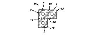
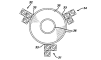
図10に示す実施形態において、本発明は主平面基板36の外周部33に取り付けられた3個の3軸コイル・センサー34,31,32を含む。さらに、主コイル35が主平面基板36上に備えられている。この主コイルは図1乃至図4の実施形態において説明した基準フィールド・トランスデューサ100と同様に使用できる。好ましくは、3軸センサーを担持している各基板および平面基板36は1個の単一の基板として形成されており、適当な折線が各基板および当該各基板が主平面基板36の外周部に取り付けられている端部に設けられていて、各校正コイルを折ることにより、それらが互いにx,yおよびz軸に沿って直交して配置できるようになっている。好ましくは、各3軸センサーは主コイル35の周りに約120°ずつ互いに離間して配置されている。
【0051】
主コイル35は約800巻き乃至1600巻き、好ましくは1550巻きの27ゲージ・ワイヤ以下の線で3インチ以下、好ましくは2.32インチの直径のコイルを形成することにより製造されているのが好ましい。また、各3軸コイル・センサー34,31,32の各校正コイルは約1400巻き乃至2200巻き、好ましくは2000巻きの46ゲージ・ワイヤで0.5インチ以下、好ましくは0.32インチの外径のコイルを形成することにより製造されているのが好ましい。あるいは、これらのコイルは基板に各コイルを印刷する等の別の技法により形成できる。さらに、リード線(図示せず)がこれらのコイルをドライバおよび増幅器のような適当な電子機器に接続するために備えられる。各リード線は外部ワイヤ、すなわち、各基板の表面上に印刷された導体の基板内の導体を構成できる。
【0052】
主コイル35および当該主コイルにおける同一面上に取り付けた校正コイル34,31,32を備えている図10の基準トランスデューサ組立体10は図1乃至図4に示す実施形態の基準トランスデューサ組立体50の全体と置き換えることができる。
【0053】
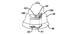
本発明のさらに別の実施形態を図11に示しており、この実施形態は主コイルの部分の部分図であって、主コイルを担持する基板の一部分上の3軸コイルの配置を示している。すなわち、この実施形態においては、3軸コイル組立体40は図8aおよび図8bに示す3軸コイル・センサー組立体から成る組立体に類似した様式で組み立てられている。しかしながら、この場合に、この3軸コイル組立体は主平面基板46上に形成した凹部41および42の中に挿入されるように構成されている。凹部41はコイル150および151の僅かに突出する部分を許容するように構成されており、凹部42はコイル152の外側への突出部を許容するように形成されている。この場合も、主コイル45が凹部42および41が形成されている同一基板、すなわち、基板46上に形成されている。
【0054】
上述のように、本発明のコイル組立体は特に上記の各実施形態において開示した個々に位置決め可能なトランスデューサ組立体と共に使用するように構成されている。例えば、図8bおよび図9bのコイル・センサー組立体は校正フィールド・トランスデューサ316として使用でき、図1乃至図4の校正トランスデューサ・ソケット314の中に配置できる。
【0055】
上記およびその他の特徴または形態の変形および組合せが本発明から逸脱することなく利用可能であり、上記の好ましい実施形態の説明は特許請求の範囲に定める本発明の範囲を意味するものではなく、本発明を例示して説明するためのものと理解するべきである。
【図面の簡単な説明】
【図1】 本発明の好ましい一実施形態の斜視図であって、患者の身体に取り付けた基準フィールド・トランスデューサを示している図である。
【図2】 本発明の一実施形態によるトランスデューサ組立体を示す概略的断面図である。
【図3】 図1において使用されている組立体の1個の要素を示す概略的斜視図である。
【図4】 図1乃至図3に示される構成要素の概略図である。
【図5】 本発明の一実施形態による基準フィールド・トランスデューサおよび校正トランスデューサの組立体の分解斜視図である。
【図6】 基準フィールド・トランスデューサが独立して移動可能である本発明の別の好ましい実施形態の側面の斜視図である。
【図7】 基準フィールド・トランスデューサが柔軟なシート状の支持体の上で独立して移動可能である本発明の別の好ましい実施形態の前面図である。
【図8a】 本発明の3個のコイル・センサーのレイアウトおよび斜視図である。
【図8b】 本発明の3個のコイル・センサーのレイアウトおよび斜視図である。
【図9a】 3個のコイル・センサーの別の実施形態のレイアウトおよび斜視図である。
【図9b】 3個のコイル・センサーの別の実施形態のレイアウトおよび斜視図である。
【図10】 互いに対して一定の配列構成を有する本発明の3個のコイル・センサーの平面図である。
【図11】 パッド上に標した3個のコイル・センサーの部分破断図である。
【符号の説明】
10 基板
12,14,16 校正コイル
13,15,17 サブパネル
18,17 折線
20 基板
21,23,25 校正コイル
22,24,26 サブパネル
27,28 折線
30 プローブ・フィールド・トランスデューサ
50 基準トランスデューサ組立体
80 フィールド送受信装置
100 コイルまたは基準フィールド・トランスデューサ[0001]
【Technical field】
The present invention relates to medical diagnostic and therapeutic systems, and more particularly to the use of a medical probe using a reference field transducer and a probe field transducer to detect position, orientation, or both within a patient's body.
[0002]
[Background]
There are many medical methods for introducing a probe, such as a catheter, into a subject or patient. In procedures such as cardiac catheterization and neurosurgery, doctors and surgeons often need to know the position of the probe tip within the body. Image processing methods such as fluoroscopy and ultrasound may be used for this purpose, but these methods are not always practical or desirable. For example, these systems typically require continuous image processing of the probe and patient during processing. In addition, fluoroscopy systems are often undesirable for exposing patients and physicians to substantial ionizing radiation.
[0003]
Many positioning systems have been proposed for detecting the position of the tip of a probe or catheter within a patient's body without requiring continuous patient image processing. For example, these systems are described in US Pat. Nos. 5,558,091, 5,391,199, 5,443,489, and published patent application WO 94, which are incorporated herein by reference. / 04938 and WO 96/05768. Other electromagnetic tracking systems not necessarily for medical use are also disclosed in U.S. Pat. Nos. 3,644,825, 3,868,565, 4,017,858, 4,054,881 and No. 4,849,692.
[0004]
The above-mentioned US Pat. Nos. 5,558,091, 5,391,199 and 5,443,489, and published patent application WO 94/04938 are Hall effect devices, magnetic The position of the probe (ie, position, orientation, or both) is determined using one or more field transducers such as a resistance device, a coil carrying the probe or another antenna. These transducers are generally located at or near the probe tip, or at precisely known locations relative to the probe tip. Such a system further utilizes one or more reference field transducers located outside the body to obtain a reference outer frame. These reference field transducers operate to transmit and detect non-ionizable fields or field components such as magnetic fields, electromagnetic radiation or acoustic energy such as ultrasonic vibrations. By transmitting a field between the external reference field transducer and the probe field transducer, the field transmission characteristics between these devices can be determined, and the position of the probe in the reference external frame and Can be used to determine orientation.
[0005]
For example, as described in US Pat. No. 5,558,091, the reference frame of the external field transducer is magnetic resonance imaging data, computerized axial tomography (“CAT”) data, Or it can be aligned with a reference frame of image data, such as conventional X-ray image processing data, so that position and / or orientation data obtained from this system can be displayed as a representation of the probe superimposed on an image of the patient's body. . The doctor can use this information to guide the probe to a desired location within the patient's body to monitor the position and orientation of the probe during treatment and measurement of its anatomy. Such an arrangement greatly enhances the physician's ability to steer the tip of the probe in the body structure and has advantages over conventional methods of manipulating the probe in the body only by touch. This system does not need to obtain an optical image of the surrounding tissue for steering purposes and can therefore be used with a probe that is too small to accommodate the optical element. In addition, these transducer-based systems can avoid the difficulties associated with probe manipulation during processing and ongoing imaging of the patient, such as the inherent ionizing radiation in fluoroscopic systems. Avoid prolonged exposure to
[0006]
Such systems typically use reference field transducers or coils that are either mounted in a fixed, immovable array in a place such as the operating room ceiling, or for surgical or catheterization. Fixed to the table. In medical applications where this system is used to track the location of a probe within a patient's body, it may happen that the above-described coil attachment interferes with the physician's free access to the patient.
[0007]
For example, the above-mentioned Patent Application Publication No. WO 94/04938 describes a catheter system that uses a plurality of non-concentric coils near the tip of the catheter. These coils generate signals in response to an externally supplied magnetic field, which allows the calculation of six different position and orientation coordinates, and placement of the catheter without the need for simultaneous image processing. Can know. Preferably, at least three such coils or radiators are arranged at a fixed location outside the body near the body region into which the catheter is introduced. For example, in cardiac catheterization, the patient is typically in a dorsal state during this procedure, and three radiators are generally fixedly arranged in a triangular arrangement in the same plane fixed below the patient's chest. The center of each coil is about 2 cm to 40 cm apart. Also, when determining the position and orientation of a catheter or probe inserted into the brain, it is desirable to place the transducer or field radiation coil near the patient's head. However, in neurosurgery, a patient may sit, stand upright, or face down. Therefore, the triangular frame holding the three radiators as described above cannot be stably disposed under the head with good usability. However, placing this frame above or to the side of the head generally interferes with the operation of the surgeon's probes and surgical instruments.
[0008]
Therefore, by adjusting and optimizing the placement of the reference field transducer, the probe tracking system and other systems related to supplying an electromagnetic field or other non-ionizable energy field to the human body. It is desirable to increase accuracy and effectiveness. Such a flexible placement of transducers allows each transducer to be moved to the best possible position that increases the sensitivity of the positioning system, allowing for placement of the transducer adapted to the individual case.
[0009]
DISCLOSURE OF THE INVENTION
One example aspect of the present invention provides a system for determining the placement of a probe within a patient. The system according to this aspect of the present invention preferably comprises a probe having one or more probe field transducers attached thereto. In addition, one or more reference field transducers are provided. The term “field transducer” as used in this disclosure includes devices capable of transmitting a non-ionizable field such as a magnetic field, an electromagnetic field, an acoustic or an optical field, and such a field. And a device capable of detecting one or more of the components. In the system according to this aspect of the invention, the reference field transducers can be moved independently of each other and can be adapted to the individual case, selected by the user, desired for the patient's body. Can be positioned. Most preferably, the system comprises means for mounting the reference field transducer on the patient's body. In a particularly preferred arrangement, these reference field transducers are not in mechanical contact with each other, and each reference field transducer is desired by the user without being mechanically constrained by the placement of other reference field transducers. Can be placed at any position. In addition, calibration means are provided, such as for example when the reference field transducer is mounted on the patient's body while the reference field transducer is placed in the desired position. Determine the relative placement of the field transducers relative to each other. The term “disposition” as used in this disclosure for a single object refers to the position of the object, the orientation of the object, or both. Also, the term “relative disposition” used in this disclosure for any two objects refers to the direction from one object to another object, from one object to another object. Means the distance to an object, or both, and includes the orientation of other objects within the frame of reference for each object. Most preferably, the calibration means is arranged to completely determine all parameters of the relative placement of each field transducer relative to each other, and the distance and direction from each field transducer to each other field transducer. The orientation of all field transducers is fully known.
[0010]
The system further drives one or more non-existing probe field transducers that drive the reference field transducer and the probe field transducer to detect each field transmitted with the reference field transducer. A transmission means for transmitting the ionizable field is provided. For example, when the transmission means drives a reference field transducer to transmit a magnetic or electromagnetic field, the probe field transducer detects a field characteristic received at one or more probe field transducers. Furthermore, calculation means are provided for determining the placement of the probe in the reference frame of the reference field transducer. This calculation is based on the detected field characteristics and the relative placement of the reference field transducers relative to each other.
[0011]
Since the above reference field transducers can be placed independently on or near the patient's body, they can be placed in an optimal arrangement and within a specific area of interest where the probe must be placed during a particular process. Better sensitivity and signal-to-noise ratio. In addition, the reference field transducer positioning described above can be selected so as not to interfere with access for surgical or other medical procedures. As will be described further below, the reference frame defined by the reference field transducer can be matched to the reference frame of the already obtained image, and the probe representation can be displayed superimposed on this already obtained image. In a preferred embodiment where reference field transducers are mounted on the patient's body, the frame of reference defined by these reference field transducers moves with the patient. Therefore, alignment with the already obtained images can be maintained without adjustment or realignment regardless of patient movement. In a system according to another embodiment of the present invention, the calibration means and calculation means described above periodically re-determine the relative placement of the reference field transducer and the probe placement relative to the re-determined reference field transducer. The arrangement is such that redetermination is made based on the arrangement. For example, the system operates periodically and each period includes a re-determination process for the relative placement of the reference field transducers and a determination process for the probe placement. In other words, the reference frame of the reference field transducer is updated before each measurement process of the probe placement. Alternatively, the placement of the reference field transducer can be updated periodically. These systems allow a reference field transducer to be mounted on a movable element in the body, such as on the surface of the abdomen or thorax.
[0012]
The calibration means may comprise one or more calibration field transducers attached to one or more reference field transducers. This provides one or more reference field transducers in a reference assembly with one or more calibration field transducers. The calibration means detects, for example, a non-ionizable field transmitted to or from each calibration field transducer as a field transmitted from a reference transducer of another reference assembly. Arranged to determine the relative placement of the reference field transducer.
[0013]
Another aspect of the invention provides a method for determining the placement of a probe within a patient. Desirably, the method according to this aspect of the invention comprises a probe as described above having one or more probe field transducers and a position corresponding to the individual patient's body needs selected by the user. And a step of positioning a plurality of reference field transducers that can be independently positioned relative to each other as required. As already described for this device, the reference field transducers are placed in their desired locations at the same time as the device placement of the reference field transducers relative to each other is determined. The probe is then positioned by transmitting one or more non-ionizable fields between the probe field transducer and the reference field transducer and detecting these fields. As a result, the relative placement of the probe with respect to the reference field transducer is determined by the detected field characteristics and the relative placement of the reference field transducers with respect to each other. As described for each of the above devices, it is desirable that the relative placement of the reference field transducers be re-determined frequently.
[0014]
Yet another aspect of the invention includes an apparatus for generating or detecting a non-ionizing field that is transmitted to or from a patient's body. A form according to this aspect of the invention comprises a plurality of reference field transducers and means for placing each reference field transducer independently of one another at a required location close to the medical patient's body. Yes. The apparatus according to this aspect of the invention can be utilized in the systems and methods described above. Such placement means may include means for securing each reference field transducer to the patient's body, such as, for example, an adhesive means or other securing device that can engage the patient's body. Yet another aspect of the invention comprises a plurality of separate reference field transducers and means such as an adhesive or other fixation device for securing the reference field transducer to the patient's body. Including equipment. Yet another aspect of the present invention includes a reference field transducer assembly containing a coil or other field transducer that generates heat during operation, and a housing structure that houses the coil. The assembly has a front portion and a rear portion that face the patient during operation. In addition, means are provided in the housing for limiting the heating of the front portion by the heat generated in the coil. For example, the housing may include a thermal insulator disposed between the coil and the front portion and may include means for dissipating heat within the housing or through the rear portion. These and other objects, features and advantages of the present invention will become more apparent from the following detailed description based on the drawings.
[0015]
The present invention relates to a magnetic field sensor used to detect the position and orientation of a medical probe within a patient's body. The sensor of the present invention is particularly suitable for use as an independently positionable reference transducer assembly. Such an assembly is, for example, a share entitled “Independently Positionable Transducers for Location System” (the '650 patent application), the disclosure of which is incorporated herein by reference. In the co-pending International Patent Application No. PCT / US97 / 02650.
[0016]
[Mode for carrying out the present invention]
The system according to one embodiment of the invention is used with an elongated probe in the form of a tube or
[0017]
The elongate probe or
[0018]
The apparatus further comprises a set of
[0019]
The
[0020]
A plurality of
[0021]
Reference field transducer or
[0022]
The field transmitter /
[0023]
When placed on the patient, the
[0024]
In FIGS. 1-4, since the
[0025]
In yet another configuration, the system can be partially omitted by changing the system to use a relatively small number of calibration transducers. Thus, in the case of the system shown in FIGS. 1-4, which shows three
[0026]
In another preferred embodiment, a fixed array of calibration field transducers is provided, such as calibration array 55 (FIG. 1) including a plurality of
[0027]
When calibration of the reference field transducer is complete, the placement of the probe within the external reference frame defined by the reference field transducer is determined, for example, as described in US Pat. No. 5,558,091. By transmitting and receiving a non-ionizable field between the probe field transducer and the probe field transducer.
[0028]
In a method according to one embodiment of the present invention, a patient is placed on a
[0029]
Next, the distal end portion of the probe 28 enters the patient's body toward the region of interest while holding the
[0030]
In certain approaches, it may be desirable to display the position of the probe on the
[0031]
One of the major advantages gained by embodiments of the present invention that attach reference field transducers directly to the patient is that they define a reference frame that is fixed relative to the patient. In many cases, such as when a reference field transducer is attached to a fixed part of the patient's body (such as the head), it is not necessary to fix the patient in any position on the patient bed. This is because there is no need to prevent relative movement between the patient and a reference frame that is typically attached to the patient bed or defined by a reference field transducer mounted on the wall or ceiling. . For example, if reference field transducers are attached to the head, even if the patient's head moves, the relative movement of the head relative to these transducers because the reference field transducer is located on the head Does not occur. In other words, the reference frame defined by the
[0032]
If the reference transducers are not fixed relative to each other, such as when the reference transducers are attached to a flexible or movable part of the patient's anatomy, the system will position the reference assemblies relative to each other. Need to be recalibrated. Such a recalibration process is performed by repeating the calibration process described above, including the operation of the calibration transducer and the calculation of the relative placement of the reference assembly. This recalibration process can be performed periodically, for example, every few seconds during operation. More preferably, the recalibration process is performed each time the position of the probe 28 is determined. Thus, this system can operate periodically. Each period is a calibration phase in which the relative placement of the reference assembly and field transducer is set, and the position and / or orientation of the probe 28 is determined within the reference frame of the reference assembly and
[0033]
In the above embodiment, the various transducers are time-multiplexed communication systems. For example, various reference field transducers operate at different times during each calibration period. Also, other multiplex communication schemes such as frequency division and code division multiplex communication schemes can be used. Further, in the above configuration, all reference field transducers are configured to emit a magnetic field and the calibration field transducer and the probe field transducer are configured to detect these fields. The reverse configuration is also possible, i.e., the probe and calibration field transducer are transmitters and the reference field transducer is a detector. In yet another possible configuration, the calibration field transducer comprises several transmitters and several detectors, and the relative placement of the
[0034]
In yet another configuration, a probe field transducer or another movable field transducer is used in place of the calibration transducer. During the above calibration process, the movable field transducer is sequentially inserted into the various
[0035]
As shown in FIG. 5, the reference transducer assembly includes a coil or
[0036]
In the above embodiment, each reference transducer is attached to the patient. However, an independently positionable reference transducer may be mounted at another location near the patient. In FIG. 6, another embodiment of the present invention is shown, in which the reference field transducers are attached to a common structure but are still movable independently of each other. In this case, a
[0037]
Yet another embodiment of the present invention is shown in FIG. 7, in which a single sheet-
[0038]
The coil or transducer arrangement of the present invention eliminates many of the problems associated with fixed, non-movable coil systems. For example, a non-moving coil system can interfere with surgeon access. Also, the non-moving coil system cannot be placed above the patient in general to block light, and cannot be placed below the patient if the metal can cause interference. The bed cannot be replaced or repositioned. Furthermore, in the case of a non-movable coil, the highly accurate mapping volume that is useful when the coil cannot move at each moment is very small.
[0039]
The present invention eliminates the above problems because the reference field transducer can be placed in a least disturbing manner and can be moved from a (close) path to a new location during processing. Furthermore, the transducer (according to the invention) can be moved closer to the area of interest, so that better field concentration and better reading processing can be performed. Furthermore, the present invention allows the use of relatively small reference transducers since it is not necessary to have a large coil to generate the field over a large area to ensure a wide convergence of the field. In a preferred embodiment, the transducers described above are disposable so that replacement of damaged or contaminated transducers is easy and the use of different sizes or types of transducers for different applications is possible. Such a set of reference field transducers can be provided by a physician with or without a calibration field transducer, which may include the same transducer or different sized transducers for different applications.
[0040]
The present invention can be used with the system disclosed in US patent application Ser. No. 08 / 476,380, which is incorporated herein by reference. In this US patent application Ser. No. 08 / 476,380, a sensor on a probe is supplied to a reference field transducer or coil to ensure that a field of a predetermined range is received regardless of the position of the probe. A feedback mechanism is used to regulate the current. This ensures that the sensor operates within its optimum range and allows the use of compact transmitters and sensors. Accordingly, the non-ionizable field strength generated by the reference field transducer and / or probe field transducer using the feedback technique disclosed in the above-mentioned US patent application Ser. No. 08 / 476,380 in conjunction with the present invention. Can be adjusted.
[0041]
Further, the present invention relates to US Provisional Patent Application No. 60 / 012,275 filed on Feb. 26, 1996, No. 60 / 011,721 filed Feb. 15, 1996, and 1996. No. 60 / 031,824, filed Nov. 26, and commonly assigned to the assignee of the present application, “Medical Procedures And Apparatus Using Intrabody Probes” It can be used with the multiple probe system disclosed in the PCT patent application filed on the same day as this application entitled “Using Intrabody Probes”. Each of the above provisional patent applications is also included in the present specification as a reference. In a preferred embodiment of the system (according to the invention), a medical probe, such as a catheter, is applied to or from the field transducer attached to both the probe and another probe, respectively. Is guided in the patient's body by determining the relative placement of the probe with respect to another probe. In particular, a site probe can be fixed to an affected part in the body, and an instrument probe for treating the affected part can be guided to the affected part by monitoring the relative arrangement of these probes. In many embodiments of the above system (according to the invention), it is not necessary to match the position of the probe to the image data or to superimpose the position of the probe on the image. Accordingly, the independently movable reference field transducer configuration of the present invention can be used with the site probe / instrument probe system described above, with or without simultaneous patient imaging, to be defined by the reference field transducer. The placement of each probe within a given reference frame can be determined. As long as both these probe placements are detected within the same reference frame, the relative placement of these two probes can be determined. For example, even if the reference field transducers move relative to each other (such as when the field transducers are mounted on soft tissue), the system is recalibrated during each cycle or at any time during which movement occurs. If the placement of the field transducers relative to each other is updated, the relative placement can be properly determined. In yet another variation, the system described above when the reference field transducer is attached to a body part, such as a region such as the chest, that repeatedly moves with the breathing cycle and is susceptible to repeated natural movements. Can be calibrated at a specific time in the natural travel cycle (eg, end of expiration or end of inspiration) and can be operated to determine the position of the probe at the same time in the natural travel cycle. Furthermore, such a system requires superimposition of probe representations on the already obtained image, for example, when the image is an image obtained at the same time in the natural movement cycle as described above. Can also be used.
[0042]
Also, excellent signal-to-noise ratio characteristics can be achieved with the independently placeable reference field transducer of the present invention. In general, by using one or more reference field transducers in a probe positioning system, there is a constant volume region (so-called “optimal region”) associated with a field transducer with an optimized signal-to-noise ratio of the assembly. In this region, high-precision field measurement can be performed by the probe transducer. On the other hand, in the case of a conventional probe positioning system where the reference transducer is mounted in a fixed position around the patient bed, this optimal area typically covers a wide area over all possible areas of involvement. For example, a system that uses a transducer attached to a bed may be required to position a probe in a patient's chest and in another patient's head. However, the wider the optimal region, the more difficult it is to maintain a high signal-to-noise ratio throughout such region. However, with the independently deployable transducer assembly of the present invention, this optimum area is smaller and more highly concentrated. Further, in each process, the optimum region can be formed so as to coincide with the region for tracking the probe. Accordingly, preferred embodiments of the present invention can provide superior signal-to-noise ratio characteristics compared to fixed transducer assemblies that use the same transducer in a large fixed array. The signal-to-noise ratio characteristics of this system also depend on the characteristics of the probe transducer. Thus, the superior characteristics provided by the preferred embodiment of the present invention can provide acceptable signal-to-noise ratio characteristics even in the case of probe transducers and less sensitive probe transducers that can be miniaturized.
[0043]
Alternatively, the advantage provided by the movable transducer assembly described above is that it allows the use of a relatively small, inexpensive and unobtrusive reference transducer while maintaining sufficient characteristics. In addition, such a reference field transducer can be arranged to provide optimal characteristics within the above region without interfering with the physician's access to the patient. For example, if the surgeon operates on the left side of the head by craniotomy, the above reference assembly can be placed behind, above and on the right side of the head.
[0044]
Yet another advantage of the embodiments disclosed herein is that if the reference field transducer is moved or if the reading in the initial placement of the reference field transducer is insufficient, the reference field The ability to adjust the transducer. This allows the surgeon to reposition the reference assembly during processing or increase the additional reference assembly.
[0045]
While aspects of the preferred embodiment described above have been described with respect to a system for position determination based on a magnetic field, the present invention emits and detects electromagnetic, magnetic, acoustic, optical, ultrasonic or other non-ionizable fields. It will be understood that it is equally applicable to other types of position determination systems known in the art, such as systems that use other forms of field transducers, including those.
[0046]
The method of using calibration field transducers to calibrate the relative positions of the reference transducers relative to each other according to the present invention is also used to replace or increase the manner in which the relative positions of the associated reference field transducers are determined. it can. That is, instead of providing a rotary measuring device such as an optical encoder device that can accurately determine the angle between the transducer carrying arms and make the relative position of the reference field transducer known, the calibration field Transducers can be used as disclosed herein.
[0047]
The coil sensor according to the present invention is particularly suitable for use as a calibration field transducer and is shown in FIGS. 1-4, but the present invention can also be used in other applications where measurement of magnetic field components is desired. . In FIG. 8a of the present application, in the case of an example of a preferred embodiment of the present invention, a three-axis coil sensor is equipped with three separate calibration coils 12, 14, and 16 on a single
[0048]
When forming the sensor of the present invention, the
[0049]
In another embodiment of the invention as shown in FIG. 122,124 and 126 is
[0050]
In the embodiment shown in FIG. 10, the present invention relates to three three-axis coil sensors attached to the outer
[0051]
The
[0052]
[0053]
Yet another embodiment of the present invention is shown in FIG. 11, which is a partial view of a portion of a main coil, showing the arrangement of a triaxial coil on a portion of a substrate carrying the main coil. . That is, in this embodiment, the
[0054]
As mentioned above, the coil assembly of the present invention is specifically configured for use with the individually positionable transducer assemblies disclosed in the above embodiments. For example, the coil sensor assembly of FIGS. 8b and 9b can be used as a
[0055]
Variations and combinations of the above and other features or forms may be used without departing from the invention, and the above description of preferred embodiments does not imply the scope of the invention as defined in the claims, It should be understood that the invention is illustrative and described.
[Brief description of the drawings]
FIG. 1 is a perspective view of a preferred embodiment of the present invention showing a reference field transducer attached to a patient's body.
FIG. 2 is a schematic cross-sectional view illustrating a transducer assembly according to an embodiment of the present invention.
FIG. 3 is a schematic perspective view showing one element of the assembly used in FIG. 1;
4 is a schematic diagram of the components shown in FIGS. 1-3. FIG.
FIG. 5 is an exploded perspective view of a reference field transducer and calibration transducer assembly according to one embodiment of the invention.
FIG. 6 is a side perspective view of another preferred embodiment of the present invention in which the reference field transducer is independently movable.
FIG. 7 is a front view of another preferred embodiment of the present invention in which the reference field transducer is independently movable on a flexible sheet-like support.
FIG. 8a is a layout and perspective view of three coil sensors of the present invention.
FIG. 8b is a layout and perspective view of three coil sensors of the present invention.
FIG. 9a is a layout and perspective view of another embodiment of a three coil sensor.
FIG. 9b is a layout and perspective view of another embodiment of a three coil sensor.
FIG. 10 is a plan view of three coil sensors of the present invention having a fixed arrangement with respect to each other.
FIG. 11 is a partially cutaway view of three coil sensors marked on a pad.
[Explanation of symbols]
10 Substrate
12, 14, 16 Calibration coil
13, 15, 17 Subpanel
18, 17 broken line
20 substrates
21,23,25 Calibration coil
22, 24, 26 Subpanel
27, 28 broken line
30 Probe Field Transducer
50 Reference transducer assembly
80 field transceiver
100 coil or reference field transducer
Claims (9)
(a)外周端部を有する主平面状基板に設けた主コイルと、(A) a main coil provided on a main planar substrate having an outer peripheral end;
(b)1個以上の3軸磁場感知素子と、を備え、当該素子がそれぞれ、(B) one or more three-axis magnetic field sensing elements, each of the elements,
(i)少なくとも3個の素子担持サブパネルを有する概ね平面状の基板であって、当該サブパネルが前記基板において1個以上の折線により互いに分離している基板と、(I) a generally planar substrate having at least three element carrying subpanels, wherein the subpanels are separated from each other by one or more fold lines in the substrate;
(ii)前記素子担持サブパネルの各1個の上にそれぞれ配置されている3個の校正素子と、を備え、(Ii) three calibration elements respectively disposed on each one of the element carrying sub-panels,
前記折線において前記サブパネルの少なくとも2個を折ることにより、前記各校正素子が前記3軸センサーの設定時に3個の相互に直交する軸に沿って配置可能であり、By folding at least two of the sub-panels at the fold line, the calibration elements can be arranged along three mutually orthogonal axes when setting the three-axis sensor,
前記主平面状基板および前記基板が単一の基板により形成されていることを特徴とする、折り畳み可能な基準フィールド・トランスデューサ組立体。A foldable reference field transducer assembly characterized in that the main planar substrate and the substrate are formed by a single substrate.
(c)1個以上のプローブ・フィールド・トランスデューサを取り付けたプローブと、(C) a probe with one or more probe field transducers attached thereto;
(d)互いに対して独立して移動可能であって、患者の身体に対して所望の個別に適応可能な位置に配置可能な複数の基準フィールド・トランスデューサと、(D) a plurality of reference field transducers that are movable independently of each other and that can be placed in desired individually adaptable positions relative to the patient's body;
(e)前記基準フィールド・トランスデューサがそれぞれの所望の位置に配置されている間に、当該フィールド・トランスデューサの互いに対する相対的な配置を決定するための校正手段と、(E) calibration means for determining the relative placement of the field transducers relative to each other while the reference field transducers are placed at their desired positions;
(f)前記基準フィールド・トランスデューサおよび前記1個以上のプローブ・フィールド・トランスデューサを作動して1種類以上の非イオン化性の場を送信させると共に当該送信された場を検出させることにより、当該各場が基準フィールド・トランスデューサとプローブ・フィールド・トランスデューサとにより構成される各送信機−受信機の対における1個の構成要素により送信されると共にこの対における他の構成要素により検出されるようにするための送信手段と、(F) actuating the reference field transducer and the one or more probe field transducers to transmit one or more non-ionizable fields and to detect the transmitted fields; To be transmitted by one component in each transmitter-receiver pair consisting of a reference field transducer and a probe field transducer and detected by the other components in this pair Means for sending
(g)前記検出された各場の特性と前記基準フィールド・トランスデューサの互いに対する相対的な配置とにより当該基準フィールド・トランスデューサに対するプローブの相対的な配置を決定するための計算手段と、を備え、(G) calculating means for determining the relative placement of the probe relative to the reference field transducer by means of the detected field characteristics and the relative placement of the reference field transducer with respect to each other;
前記基準フィールド・トランスデューサがそれぞれ請求項1に記載の基準フィールド・トランスデューサである、前記システム。The system of claim 1, wherein each of the reference field transducers is a reference field transducer according to claim 1.
(h)請求項1に記載の複数の基準フィールド・トランスデューサと、(H) a plurality of reference field transducers according to claim 1;
(i)前記各基準フィールド・トランスデューサを、患者の身体に近接した所望の個別に適応可能な位置に互いに対して独立して配置する手段と、を備える前記装置。(I) means for independently positioning each reference field transducer relative to each other at a desired individually adaptable position proximate to the patient's body.
当該各基準組立体が、非イオン化性の場を発生または検出するための請求項1に記載の基準フィールド・トランスデューサと、医療患者の身体に基準トランスデューサ組立体を、他の基準トランスデューサ組立体とは独立して取り付ける手段と、を備える前記キット。The reference field transducer of claim 1 for generating or detecting a non-ionizable field, each reference assembly, a reference transducer assembly in a medical patient's body, and other reference transducer assemblies. Means for independently mounting.
一定の構造体と、A certain structure,
当該構造体に取り付けられて非イオン化性の場を発生または検出するための請求項1にClaim 1 for generating or detecting a non-ionizable field attached to the structure. 記載の基準フィールド・トランスデューサと、A reference field transducer as described;
前記構造体に対して所定の配置で非イオン化性の場を発生または検出するように構成された1個以上の校正フィールド・トランスデューサを保持するための手段と、Means for holding one or more calibration field transducers configured to generate or detect a non-ionizable field in a predetermined arrangement relative to the structure;
前記構造体を患者の身体に固定するための手段と、を備える前記基準トランスデューサ組立体。Means for securing the structure to a patient's body.
一定の構造体と、A certain structure,
当該構造体に取り付けられて非イオン化性の場を発生または検出するための請求項1に記載の基準フィールド・トランスデューサと、The reference field transducer of claim 1 for generating or detecting a non-ionizable field attached to the structure;
前記構造体を患者の身体に固定するための手段と、Means for securing the structure to a patient's body;
前記基準フィールド・トランスデューサにおいて発生する熱による患者の加熱を制限するための手段と、を備える前記基準トランスデューサ組立体。Means for limiting patient heating by heat generated in the reference field transducer.
Applications Claiming Priority (3)
| Application Number | Priority Date | Filing Date | Title |
|---|---|---|---|
| US7985898P | 1998-03-30 | 1998-03-30 | |
| US60/079,858 | 1998-03-30 | ||
| PCT/US1999/006256 WO1999049783A1 (en) | 1998-03-30 | 1999-03-22 | Three-axis coil sensor |
Publications (3)
| Publication Number | Publication Date |
|---|---|
| JP2002509749A JP2002509749A (en) | 2002-04-02 |
| JP2002509749A5 JP2002509749A5 (en) | 2006-05-18 |
| JP4156195B2 true JP4156195B2 (en) | 2008-09-24 |
Family
ID=22153250
Family Applications (1)
| Application Number | Title | Priority Date | Filing Date |
|---|---|---|---|
| JP2000540755A Expired - Lifetime JP4156195B2 (en) | 1998-03-30 | 1999-03-22 | 3-axis coil sensor |
Country Status (9)
| Country | Link |
|---|---|
| US (1) | US6161032A (en) |
| EP (1) | EP1067863B1 (en) |
| JP (1) | JP4156195B2 (en) |
| AU (1) | AU3197699A (en) |
| CA (1) | CA2325540C (en) |
| DE (1) | DE69928783T2 (en) |
| ES (1) | ES2253882T3 (en) |
| IL (1) | IL138369A (en) |
| WO (1) | WO1999049783A1 (en) |
Families Citing this family (207)
| Publication number | Priority date | Publication date | Assignee | Title |
|---|---|---|---|---|
| FR2652928B1 (en) | 1989-10-05 | 1994-07-29 | Diadix Sa | INTERACTIVE LOCAL INTERVENTION SYSTEM WITHIN A AREA OF A NON-HOMOGENEOUS STRUCTURE. |
| ES2115776T3 (en) | 1992-08-14 | 1998-07-01 | British Telecomm | POSITION LOCATION SYSTEM. |
| US5803089A (en) | 1994-09-15 | 1998-09-08 | Visualization Technology, Inc. | Position tracking and imaging system for use in medical applications |
| US6226548B1 (en) | 1997-09-24 | 2001-05-01 | Surgical Navigation Technologies, Inc. | Percutaneous registration apparatus and method for use in computer-assisted surgical navigation |
| US6021343A (en) | 1997-11-20 | 2000-02-01 | Surgical Navigation Technologies | Image guided awl/tap/screwdriver |
| US6348058B1 (en) | 1997-12-12 | 2002-02-19 | Surgical Navigation Technologies, Inc. | Image guided spinal surgery guide, system, and method for use thereof |
| US20030036746A1 (en) | 2001-08-16 | 2003-02-20 | Avi Penner | Devices for intrabody delivery of molecules and systems and methods utilizing same |
| US6477400B1 (en) | 1998-08-20 | 2002-11-05 | Sofamor Danek Holdings, Inc. | Fluoroscopic image guided orthopaedic surgery system with intraoperative registration |
| AU2388100A (en) | 1998-12-23 | 2000-07-12 | Peter D Jakab | Magnetic resonance scanner with electromagnetic position and orientation tracking device |
| US7549960B2 (en) * | 1999-03-11 | 2009-06-23 | Biosense, Inc. | Implantable and insertable passive tags |
| US7590441B2 (en) | 1999-03-11 | 2009-09-15 | Biosense, Inc. | Invasive medical device with position sensing and display |
| US7558616B2 (en) * | 1999-03-11 | 2009-07-07 | Biosense, Inc. | Guidance of invasive medical procedures using implantable tags |
| US7575550B1 (en) | 1999-03-11 | 2009-08-18 | Biosense, Inc. | Position sensing based on ultrasound emission |
| US7174201B2 (en) * | 1999-03-11 | 2007-02-06 | Biosense, Inc. | Position sensing system with integral location pad and position display |
| US6470207B1 (en) | 1999-03-23 | 2002-10-22 | Surgical Navigation Technologies, Inc. | Navigational guidance via computer-assisted fluoroscopic imaging |
| US6491699B1 (en) | 1999-04-20 | 2002-12-10 | Surgical Navigation Technologies, Inc. | Instrument guidance method and system for image guided surgery |
| US9572519B2 (en) | 1999-05-18 | 2017-02-21 | Mediguide Ltd. | Method and apparatus for invasive device tracking using organ timing signal generated from MPS sensors |
| US7126450B2 (en) | 1999-06-21 | 2006-10-24 | Access Business Group International Llc | Inductively powered apparatus |
| US6825620B2 (en) | 1999-06-21 | 2004-11-30 | Access Business Group International Llc | Inductively coupled ballast circuit |
| US6626899B2 (en) | 1999-06-25 | 2003-09-30 | Nidus Medical, Llc | Apparatus and methods for treating tissue |
| US6747539B1 (en) | 1999-10-28 | 2004-06-08 | Michael A. Martinelli | Patient-shielding and coil system |
| US6474341B1 (en) | 1999-10-28 | 2002-11-05 | Surgical Navigation Technologies, Inc. | Surgical communication and power system |
| US6493573B1 (en) * | 1999-10-28 | 2002-12-10 | Winchester Development Associates | Method and system for navigating a catheter probe in the presence of field-influencing objects |
| AU1240801A (en) | 1999-10-28 | 2001-05-08 | Enterprise Medical Technology, Inc. | Coil structures and methods for generating magnetic fields |
| US6499488B1 (en) | 1999-10-28 | 2002-12-31 | Winchester Development Associates | Surgical sensor |
| US11331150B2 (en) | 1999-10-28 | 2022-05-17 | Medtronic Navigation, Inc. | Method and apparatus for surgical navigation |
| US7366562B2 (en) | 2003-10-17 | 2008-04-29 | Medtronic Navigation, Inc. | Method and apparatus for surgical navigation |
| US8239001B2 (en) | 2003-10-17 | 2012-08-07 | Medtronic Navigation, Inc. | Method and apparatus for surgical navigation |
| US8644907B2 (en) | 1999-10-28 | 2014-02-04 | Medtronic Navigaton, Inc. | Method and apparatus for surgical navigation |
| US6381485B1 (en) | 1999-10-28 | 2002-04-30 | Surgical Navigation Technologies, Inc. | Registration of human anatomy integrated for electromagnetic localization |
| US6725080B2 (en) | 2000-03-01 | 2004-04-20 | Surgical Navigation Technologies, Inc. | Multiple cannula image guided tool for image guided procedures |
| US6535756B1 (en) | 2000-04-07 | 2003-03-18 | Surgical Navigation Technologies, Inc. | Trajectory storage apparatus and method for surgical navigation system |
| US7085400B1 (en) | 2000-06-14 | 2006-08-01 | Surgical Navigation Technologies, Inc. | System and method for image based sensor calibration |
| US7809421B1 (en) * | 2000-07-20 | 2010-10-05 | Biosense, Inc. | Medical system calibration with static metal compensation |
| US6564158B1 (en) * | 2000-08-17 | 2003-05-13 | Holaday Industries, Inc. | Broadband electromagnetic field component measurement system |
| US20040087877A1 (en) | 2000-08-23 | 2004-05-06 | Besz William John | Catheter locator apparatus and method of use |
| US6820614B2 (en) * | 2000-12-02 | 2004-11-23 | The Bonutti 2003 Trust -A | Tracheal intubination |
| US7210223B2 (en) * | 2000-12-13 | 2007-05-01 | Image-Guided Neurologics, Inc. | Method of manufacturing a microcoil construction |
| US6792303B2 (en) * | 2001-05-11 | 2004-09-14 | Scimed Life Systems, Inc. | Apparatus for improved sensor accuracy |
| US6636757B1 (en) | 2001-06-04 | 2003-10-21 | Surgical Navigation Technologies, Inc. | Method and apparatus for electromagnetic navigation of a surgical probe near a metal object |
| US7383073B1 (en) * | 2001-10-16 | 2008-06-03 | Z-Kat Inc. | Digital minimally invasive surgery system |
| US6947786B2 (en) | 2002-02-28 | 2005-09-20 | Surgical Navigation Technologies, Inc. | Method and apparatus for perspective inversion |
| US8996169B2 (en) | 2011-12-29 | 2015-03-31 | Mako Surgical Corp. | Neural monitor-based dynamic haptics |
| US11202676B2 (en) | 2002-03-06 | 2021-12-21 | Mako Surgical Corp. | Neural monitor-based dynamic haptics |
| US8010180B2 (en) | 2002-03-06 | 2011-08-30 | Mako Surgical Corp. | Haptic guidance system and method |
| US8095200B2 (en) | 2002-03-06 | 2012-01-10 | Mako Surgical Corp. | System and method for using a haptic device as an input device |
| US6990368B2 (en) | 2002-04-04 | 2006-01-24 | Surgical Navigation Technologies, Inc. | Method and apparatus for virtual digital subtraction angiography |
| US7998062B2 (en) | 2004-03-29 | 2011-08-16 | Superdimension, Ltd. | Endoscope structures and techniques for navigating to a target in branched structure |
| AU2003257321A1 (en) * | 2002-08-16 | 2004-03-03 | Orthosoft Inc. | Interface apparatus for passive tracking systems and method of use thereof |
| US20040068178A1 (en) * | 2002-09-17 | 2004-04-08 | Assaf Govari | High-gradient recursive locating system |
| EP1563315A2 (en) * | 2002-11-14 | 2005-08-17 | GE Medical Systems Global Technology Company LLC | Interchangeable localizing devices for use with tracking systems |
| US7697972B2 (en) | 2002-11-19 | 2010-04-13 | Medtronic Navigation, Inc. | Navigation system for cardiac therapies |
| US7599730B2 (en) | 2002-11-19 | 2009-10-06 | Medtronic Navigation, Inc. | Navigation system for cardiac therapies |
| US7660623B2 (en) | 2003-01-30 | 2010-02-09 | Medtronic Navigation, Inc. | Six degree of freedom alignment display for medical procedures |
| US7542791B2 (en) | 2003-01-30 | 2009-06-02 | Medtronic Navigation, Inc. | Method and apparatus for preplanning a surgical procedure |
| US7519413B1 (en) | 2003-02-20 | 2009-04-14 | S.A. Instruments, Inc. | Apparatus and method for measuring motion in a strong magnetic field |
| US7314448B2 (en) * | 2003-03-28 | 2008-01-01 | Scimed Life Systems, Inc. | Imaging transducer assembly |
| JP5798280B2 (en) * | 2003-04-22 | 2015-10-21 | コーニンクレッカ フィリップス エヌ ヴェ | Multi-scale localization method |
| AU2003902259A0 (en) * | 2003-05-13 | 2003-05-29 | Telezygology Inc. | Improved assembly system |
| US7090639B2 (en) * | 2003-05-29 | 2006-08-15 | Biosense, Inc. | Ultrasound catheter calibration system |
| US7158754B2 (en) | 2003-07-01 | 2007-01-02 | Ge Medical Systems Global Technology Company, Llc | Electromagnetic tracking system and method using a single-coil transmitter |
| JP2005052637A (en) * | 2003-07-18 | 2005-03-03 | Pentax Corp | Capsule type device and capsule type device driving control system |
| US20050027195A1 (en) * | 2003-08-01 | 2005-02-03 | Assaf Govari | Calibration data compression |
| US7313430B2 (en) * | 2003-08-28 | 2007-12-25 | Medtronic Navigation, Inc. | Method and apparatus for performing stereotactic surgery |
| GB0320787D0 (en) * | 2003-09-05 | 2003-10-08 | Depuy Int Ltd | Flexible image guided surgery marker |
| EP2316328B1 (en) | 2003-09-15 | 2012-05-09 | Super Dimension Ltd. | Wrap-around holding device for use with bronchoscopes |
| EP1667749B1 (en) | 2003-09-15 | 2009-08-05 | Super Dimension Ltd. | System of accessories for use with bronchoscopes |
| US7835778B2 (en) | 2003-10-16 | 2010-11-16 | Medtronic Navigation, Inc. | Method and apparatus for surgical navigation of a multiple piece construct for implantation |
| US7840253B2 (en) | 2003-10-17 | 2010-11-23 | Medtronic Navigation, Inc. | Method and apparatus for surgical navigation |
| JP4150663B2 (en) * | 2003-12-25 | 2008-09-17 | オリンパス株式会社 | In-subject position detection system |
| US7966058B2 (en) * | 2003-12-31 | 2011-06-21 | General Electric Company | System and method for registering an image with a representation of a probe |
| US8764725B2 (en) | 2004-02-09 | 2014-07-01 | Covidien Lp | Directional anchoring mechanism, method and applications thereof |
| US7976539B2 (en) | 2004-03-05 | 2011-07-12 | Hansen Medical, Inc. | System and method for denaturing and fixing collagenous tissue |
| EP1720480A1 (en) | 2004-03-05 | 2006-11-15 | Hansen Medical, Inc. | Robotic catheter system |
| US20050209524A1 (en) * | 2004-03-10 | 2005-09-22 | General Electric Company | System and method for receiving and storing information pertaining to a patient |
| EP1731093B1 (en) * | 2004-03-29 | 2013-01-09 | Olympus Corporation | System for detecting position in examinee |
| JP4488294B2 (en) * | 2004-03-29 | 2010-06-23 | オリンパス株式会社 | In-subject position detection system |
| JP4054319B2 (en) * | 2004-03-29 | 2008-02-27 | オリンパス株式会社 | Power supply |
| US20050228251A1 (en) * | 2004-03-30 | 2005-10-13 | General Electric Company | System and method for displaying a three-dimensional image of an organ or structure inside the body |
| US20050222509A1 (en) * | 2004-04-02 | 2005-10-06 | General Electric Company | Electrophysiology system and method |
| US20050228252A1 (en) * | 2004-04-02 | 2005-10-13 | General Electric Company | Electrophysiology system and method |
| US7567834B2 (en) | 2004-05-03 | 2009-07-28 | Medtronic Navigation, Inc. | Method and apparatus for implantation between two vertebral bodies |
| US20050288727A1 (en) * | 2004-06-01 | 2005-12-29 | Abraham Penner | Wireless sensing devices for evaluating heart performance |
| US20060064142A1 (en) | 2004-09-17 | 2006-03-23 | Cardiac Pacemakers, Inc. | Systems and methods for deriving relative physiologic measurements using an implanted sensor device |
| EP1647236A1 (en) * | 2004-10-15 | 2006-04-19 | BrainLAB AG | Apparatus and method for the position checking of markers |
| US20060084863A1 (en) * | 2004-10-15 | 2006-04-20 | Jacek Kluzik | Positional verification |
| US7813808B1 (en) | 2004-11-24 | 2010-10-12 | Remon Medical Technologies Ltd | Implanted sensor system with optimized operational and sensing parameters |
| US7869865B2 (en) * | 2005-01-07 | 2011-01-11 | Biosense Webster, Inc. | Current-based position sensing |
| US7684850B2 (en) * | 2005-01-07 | 2010-03-23 | Biosense Webster, Inc. | Reference catheter for impedance calibration |
| US7976518B2 (en) | 2005-01-13 | 2011-07-12 | Corpak Medsystems, Inc. | Tubing assembly and signal generator placement control device and method for use with catheter guidance systems |
| US20060241397A1 (en) * | 2005-02-22 | 2006-10-26 | Assaf Govari | Reference pad for position sensing |
| US7505816B2 (en) * | 2005-04-29 | 2009-03-17 | Medtronic, Inc. | Actively cooled external energy source, external charger, system of transcutaneous energy transfer, system of transcutaneous charging and method therefore |
| WO2007005976A1 (en) | 2005-07-01 | 2007-01-11 | Hansen Medical, Inc. | Robotic catheter system |
| US7742815B2 (en) | 2005-09-09 | 2010-06-22 | Cardiac Pacemakers, Inc. | Using implanted sensors for feedback control of implanted medical devices |
| US7835784B2 (en) | 2005-09-21 | 2010-11-16 | Medtronic Navigation, Inc. | Method and apparatus for positioning a reference frame |
| CA2626678A1 (en) * | 2005-10-18 | 2007-04-26 | Tursiop Technologies, Llc | Method and apparatus for high-gain magnetic resonance imaging |
| US7902816B2 (en) * | 2005-12-15 | 2011-03-08 | Koninklijke Philips Electronics N.V. | Electromagnetic tracking method and apparatus for compensation of metal artifacts using modular arrays of reference sensors |
| US7525309B2 (en) | 2005-12-30 | 2009-04-28 | Depuy Products, Inc. | Magnetic sensor array |
| US8862200B2 (en) | 2005-12-30 | 2014-10-14 | DePuy Synthes Products, LLC | Method for determining a position of a magnetic source |
| US20070167741A1 (en) | 2005-12-30 | 2007-07-19 | Sherman Jason T | Apparatus and method for registering a bone of a patient with a computer assisted orthopaedic surgery system |
| US7816915B2 (en) * | 2006-01-06 | 2010-10-19 | Biosense Webster, Inc. | Miniature coils on core with printed circuit |
| US20070225595A1 (en) * | 2006-01-17 | 2007-09-27 | Don Malackowski | Hybrid navigation system for tracking the position of body tissue |
| US9168102B2 (en) | 2006-01-18 | 2015-10-27 | Medtronic Navigation, Inc. | Method and apparatus for providing a container to a sterile environment |
| US7471202B2 (en) | 2006-03-29 | 2008-12-30 | General Electric Co. | Conformal coil array for a medical tracking system |
| US7532997B2 (en) | 2006-04-17 | 2009-05-12 | General Electric Company | Electromagnetic tracking using a discretized numerical field model |
| US8112292B2 (en) | 2006-04-21 | 2012-02-07 | Medtronic Navigation, Inc. | Method and apparatus for optimizing a therapy |
| US20070265526A1 (en) * | 2006-05-11 | 2007-11-15 | Assaf Govari | Low-profile location pad |
| EP1857069B1 (en) * | 2006-05-16 | 2008-11-12 | BrainLAB AG | Medical hip positioning and tracking device |
| CA2651784C (en) | 2006-05-19 | 2015-01-27 | Mako Surgical Corp. | Method and apparatus for controlling a haptic device |
| DE102006029122A1 (en) * | 2006-06-22 | 2007-12-27 | Amedo Gmbh | System for determining the position of a medical instrument |
| US7955268B2 (en) | 2006-07-21 | 2011-06-07 | Cardiac Pacemakers, Inc. | Multiple sensor deployment |
| US8197494B2 (en) | 2006-09-08 | 2012-06-12 | Corpak Medsystems, Inc. | Medical device position guidance system with wireless connectivity between a noninvasive device and an invasive device |
| US8660635B2 (en) | 2006-09-29 | 2014-02-25 | Medtronic, Inc. | Method and apparatus for optimizing a computer assisted surgical procedure |
| US20080108991A1 (en) * | 2006-11-08 | 2008-05-08 | General Electric Company | Method and apparatus for performing pedicle screw fusion surgery |
| US9129359B2 (en) * | 2006-11-10 | 2015-09-08 | Covidien Lp | Adaptive navigation technique for navigating a catheter through a body channel or cavity |
| DE102006059225A1 (en) * | 2006-12-13 | 2008-06-26 | Wittenstein Ag | Medical device for determining the position of intracorporeal implants |
| US8068648B2 (en) | 2006-12-21 | 2011-11-29 | Depuy Products, Inc. | Method and system for registering a bone of a patient with a computer assisted orthopaedic surgery system |
| US20080167639A1 (en) * | 2007-01-08 | 2008-07-10 | Superdimension Ltd. | Methods for localized intra-body treatment of tissue |
| US9549689B2 (en) | 2007-03-09 | 2017-01-24 | St. Jude Medical, Atrial Fibrillation Division, Inc. | System and method for correction of inhomogeneous fields |
| US10433929B2 (en) | 2007-03-09 | 2019-10-08 | St. Jude Medical, Atrial Fibrillation Division, Inc. | System and method for local deformable registration of a catheter navigation system to image data or a model |
| US10292619B2 (en) * | 2007-07-09 | 2019-05-21 | Covidien Lp | Patient breathing modeling |
| US8905920B2 (en) | 2007-09-27 | 2014-12-09 | Covidien Lp | Bronchoscope adapter and method |
| DE102007047021B4 (en) * | 2007-10-01 | 2011-07-28 | Siemens AG, 80333 | Arrangement for transmitting magnetic resonance signals |
| US8391952B2 (en) | 2007-10-11 | 2013-03-05 | General Electric Company | Coil arrangement for an electromagnetic tracking system |
| JP2010187708A (en) * | 2008-01-10 | 2010-09-02 | Univ Of Tokushima | Jaw movement measuring device and method for manufacturing sensor coil for use in the same |
| EP2242538B1 (en) | 2008-02-11 | 2016-04-06 | Cardiac Pacemakers, Inc. | Methods of monitoring hemodynamic status for ryhthm discrimination within the heart |
| US8369960B2 (en) | 2008-02-12 | 2013-02-05 | Cardiac Pacemakers, Inc. | Systems and methods for controlling wireless signal transfers between ultrasound-enabled medical devices |
| DE102008012342A1 (en) * | 2008-03-03 | 2009-09-10 | Siemens Aktiengesellschaft | medicine system |
| US9575140B2 (en) | 2008-04-03 | 2017-02-21 | Covidien Lp | Magnetic interference detection system and method |
| US9579161B2 (en) * | 2008-05-06 | 2017-02-28 | Medtronic Navigation, Inc. | Method and apparatus for tracking a patient |
| US8218846B2 (en) | 2008-05-15 | 2012-07-10 | Superdimension, Ltd. | Automatic pathway and waypoint generation and navigation method |
| EP2297673B1 (en) | 2008-06-03 | 2020-04-22 | Covidien LP | Feature-based registration method |
| US8218847B2 (en) | 2008-06-06 | 2012-07-10 | Superdimension, Ltd. | Hybrid registration method |
| US8932207B2 (en) | 2008-07-10 | 2015-01-13 | Covidien Lp | Integrated multi-functional endoscopic tool |
| US8165658B2 (en) | 2008-09-26 | 2012-04-24 | Medtronic, Inc. | Method and apparatus for positioning a guide relative to a base |
| EP2334230A1 (en) | 2008-10-10 | 2011-06-22 | Cardiac Pacemakers, Inc. | Systems and methods for determining cardiac output using pulmonary artery pressure measurements |
| US8632470B2 (en) | 2008-11-19 | 2014-01-21 | Cardiac Pacemakers, Inc. | Assessment of pulmonary vascular resistance via pulmonary artery pressure |
| US8483800B2 (en) * | 2008-11-29 | 2013-07-09 | General Electric Company | Surgical navigation enabled imaging table environment |
| WO2010063117A1 (en) * | 2008-12-02 | 2010-06-10 | Andre Novomir Hladio | Method and system for aligning a prosthesis during surgery using active sensors |
| US8175681B2 (en) | 2008-12-16 | 2012-05-08 | Medtronic Navigation Inc. | Combination of electromagnetic and electropotential localization |
| US8611984B2 (en) | 2009-04-08 | 2013-12-17 | Covidien Lp | Locatable catheter |
| US9254123B2 (en) | 2009-04-29 | 2016-02-09 | Hansen Medical, Inc. | Flexible and steerable elongate instruments with shape control and support elements |
| DE102009021025A1 (en) * | 2009-05-13 | 2010-11-25 | Siemens Aktiengesellschaft | Medical navigation system |
| US20110199077A1 (en) * | 2010-02-15 | 2011-08-18 | Gary Bergstrom | Ferrous object detector |
| US20110218940A1 (en) * | 2009-07-28 | 2011-09-08 | Recharge Power Llc | Parking Meter System |
| US20110028848A1 (en) * | 2009-07-31 | 2011-02-03 | Cem Shaquer | Methods and Apparatus for Detecting and Mapping Tissue Interfaces |
| US8494614B2 (en) | 2009-08-31 | 2013-07-23 | Regents Of The University Of Minnesota | Combination localization system |
| US8494613B2 (en) | 2009-08-31 | 2013-07-23 | Medtronic, Inc. | Combination localization system |
| US8207651B2 (en) | 2009-09-16 | 2012-06-26 | Tyco Healthcare Group Lp | Low energy or minimum disturbance method for measuring frequency response functions of ultrasonic surgical devices in determining optimum operating point |
| AU2011210257B2 (en) | 2010-02-01 | 2013-12-19 | Covidien Lp | Region-growing algorithm |
| US9107684B2 (en) * | 2010-03-05 | 2015-08-18 | Covidien Lp | System and method for transferring power to intrabody instruments |
| US9216257B2 (en) | 2010-03-25 | 2015-12-22 | Medtronic, Inc. | Method and apparatus for guiding an external needle to an implantable device |
| US8483802B2 (en) | 2010-03-25 | 2013-07-09 | Medtronic, Inc. | Method and apparatus for guiding an external needle to an implantable device |
| US8475407B2 (en) | 2010-03-25 | 2013-07-02 | Medtronic, Inc. | Method and apparatus for guiding an external needle to an implantable device |
| US9339601B2 (en) * | 2010-03-25 | 2016-05-17 | Medtronic, Inc. | Method and apparatus for guiding an external needle to an implantable device |
| JP5558902B2 (en) * | 2010-04-28 | 2014-07-23 | 日立コンシューマエレクトロニクス株式会社 | Motor function analyzer |
| US10582834B2 (en) | 2010-06-15 | 2020-03-10 | Covidien Lp | Locatable expandable working channel and method |
| US8657809B2 (en) * | 2010-09-29 | 2014-02-25 | Stryker Leibinger Gmbh & Co., Kg | Surgical navigation system |
| JP2014508549A (en) | 2010-12-17 | 2014-04-10 | アヴェニール メディカル インコーポレイテッド | Method and system for prosthesis alignment during surgery |
| US20120191086A1 (en) | 2011-01-20 | 2012-07-26 | Hansen Medical, Inc. | System and method for endoluminal and translumenal therapy |
| WO2012149548A2 (en) * | 2011-04-29 | 2012-11-01 | The Johns Hopkins University | System and method for tracking and navigation |
| US9138166B2 (en) | 2011-07-29 | 2015-09-22 | Hansen Medical, Inc. | Apparatus and methods for fiber integration and registration |
| WO2013036772A1 (en) | 2011-09-08 | 2013-03-14 | Corpak Medsystems, Inc. | Apparatus and method used with guidance system for feeding and suctioning |
| WO2013053398A1 (en) * | 2011-10-13 | 2013-04-18 | Brainlab | Medical tracking system comprising two or more communicating sensor devices |
| EP2765946B1 (en) | 2011-10-13 | 2015-08-12 | Brainlab AG | Medical tracking system comprising multi-functional sensor device |
| US20130303944A1 (en) | 2012-05-14 | 2013-11-14 | Intuitive Surgical Operations, Inc. | Off-axis electromagnetic sensor |
| US10238837B2 (en) | 2011-10-14 | 2019-03-26 | Intuitive Surgical Operations, Inc. | Catheters with control modes for interchangeable probes |
| US9452276B2 (en) | 2011-10-14 | 2016-09-27 | Intuitive Surgical Operations, Inc. | Catheter with removable vision probe |
| US9387048B2 (en) | 2011-10-14 | 2016-07-12 | Intuitive Surgical Operations, Inc. | Catheter sensor systems |
| US9314188B2 (en) | 2012-04-12 | 2016-04-19 | Intellijoint Surgical Inc. | Computer-assisted joint replacement surgery and navigation systems |
| US20140148673A1 (en) | 2012-11-28 | 2014-05-29 | Hansen Medical, Inc. | Method of anchoring pullwire directly articulatable region in catheter |
| US9204820B2 (en) | 2012-12-31 | 2015-12-08 | Biosense Webster (Israel) Ltd. | Catheter with combined position and pressure sensing structures |
| US9204841B2 (en) | 2012-12-31 | 2015-12-08 | Biosense Webster (Israel) Ltd. | Catheter with serially connected sensing structures and methods of calibration and detection |
| US9468397B2 (en) | 2013-01-23 | 2016-10-18 | St. Jude Medical, Atrial Fibrillation Division, Inc. | Distributed location sensor |
| US20140277334A1 (en) | 2013-03-14 | 2014-09-18 | Hansen Medical, Inc. | Active drives for robotic catheter manipulators |
| US9326822B2 (en) | 2013-03-14 | 2016-05-03 | Hansen Medical, Inc. | Active drives for robotic catheter manipulators |
| US20140276936A1 (en) | 2013-03-15 | 2014-09-18 | Hansen Medical, Inc. | Active drive mechanism for simultaneous rotation and translation |
| US9408669B2 (en) | 2013-03-15 | 2016-08-09 | Hansen Medical, Inc. | Active drive mechanism with finite range of motion |
| US9247998B2 (en) | 2013-03-15 | 2016-02-02 | Intellijoint Surgical Inc. | System and method for intra-operative leg position measurement |
| CN105208911B (en) * | 2013-06-05 | 2017-08-18 | 切克-卡普有限公司 | The location estimation of imaging capsule in the gastrointestinal tract |
| DE102013211703A1 (en) * | 2013-06-20 | 2014-12-24 | Evonik Röhm Gmbh | Personalized detection system for detecting magnetic objects in the human organism |
| DE102013221026A1 (en) * | 2013-10-16 | 2015-04-16 | Fiagon Gmbh | Field generator and position detection system |
| DE102013222230A1 (en) | 2013-10-31 | 2015-04-30 | Fiagon Gmbh | Surgical instrument |
| US10046140B2 (en) | 2014-04-21 | 2018-08-14 | Hansen Medical, Inc. | Devices, systems, and methods for controlling active drive systems |
| US10952593B2 (en) | 2014-06-10 | 2021-03-23 | Covidien Lp | Bronchoscope adapter |
| US9403657B2 (en) | 2014-07-07 | 2016-08-02 | Precision, Inc. | Angular winding |
| WO2016005983A2 (en) * | 2014-07-10 | 2016-01-14 | Given Imaging Ltd. | Sensor belt configured to localize an in-vivo device and method for localization |
| US10426555B2 (en) | 2015-06-03 | 2019-10-01 | Covidien Lp | Medical instrument with sensor for use in a system and method for electromagnetic navigation |
| US9962134B2 (en) | 2015-10-28 | 2018-05-08 | Medtronic Navigation, Inc. | Apparatus and method for maintaining image quality while minimizing X-ray dosage of a patient |
| FR3048512B1 (en) * | 2016-03-01 | 2018-03-23 | Commissariat A L'energie Atomique Et Aux Energies Alternatives | NMR SPECTROSCOPY SYSTEM |
| US10478254B2 (en) | 2016-05-16 | 2019-11-19 | Covidien Lp | System and method to access lung tissue |
| US10273114B2 (en) | 2016-07-01 | 2019-04-30 | Precision, Inc. | Multi-sided winding |
| US10463439B2 (en) | 2016-08-26 | 2019-11-05 | Auris Health, Inc. | Steerable catheter with shaft load distributions |
| US11241559B2 (en) | 2016-08-29 | 2022-02-08 | Auris Health, Inc. | Active drive for guidewire manipulation |
| US10517505B2 (en) | 2016-10-28 | 2019-12-31 | Covidien Lp | Systems, methods, and computer-readable media for optimizing an electromagnetic navigation system |
| US10615500B2 (en) | 2016-10-28 | 2020-04-07 | Covidien Lp | System and method for designing electromagnetic navigation antenna assemblies |
| US10446931B2 (en) | 2016-10-28 | 2019-10-15 | Covidien Lp | Electromagnetic navigation antenna assembly and electromagnetic navigation system including the same |
| US10638952B2 (en) | 2016-10-28 | 2020-05-05 | Covidien Lp | Methods, systems, and computer-readable media for calibrating an electromagnetic navigation system |
| US10418705B2 (en) | 2016-10-28 | 2019-09-17 | Covidien Lp | Electromagnetic navigation antenna assembly and electromagnetic navigation system including the same |
| US10722311B2 (en) | 2016-10-28 | 2020-07-28 | Covidien Lp | System and method for identifying a location and/or an orientation of an electromagnetic sensor based on a map |
| US10792106B2 (en) | 2016-10-28 | 2020-10-06 | Covidien Lp | System for calibrating an electromagnetic navigation system |
| US10751126B2 (en) | 2016-10-28 | 2020-08-25 | Covidien Lp | System and method for generating a map for electromagnetic navigation |
| US11219489B2 (en) | 2017-10-31 | 2022-01-11 | Covidien Lp | Devices and systems for providing sensors in parallel with medical tools |
| US11744647B2 (en) * | 2017-11-08 | 2023-09-05 | Teleflex Medical Incorporated | Wireless medical device navigation systems and methods |
| US10677857B2 (en) | 2017-12-15 | 2020-06-09 | Biosense Webster (Israel) Ltd. | Three-axial sensor including six single-axis sensors |
| EP3719749A1 (en) | 2019-04-03 | 2020-10-07 | Fiagon AG Medical Technologies | Registration method and setup |
| CN112842320B (en) * | 2019-11-28 | 2023-03-24 | 安翰科技(武汉)股份有限公司 | Swallowable device positioning system and method thereof |
Family Cites Families (13)
| Publication number | Priority date | Publication date | Assignee | Title |
|---|---|---|---|---|
| DD99880A1 (en) * | 1972-09-18 | 1973-08-20 | ||
| US4017858A (en) | 1973-07-30 | 1977-04-12 | Polhemus Navigation Sciences, Inc. | Apparatus for generating a nutating electromagnetic field |
| US4054881A (en) | 1976-04-26 | 1977-10-18 | The Austin Company | Remote object position locater |
| US4849692A (en) | 1986-10-09 | 1989-07-18 | Ascension Technology Corporation | Device for quantitatively measuring the relative position and orientation of two bodies in the presence of metals utilizing direct current magnetic fields |
| EP0419729A1 (en) * | 1989-09-29 | 1991-04-03 | Siemens Aktiengesellschaft | Position finding of a catheter by means of non-ionising fields |
| US5318025A (en) * | 1992-04-01 | 1994-06-07 | General Electric Company | Tracking system to monitor the position and orientation of a device using multiplexed magnetic resonance detection |
| ES2115776T3 (en) | 1992-08-14 | 1998-07-01 | British Telecomm | POSITION LOCATION SYSTEM. |
| US5391199A (en) | 1993-07-20 | 1995-02-21 | Biosense, Inc. | Apparatus and method for treating cardiac arrhythmias |
| US5558091A (en) * | 1993-10-06 | 1996-09-24 | Biosense, Inc. | Magnetic determination of position and orientation |
| CA2197986C (en) | 1994-08-19 | 2008-03-18 | Shlomo Ben-Haim | Medical diagnosis, treatment and imaging systems |
| US5592939A (en) * | 1995-06-14 | 1997-01-14 | Martinelli; Michael A. | Method and system for navigating a catheter probe |
| ES2210498T3 (en) * | 1996-02-15 | 2004-07-01 | Biosense, Inc. | POSITIONABLE TRANSDUCERS INDEPENDENTLY FOR LOCATION SYSTEM. |
| US6009878A (en) * | 1998-02-02 | 2000-01-04 | Medtronic, Inc. | System for locating implantable medical device |
-
1999
- 1999-03-22 US US09/273,683 patent/US6161032A/en not_active Expired - Lifetime
- 1999-03-22 IL IL13836999A patent/IL138369A/en not_active IP Right Cessation
- 1999-03-22 EP EP99914039A patent/EP1067863B1/en not_active Expired - Lifetime
- 1999-03-22 AU AU31976/99A patent/AU3197699A/en not_active Abandoned
- 1999-03-22 ES ES99914039T patent/ES2253882T3/en not_active Expired - Lifetime
- 1999-03-22 WO PCT/US1999/006256 patent/WO1999049783A1/en active IP Right Grant
- 1999-03-22 JP JP2000540755A patent/JP4156195B2/en not_active Expired - Lifetime
- 1999-03-22 CA CA002325540A patent/CA2325540C/en not_active Expired - Lifetime
- 1999-03-22 DE DE69928783T patent/DE69928783T2/en not_active Expired - Lifetime
Also Published As
| Publication number | Publication date |
|---|---|
| AU3197699A (en) | 1999-10-18 |
| DE69928783T2 (en) | 2006-08-03 |
| US6161032A (en) | 2000-12-12 |
| DE69928783D1 (en) | 2006-01-12 |
| IL138369A (en) | 2005-09-25 |
| CA2325540A1 (en) | 1999-10-07 |
| EP1067863B1 (en) | 2005-12-07 |
| WO1999049783A1 (en) | 1999-10-07 |
| JP2002509749A (en) | 2002-04-02 |
| ES2253882T3 (en) | 2006-06-01 |
| CA2325540C (en) | 2007-09-18 |
| EP1067863A1 (en) | 2001-01-17 |
| IL138369A0 (en) | 2001-10-31 |
Similar Documents
| Publication | Publication Date | Title |
|---|---|---|
| JP4156195B2 (en) | 3-axis coil sensor | |
| US6618612B1 (en) | Independently positionable transducers for location system | |
| JP3881028B2 (en) | Movable transmit or receive coils for position detection systems | |
| US9737235B2 (en) | System and method for image-guided navigation | |
| ES2314989T3 (en) | SURGICAL SYSTEM FOR RADIOSCOPIC LOCATION WITH EXTENDED CATOGRAPHIC VOLUME. | |
| EP1400216B1 (en) | High-gradient recursive locating system | |
| US7366562B2 (en) | Method and apparatus for surgical navigation | |
| US20090209852A1 (en) | Systems and Methods for Treating a Patient Using Guided Radiation Therapy or Surgery | |
| EP3718493A1 (en) | Medical instrument identification |
Legal Events
| Date | Code | Title | Description |
|---|---|---|---|
| A521 | Request for written amendment filed |
Free format text: JAPANESE INTERMEDIATE CODE: A523 Effective date: 20060320 |
|
| A621 | Written request for application examination |
Free format text: JAPANESE INTERMEDIATE CODE: A621 Effective date: 20060320 |
|
| A977 | Report on retrieval |
Free format text: JAPANESE INTERMEDIATE CODE: A971007 Effective date: 20070726 |
|
| A131 | Notification of reasons for refusal |
Free format text: JAPANESE INTERMEDIATE CODE: A131 Effective date: 20070731 |
|
| A601 | Written request for extension of time |
Free format text: JAPANESE INTERMEDIATE CODE: A601 Effective date: 20071031 |
|
| A602 | Written permission of extension of time |
Free format text: JAPANESE INTERMEDIATE CODE: A602 Effective date: 20071107 |
|
| RD04 | Notification of resignation of power of attorney |
Free format text: JAPANESE INTERMEDIATE CODE: A7424 Effective date: 20071121 |
|
| A521 | Request for written amendment filed |
Free format text: JAPANESE INTERMEDIATE CODE: A523 Effective date: 20080109 |
|
| A521 | Request for written amendment filed |
Free format text: JAPANESE INTERMEDIATE CODE: A523 Effective date: 20080131 |
|
| A711 | Notification of change in applicant |
Free format text: JAPANESE INTERMEDIATE CODE: A712 Effective date: 20080207 |
|
| A521 | Request for written amendment filed |
Free format text: JAPANESE INTERMEDIATE CODE: A523 Effective date: 20080416 |
|
| TRDD | Decision of grant or rejection written | ||
| A01 | Written decision to grant a patent or to grant a registration (utility model) |
Free format text: JAPANESE INTERMEDIATE CODE: A01 Effective date: 20080610 |
|
| A01 | Written decision to grant a patent or to grant a registration (utility model) |
Free format text: JAPANESE INTERMEDIATE CODE: A01 |
|
| A61 | First payment of annual fees (during grant procedure) |
Free format text: JAPANESE INTERMEDIATE CODE: A61 Effective date: 20080709 |
|
| FPAY | Renewal fee payment (event date is renewal date of database) |
Free format text: PAYMENT UNTIL: 20110718 Year of fee payment: 3 |
|
| R150 | Certificate of patent or registration of utility model |
Free format text: JAPANESE INTERMEDIATE CODE: R150 |
|
| FPAY | Renewal fee payment (event date is renewal date of database) |
Free format text: PAYMENT UNTIL: 20110718 Year of fee payment: 3 |
|
| FPAY | Renewal fee payment (event date is renewal date of database) |
Free format text: PAYMENT UNTIL: 20120718 Year of fee payment: 4 |
|
| FPAY | Renewal fee payment (event date is renewal date of database) |
Free format text: PAYMENT UNTIL: 20120718 Year of fee payment: 4 |
|
| FPAY | Renewal fee payment (event date is renewal date of database) |
Free format text: PAYMENT UNTIL: 20130718 Year of fee payment: 5 |
|
| R250 | Receipt of annual fees |
Free format text: JAPANESE INTERMEDIATE CODE: R250 |
|
| R250 | Receipt of annual fees |
Free format text: JAPANESE INTERMEDIATE CODE: R250 |
|
| R250 | Receipt of annual fees |
Free format text: JAPANESE INTERMEDIATE CODE: R250 |
|
| R250 | Receipt of annual fees |
Free format text: JAPANESE INTERMEDIATE CODE: R250 |
|
| R250 | Receipt of annual fees |
Free format text: JAPANESE INTERMEDIATE CODE: R250 |
|
| R250 | Receipt of annual fees |
Free format text: JAPANESE INTERMEDIATE CODE: R250 |
|
| EXPY | Cancellation because of completion of term |