JP4155566B2 - Image reproducing apparatus and method - Google Patents
Image reproducing apparatus and method Download PDFInfo
- Publication number
- JP4155566B2 JP4155566B2 JP2003116049A JP2003116049A JP4155566B2 JP 4155566 B2 JP4155566 B2 JP 4155566B2 JP 2003116049 A JP2003116049 A JP 2003116049A JP 2003116049 A JP2003116049 A JP 2003116049A JP 4155566 B2 JP4155566 B2 JP 4155566B2
- Authority
- JP
- Japan
- Prior art keywords
- image
- display
- frame
- decoded
- data
- Prior art date
- Legal status (The legal status is an assumption and is not a legal conclusion. Google has not performed a legal analysis and makes no representation as to the accuracy of the status listed.)
- Expired - Fee Related
Links
Images


Classifications
-
- H—ELECTRICITY
- H04—ELECTRIC COMMUNICATION TECHNIQUE
- H04N—PICTORIAL COMMUNICATION, e.g. TELEVISION
- H04N21/00—Selective content distribution, e.g. interactive television or video on demand [VOD]
- H04N21/40—Client devices specifically adapted for the reception of or interaction with content, e.g. set-top-box [STB]; Operations thereof
- H04N21/41—Structure of client; Structure of client peripherals
- H04N21/414—Specialised client platforms, e.g. receiver in car or embedded in a mobile appliance
- H04N21/4143—Specialised client platforms, e.g. receiver in car or embedded in a mobile appliance embedded in a Personal Computer [PC]
-
- H—ELECTRICITY
- H04—ELECTRIC COMMUNICATION TECHNIQUE
- H04N—PICTORIAL COMMUNICATION, e.g. TELEVISION
- H04N19/00—Methods or arrangements for coding, decoding, compressing or decompressing digital video signals
- H04N19/10—Methods or arrangements for coding, decoding, compressing or decompressing digital video signals using adaptive coding
- H04N19/102—Methods or arrangements for coding, decoding, compressing or decompressing digital video signals using adaptive coding characterised by the element, parameter or selection affected or controlled by the adaptive coding
- H04N19/129—Scanning of coding units, e.g. zig-zag scan of transform coefficients or flexible macroblock ordering [FMO]
-
- H—ELECTRICITY
- H04—ELECTRIC COMMUNICATION TECHNIQUE
- H04N—PICTORIAL COMMUNICATION, e.g. TELEVISION
- H04N19/00—Methods or arrangements for coding, decoding, compressing or decompressing digital video signals
- H04N19/10—Methods or arrangements for coding, decoding, compressing or decompressing digital video signals using adaptive coding
- H04N19/134—Methods or arrangements for coding, decoding, compressing or decompressing digital video signals using adaptive coding characterised by the element, parameter or criterion affecting or controlling the adaptive coding
- H04N19/162—User input
-
- H—ELECTRICITY
- H04—ELECTRIC COMMUNICATION TECHNIQUE
- H04N—PICTORIAL COMMUNICATION, e.g. TELEVISION
- H04N19/00—Methods or arrangements for coding, decoding, compressing or decompressing digital video signals
- H04N19/10—Methods or arrangements for coding, decoding, compressing or decompressing digital video signals using adaptive coding
- H04N19/169—Methods or arrangements for coding, decoding, compressing or decompressing digital video signals using adaptive coding characterised by the coding unit, i.e. the structural portion or semantic portion of the video signal being the object or the subject of the adaptive coding
- H04N19/17—Methods or arrangements for coding, decoding, compressing or decompressing digital video signals using adaptive coding characterised by the coding unit, i.e. the structural portion or semantic portion of the video signal being the object or the subject of the adaptive coding the unit being an image region, e.g. an object
-
- H—ELECTRICITY
- H04—ELECTRIC COMMUNICATION TECHNIQUE
- H04N—PICTORIAL COMMUNICATION, e.g. TELEVISION
- H04N19/00—Methods or arrangements for coding, decoding, compressing or decompressing digital video signals
- H04N19/60—Methods or arrangements for coding, decoding, compressing or decompressing digital video signals using transform coding
- H04N19/61—Methods or arrangements for coding, decoding, compressing or decompressing digital video signals using transform coding in combination with predictive coding
-
- H—ELECTRICITY
- H04—ELECTRIC COMMUNICATION TECHNIQUE
- H04N—PICTORIAL COMMUNICATION, e.g. TELEVISION
- H04N19/00—Methods or arrangements for coding, decoding, compressing or decompressing digital video signals
- H04N19/60—Methods or arrangements for coding, decoding, compressing or decompressing digital video signals using transform coding
- H04N19/63—Methods or arrangements for coding, decoding, compressing or decompressing digital video signals using transform coding using sub-band based transform, e.g. wavelets
- H04N19/64—Methods or arrangements for coding, decoding, compressing or decompressing digital video signals using transform coding using sub-band based transform, e.g. wavelets characterised by ordering of coefficients or of bits for transmission
- H04N19/645—Methods or arrangements for coding, decoding, compressing or decompressing digital video signals using transform coding using sub-band based transform, e.g. wavelets characterised by ordering of coefficients or of bits for transmission by grouping of coefficients into blocks after the transform
-
- H—ELECTRICITY
- H04—ELECTRIC COMMUNICATION TECHNIQUE
- H04N—PICTORIAL COMMUNICATION, e.g. TELEVISION
- H04N19/00—Methods or arrangements for coding, decoding, compressing or decompressing digital video signals
- H04N19/60—Methods or arrangements for coding, decoding, compressing or decompressing digital video signals using transform coding
- H04N19/63—Methods or arrangements for coding, decoding, compressing or decompressing digital video signals using transform coding using sub-band based transform, e.g. wavelets
- H04N19/64—Methods or arrangements for coding, decoding, compressing or decompressing digital video signals using transform coding using sub-band based transform, e.g. wavelets characterised by ordering of coefficients or of bits for transmission
- H04N19/647—Methods or arrangements for coding, decoding, compressing or decompressing digital video signals using transform coding using sub-band based transform, e.g. wavelets characterised by ordering of coefficients or of bits for transmission using significance based coding, e.g. Embedded Zerotrees of Wavelets [EZW] or Set Partitioning in Hierarchical Trees [SPIHT]
-
- H—ELECTRICITY
- H04—ELECTRIC COMMUNICATION TECHNIQUE
- H04N—PICTORIAL COMMUNICATION, e.g. TELEVISION
- H04N19/00—Methods or arrangements for coding, decoding, compressing or decompressing digital video signals
- H04N19/70—Methods or arrangements for coding, decoding, compressing or decompressing digital video signals characterised by syntax aspects related to video coding, e.g. related to compression standards
-
- H—ELECTRICITY
- H04—ELECTRIC COMMUNICATION TECHNIQUE
- H04N—PICTORIAL COMMUNICATION, e.g. TELEVISION
- H04N21/00—Selective content distribution, e.g. interactive television or video on demand [VOD]
- H04N21/20—Servers specifically adapted for the distribution of content, e.g. VOD servers; Operations thereof
- H04N21/23—Processing of content or additional data; Elementary server operations; Server middleware
- H04N21/234—Processing of video elementary streams, e.g. splicing of video streams, manipulating MPEG-4 scene graphs
- H04N21/2343—Processing of video elementary streams, e.g. splicing of video streams, manipulating MPEG-4 scene graphs involving reformatting operations of video signals for distribution or compliance with end-user requests or end-user device requirements
- H04N21/234327—Processing of video elementary streams, e.g. splicing of video streams, manipulating MPEG-4 scene graphs involving reformatting operations of video signals for distribution or compliance with end-user requests or end-user device requirements by decomposing into layers, e.g. base layer and one or more enhancement layers
-
- H—ELECTRICITY
- H04—ELECTRIC COMMUNICATION TECHNIQUE
- H04N—PICTORIAL COMMUNICATION, e.g. TELEVISION
- H04N21/00—Selective content distribution, e.g. interactive television or video on demand [VOD]
- H04N21/40—Client devices specifically adapted for the reception of or interaction with content, e.g. set-top-box [STB]; Operations thereof
- H04N21/43—Processing of content or additional data, e.g. demultiplexing additional data from a digital video stream; Elementary client operations, e.g. monitoring of home network or synchronising decoder's clock; Client middleware
- H04N21/433—Content storage operation, e.g. storage operation in response to a pause request, caching operations
- H04N21/4334—Recording operations
-
- H—ELECTRICITY
- H04—ELECTRIC COMMUNICATION TECHNIQUE
- H04N—PICTORIAL COMMUNICATION, e.g. TELEVISION
- H04N21/00—Selective content distribution, e.g. interactive television or video on demand [VOD]
- H04N21/40—Client devices specifically adapted for the reception of or interaction with content, e.g. set-top-box [STB]; Operations thereof
- H04N21/43—Processing of content or additional data, e.g. demultiplexing additional data from a digital video stream; Elementary client operations, e.g. monitoring of home network or synchronising decoder's clock; Client middleware
- H04N21/44—Processing of video elementary streams, e.g. splicing a video clip retrieved from local storage with an incoming video stream, rendering scenes according to MPEG-4 scene graphs
- H04N21/4402—Processing of video elementary streams, e.g. splicing a video clip retrieved from local storage with an incoming video stream, rendering scenes according to MPEG-4 scene graphs involving reformatting operations of video signals for household redistribution, storage or real-time display
- H04N21/440263—Processing of video elementary streams, e.g. splicing a video clip retrieved from local storage with an incoming video stream, rendering scenes according to MPEG-4 scene graphs involving reformatting operations of video signals for household redistribution, storage or real-time display by altering the spatial resolution, e.g. for displaying on a connected PDA
-
- H—ELECTRICITY
- H04—ELECTRIC COMMUNICATION TECHNIQUE
- H04N—PICTORIAL COMMUNICATION, e.g. TELEVISION
- H04N21/00—Selective content distribution, e.g. interactive television or video on demand [VOD]
- H04N21/40—Client devices specifically adapted for the reception of or interaction with content, e.g. set-top-box [STB]; Operations thereof
- H04N21/43—Processing of content or additional data, e.g. demultiplexing additional data from a digital video stream; Elementary client operations, e.g. monitoring of home network or synchronising decoder's clock; Client middleware
- H04N21/44—Processing of video elementary streams, e.g. splicing a video clip retrieved from local storage with an incoming video stream, rendering scenes according to MPEG-4 scene graphs
- H04N21/4402—Processing of video elementary streams, e.g. splicing a video clip retrieved from local storage with an incoming video stream, rendering scenes according to MPEG-4 scene graphs involving reformatting operations of video signals for household redistribution, storage or real-time display
- H04N21/440281—Processing of video elementary streams, e.g. splicing a video clip retrieved from local storage with an incoming video stream, rendering scenes according to MPEG-4 scene graphs involving reformatting operations of video signals for household redistribution, storage or real-time display by altering the temporal resolution, e.g. by frame skipping
-
- H—ELECTRICITY
- H04—ELECTRIC COMMUNICATION TECHNIQUE
- H04N—PICTORIAL COMMUNICATION, e.g. TELEVISION
- H04N5/00—Details of television systems
- H04N5/76—Television signal recording
- H04N5/78—Television signal recording using magnetic recording
- H04N5/782—Television signal recording using magnetic recording on tape
- H04N5/783—Adaptations for reproducing at a rate different from the recording rate
-
- H—ELECTRICITY
- H04—ELECTRIC COMMUNICATION TECHNIQUE
- H04N—PICTORIAL COMMUNICATION, e.g. TELEVISION
- H04N9/00—Details of colour television systems
- H04N9/79—Processing of colour television signals in connection with recording
- H04N9/80—Transformation of the television signal for recording, e.g. modulation, frequency changing; Inverse transformation for playback
- H04N9/804—Transformation of the television signal for recording, e.g. modulation, frequency changing; Inverse transformation for playback involving pulse code modulation of the colour picture signal components
- H04N9/8042—Transformation of the television signal for recording, e.g. modulation, frequency changing; Inverse transformation for playback involving pulse code modulation of the colour picture signal components involving data reduction
-
- H—ELECTRICITY
- H04—ELECTRIC COMMUNICATION TECHNIQUE
- H04N—PICTORIAL COMMUNICATION, e.g. TELEVISION
- H04N19/00—Methods or arrangements for coding, decoding, compressing or decompressing digital video signals
- H04N19/10—Methods or arrangements for coding, decoding, compressing or decompressing digital video signals using adaptive coding
- H04N19/102—Methods or arrangements for coding, decoding, compressing or decompressing digital video signals using adaptive coding characterised by the element, parameter or selection affected or controlled by the adaptive coding
- H04N19/13—Adaptive entropy coding, e.g. adaptive variable length coding [AVLC] or context adaptive binary arithmetic coding [CABAC]
Description
【0001】
【発明の属する技術分野】
本発明は、画像再生装置及び方法に関し、更に詳しくは、異なるレートでデジタル動画像データを再生する画像再生装置及び方法に関する。
【0002】
【従来の技術】
現在、様々な場面で動画像が取り扱われている。この動画像のデータ(動画像データ)は、アナログデータとして記録される場合とデジタルデータとして記録される場合がある。この動画像データがアナログデータである場合、再生画像を表示するのにNTSC方式のモニタがしばしば用いられてきた。一方、動画像データがデジタルデータである場合、その再生画像は、PCに接続されているディスプレイのような、複数の垂直表示周波数を持つディスプレイに表示されることもある。
【0003】
動画像の再生の方式に、所望とする画像を見つけてから再生を開始することを可能とする、高速再生という方式がある。アナログ動画像データを、NTSC方式のディスプレイに高速再生表示させる方法として、記録媒体である磁気テープを高速走行させて、図27に示すように、再生する領域を変化させる方式を用いることが多い。また、デジタル動画像データを、高速再生表示させる場合は、図28に示すように、所定数ずつフレームをスキップしながら再生を行う方法を用いることが多い。また、デジタル動画像データを構成する各フレームを分割し、複数フレーム毎に1枚のフレームを合成してこれを高速再生用画像とし、アナログ動画像の如く高速再生表示する方法も知られている(例えば、特許文献1参照)。
【0004】
【特許文献1】
特開平8−163494号公報
【発明が解決しようとする課題】
上記のようなデジタル動画像データの高速再生は、表示される再生画像がぎこちないという問題がある。また、デジタル動画像データを高速再生する場合でも、従来からのアナログ動画像データにおける高速再生の表示方法を望むユーザーがいると考えられるが、上記特許文献1の構成では高速再生用のデータを別に作成するという煩わしさがあった。
【0005】
本発明は上記問題点を鑑みてなされたものであり、PCのディスプレイのような複数の表示周波数を持つディスプレイに、デジタル動画像データの高速再生時に、再生した画像を滑らかに表示することを目的とする。更に、本発明は、アナログ動画像データを高速再生表示したような、デジタルの動画像データの高速再生表示を可能とすることを別の目的とする。
【0006】
【課題を解決するための手段】
上記目的を達成するために、本発明のデジタル動画像データの画像再生装置は、第1のフレームレートで画像を再生するように指示する第1の指示手段と、前記第1のフレームレートよりも高い第2のフレームレートで画像を再生するように指示する第2の指示手段と、前記第2のフレームレートによる再生が指示されている場合に、前記デジタル動画像データが示す各フレーム画像のうち、復号されるフレーム画像、及び、当該復号されるフレーム画像中の復号される部分を選択する選択手段と、前記選択手段により選択された復号されるフレーム画像、及び、当該復号されるフレーム画像中の復号される部分に対応するデジタル動画像データを復号し、表示用に再生処理する処理手段と、前記処理手段で再生処理された表示画像データを、表示周波数が選択可能なディスプレイ上で表示させる表示処理手段と、前記ディスプレイが対応する表示周波数に関する情報を取得する取得手段とを有し、前記選択手段は、前記取得手段によって取得した情報に基づいて、前記第2のフレームレートと前記ディスプレイが対応する表示周波数とが合致しないときには、前記ディスプレイが対応する表示周波数の一つに従って、一部のフレーム画像をスキップして前記復号されるフレーム画像を選択し、かつ前記ディスプレイが対応する表示周波数の一つに従って、前記復号される部分を選択する。
【0007】
また、本発明のデジタル動画像データの画像再生方法は、第1のフレームレートまたは前記第1のフレームレートよりも高い第2のフレームレートで画像を再生する指示を受ける指示工程と、前記第2のフレームレートによる再生が指示されている場合に、前記デジタル動画像データが示す各フレーム画像のうち、復号されるフレーム画像、及び、当該復号されるフレーム画像中の復号される部分を選択する選択工程と、前記選択工程で選択された復号されるフレーム画像、及び、当該復号されるフレーム画像中の復号される部分に対応するデジタル動画像データを復号し、表示用に再生処理する処理工程と、前記処理工程で再生処理された表示画像データを、表示周波数が選択可能なディスプレイ上で表示させる表示処理工程と、前記ディスプレイが対応する表示周波数に関する情報を取得する取得工程とを有し、前記選択工程では、前記取得工程で取得した情報に基づいて、前記第2のフレームレートと前記ディスプレイが対応する表示周波数とが合致しないときには、前記ディスプレイが対応する表示周波数の一つに従って、一部のフレーム画像をスキップして前記復号されるフレーム画像を選択し、かつ前記ディスプレイが対応する表示周波数の一つに従って、前記復号される部分を選択する。
【0012】
また、上記別の目的を達成するために、前記選択手段及び前記選択工程では、所定周期で前記復号される部分を変更する。
【0013】
【発明の実施の形態】
以下、添付図面を参照して本発明の好適な実施の形態を詳細に説明する。
【0014】
(第1の実施形態)
図1は、本発明の動画像再生装置が使用される再生システムの一例を示す概略図であり、1はパーソナルコンピュータなどの情報処理装置(以下「PC」)、2はDVD−ROM等の記憶媒体からデータを読み出すドライブである。第1の実施形態では、PC1が備え付けられたHDDやDVD−ROMなどのメディアに記録されている動画像符号化データを読み出して復号し、ディスプレイに再生画像を表示する。なお、本第1の実施形態では、PC1は、所定サイズからなる画像の符号化データの全データを最大30fps(フレーム/秒)で復号する処理能力を有するものとして説明する。また、ディスプレイの表示周波数は30Hz及び60Hzに対応しているものとする。更に、本第1の実施形態の再生システムは、通常再生を30fpsにより行うものとする。
【0015】
上記再生システムにおいて2倍速再生を行う場合、PC1の処理能力が問題となり、60fpsで各フレーム符号化データの全データを復号して2倍速再生(30fps×2倍)を実現することはできない。また、1フレームおきにスキップしながら復号対象のフレーム符号化データを選択し、30fpsで選択した(つまり1フレームおきに)フレームを復号することにより2倍速再生を行うことは、PC1の処理能力上可能である。しかし、この再生方法では、再生される動画像がスキップによってぎこちないという問題点がある。
【0016】
そこで、本実施形態では、PC1が滑らかな再生画像を表示するために、2倍速再生では各画像の1/2の面積に相当するデータを復号して実質的に60fpsとなるように表示する。以下にその方法について説明するが、まず、本発明を実施可能とする動画像符号化データを生成する動画像符号化装置について説明し、その後、本発明を実施する動画像再生装置について説明する。また、以下の説明において、音声データの再生方法は本発明の本質から外れるので、本明細書では音声の符号化方法と再生方法の詳細には触れない。
【0017】
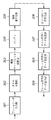
<動画像符号化装置>
図2は本実施形態における動画像符号化装置200の構成を示すブロック図であり、図2のフレームデータ符号化部202の構成を図3に示す。また、動画像符号化装置200の処理のフローチャートを図4に示す。
【0018】
まず、画像データと音声データが、画像データ取得部201と音声データ取得部203から入力される(ステップS401)。この画像データ取得部201と音声データ取得部203には、例えばデジタルビデオカメラ、デジタルスチルカメラ、スキャナ等の撮像装置、或いはCCDなどの撮像デバイス、或いはネットワーク回線のインターフェース等が用いられる。更に、画像データ取得部201と音声データ取得部203はRAM、ROM、ハードディスク、CD−ROM等の記録媒体であっても良い。図5は、画像データ取得部201及び音声データ取得部203から得られる画像データ及び音声データの概念を、時間に対応して示した図である。
【0019】
ステップS402において、画像データ取得部201から取得した画像データは、フレームデータ毎(図5(a)のフレーム毎のデータ)に、フレームデータ符号化部202に入力される。フレームデータ符号化部202に入力されたフレームデータは、圧縮処理されてフレーム符号化データとなる。また、生成された複数のフレーム符号化データは、順次、データ統合部205に入力される。
【0020】
一方、音声データ取得部203から取得された音声データは、音声データ符号化部204に入力され、後述の処理により符号化が行われ、音声符号化データとなる(ステップS402)。
【0021】
生成された音声符号化データは、データ統合部205に入力される。なお、以下の説明において音声データの符号化方法については触れないが、音声データの符号化方法として、例えば、MP3(MPEG Audio Layer III)やAAC(Advance Audio Coding)等が考えられるがこれに限るものではない。また、符号化を行わなくてもよい。
【0022】
データ統合部205に音声符号化データとフレーム符号化データが入力されると、図5(b)に示すように、フレーム符号化データと音声符号化データを所定の規則に基づいて並べる。図5(b)に示す例では、4フレーム分のフレーム符号化データ毎に、これらのフレームに対応する音声符号化データを挿入している。さらに、図6に示すように、ヘッダ等の復号に必要となるデータが所定の個所に挿入されて、動画像符号化データが生成される(ステップS403)。
【0023】
その後、生成された動画像符号化データは、動画像符号化データ出力部206から外部へ出力される(ステップS404)。この動画像符号化データ出力部206としては、例えば、公衆の電話回線、Bluetooth等の無線回線、LAN、USBやIEEE1394などの有線回線等のインターフェースを用いることができる。また、動画像符号化装置200が例えばPC1等の他の装置の内部に構成されている場合には、その装置の内部メモリに出力するインターフェースであっても良い。
【0024】
次に、フレームデータ符号化部202におけるフレームデータの符号化処理について、図3に示すフレームデータ符号部202の構成および図7のフローチャートを参照して説明する。
【0025】
以下の説明では、符号化対象となるフレームデータが8ビットのモノクロフレームデータであるものとして説明をする。しかしながら、フレームデータの形態はこれに限るものではなく、各画素4ビット、10ビット、12ビットと言った具合に8ビット以外のビット数で表すモノクロ画像、或いは各画素における各色成分(RGB/Lab/YCrCb)を8ビットで表現するカラーの多値フレームデータである場合に適用することも可能である。また、画像を構成する各画素の状態等を表す多値情報である場合、例えば各画素の色を表す多値のインデックス値である場合にも適用できる。これらに応用する場合には、各種類の多値情報を後述するモノクロフレームデータとすればよい。
【0026】
まず、画像データ取得部201からフレームデータ入力部301へ、符号化対象となる画像のフレームデータがラスタースキャン順に入力され、タイル分割部302に出力される。
【0027】
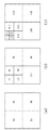
タイル分割部302は、フレームデータ入力部301から入力される1枚の画像を図8に示すようなN枚のタイルに分割し(ステップS501)、各タイルを識別するために、本第1の実施形態ではラスタースキャン順にタイル番号0, 1, 2, ...,N-1を割り振る。以下、各タイルを表すデータをタイルデータと呼ぶ。なお、図8では画像を横8縦6の48枚のタイルに分割した例を示しているが、分割タイル数は適宜変更可能であることは言うまでもない。これら生成されたタイルデータは、順に離散ウェーブレット変換部303に送られる。離散ウェーブレット変換部303以降の処理においては、タイルデータ毎に符号化される。
【0028】
ステップS502において、フレームデータ符号化部202が処理しているタイルを認識するためのカウンタをi=0に設定する。
【0029】
離散ウェーブレット変換部303は、タイル分割部302から入力される、1フレーム画像のフレームデータ中の各タイルデータ毎に複数の画素(参照画素)のデータ(以下、「参照画素データ」)を用いて離散ウェーブレット変換を行う(ステップS503)。
【0030】
ここで、離散ウェーブレット変換後のフレームデータ(離散ウェーブレット変換係数)を示す。
Y(2n) = X(2n)+floor{ (Y(2n-1)+Y(2n+1)+2)/4 }
Y(2n+1) = X(2n+1)-floor{ (X(2n)+X(2n+2))/2 } …(1)
【0031】
Y(2n),Y(2n+1)は離散ウェーブレット変換係数列であり、Y(2n)は低周波サブバンド、Y(2n+1)は高周波サブバンドである。また、上記変換式(1)においてfloor{X}はXを超えない最大の整数値を表す。この離散ウェーブレット変換を模式的に表わしたのが図9である。
【0032】
上記変換式(1)は一次元のデータに対するものであるが、この変換を水平方向、垂直方向の順に適用して二次元の変換を行うことにより、図10(a)に示す様なLL,HL,LH,HHの4つのサブバンドに分割することができる。ここで、Lは低周波サブバンド、Hは高周波サブバンドを示している。次にLLサブバンドを、同じ様にして4つのサブバンドに分け(図10(b))、その中のLLサブバンドを更に4つのサブバンドに分ける(図10(c))。このようにして合計10のサブバンドを作る。10個のサブバンドそれぞれを、図10(c)の様にHH1,HL1,…と呼ぶ。ここで、各サブバンドの名称における数字は、それぞれのサブバンドのレベルを示す。つまり、レベル1のサブバンドは、HL1,HH1,LH1、レベル2のサブバンドは、HL2,HH2,LH2、レベル3のサブバンドは、HL3,HH3,LH3である。なおLLサブバンドは、レベル0のサブバンドである。LLサブバンドは一つしかないので添字を付けない。またレベル0からレベルnまでのサブバンドを復号することで得られる復号画像を、レベルnの復号画像と呼ぶ。復号画像は、そのレベルが高い程解像度は高い。
【0033】
10個のサブバンドの変換係数は、一旦バッファ304に格納され、LL,HL1,LH1,HH1,HL2,LH2,HH2,HL3,LH3,HH3の順に、つまり、レベルが低いサブバンドからレベルが高いサブバンドの順に、係数量子化部305へ出力される。
【0034】
係数量子化部305では、バッファ304から出力される各サブバンドの変換係数を各周波数成分毎に定めた量子化ステップで量子化し、量子化後の値(係数量子化値)をエントロピー符号化部306へ出力する(ステップS504)。係数値をX、この係数の属する周波数成分に対する量子化ステップの値をqとすると、量子化後の係数値Q(X)は次式(2)によって求めるものとする。
Q(X)=floor{(X/q)+0.5} …(2)
【0035】
本第1の実施形態における各周波数成分と量子化ステップとの対応を図11に示す。同図に示すように、よりレベルが高いサブバンドの方に、大きい量子化ステップを与えている。なお、各サブバンド毎の量子化ステップは予め不図示のRAMやROMなどのメモリに格納されているものとする。そして、一つのサブバンドにおける全ての変換係数を量子化した後、それら係数量子化値をエントロピー符号化部306へ出力する。
【0036】
エントロピー符号化部306は、入力された係数量子化値をエントロピー符号化する(ステップS505)。ここでは、まず、図12に示すように、入力された係数量子化値の集まりである各サブバンドは矩形(「コードブロック」と呼ぶ。)に分割される。なお、このコードブロックの大きさには、2m×2n(m、nは2以上の整数)等が設定される。さらにこのコードブロックを、図13に示すように、ビットプレーンに分割する。その上で、各ビットプレーンにおける各ビットは、図14に示すように所定分類規則に基づいて3種類に分けられて、同じ種類のビットを集めたコーディングパスが3種類生成される。入力された係数量子化値は、ここで得られたコーディングパスを単位として、エントロピー符号化である二値算術符号化が行われ、エントロピー符号化値が生成される。
【0037】
なお、エントロピー符号化は、1つのコードブロックに注目すると上位ビットプレーンから下位ビットプレーンの順に符号化され、更にそのコードブロックのあるビットプレーンに注目すると、図14に示す3種類のパスを上から順に符号化するようになっている。
【0038】
エントロピー符号化されたコーディングパスは、タイル符号化データ生成部307に出力される。
【0039】
タイル符号化データ生成部307では、入力された複数のコーディングパスから、単一もしくは複数のレイヤーを構成し、それらレイヤーをデータの単位としてタイル符号化データを生成する(ステップS506)。以下にレイヤーの構成に関する説明を行う。
【0040】
タイル符号化データ生成部307は、図15に示すように、複数のサブバンドにおける複数のコードブロックから、エントロピー符号化されたコーディングパスを集めた上で、レイヤーを構成する。図15は5枚のレイヤーを生成する場合を示している。なお、任意のコードブロックからコーディングパスを取得する際には、図16に示すように、常にそのコードブロックにおいて最上位に存在するコーディングパスから順に選択する。その後、タイル符号化データ生成部307は、図17に示すように、生成したレイヤーを上位に位置するレイヤーから順に並べた上で、その先頭にタイルヘッダを付加してタイル符号化データを生成する。このヘッダには、タイルを識別する情報や、当該タイル符号化データの符号長や、圧縮に使用した様々なパラメータ等が格納される。このように生成されたタイル符号化データは、フレーム符号化データ生成部308に出力される。
【0041】
次に、ステップS507で符号化すべきタイルデータが残っているかどうかをカウンタiの値とタイル番号とを比較することにより判断する。符号化すべきタイルデータが残っている場合(つまりi<N−1)は、ステップS508でカウンタiを1増やし、ステップS503に戻って次のタイルに対してステップS507までの処理を繰り返す。符号化すべきタイルデータが残っていない場合(つまりi=N−1)は、ステップS509に進む。
【0042】
フレーム符号化データ生成部308では、図17に示すようなタイル符号化データを、図18に示すように所定の順番(例えば、タイル番号順)に並べた上で、先頭にヘッダを付加してフレーム符号化データを生成する(ステップS509)。このヘッダには、入力画像やタイルの縦横のサイズ、圧縮に使用した様々なパラメータ等が格納される。このように生成されたフレーム符号化データは、フレーム符号化データ出力部309からデータ統合部205に出力される。
【0043】
<動画像再生装置>
図19は本実施形態における動画像再生装置1000の構成を示すブロック図であり、図19におけるフレームデータ復号部2003の構成を図20に示す。また、この動画像再生装置1000における処理のフローチャートを図21に示す。
【0044】
まず、動画像再生装置1000がユーザーから通常再生指示部2007または高速再生指示部2008を介して通常再生もしくは高速再生の指示を受けると(ステップS2201)、動画像符号化データ取得部2001は、蓄積部2009から動画像符号化データを読み出し、分離部2002へ送信する(ステップS2202)。
【0045】
動画像符号化データを受け取った分離部2002は、該動画像符号化データをフレーム符号化データと音声符号化データに分離する(ステップS2203)。ここで生成されたフレーム符号化データはフレームデータ復号部2003へ、音声符号化データは音声データ復号部2005へ出力される。また、フレームデータ復号部2003には、フレーム符号化データと共に、ユーザーから指定された再生方法(通常再生/高速再生)の情報が伝達される。なお、音声データの再生方法は本発明の主旨から外れるので、以下の記述において音声符号化データの説明は省略する。
【0046】
分離されたフレーム符号化データの復号処理の開始にあたり、まず、ユーザーから指定された再生方法を判断する(ステップS2204)。ユーザーから通常再生が指示されている場合、フレームデータ復号部2003はフレーム符号化データを通常復号し、復号フレームデータを生成する(ステップS2205)。また、音声データ復号部2005は音声符号化データを復号し、復号音声データを生成する(ステップS2205)。
【0047】
一方、ユーザーから指示された再生方法が通常再生以外のとき(すなわち高速再生が指示された場合)、フレームデータ復号部2003はフレーム符号化データを高速復号し、復号フレームデータを生成する(ステップS2207)。なお、高速再生時には音声符号化データの復号は行わない。このときの再生速度は、ユーザーによって指定された任意の速度、あるいは表示するディスプレイの表示周波数に応じて決定する。
【0048】
ステップS2205で生成された復号フレームデータ及び復号音声データ、並びにステップS2207で高速復号された復号フレームデータは、復号フレーム出力部2004及び復号音声出力部2006からディスプレイへ出力される(ステップS2206,S2208)が、このとき高速再生したことによって表示するディスプレイの表示周波数に合致しないときは、ディスプレイの表示周波数を出力データが表示可能である最適な表示周波数に設定する(S2209)。
【0049】
次に図19のフレームデータ復号部2003で行う処理について、図20にフレームデータ復号部2003の詳細な構成を示し、図22のフローチャートを参照して説明する。
【0050】
フレーム符号化データ入力部2101に入力されたフレーム符号化データと再生方法の情報は、復号対象タイル決定部2102に出力される。復号対象タイル決定部2102は、再生方法が通常再生であれば図23(a)に示すフレーム中の全てのタイルを復号対象タイルと決定する(ステップS2501)。一方で、再生方法が高速再生であれば、図23(b)の太線で示すように、フレーム中の一部のタイルを復号対象タイルと決定する(ステップS2501)。この復号すべきタイルの決定には、メインヘッダやタイルヘッダにある情報を利用する。なお、高速再生時の図23(b)では、縦6横8の全48タイルの内、内側にある縦4横6の24タイルを処理の対象としているがこれに限るものではなく、処理部の速度に応じて、処理可能な数の任意のタイルを選択すれば良い。
【0051】
また、ここで決定される復号対象のタイルの枚数をMとし、各復号対象であるタイルを識別するために、各復号対象タイルに対して番号0〜M-1を割り振る。この番号の割り振り方は、図24に示すように、左上に存在するタイルから右に向かって、さらに上から下に向かって番号が増えるようにする。
【0052】
復号対象タイルを決定した後、フレームデータ復号部2003が処理しているタイルを認識するためのカウンタをi=0に設定する(ステップS2502)。
【0053】
次に、復号対象であるタイル符号化データは、エントロピー復号部2103に入力されて、エントロピー復号が行われ、量子化値が復元される(ステップS2503)。そして復元された量子化値は逆量子化部2104に出力される。逆量子化部2104は入力した量子化値を逆量子化することにより、離散ウェーブレット変換係数を復元して後続の逆離散ウェーブレット変換部2105に出力する(ステップS2504)。逆量子化は以下の式により行われる。
Xr=Q×q
【0054】
ただし、Qは量子化値、qは量子化ステップ、Xrは復元された離散ウェーブレット変換係数である。逆離散ウェーブレット変換部2105では、以下に記述する式に基づいて、逆離散ウェーブレット変換を行う(ステップS2505)。
X(2n)=Y(2n)-floor{(Y(2n-1)+Y(2n+1)+2)/4}
X(2n+1)=Y(2n+1)+floor{(X(2n)+X(2n+2))/2}
【0055】
ここで、低周波サブバンドの離散ウェーブレット変換係数をY(2n)、高周波サブバンドの離散ウェーブレット変換係数をY(2n+1)とする。また、X(n)は復号データである。本変換式は一次元のデ−タに対するものであるが、この変換を水平方向、垂直方向の順に適用することで二次元の変換を行う。そして復号タイルデータが生成され、復号フレームデータ出力部2106に出力される(ステップS2506)。
【0056】
次に、ステップS2507で復号対象タイルが残っているかどうかをカウンタiとタイル番号とを比較することにより判断する。復号化すべきタイルが残っている場合(つまりi<M−1)は、ステップS2508でカウンタiを1増やし、ステップS2503に戻って次のタイルに対してステップS2507までの処理を繰り返す。一方、ステップS2507で復号すべきタイルが残っていない場合(つまりi=M−1)は、ステップS2509に進む。
【0057】
復号フレームデータ出力部2106は、復号タイルデータをi=0,...,M-1の順番で並べた上で復号フレームデータを生成し、復号フレーム出力部2004に出力する。(ステップS2509)。
【0058】
本第1の実施形態では、通常再生(30fps)のときと2倍速再生(60fps)のときで異なる表示周波数で復号フレームデータが外部のディスプレイに出力されることになるが、出力したフレームデータの表示周波数に従ってディスプレイに表示周波数を切換えさせて表示させる。
【0059】
以上、本第1の実施形態によれば、高速再生時に各フレームの一部を再生することで、PCの処理性能を超えることなく、滑らかな再生画像を表示することが可能となる。
【0060】
なお、上記第1の実施形態においては、高速再生時には各フレームのブロックの内、半分の数のブロックを各フレームで再生することにより、通常再生時の2倍の速度で再生する場合について説明したが、本発明はこれに限るものではなく、例えば、各フレームの1/3,1/4の数のブロックを再生することで、3倍速、4倍速で滑らかに画像を再生することが可能である。このように、任意の割合のブロック数の画像を再生することで、所望の倍率で再生を行うようにすることができる。
【0061】
(第2の実施形態)
次に、本発明の第2の実施形態について説明する。
【0062】
第1の実施形態においては、各フレームの一部を再生することで、PCの処理能力を超えることなく、滑らかな再生画像を表示する方法を示した。
【0063】
しかし、ディスプレイが対応している垂直表示周波数によっては、第1の実施形態の方法では所望とする倍率で高速再生を実現できないこともある。例えば、第1の実施形態と同様な方法で3倍速を実現するには、ディスプレイの垂直表示周波数が90Hzに設定される必要があるが、ディスプレイが対応している垂直表示周波数が30,60,75Hzであると、この方法での3倍速は実現できない。
【0064】
しかし、各フレームの一部を復号対象とし、且つ6枚のフレームにつき1枚のフレームをスキップして復号し、復号したフレームを75Hzで表示することで、3倍速を実現することが可能となる。また、この再生方法は、垂直表示周波数30Hzで3枚に1枚を再生する方法と比較して、なめらかな動画像を表示することができる。
【0065】
このように、本第2の実施形態では、通常再生で使用する垂直表示周波数より大きい垂直周波数と、フレームをスキップしながら復号する復号方法(スキップ復号)を組み合わせて高速再生を実現する。なお、本第2の実施形態では、30,60,75Hzの垂直表示周波数に対応したディスプレイに復号画像を表示するものとして説明する。なお、このような表示を可能とする動画像符号化データは、第1の実施形態における動画像符号化装置により生成されたものを用いることが可能である。従って、本第2の実施形態の説明においては、動画像符号化装置の構成及び処理動作についての説明は省略する。
【0066】
<動画像再生装置>
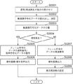
本第2の実施形態における動画像再生装置の構成は図19に示すものと同様であるが、分離部2002とフレームデータ復号部2003の動作が上記第1の実施形態と異なる。以下、本第2の実施形態における動画像再生装置の動作について図25のフローチャートを参照しながら説明する。なお、図25において図21に示す処理と同様の処理は同じステップ番号を付し、詳細説明は省略する。
【0067】
ステップS2202において、分離部2002は動画像符号化データ取得部2001から動画像符号化データを受け取ると、ステップS2600において高速再生が指示されているかどうかを判断する。高速再生が指示された場合、再生画像を表示するディスプレイで設定されている表示周波数及び該ディスプレイが対応可能な表示周波数に関する情報(以下、表示周波数情報)を受信し(ステップS2601)、その後ステップS2602に進み、受け取った動画像符号化データがスキップ対象のフレームのデータかどうかを判断する。例えば、通常再生時に30fpsで表示を行うディスプレイが75fpsでの表示が可能な場合、75/30=5/2倍速が実現される。この場合に3倍速を実現するためには、6枚に1枚のフレーム符号化データをスキップし、スキップするフレームの動画像符号化データをフレームデータ復号部2003及び音声データ復号部2005に送信しないようにする。従って、ステップS2602でスキップ対象のフレームであると判断すると、その動画像符号化データに対するそれ以上の処理を行わずに、処理を終了する。
【0068】
一方、高速再生ではない場合(ステップS2601でNO)及び、高速再生であってもスキップ対象のフレームでない場合(ステップS2602でNO)には、ステップS2203に進み、分離部2002は、該動画像符号化データをフレーム符号化データと音声符号化データに分離する。
【0069】
また、ステップS2207においては基本的に図22に示す処理を行うが、本第2の実施形態においては、ステップS2501で決定される復号対象タイルが図23(b)に示すものと異なる。
【0070】
フレームデータ復号部2003における復号対象タイル決定部2102は、本第2の実施形態においては、30fpsの通常再生が限度であるPCが75fpsで復号できるように復号対象タイルを決定する。この復号を実現するには、通常再生より75/30=5/2倍の速さで復号しなければならないため、各フレームは2/5の領域のみを復号する必要がある。そこで本第2の実施形態においては、図26に示すように、全タイル数48×2/5=約20枚のタイルを復号対象タイルとして決定する。なお、20枚のタイルの位置は、図26に示すものに限るものではなく、適宜変更可能である。
【0071】
上記のようにして復号対象タイルを決定した後、ステップS2502以降の処理は上記第1の実施形態と同様である。
【0072】
本実施の形態では、高速再生のとき再生速度に応じて異なる表示周波数で復号フレームデータが外部のディスプレイに出力されることになるが、出力したフレームデータの表示周波数に従ってディスプレイに対応する表示周波数を切換えさせて表示させる(図25のS2209)。ディスプレイの表示可能な周波数をあらかじめ知っているので、表示がエラーになることはない。
【0073】
なお、本第2の実施形態では、ディスプレイの表示周波数が30,60,75Hzである場合について説明したが、本発明はこれに限るものではなく、各フレームで復号するデータ部分の割合及び間引くフレームの割合を変更することにより、ディスプレイ及びPCの能力に合わせて再生速度を適宜調整することが可能であることは言うまでもない。
【0074】
上記の通り本第2の実施形態によれば、高速再生を行うために、各フレームの一部の復号だけでなく、所定フレーム毎にフレームをスキップする方法と組み合わせることにより、最適な倍率で高速再生を行うことが可能となる。
【0075】
(第3の実施形態)
次に、本発明の第3の実施形態について説明する。
【0076】
一般的に、タイル単位の符号化方法で得られた画像符号化データを復号した場合、得られた復号画像にはブロック歪が生じる。この歪は、再生画像の画質低減の大きな原因である。また、低ビットレートで生成された画像符号化データの復号画像においては、このノイズの程度が顕著となる。したがって、このブロック歪を出さないように画像を圧縮することは、非常に重要なことである。そこで、本第3の実施形態では、再生画像にブロック歪が出ないように、符号化時にタイル分割を実施しない符号化方法、及び、そのような方法で得られた動画像符号化データを滑らかに高速再生する方法について説明する。
【0077】
本第3の実施形態における再生システムは、基本的に第1の実施形態で図1を参照して説明したものと同様であり、PC1は、所定サイズからなる動画像符号化データの全データを最大30fps(フレーム/秒)で復号する処理能力を有し、ディスプレイの表示周波数は30Hz及び60Hzに対応しているものとする。更に、本第3の実施形態の再生システムは、通常再生を30fpsで行うものとする。
【0078】
また、PC1が滑らかな再生画像を表示するために、2倍速再生では各画像の1/2の面積に相当するデータを復号して実質的に60fpsとなるように表示する。
【0079】
まず、本第3の実施形態における動画像符号化装置について説明する。
【0080】
<動画像符号化装置>
本第3の実施形態における動画像符号化装置は、図2乃至図18を参照して説明した第1の実施形態の動画像符号化装置と基本的に同様であるが、タイル分割を行わない所が第1の実施形態と異なる。以下、第3の実施形態において特徴的な処理について説明を行う。
【0081】
まず、本第3の実施形態ではタイル分割部302でタイルの枚数をN=1として処理を行う。従って、タイル分割部302においてフレームデータ入力部302から入力される各フレーム画像に対して図8に示すような分割はなされず、離散ウェーブレット変換部303以降による処理は、各フレーム画像毎に行われる。従って、符号化によって得られる図18に示すフレーム符号化データは、タイル数1(即ち、タイル0のみ)のデータとなる。
【0082】
また、第1の実施形態における動画像再生装置は高速再生時、各画像の1/2の面積に相当するタイルを復号したが、本第3の実施形態ではタイル分割を行わないため、動画像再生装置は高速再生時、各画像の1/2の面積に相当する各サブサンドのコードブロックを復号する。そこで、本第3の実施形態における動画像符号化装置は、各フレームの動画像符号化データ中に、各コードブロックへアクセスする上で必要となる情報を埋め込む。その情報の埋め込み方法の一つとして、メインヘッダ内に、各コードブロックの位置(画像符号化データの先頭からのオフセット)を記す方法がある(方法1)。また別の方法として、以下に示すように、画像符号化データに対してデータの構成を持たせ、そのデータ構成に合わせた情報の埋め込みを行う方法がある(方法2)。
【0083】
・データの構成
本第3の実施形態における動画像符号化装置は、同じ解像度レベル、同じレイヤーに所属するコードブロックのデータを寄せ集めてパケットを構成し、各パケットの先頭にパケットヘッダを付加する。さらに、画像符号化装置は、所定の順序でパケットを並べ、先頭のパケットの直前にメインヘッダを配置する。
【0084】
・情報の埋め込み
各パケットヘッダには、対応するパケット内の各コードブロックの符号長が書き込まれる。さらに、メインヘッダに、パケットの並び方、解像度レベルの数、レイヤーの数、各パケット内に存在するコードブロックの数に相当するデータ等を書き込む。
【0085】
図29(a)は、離散ウェーブレット変換を1回行い、レイヤーを2枚生成した場合の概念図であり、図29(b)は、各サブバンドを8×6の48個のコードブロックに分割した符号化方法の概念図である。図30は上述した符号化方法により生成される画像符号化データの構成を示す概念図である。
【0086】
<動画像再生装置>
本第3の実施形態では、図30に示すようなデータ構成を有する画像符号化データを用いて、図23(b)に示されているような、原画像の1/2の面積の領域に相当するコードブロックを部分復号する。なお、本第3の実施形態における動画像再生装置の構成は図19に示すものと同様であるが、フレームデータ復号部2003の構成及び動作が上記第1の実施形態と異なる。図31は、本第3の実施形態におけるフレームデータ復号部2003の構成を示す図であり、図20に示す構成とは、復号対象タイル決定部の代わりに復号対象コードブロック決定部2102’を有するところが異なる。
【0087】
まず、高速再生に対応した、PC1上で動作する動画像ビューアーを説明する。その後、動画像符号化データの復号方法について説明する。なお動画像符号化データの復号方法については、第1の実施形態における復号方法と異なる部分について説明し、同様な動作である詳細な画像符号化データの復号方法について説明しない。
【0088】
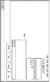
・動画像ビューアー
図32は、PC1のディスプレイに表示される操作画面を示したものである。3200は、不図示の表示用メモリに格納された画像を実際に表示する表示領域である。本第3の実施形態では、ディスプレイの画面全体ではなく、領域3200に表示される。
【0089】
3201と3202は、通常の時間軸方向への再生を指示するボタンであり、3201が通常速度の再生を指示するボタン、3202が2倍速再生を指示するボタン、3203は停止ボタンである。なお、不図示ではあるが、一時停止ボタンも存在する。
【0090】
3204と3205は、通常の時間軸方向とは逆方向への再生(逆転再生)を指示するボタンであり、3205が通常速度の逆転再生を指示するボタン、3204が2倍速逆転再生を指示するボタンである。なお、本第3の実施形態では、動画像を構成する各フレームは独立して符号化されているので、それら各フレームを逆順で復号化し表示することで、容易に逆転再生を行うことが可能である。
【0091】
・高速再生
ユーザーがボタン3202を押すことで、動画像再生装置1000は2倍速再生を実施する。ここで、「押す」とは、マウスなどのポインティングデバイスにより、ボタン3202をクリックすることを意味する。なお、以下の動作は、図21のステップS2207で行われる処理であり、その他の処理は図21を参照して説明したものと同様である。
【0092】
2倍速再生を指示された動画像再生装置1000は、図23(b)に示されているように、画像の中心で、かつ面積にして1/2の領域をコードブロック単位で復号し、さらに1/60秒のタイミングでディスプレイに1フレーム分の復号データを送信する。
【0093】
動画像再生装置1000がコードブロック単位で復号する際、動画像符号化データ中に埋め込まれている情報を利用して、必要となるコードブロックにアクセスする。例えば、動画像符号化装置が方法1で情報を埋め込んだ場合、動画像再生装置1000は、必要となるコードブロックのオフセットをメインヘッダから読み取り、その上でコードブロックを取得する。また、動画像符号化装置が方法2で情報を埋め込んだ場合、動画像再生装置1000は、図33のフローチャートに示された処理により、必要なコードブロックにアクセスし、復号する。以下、図33に示す方法2で情報を埋め込んだ場合のアクセス方法を示す。なお、ここで再生される動画像符号化データは、図29及び図30に示されている構成を有する。
【0094】
まず、復号対象コードブロック決定部2102’は、フレーム符号化データのメインヘッダから、パケットの並び方、解像度レベルの数、レイヤーの数、各パケット内に存在するコードブロックの数を取得する(ステップS3301)。次いで、取得した解像度レベルの数とレイヤーの数から、フレーム符号化データ中に存在するパケットの数Mを算出する(ステップS3302)。さらに、メインヘッダから取得したパケットの並び方から、各パケット内における、必要となるコードブロック(必要コードブロック)の順番(位置)を導出する(ステップS3303)。図34は、各パケット内における必要コードブロックの位置の概念図を示す。例えば、図34に示すパケットにHL、LH、HHのデータが入っている場合、必要コードブロックは3カ所に分散して存在している。
【0095】
次に、処理したパケットの数を示すカウンタ(counter)を0にセットし(ステップS3304)、先頭のパケットのパケットヘッダの解析を行う(ステップS3305)。このパケットヘッダの解析では、パケット内における各コードブロックの符号長を取得し、パケットヘッダの先頭に対する必要コードブロックの位置、並びにパケットヘッダの先頭に対する次のパケットの先頭の位置を求める。この求めた情報から、必要コードブロックの先頭にアクセスし、必要コードブロックを取得し(ステップS3306)、エントロピー復号部2103より後段の各処理部により復号する(ステップS3307)。
【0096】
続いて、ステップS3308でカウンタの数を評価し、もしその数がM−1より小さければ(ステップS3308でNO)、処理するパケットがまだ存在するので、カウンタ値を1増加させた上で(ステップS3309)、処理をステップS3305に戻す。一方、カウンタの数がM−1と等しければ(ステップS3308でYES)、復号フレームデータ出力部2106は、復号したコードブロック単位のデータを連結させることで復号画像を構成し(ステップS3310)、復号フレーム出力部2004(図19)へ出力する(ステップS3311)。次に、動画像再生装置1000は、ユーザーがボタン3201、3203等を押すなどして高速再生の終了の指示があるか否かを判断し(ステップS3312)、もし終了の指示がなければ(ステップS3312でNO)、次のフレームの処理を開始する(ステップS3301)。一方終了の指示があれば(ステップS3312でYES)、高速再生を終了させる。
【0097】
以上の通り、本第3の実施形態によれば、タイル単位で符号化されていない動画像符号化データを使って、滑らかに高速再生表示を実行することができる。
【0098】
(第4の実施形態)
上記第3の実施形態においては、タイル分割を行わずに符号化した動画像符号化データに対し、高速再生時、コードブロック単位で部分アクセスし、復号、表示する方法を示した。本第4の実施形態においては、符号化時に、部分復号を容易に実施するために、複数のコードブロックを集めたプリシンクトを定義し、その上で画像符号化データを生成する。さらに、そのようにして生成された動画像符号化データを用いて、滑らかな高速再生表示を行う方法について説明する。
【0099】
なお、本第4の実施形態における再生システムも、基本的に第1の実施形態で図1を参照して説明したものと同様であり、PC1は、所定サイズからなる動画像符号化データの全データを最大30fps(フレーム/秒)で復号する処理能力を有し、ディスプレイの表示周波数は30Hz及び60Hzに対応しているものとする。更に、本第4の実施形態の再生システムは、通常再生を30fpsにより行うものとする。
【0100】
また、PC1が滑らかな再生画像を表示するために、2倍速再生では各画像の1/2の面積に相当するデータを復号して実質的に60fpsとなるように表示する。ただし、図35に示すように、本第4の実施形態においては、両横1/4の面積を切り捨てた領域を高速再生に用いるものとする。
【0101】
まず、本第4の実施形態における動画像符号化装置について説明する。
【0102】
<動画像符号化装置>
本第4の実施形態における動画像符号化装置は、図2乃至図18を参照して説明した第1の実施形態の動画像符号化装置と基本的に同様であるが、第3の実施形態と同様にタイル分割を行わない所が第1の実施形態と異なり、また、動画像符号化データの構成は、第3の実施形態と異なる。以下、第4の実施形態において特徴的な処理について説明を行う。
【0103】
本第4の実施形態における動画像符号化装置はタイル分割をしないので、タイル分割部でタイルの枚数はN=1として処理を行う。また、原画像上で対応する、各サブバンドにおけるコードブロックを寄せ集めてプリシンクトデータを構成する。図36はプリシンクトデータの概念を示す図である。プリシンクトデータの構成を分かりやすく示すために、図36(a)に示す3つのレベル(レベル0、1、2)からなるサブバンドのコードブロックから、図36(b)に示す4つのプリシンクトを構成した例を示す。図36において、LL、HL、LH、HHはサブバンドの種類を示し、その後の数字はサブバンドのレベルを、更にその後の数字はコードブロックの番号を示す。なお、図35に示す再生を行う場合には図26(b)に示すように各サブバンドを48(=8×6)のコードブロックに分割し、各コードブロックについて48のプリシンクトデータを構成するか、少なくとも12(=4×3)のコードブロックに分割して、12のプリシンクトデータを構成することが好ましい。また、サブバンドのレベル数は適宜変更可能である。
【0104】
第1の実施形態における動画像再生装置は高速再生時、各画像の1/2の面積に相当するタイルを復号したが、本第4の実施形態における動画像再生装置は上述したプリシンクト構成を有する動画像符号化データを再生するために、高速再生時、各画像の1/2の面積に相当するプリシンクトデータを復号する。そこで、本第4の実施形態における動画像符号化装置は、各フレームの動画像符号化データ中に各プリシンクトデータへアクセスする上で必要となる情報を埋め込む。その情報の埋め込み方法のひとつとして、メインヘッダ内に、各プリシンクトデータの位置(画像符号化データの先頭からのオフセット)を記す方法がある(方法3)。また別の方法として、以下に示すように、画像符号化データに対してデータの構成を持たせ、そのデータ構成に合わせた情報の埋め込みを行う方法がある(方法4)。
【0105】
・データの構成
本第4の実施形態における動画像符号化装置は、同じ解像度レベル、同じレイヤー、同じプリシンクトに所属するコードブロックのデータを寄せ集めてパケットを構成し、各パケットの先頭にパケットヘッダを付加する。さらに、画像符号化装置は、所定の順序でパケットを並べ、先頭のパケットの直前にメインヘッダを配置する。
【0106】
・情報の埋め込み
各パケットヘッダには、対応するパケット内の各コードブロックの符号長が書き込まれる。さらに、メインヘッダに、パケットの並び方、解像度レベルの数、レイヤーの数、プリシンクトの数、各パケット内に存在するコードブロックの数に相当するデータ等を書き込む。
【0107】
<動画像再生装置>
本第4の実施形態における動画像再生装置の構成は図19及び図31に示すものと同様であるが、フレームデータ復号部2003の動作が第3の実施形態と異なる。以下、本第4の実施形態における動画像再生装置の動作について図37のフローチャートを参照しながら説明する。なお、図37において図33に示す処理と同様の処理には同じステップ番号を付し、詳細説明は省略する。
【0108】
本第4の実施形態では、図35に示すように、画像における太枠内の1/2の面積の領域に相当するコードブロックを部分復号するものとする。
【0109】
図37は方法4により符号化されたフレーム符号化データの復号処理を示すフローチャートである。この図37は、第3の実施形態における図33の処理に対して、ステップS3302とS3303との間にステップS3701の処理が追加されていることと、ステップS3304とS3305の間にステップS3702が追加されたものである。
【0110】
図37において、ステップS3701は、フレーム符号化データを構成するM個のパケットの内、高速再生に必要となるパケット(必要パケット)を決定する。ここで、必要パケットとは、図38において網掛けで示すプリシンクトに属するパケットのことである。ステップS3702では、処理対象のパケットが、ステップS3701で決定された必要パケットであるか否かを判断する。必要パケットである場合(ステップS3702でYES)、ステップS3305に進んで、以下第3の実施形態で説明した処理を行う。一方、必要パケットでない場合(ステップS3702でNO)、ステップS3308に進んでパケットの番号を示すカウンタ値をM‐1と比較して、M‐1より小さければステップS3309にでカウンタ値を1増加させた上でステップS3702に戻り、M‐1以上であれば、ステップS3310に進む。
【0111】
以上の通り、本第4の実施形態によれば、プリシンクトデータを利用して、滑らかに高速再生表示を実行することができる。
【0112】
なお、上記第4の実施形態では、画像の左右1/2を復号しない場合について説明したが、復号するプリシンクトは任意に設定可能であり、所望の領域について高速復号可能であることは言うまでもない。
【0113】
(第5の実施形態)
上記第1〜第4の実施形態では、高速再生を行う上で、空間的な一部分に相当するデータを復号することで高速再生を行う場合について説明した。本第5の実施形態においては、復号するデータをレイヤー単位で決定し、復号対象となったレイヤーについては、空間的位置によらず全データが復号される。以下にその方法を説明する。
【0114】
本第5の実施形態における動画像符号化装置は、第1の実施形態で説明したものと同じような方法で、動画像を構成するフレームを符号化する。ただし、本第5の実施形態における動画像符号化装置は、フレームを符号化する上で、2枚のレイヤー構成を取り、さらに2枚のレイヤーはほぼ同じ符号量となるようにする。
【0115】
本第5の実施形態における動画像再生装置は、高速再生する際、各フレームの最上位レイヤーを取得し、復号表示する。
【0116】
以上の通り、本第5の実施形態においては、レイヤーを利用して、滑らかに高速再生表示を実行することができる。
【0117】
【他の実施形態】
なお、上記第1〜第5の実施形態では、フレームデータの系列変換に離散ウェーブレット変換を使用したが、本発明はこれに限定されるわけではなく、例えば系列変換に離散コサイン変換等を使用しても構わない。
【0118】
また、上記第1乃至第5の実施形態で説明したタイル、コードブロック、プリシンクト、レイヤーの内、複数のデータ単位を使用して高速再生を実現しても構わない。
【0119】
また、本発明は、複数の機器(例えばホストコンピュータ、インターフェイス機器、リーダ、スキャナ、カメラヘッドなど)から構成されるシステムに適用しても、一つの機器(例えば、複写機、デジタルカメラなど)からなる装置の一部に適用してもよい。
【0120】
また、本発明の目的は、前述した実施形態の機能を実現するソフトウェアのプログラムコードを記録した記憶媒体(または記録媒体)を、システムあるいは装置に供給し、そのシステムあるいは装置のコンピュータ(またはCPUやMPU)が記憶媒体に格納されたプログラムコードを読み出し実行することによっても、達成されることは言うまでもない。この場合、記憶媒体から読み出されたプログラムコード自体が前述した実施形態の機能を実現することになり、そのプログラムコードを記憶した記憶媒体は本発明を構成することになる。また、コンピュータが読み出したプログラムコードを実行することにより、前述した実施形態の機能が実現されるだけでなく、そのプログラムコードの指示に基づき、コンピュータ上で稼働しているオペレーティングシステム(OS)などが実際の処理の一部または全部を行い、その処理によって前述した実施形態の機能が実現される場合も含まれることは言うまでもない。ここでプログラムコードを記憶する記憶媒体としては、例えば、フレキシブルディスク、ハードディスク、ROM、RAM、磁気テープ、不揮発性のメモリカード、CD−ROM、CD−R、DVD、光ディスク、光磁気ディスク、MOなどが考えられる。
【0121】
さらに、記憶媒体から読み出されたプログラムコードが、コンピュータに挿入された機能拡張カードやコンピュータに接続された機能拡張ユニットに備わるメモリに書込まれた後、そのプログラムコードの指示に基づき、その機能拡張カードや機能拡張ユニットに備わるCPUなどが実際の処理の一部または全部を行い、その処理によって前述した実施形態の機能が実現される場合も含まれることは言うまでもない。
【0122】
本発明を上記記憶媒体に適用する場合、その記憶媒体には、先に説明した図21又は図25および図22及び/又は図33、図37のいずれかに示すフローチャートに対応するプログラムコードが格納されることになる。
【0123】
【発明の効果】
上記の通り本発明によれば、PCのディスプレイのような複数の表示周波数を持つディスプレイに、デジタル動画像データの高速再生時に、再生した画像を滑らかに表示することが可能となる。
【0124】
また、アナログ動画像データを高速再生表示したような、デジタルの動画像データの高速再生表示が可能となる。
【図面の簡単な説明】
【図1】本発明の動画像再生装置が使用されるシステムの一形態を示す概略外観図である。
【図2】本発明の第1の実施形態における動画像符号化装置の概略構成を示すブロック図である。
【図3】本発明の第1の実施形態におけるフレームデータ符号化部の概略構成を示すブロック図である。
【図4】本発明の第1の実施形態における動画像符号化装置が行う動画像データの符号化処理のフローチャートである。
【図5】動画像符号化データ構成の説明図である。
【図6】動画像符号化データ構成の説明図である。
【図7】本発明の第1の実施形態におけるフレームデータ符号化部が行うフレームデータの符号化処理のフローチャートである。
【図8】タイル分割の説明図である。
【図9】1次元離散ウェーブレット変換の説明図である。
【図10】(a)は4つのサブバンドに分解した図、(b)は(a)のLLサブバンドを更に4つのサブバンドに分解した図、(c)は(b)のLLサブバンドを更に4つのサブバンドに分解した図である。
【図11】量子化ステップの表を示す図である。
【図12】コードブロック分割の説明図である。
【図13】ビットプレーン分割の説明図である。
【図14】コーディングパスの説明図である。
【図15】レイヤー生成の説明図である。
【図16】レイヤー生成の説明図である。
【図17】タイル符号化データの構成の説明図である。
【図18】フレーム符号化データの構成の説明図である。
【図19】本発明の第1の実施形態における動画像再生装置の概略構成を示すブロック図である。
【図20】本発明の第1の実施形態におけるフレームデータ復号部の概略構成を示すブロック図である。
【図21】本発明の第1の実施形態における動画像再生装置が行う動画像データの復号処理のフローチャートである。
【図22】本発明の第1の実施形態における高速再生時のフレームデータの復号処理を示すフローチャートである。
【図23】本発明の第1の実施形態における復号対象タイル符号化データの決定に関する説明図である。
【図24】タイル符号化データに関する識別番号の割り振りの説明図である。
【図25】本発明の第2の実施形態における動画像再生装置が行う動画像データの復号処理のフローチャートである。
【図26】本発明の第2の実施形態における復号対象タイル符号化データの決定に関する説明図である。
【図27】従来のアナログ動画像データの高速再生の再生方法の一例を示す説明図である。
【図28】従来のデジタル動画像データの高速再生方法の一例を示す説明図である。
【図29】本発明の第3の実施形態におけるにおける符号化方法の概念図である。
【図30】本発明の第3の実施形態における画像符号化データの構成を示す図である。
【図31】本発明の第3の実施形態におけるフレームデータ復号部の概略構成を示すブロック図である。
【図32】本発明の第3の実施形態における動画ビューアーを示す説明図である。
【図33】本発明の第3の実施形態における高速再生時のフレームデータの復号処理を示すフローチャートである。
【図34】本発明の第3の実施形態における復号化するコードブロック(必要コードブロック)を示す説明図である。
【図35】本発明の第4の実施形態における復号化するコードブロック(必要コードブロック)を示す説明図である。
【図36】プリシンクトを説明する図である。
【図37】本発明の第4の実施形態における高速再生時のフレームデータの復号処理を示すフローチャートである。
【図38】本発明の第4の実施形態における必要パケットを示す説明図である。
【符号の説明】
1 情報処理装置
2 ドライブ
200 動画像符号化装置
201 画像データ取得部
202 フレームデータ符号化部
203 音声データ取得部
204 音声データ符号化部
205 データ統合部
206 動画像符号化データ出力部
301 フレームデータ入力部
302 タイル分割部
303 離散ウェーブレット変換部
304 バッファ
305 係数量子化部
306 エントロピー符号化部
307 タイル符号化データ生成部
308 フレーム符号化データ生成部
309 フレーム符号化データ出力部
1000 動画像再生装置
2001 動画像符号化データ取得部
2002 分離部
2003 フレームデータ復号部
2004 復号フレーム出力部
2005 音声データ復号部
2006 復号音声出力部
2007 通常再生指示部
2008 高速再生指示部
2009 蓄積部
2101 フレーム符号化データ入力部
2102 復号対象タイル決定部
2102’ 復号対象コードブロック決定部
2103 エントロピー復号部
2104 逆量子化部
2105 逆離散ウェーブレット変換部
2106 復号フレームデータ出力部[0001]
BACKGROUND OF THE INVENTION
The present invention relates to an image reproducing apparatus and method, and more particularly to an image reproducing apparatus and method for reproducing digital moving image data at different rates.
[0002]
[Prior art]
Currently, moving images are handled in various scenes. This moving image data (moving image data) may be recorded as analog data or digital data. When the moving image data is analog data, NTSC type monitors have often been used to display reproduced images. On the other hand, when the moving image data is digital data, the reproduced image may be displayed on a display having a plurality of vertical display frequencies, such as a display connected to a PC.
[0003]
There is a method of high-speed playback that enables playback of a moving image to be started after a desired image is found. As a method for displaying analog moving image data at a high speed on an NTSC display, a method of moving a magnetic tape as a recording medium at a high speed and changing a reproduction area as shown in FIG. 27 is often used. When digital moving image data is displayed at high speed, as shown in FIG. 28, a method of reproducing while skipping a predetermined number of frames is often used. There is also known a method of dividing each frame constituting digital moving image data, synthesizing one frame for every plurality of frames, and using this as a high-speed reproduction image, and performing high-speed reproduction display like an analog moving image. (For example, refer to Patent Document 1).
[0004]
[Patent Document 1]
JP-A-8-163494
[Problems to be solved by the invention]
The high speed reproduction of the digital moving image data as described above has a problem that the reproduced image to be displayed is awkward. In addition, even when digital moving image data is played back at high speed, it is considered that there is a user who desires a conventional high speed playback display method for analog moving image data. However, in the configuration of
[0005]
The present invention has been made in view of the above problems, and an object of the present invention is to smoothly display a reproduced image on a display having a plurality of display frequencies such as a PC display at the time of high-speed reproduction of digital moving image data. And Furthermore, another object of the present invention is to enable high-speed playback display of digital moving image data such as high-speed playback display of analog moving image data.
[0006]
[Means for Solving the Problems]
In order to achieve the above object, an image reproducing apparatus for digital moving image data according to the present invention comprises: first instruction means for instructing to reproduce an image at a first frame rate; Second instruction means for instructing to reproduce an image at a high second frame rate; and when reproduction at the second frame rate is instructed, each frame image indicated by the digital moving image data Of these, the decoded frame image, and the decoded portion of the decoded frame image A selection means for selecting and selected by the selection means Decoded frame image, and decoded portion in the decoded frame image The processing means for decoding the digital moving image data corresponding to the above and reproducing the display for display, and the display image data reproduced by the processing means, the display frequency is Choice Display processing means for displaying on a possible display; And an acquisition unit that acquires information about a display frequency corresponding to the display, and the selection unit is configured to display the second frame rate and the display frequency corresponding to the display based on the information acquired by the acquisition unit. When the display does not match, the display skips some frame images according to one of the corresponding display frequencies, selects the decoded frame image, and the display according to one of the corresponding display frequencies Select the part to be decrypted .
[0007]
According to another aspect of the present invention, there is provided an instruction step of receiving an instruction to reproduce an image at a first frame rate or a second frame rate higher than the first frame rate; Each frame image indicated by the digital moving image data is instructed to be reproduced at a frame rate of Of these, the decoded frame image, and the decoded portion of the decoded frame image A selection step for selecting and selected in the selection step Decoded frame image, and decoded portion in the decoded frame image Digital video data corresponding to Decrypt, A processing step for reproduction processing for display, and display image data reproduced in the processing step are displayed at a display frequency Choice Display processing steps to be displayed on a possible display and And an acquisition step of acquiring information on a display frequency corresponding to the display, and the selection step includes a display frequency corresponding to the second frame rate and the display based on the information acquired in the acquisition step. When the display does not match, the display skips some frame images according to one of the corresponding display frequencies, selects the decoded frame image, and the display according to one of the corresponding display frequencies Select the part to be decrypted .
[0012]
In order to achieve the other object, the selection means and the selection step have a predetermined period. Decrypted Change the part.
[0013]
DETAILED DESCRIPTION OF THE INVENTION
Preferred embodiments of the present invention will be described below in detail with reference to the accompanying drawings.
[0014]
(First embodiment)
FIG. 1 is a schematic diagram showing an example of a reproduction system in which a moving image reproduction apparatus of the present invention is used. 1 is an information processing apparatus (hereinafter “PC”) such as a personal computer, and 2 is a storage such as a DVD-ROM. A drive that reads data from a medium. In the first embodiment, encoded moving image data recorded on a medium such as an HDD or a DVD-ROM provided with the PC 1 is read and decoded, and a reproduced image is displayed on a display. In the first embodiment, the PC 1 is described as having a processing capability for decoding all data of encoded data of an image having a predetermined size at a maximum of 30 fps (frames / second). In addition, the display frequency of the display corresponds to 30 Hz and 60 Hz. Furthermore, it is assumed that the playback system of the first embodiment performs normal playback at 30 fps.
[0015]
When performing double-speed reproduction in the above-described reproduction system, the processing capability of the
[0016]
Therefore, in the present embodiment, in order to display a smooth playback image, the PC 1 decodes data corresponding to a half area of each image and displays it at 60 fps in double speed playback. The method will be described below. First, a moving picture encoding apparatus that generates moving picture encoded data that can implement the present invention will be described, and then a moving picture reproducing apparatus that implements the present invention will be described. Further, in the following description, since the audio data reproduction method deviates from the essence of the present invention, details of the audio encoding method and reproduction method are not described in this specification.
[0017]
<Moving picture encoding apparatus>
FIG. 2 is a block diagram showing the configuration of the moving
[0018]
First, image data and audio data are input from the image
[0019]
In step S402, the image data acquired from the image
[0020]
On the other hand, the audio data acquired from the audio
[0021]
The generated speech encoded data is input to the
[0022]
When speech encoded data and frame encoded data are input to the
[0023]
Thereafter, the generated moving image encoded data is output from the moving image encoded
[0024]
Next, frame data encoding processing in the frame
[0025]
In the following description, it is assumed that the frame data to be encoded is 8-bit monochrome frame data. However, the form of the frame data is not limited to this, and a monochrome image represented by a number of bits other than 8 bits such as 4 bits, 10 bits, and 12 bits for each pixel, or each color component (RGB / Lab) for each pixel. / YCrCb) can also be applied to color multivalued frame data expressing 8 bits. Further, the present invention can be applied to multi-value information representing the state of each pixel constituting an image, for example, multi-value index value representing the color of each pixel. When applied to these, each type of multi-value information may be monochrome frame data described later.
[0026]
First, frame data of an image to be encoded is input from the image
[0027]
The
[0028]
In step S502, a counter for recognizing the tile being processed by the frame
[0029]
The discrete
[0030]
Here, the frame data (discrete wavelet transform coefficient) after the discrete wavelet transform is shown.
Y (2n) = X (2n) + floor {(Y (2n-1) + Y (2n + 1) +2) / 4}
Y (2n + 1) = X (2n + 1) -floor {(X (2n) + X (2n + 2)) / 2} (1)
[0031]
Y (2n) and Y (2n + 1) are discrete wavelet transform coefficient sequences, Y (2n) is a low-frequency subband, and Y (2n + 1) is a high-frequency subband. In the conversion formula (1), floor {X} represents a maximum integer value not exceeding X. FIG. 9 schematically shows the discrete wavelet transform.
[0032]
The conversion formula (1) is for one-dimensional data. By applying this conversion in the order of the horizontal direction and the vertical direction, and performing two-dimensional conversion, LL, as shown in FIG. It can be divided into four subbands HL, LH, and HH. Here, L indicates a low-frequency subband, and H indicates a high-frequency subband. Next, the LL subband is divided into four subbands in the same manner (FIG. 10B), and the LL subband is further divided into four subbands (FIG. 10C). In this way, a total of 10 subbands are created. Each of the 10 subbands is called HH1, HL1,... As shown in FIG. Here, the number in the name of each subband indicates the level of each subband. That is, the
[0033]
The transform coefficients of the 10 subbands are temporarily stored in the
[0034]
The
Q (X) = floor {(X / q) +0.5} (2)
[0035]
FIG. 11 shows the correspondence between each frequency component and the quantization step in the first embodiment. As shown in the figure, a larger quantization step is given to a sub-band having a higher level. Note that the quantization step for each subband is stored in advance in a memory such as a RAM or a ROM (not shown). Then, after quantizing all the transform coefficients in one subband, the coefficient quantized values are output to the
[0036]
The
[0037]
Note that entropy encoding is performed in order from the upper bit plane to the lower bit plane when attention is paid to one code block. Further, when attention is paid to a bit plane having the code block, the three types of paths shown in FIG. The encoding is performed in order.
[0038]
The coding path subjected to entropy encoding is output to the tile encoded
[0039]
The tile encoded
[0040]
As shown in FIG. 15, the tile encoded
[0041]
Next, in step S507, it is determined whether the tile data to be encoded remains by comparing the value of the counter i with the tile number. If tile data to be encoded remains (that is, i <N−1), the counter i is incremented by 1 in step S508, and the process returns to step S503 to repeat the processing up to step S507 for the next tile. If no tile data to be encoded remains (that is, i = N−1), the process proceeds to step S509.
[0042]
The frame encoded
[0043]
<Video playback device>
FIG. 19 is a block diagram showing the configuration of the moving
[0044]
First, when the moving
[0045]
The
[0046]
In starting the decoding process of the separated frame encoded data, first, a reproduction method designated by the user is determined (step S2204). When normal playback is instructed by the user, the frame
[0047]
On the other hand, when the reproduction method instructed by the user is other than normal reproduction (that is, when high-speed reproduction is instructed), the frame
[0048]
The decoded frame data and decoded audio data generated in step S2205 and the decoded frame data decoded at high speed in step S2207 are output from the decoded
[0049]
Next, processing performed by the frame
[0050]
The frame encoded data and the reproduction method information input to the frame encoded
[0051]
Also, the number of decoding target tiles determined here is M, and
[0052]
After determining the decoding target tile, a counter for recognizing the tile processed by the frame
[0053]
Next, the tile encoded data to be decoded is input to the
Xr = Q × q
[0054]
However, Q is a quantization value, q is a quantization step, and Xr is a restored discrete wavelet transform coefficient. The inverse discrete
X (2n) = Y (2n) -floor {(Y (2n-1) + Y (2n + 1) +2) / 4}
X (2n + 1) = Y (2n + 1) + floor {(X (2n) + X (2n + 2)) / 2}
[0055]
Here, the discrete wavelet transform coefficient of the low frequency subband is Y (2n), and the discrete wavelet transform coefficient of the high frequency subband is Y (2n + 1). X (n) is decoded data. This conversion formula is for one-dimensional data, but two-dimensional conversion is performed by applying this conversion in the order of horizontal direction and vertical direction. Decoded tile data is generated and output to the decoded frame data output unit 2106 (step S2506).
[0056]
In step S2507, it is determined whether the decoding target tile remains by comparing the counter i with the tile number. When tiles to be decoded remain (that is, i <M−1), the counter i is incremented by 1 in step S2508, and the process returns to step S2503 to repeat the processing up to step S2507 for the next tile. On the other hand, if no tile to be decoded remains in step S2507 (that is, i = M−1), the process proceeds to step S2509.
[0057]
The decoded frame
[0058]
In the first embodiment, decoded frame data is output to an external display at different display frequencies during normal playback (30 fps) and double speed playback (60 fps). The display frequency is switched and displayed on the display according to the display frequency.
[0059]
As described above, according to the first embodiment, it is possible to display a smooth reproduced image without exceeding the processing performance of the PC by reproducing a part of each frame during high-speed reproduction.
[0060]
In the first embodiment, a case has been described in which half the number of blocks in each frame during high-speed playback is played back in each frame, so that playback is performed at twice the normal playback speed. However, the present invention is not limited to this. For example, by reproducing 1/3 and 1/4 blocks of each frame, it is possible to smoothly reproduce images at 3 × speed and 4 × speed. is there. In this way, it is possible to perform reproduction at a desired magnification by reproducing an image having an arbitrary ratio of the number of blocks.
[0061]
(Second Embodiment)
Next, a second embodiment of the present invention will be described.
[0062]
In the first embodiment, a method of displaying a smooth reproduction image by reproducing a part of each frame without exceeding the processing capability of the PC has been described.
[0063]
However, depending on the vertical display frequency supported by the display, the method of the first embodiment may not be able to realize high-speed playback at a desired magnification. For example, in order to realize the triple speed by the same method as in the first embodiment, the vertical display frequency of the display needs to be set to 90 Hz, but the vertical display frequency supported by the display is 30,60, If it is 75 Hz, the triple speed by this method cannot be realized.
[0064]
However, by decoding a part of each frame and decoding by skipping one frame out of 6 frames and displaying the decoded frame at 75 Hz, it is possible to realize triple speed. . In addition, this playback method can display a smooth moving image as compared with a method of playing back one in three at a vertical display frequency of 30 Hz.
[0065]
As described above, in the second embodiment, high-speed playback is realized by combining a vertical frequency larger than the vertical display frequency used in normal playback and a decoding method (skip decoding) for decoding while skipping frames. In the second embodiment, description will be made assuming that the decoded image is displayed on a display corresponding to a vertical display frequency of 30, 60, and 75 Hz. In addition, as the moving image encoded data that enables such display, data generated by the moving image encoding device in the first embodiment can be used. Therefore, in the description of the second embodiment, the description of the configuration and processing operation of the moving image encoding device is omitted.
[0066]
<Video playback device>
The configuration of the moving image playback apparatus in the second embodiment is the same as that shown in FIG. 19, but the operations of the
[0067]
In step S2202, when receiving the moving image encoded data from the moving image encoded
[0068]
On the other hand, if it is not high-speed playback (NO in step S2601), or if it is not high-speed playback but a frame to be skipped (NO in step S2602), the process proceeds to step S2203, and the
[0069]
In step S2207, the process shown in FIG. 22 is basically performed. In the second embodiment, the decoding target tile determined in step S2501 is different from that shown in FIG.
[0070]
In the second embodiment, the decoding target
[0071]
After determining the decoding target tile as described above, the processing after step S2502 is the same as that in the first embodiment.
[0072]
In the present embodiment, decoded frame data is output to an external display at a different display frequency according to the playback speed during high-speed playback, but the display frequency corresponding to the display is set according to the display frequency of the output frame data. The display is switched (S2209 in FIG. 25). Since the displayable frequency is known in advance, the display does not cause an error.
[0073]
In the second embodiment, the case where the display frequency of the display is 30, 60, and 75 Hz has been described. However, the present invention is not limited to this, and the ratio of the data portion to be decoded in each frame and the thinned frame It goes without saying that the playback speed can be appropriately adjusted in accordance with the capabilities of the display and the PC by changing the ratio.
[0074]
As described above, according to the second embodiment, in order to perform high-speed playback, not only a partial decoding of each frame but also a method of skipping a frame every predetermined frame makes it possible to perform high-speed reproduction at an optimum magnification. Playback can be performed.
[0075]
(Third embodiment)
Next, a third embodiment of the present invention will be described.
[0076]
Generally, when image encoded data obtained by an encoding method in units of tiles is decoded, block distortion occurs in the obtained decoded image. This distortion is a major cause of a reduction in the quality of the reproduced image. In addition, the degree of noise becomes significant in a decoded image of encoded image data generated at a low bit rate. Therefore, it is very important to compress an image so as not to generate this block distortion. Therefore, in the third embodiment, an encoding method that does not perform tile division at the time of encoding so that block distortion does not appear in a reproduced image, and moving image encoded data obtained by such a method are smoothed. Next, a method for high-speed playback will be described.
[0077]
The playback system in the third embodiment is basically the same as that described with reference to FIG. 1 in the first embodiment, and the
[0078]
In addition, in order to display a smooth reproduced image, the
[0079]
First, the moving picture coding apparatus according to the third embodiment will be described.
[0080]
<Moving picture encoding apparatus>
The moving picture coding apparatus according to the third embodiment is basically the same as the moving picture coding apparatus according to the first embodiment described with reference to FIGS. 2 to 18, but does not perform tile division. This is different from the first embodiment. Hereinafter, characteristic processing in the third embodiment will be described.
[0081]
First, in the third embodiment, the
[0082]
In addition, the moving image playback apparatus according to the first embodiment decodes tiles corresponding to a half area of each image during high-speed playback. However, since the tile division is not performed in the third embodiment, the moving image playback device At the time of high-speed playback, the playback device decodes the code block of each subsand corresponding to 1/2 the area of each image. Therefore, the moving picture coding apparatus according to the third embodiment embeds information necessary for accessing each code block in the moving picture coded data of each frame. As one of the information embedding methods, there is a method of writing the position of each code block (offset from the head of the encoded image data) in the main header (method 1). As another method, as shown below, there is a method in which image encoded data has a data configuration and information is embedded in accordance with the data configuration (method 2).
[0083]
Data structure
The moving picture coding apparatus according to the third embodiment forms a packet by collecting data of code blocks belonging to the same resolution level and the same layer, and adds a packet header to the head of each packet. Further, the image coding apparatus arranges packets in a predetermined order and arranges a main header immediately before the first packet.
[0084]
・ Embedding information
In each packet header, the code length of each code block in the corresponding packet is written. Further, the data such as the arrangement of packets, the number of resolution levels, the number of layers, the number of code blocks existing in each packet, and the like are written in the main header.
[0085]
FIG. 29A is a conceptual diagram when discrete wavelet transform is performed once to generate two layers. FIG. 29B is a diagram in which each subband is divided into 48 code blocks of 8 × 6. It is a conceptual diagram of the encoding method performed. FIG. 30 is a conceptual diagram showing a configuration of encoded image data generated by the above-described encoding method.
[0086]
<Video playback device>
In the third embodiment, image encoded data having a data configuration as shown in FIG. 30 is used, and an area having an area of ½ of the original image as shown in FIG. 23B is used. The corresponding code block is partially decoded. The configuration of the moving image playback apparatus in the third embodiment is the same as that shown in FIG. 19, but the configuration and operation of the frame
[0087]
First, a moving image viewer that operates on the
[0088]
・ Video viewer
FIG. 32 shows an operation screen displayed on the display of the
[0089]
3201 and 3202 are buttons for instructing reproduction in the normal time axis direction, 3201 is a button for instructing reproduction at normal speed, 3202 is a button for instructing reproduction at double speed, and 3203 is a stop button. Although not shown, there is also a pause button.
[0090]
3204 and 3205 are buttons for instructing reproduction (reverse reproduction) in the direction opposite to the normal time axis direction, 3205 is a button for instructing normal speed reverse reproduction, and 3204 is a button for instructing double-speed reverse reproduction. It is. In the third embodiment, since each frame constituting a moving image is independently encoded, it is possible to easily perform reverse reproduction by decoding and displaying each frame in reverse order. It is.
[0091]
・ High-speed playback
When the user presses a
[0092]
As shown in FIG. 23 (b), the moving
[0093]
When the moving
[0094]
First, the decoding target code
[0095]
Next, a counter indicating the number of processed packets is set to 0 (step S3304), and the packet header of the first packet is analyzed (step S3305). In this packet header analysis, the code length of each code block in the packet is acquired, and the position of the necessary code block with respect to the head of the packet header and the position of the head of the next packet with respect to the head of the packet header are obtained. From the obtained information, the head of the necessary code block is accessed to obtain the necessary code block (step S3306), and the
[0096]
Subsequently, the number of counters is evaluated in step S3308. If the number is smaller than M-1 (NO in step S3308), there is still a packet to be processed, and the counter value is incremented by 1 (step In step S3309, the process returns to step S3305. On the other hand, if the number of counters is equal to M−1 (YES in step S3308), decoded frame
[0097]
As described above, according to the third embodiment, high-speed playback display can be smoothly executed using moving image encoded data that is not encoded in units of tiles.
[0098]
(Fourth embodiment)
In the third embodiment, a method has been described in which moving image encoded data encoded without tile division is partially accessed, decoded, and displayed in units of code blocks during high-speed playback. In the fourth embodiment, in order to easily perform partial decoding at the time of encoding, a precinct obtained by collecting a plurality of code blocks is defined, and image encoded data is generated thereon. Furthermore, a method for performing smooth high-speed playback display using the moving image encoded data generated as described above will be described.
[0099]
Note that the playback system in the fourth embodiment is basically the same as that described with reference to FIG. 1 in the first embodiment, and the
[0100]
In addition, in order to display a smooth reproduced image, the
[0101]
First, the moving picture coding apparatus according to the fourth embodiment will be described.
[0102]
<Moving picture encoding apparatus>
The moving image encoding apparatus according to the fourth embodiment is basically the same as the moving image encoding apparatus according to the first embodiment described with reference to FIGS. 2 to 18, but the third embodiment. Similarly to the first embodiment, the tile division is not performed, and the configuration of the moving image encoded data is different from that of the third embodiment. Hereinafter, characteristic processing in the fourth embodiment will be described.
[0103]
Since the moving image coding apparatus according to the fourth embodiment does not perform tile division, the tile division unit performs processing with N = 1 as the number of tiles. Also, precinct data is configured by collecting code blocks in each subband corresponding to each other on the original image. FIG. 36 shows the concept of precinct data. In order to show the structure of the precinct data in an easy-to-understand manner, four precincts shown in FIG. 36 (b) are obtained from the subband code block consisting of three levels (
[0104]
The moving image reproducing apparatus according to the first embodiment decodes tiles corresponding to a half area of each image during high-speed reproduction, but the moving image reproducing apparatus according to the fourth embodiment has the above-described precinct configuration. In order to reproduce the moving image encoded data, precinct data corresponding to half the area of each image is decoded during high-speed reproduction. Therefore, the moving picture coding apparatus according to the fourth embodiment embeds information necessary for accessing each precinct data in the moving picture coded data of each frame. As one of the information embedding methods, there is a method of marking the position of each precinct data (offset from the head of the encoded image data) in the main header (method 3). As another method, as shown below, there is a method in which image encoded data has a data structure and information is embedded in accordance with the data structure (method 4).
[0105]
Data structure
The moving picture coding apparatus according to the fourth embodiment forms a packet by collecting data of code blocks belonging to the same resolution level, the same layer, and the same precinct, and adds a packet header to the head of each packet. Further, the image coding apparatus arranges packets in a predetermined order and arranges a main header immediately before the first packet.
[0106]
・ Embedding information
In each packet header, the code length of each code block in the corresponding packet is written. Further, in the main header, data such as the arrangement of packets, the number of resolution levels, the number of layers, the number of precincts, and the number of code blocks existing in each packet are written.
[0107]
<Video playback device>
The configuration of the moving image playback apparatus in the fourth embodiment is the same as that shown in FIGS. 19 and 31, but the operation of the frame
[0108]
In the fourth embodiment, as shown in FIG. 35, it is assumed that a code block corresponding to a 1/2 area area within a thick frame in an image is partially decoded.
[0109]
FIG. 37 is a flowchart showing a decoding process of frame encoded data encoded by the
[0110]
In FIG. 37, step S3701 determines a packet (necessary packet) necessary for high-speed reproduction among M packets constituting frame encoded data. Here, the necessary packet is a packet belonging to a precinct indicated by shading in FIG. In step S3702, it is determined whether the processing target packet is the necessary packet determined in step S3701. If the packet is a necessary packet (YES in step S3702), the process advances to step S3305 to perform the process described in the third embodiment. On the other hand, if the packet is not a necessary packet (NO in step S3702), the flow advances to step S3308 to compare the counter value indicating the packet number with M-1, and if it is smaller than M-1, the counter value is incremented by 1 in step S3309. After that, it returns to step S3702 and M-1 more than If so, the process proceeds to step S3310.
[0111]
As described above, according to the fourth embodiment, high-speed playback display can be smoothly executed using precinct data.
[0112]
In the fourth embodiment, the case where the left and right half of the image is not decoded has been described, but it is needless to say that the precinct to be decoded can be arbitrarily set, and high-speed decoding can be performed for a desired region.
[0113]
(Fifth embodiment)
In the first to fourth embodiments, the case has been described in which high-speed reproduction is performed by decoding data corresponding to a spatial portion in performing high-speed reproduction. In the fifth embodiment, the data to be decoded is determined in units of layers, and all data is decoded for the decoding target layer regardless of the spatial position. The method will be described below.
[0114]
The moving image encoding apparatus according to the fifth embodiment encodes frames constituting a moving image by a method similar to that described in the first embodiment. However, the moving picture coding apparatus according to the fifth embodiment takes two layers when coding a frame, and the two layers have almost the same code amount.
[0115]
The moving image playback apparatus according to the fifth embodiment acquires the highest layer of each frame and decodes and displays it when performing high-speed playback.
[0116]
As described above, in the fifth embodiment, high-speed playback display can be executed smoothly using layers.
[0117]
[Other Embodiments]
In the first to fifth embodiments, the discrete wavelet transform is used for the frame data sequence conversion. However, the present invention is not limited to this. For example, the discrete cosine transform or the like is used for the sequence conversion. It doesn't matter.
[0118]
Further, high-speed playback may be realized using a plurality of data units among the tiles, code blocks, precincts, and layers described in the first to fifth embodiments.
[0119]
The present invention can be applied to a system composed of a plurality of devices (for example, a host computer, an interface device, a reader, a scanner, a camera head, etc.), but from a single device (for example, a copying machine, a digital camera). The present invention may be applied to a part of the device.
[0120]
Another object of the present invention is to supply a storage medium (or recording medium) in which a program code of software that realizes the functions of the above-described embodiments is recorded to a system or apparatus, and the computer (or CPU or CPU) of the system or apparatus. Needless to say, this can also be achieved by the MPU) reading and executing the program code stored in the storage medium. In this case, the program code itself read from the storage medium realizes the functions of the above-described embodiments, and the storage medium storing the program code constitutes the present invention. Further, by executing the program code read by the computer, not only the functions of the above-described embodiments are realized, but also an operating system (OS) running on the computer based on the instruction of the program code. It goes without saying that a case where the function of the above-described embodiment is realized by performing part or all of the actual processing and the processing is included. Examples of the storage medium for storing the program code include a flexible disk, hard disk, ROM, RAM, magnetic tape, nonvolatile memory card, CD-ROM, CD-R, DVD, optical disk, magneto-optical disk, MO, and the like. Can be considered.
[0121]
Furthermore, after the program code read from the storage medium is written into a memory provided in a function expansion card inserted into the computer or a function expansion unit connected to the computer, the function is determined based on the instruction of the program code. It goes without saying that the CPU or the like provided in the expansion card or the function expansion unit performs part or all of the actual processing and the functions of the above-described embodiments are realized by the processing.
[0122]
When the present invention is applied to the above-described storage medium, the storage medium stores program codes corresponding to the flowcharts shown in FIG. 21 or FIG. 25 and FIG. 22 and / or FIG. 33 and FIG. Will be.
[0123]
【The invention's effect】
As described above, according to the present invention, a reproduced image can be smoothly displayed on a display having a plurality of display frequencies such as a PC display at the time of high-speed reproduction of digital moving image data.
[0124]
Further, high-speed playback display of digital moving image data, such as high-speed playback display of analog moving image data, is possible.
[Brief description of the drawings]
FIG. 1 is a schematic external view showing an embodiment of a system in which a moving image reproduction apparatus of the present invention is used.
FIG. 2 is a block diagram showing a schematic configuration of a moving picture coding apparatus according to the first embodiment of the present invention.
FIG. 3 is a block diagram showing a schematic configuration of a frame data encoding unit in the first embodiment of the present invention.
FIG. 4 is a flowchart of moving image data encoding processing performed by the moving image encoding apparatus according to the first embodiment of the present invention.
FIG. 5 is an explanatory diagram of a moving image encoded data configuration.
FIG. 6 is an explanatory diagram of a moving image encoded data configuration.
FIG. 7 is a flowchart of frame data encoding processing performed by a frame data encoding unit according to the first embodiment of the present invention.
FIG. 8 is an explanatory diagram of tile division.
FIG. 9 is an explanatory diagram of a one-dimensional discrete wavelet transform.
FIGS. 10A and 10B are diagrams in which the LL subband is decomposed into four subbands, FIG. 10B is a diagram in which the LL subband in FIG. 10A is further decomposed into four subbands, and FIG. 10C is the LL subband in FIG. Is a diagram further broken down into four subbands.
FIG. 11 is a diagram showing a table of quantization steps.
FIG. 12 is an explanatory diagram of code block division.
FIG. 13 is an explanatory diagram of bit-plane division.
FIG. 14 is an explanatory diagram of a coding pass.
FIG. 15 is an explanatory diagram of layer generation.
FIG. 16 is an explanatory diagram of layer generation.
FIG. 17 is an explanatory diagram of a structure of tile encoded data.
FIG. 18 is an explanatory diagram of a configuration of frame encoded data.
FIG. 19 is a block diagram illustrating a schematic configuration of a moving image reproduction apparatus according to the first embodiment of the present invention.
FIG. 20 is a block diagram illustrating a schematic configuration of a frame data decoding unit according to the first embodiment of the present invention.
FIG. 21 is a flowchart of moving image data decoding processing performed by the moving image reproducing device according to the first embodiment of the present invention;
FIG. 22 is a flowchart showing frame data decoding processing during high-speed playback according to the first embodiment of the present invention.
FIG. 23 is an explanatory diagram regarding determination of decoding target tile encoded data according to the first embodiment of the present invention;
FIG. 24 is an explanatory diagram of allocation of identification numbers related to tile encoded data.
FIG. 25 is a flowchart of moving image data decoding processing performed by the moving image playback device according to the second embodiment of the present invention;
FIG. 26 is an explanatory diagram regarding determination of decoding target tile encoded data according to the second embodiment of the present invention;
FIG. 27 is an explanatory diagram showing an example of a conventional reproduction method for high-speed reproduction of analog moving image data.
FIG. 28 is an explanatory diagram showing an example of a conventional high-speed playback method for digital moving image data.
FIG. 29 is a conceptual diagram of an encoding method according to the third embodiment of the present invention.
FIG. 30 is a diagram illustrating a configuration of encoded image data according to the third embodiment of the present invention.
FIG. 31 is a block diagram illustrating a schematic configuration of a frame data decoding unit according to a third embodiment of the present invention.
FIG. 32 is an explanatory diagram showing a moving image viewer according to the third embodiment of the present invention.
FIG. 33 is a flowchart showing a frame data decoding process during high-speed playback in the third embodiment of the present invention.
FIG. 34 is an explanatory diagram showing a code block (necessary code block) to be decoded in the third embodiment of the present invention.
FIG. 35 is an explanatory diagram showing a code block (necessary code block) to be decoded in the fourth embodiment of the present invention.
FIG. 36 is a diagram illustrating precinct.
FIG. 37 is a flowchart showing frame data decoding processing during high-speed playback according to the fourth embodiment of the present invention.
FIG. 38 is an explanatory diagram showing necessary packets in the fourth embodiment of the present invention;
[Explanation of symbols]
1 Information processing equipment
2 drive
200 moving picture coding apparatus
201 Image data acquisition unit
202 Frame data encoding unit
203 Voice data acquisition unit
204 Voice data encoding unit
205 Data Integration Department
206 Video encoded data output unit
301 Frame data input section
302 tile division
303 Discrete wavelet transform unit
304 buffers
305 Coefficient quantization unit
306 Entropy encoding unit
307 Tile encoded data generation unit
308 Frame encoded data generator
309 frame encoded data output unit
1000 Moving image playback device
2001 moving image encoded data acquisition unit
2002 Separation part
2003 Frame data decoding unit
2004 Decoding frame output unit
2005 voice data decoder
2006 Decoded voice output unit
2007 Normal playback instruction section
2008 High-speed playback instruction section
2009 Storage unit
2101 Frame encoded data input unit
2102 Decoding target tile determination unit
2102 'decoding object code block determination part
2103 Entropy decoding unit
2104 Inverse quantization unit
2105 Inverse discrete wavelet transform unit
2106 Decoded frame data output unit
Claims (17)
第1のフレームレートで画像を再生するように指示する第1の指示手段と、
前記第1のフレームレートよりも高い第2のフレームレートで画像を再生するように指示する第2の指示手段と、
前記第2のフレームレートによる再生が指示されている場合に、前記デジタル動画像データが示す各フレーム画像のうち、復号されるフレーム画像、及び、当該復号されるフレーム画像中の復号される部分を選択する選択手段と、
前記選択手段により選択された復号されるフレーム画像、及び、当該復号されるフレーム画像中の復号される部分に対応するデジタル動画像データを復号し、表示用に再生処理する処理手段と、
前記処理手段で再生処理された表示画像データを、表示周波数が選択可能なディスプレイ上で表示させる表示処理手段と、
前記ディスプレイが対応する表示周波数に関する情報を取得する取得手段とを有し、
前記選択手段は、前記取得手段によって取得した情報に基づいて、前記第2のフレームレートと前記ディスプレイが対応する表示周波数とが合致しないときには、前記ディスプレイが対応する表示周波数の一つに従って、一部のフレーム画像をスキップして前記復号されるフレーム画像を選択し、かつ前記ディスプレイが対応する表示周波数の一つに従って、前記復号される部分を選択することを特徴とする画像再生装置。An image playback device for digital moving image data,
First instruction means for instructing to reproduce an image at a first frame rate;
Second instruction means for instructing to reproduce an image at a second frame rate higher than the first frame rate;
When playback at the second frame rate is instructed, out of each frame image indicated by the digital moving image data , a decoded frame image and a decoded portion in the decoded frame image A selection means to select;
Processing means for decoding the decoded frame image selected by the selection means and the digital moving image data corresponding to the portion to be decoded in the decoded frame image, and performing reproduction processing for display;
Display processing means for displaying the display image data reproduced by the processing means on a display having a selectable display frequency ;
Obtaining means for obtaining information on a display frequency corresponding to the display;
When the second frame rate and the display frequency corresponding to the display do not match based on the information acquired by the acquisition unit, the selection unit is partially configured according to one of the display frequencies corresponding to the display. An image reproducing apparatus , wherein the frame image to be decoded is selected by skipping the frame image and the portion to be decoded is selected according to one of display frequencies corresponding to the display .
前記出力手段から出力される画像データのフレームレートに従って、前記表示処理手段は前記ディスプレイの表示周波数を設定させることを特徴とする請求項1乃至7のいずれか1項に記載の画像再生装置。It further has an output means for the image data processed by the processing means ,
In accordance with the frame rate of the image data output from the output means, the display processing unit image reproducing apparatus according to any one of claims 1 to 7, characterized in that to set the display frequency of the display.
第1のフレームレートまたは前記第1のフレームレートよりも高い第2のフレームレートで画像を再生する指示を受ける指示工程と、
前記第2のフレームレートによる再生が指示されている場合に、前記デジタル動画像データが示す各フレーム画像のうち、復号されるフレーム画像、及び、当該復号されるフレーム画像中の復号される部分を選択する選択工程と、
前記選択工程で選択された復号されるフレーム画像、及び、当該復号されるフレーム画像中の復号される部分に対応するデジタル動画像データを復号し、表示用に再生処理する処理工程と、
前記処理工程で再生処理された表示画像データを、表示周波数が選択可能なディスプレイ上で表示させる表示処理工程と、
前記ディスプレイが対応する表示周波数に関する情報を取得する取得工程とを有し、
前記選択工程では、前記取得工程で取得した情報に基づいて、前記第2のフレームレートと前記ディスプレイが対応する表示周波数とが合致しないときには、前記ディスプレイが対応する表示周波数の一つに従って、一部のフレーム画像をスキップして前記復号されるフレーム画像を選択し、かつ前記ディスプレイが対応する表示周波数の一つに従って、前記復号される部分を選択することを特徴とする画像再生方法。An image reproduction method for digital moving image data,
An instruction step of receiving an instruction to reproduce an image at a first frame rate or a second frame rate higher than the first frame rate;
When playback at the second frame rate is instructed, out of each frame image indicated by the digital moving image data , a decoded frame image and a decoded portion in the decoded frame image A selection process to select;
A processing step of decoding the decoded frame image selected in the selection step and the digital moving image data corresponding to the decoded portion of the decoded frame image, and reproducing the display for display;
A display processing step of displaying the display image data reproduced in the processing step on a display capable of selecting a display frequency ;
Obtaining information related to the display frequency corresponding to the display,
In the selection step, when the second frame rate and the display frequency corresponding to the display do not match based on the information acquired in the acquisition step, a part of the display frequency corresponds to the display frequency corresponding to the display. A method of reproducing an image , wherein the frame image to be decoded is selected by skipping the frame image and the portion to be decoded is selected according to one of display frequencies corresponding to the display .
Priority Applications (2)
| Application Number | Priority Date | Filing Date | Title |
|---|---|---|---|
| JP2003116049A JP4155566B2 (en) | 2002-05-31 | 2003-04-21 | Image reproducing apparatus and method |
| US10/441,050 US7466899B2 (en) | 2002-05-31 | 2003-05-20 | Image playback apparatus and method |
Applications Claiming Priority (2)
| Application Number | Priority Date | Filing Date | Title |
|---|---|---|---|
| JP2002160392 | 2002-05-31 | ||
| JP2003116049A JP4155566B2 (en) | 2002-05-31 | 2003-04-21 | Image reproducing apparatus and method |
Publications (3)
| Publication Number | Publication Date |
|---|---|
| JP2004056761A JP2004056761A (en) | 2004-02-19 |
| JP2004056761A5 JP2004056761A5 (en) | 2006-06-15 |
| JP4155566B2 true JP4155566B2 (en) | 2008-09-24 |
Family
ID=29738315
Family Applications (1)
| Application Number | Title | Priority Date | Filing Date |
|---|---|---|---|
| JP2003116049A Expired - Fee Related JP4155566B2 (en) | 2002-05-31 | 2003-04-21 | Image reproducing apparatus and method |
Country Status (2)
| Country | Link |
|---|---|
| US (1) | US7466899B2 (en) |
| JP (1) | JP4155566B2 (en) |
Families Citing this family (8)
| Publication number | Priority date | Publication date | Assignee | Title |
|---|---|---|---|---|
| JP4471337B2 (en) | 2002-08-01 | 2010-06-02 | キヤノン株式会社 | Image processing apparatus and method, computer program, and computer-readable storage medium |
| JP4491777B2 (en) * | 2004-06-04 | 2010-06-30 | 富士ゼロックス株式会社 | Image display device, image display method and program thereof |
| JP2007074037A (en) | 2005-09-02 | 2007-03-22 | Sony Corp | Information reproducing apparatus and information reproducing method, and computer program |
| US8200062B2 (en) * | 2006-04-21 | 2012-06-12 | Panasonic Corporation | Playback apparatus, program, and playback method |
| JP5183231B2 (en) * | 2008-02-05 | 2013-04-17 | キヤノン株式会社 | Video playback apparatus and control method |
| US8254755B2 (en) * | 2009-08-27 | 2012-08-28 | Seiko Epson Corporation | Method and apparatus for displaying 3D multi-viewpoint camera video over a network |
| KR20150018029A (en) * | 2013-08-08 | 2015-02-23 | 삼성디스플레이 주식회사 | Terminal and control method thereof |
| JP6564314B2 (en) * | 2015-11-27 | 2019-08-21 | キヤノン株式会社 | Image encoding apparatus, control method thereof, program, and storage medium |
Family Cites Families (7)
| Publication number | Priority date | Publication date | Assignee | Title |
|---|---|---|---|---|
| US6009236A (en) * | 1994-09-26 | 1999-12-28 | Mitsubishi Denki Kabushiki Kaisha | Digital video signal record and playback device and method for giving priority to a center of an I frame |
| JPH08163494A (en) | 1994-12-01 | 1996-06-21 | Matsushita Electric Ind Co Ltd | Device and method for generating video data |
| JPH09139943A (en) | 1995-11-16 | 1997-05-27 | Matsushita Electric Ind Co Ltd | Image companding device |
| JP3805985B2 (en) * | 1999-02-18 | 2006-08-09 | 株式会社東芝 | Stream data information storage medium, recording method, reproducing method, recording apparatus, and reproducing apparatus |
| JP2001054066A (en) | 1999-08-11 | 2001-02-23 | Toshiba Corp | Decoder and image display system and method |
| JP2002010216A (en) | 2000-04-20 | 2002-01-11 | Canon Inc | Decoding apparatus, control method and storage medium |
| US7035526B2 (en) * | 2001-02-09 | 2006-04-25 | Microsoft Corporation | Advancing playback of video data based on parameter values of video data |
-
2003
- 2003-04-21 JP JP2003116049A patent/JP4155566B2/en not_active Expired - Fee Related
- 2003-05-20 US US10/441,050 patent/US7466899B2/en not_active Expired - Fee Related
Also Published As
| Publication number | Publication date |
|---|---|
| US20030231865A1 (en) | 2003-12-18 |
| JP2004056761A (en) | 2004-02-19 |
| US7466899B2 (en) | 2008-12-16 |
Similar Documents
| Publication | Publication Date | Title |
|---|---|---|
| JP2004221999A (en) | Image processing method | |
| KR101226748B1 (en) | Remote edition system, main edition device, remote edition device, edition method, and recording medium | |
| JP4656912B2 (en) | Image encoding device | |
| US6950471B2 (en) | Coding device, coding method and storage medium | |
| JP4392783B2 (en) | Movie reproduction system, movie transmission device, movie transmission method, program, and recording medium | |
| JP2004128583A (en) | Imaging apparatus, image processing method, program, and recording medium | |
| JP4471337B2 (en) | Image processing apparatus and method, computer program, and computer-readable storage medium | |
| JP4155566B2 (en) | Image reproducing apparatus and method | |
| JP4208533B2 (en) | Image processing apparatus and image processing method | |
| JP4143322B2 (en) | Image reproducing apparatus and image reproducing method | |
| JP4841504B2 (en) | Image coding apparatus and method | |
| US7558466B2 (en) | Moving image playback apparatus and its control method, computer program, and computer-readable storage medium | |
| JP4251610B2 (en) | Image processing device | |
| JP2006074130A (en) | Image decoding method, image decoding apparatus, and imaging apparatus | |
| JP4280613B2 (en) | MOVING IMAGE REPRODUCING DEVICE, ITS CONTROL METHOD, COMPUTER PROGRAM, AND COMPUTER-READABLE STORAGE MEDIUM | |
| JP4129913B2 (en) | Image processing apparatus and image processing method | |
| JP4143471B2 (en) | Image encoding method, image encoding apparatus, and recording apparatus | |
| JP2005223852A (en) | Image-encoding device and method, and image-decoding device and method | |
| JP2005252454A (en) | Image reproducing apparatus and method therefor | |
| JP4475513B2 (en) | Image processing apparatus, program, and recording medium | |
| JP4514464B2 (en) | Image encoding apparatus and image decoding apparatus, and image display apparatus and method using them | |
| JP2005151018A (en) | Image encoder and image decoder | |
| JP4667424B2 (en) | Image decoding device | |
| CN100341323C (en) | Dynamic image regenerator | |
| JP4674535B2 (en) | Recording / reproducing apparatus and recording / reproducing method, recording apparatus and recording method, and reproducing apparatus and reproducing method |
Legal Events
| Date | Code | Title | Description |
|---|---|---|---|
| A521 | Request for written amendment filed |
Free format text: JAPANESE INTERMEDIATE CODE: A523 Effective date: 20060418 |
|
| A621 | Written request for application examination |
Free format text: JAPANESE INTERMEDIATE CODE: A621 Effective date: 20060418 |
|
| A977 | Report on retrieval |
Free format text: JAPANESE INTERMEDIATE CODE: A971007 Effective date: 20080326 |
|
| A131 | Notification of reasons for refusal |
Free format text: JAPANESE INTERMEDIATE CODE: A131 Effective date: 20080404 |
|
| A521 | Request for written amendment filed |
Free format text: JAPANESE INTERMEDIATE CODE: A523 Effective date: 20080602 |
|
| TRDD | Decision of grant or rejection written | ||
| A01 | Written decision to grant a patent or to grant a registration (utility model) |
Free format text: JAPANESE INTERMEDIATE CODE: A01 Effective date: 20080704 |
|
| A01 | Written decision to grant a patent or to grant a registration (utility model) |
Free format text: JAPANESE INTERMEDIATE CODE: A01 |
|
| A61 | First payment of annual fees (during grant procedure) |
Free format text: JAPANESE INTERMEDIATE CODE: A61 Effective date: 20080707 |
|
| FPAY | Renewal fee payment (event date is renewal date of database) |
Free format text: PAYMENT UNTIL: 20110718 Year of fee payment: 3 |
|
| R150 | Certificate of patent or registration of utility model |
Ref document number: 4155566 Country of ref document: JP Free format text: JAPANESE INTERMEDIATE CODE: R150 Free format text: JAPANESE INTERMEDIATE CODE: R150 |
|
| FPAY | Renewal fee payment (event date is renewal date of database) |
Free format text: PAYMENT UNTIL: 20120718 Year of fee payment: 4 |
|
| FPAY | Renewal fee payment (event date is renewal date of database) |
Free format text: PAYMENT UNTIL: 20120718 Year of fee payment: 4 |
|
| FPAY | Renewal fee payment (event date is renewal date of database) |
Free format text: PAYMENT UNTIL: 20130718 Year of fee payment: 5 |
|
| LAPS | Cancellation because of no payment of annual fees |