JP4155195B2 - Beverage extractor - Google Patents
Beverage extractor Download PDFInfo
- Publication number
- JP4155195B2 JP4155195B2 JP2004002160A JP2004002160A JP4155195B2 JP 4155195 B2 JP4155195 B2 JP 4155195B2 JP 2004002160 A JP2004002160 A JP 2004002160A JP 2004002160 A JP2004002160 A JP 2004002160A JP 4155195 B2 JP4155195 B2 JP 4155195B2
- Authority
- JP
- Japan
- Prior art keywords
- hot water
- raw material
- beverage
- end opening
- extraction
- Prior art date
- Legal status (The legal status is an assumption and is not a legal conclusion. Google has not performed a legal analysis and makes no representation as to the accuracy of the status listed.)
- Expired - Fee Related
Links
Images

Classifications
-
- A—HUMAN NECESSITIES
- A47—FURNITURE; DOMESTIC ARTICLES OR APPLIANCES; COFFEE MILLS; SPICE MILLS; SUCTION CLEANERS IN GENERAL
- A47J—KITCHEN EQUIPMENT; COFFEE MILLS; SPICE MILLS; APPARATUS FOR MAKING BEVERAGES
- A47J31/00—Apparatus for making beverages
- A47J31/40—Beverage-making apparatus with dispensing means for adding a measured quantity of ingredients, e.g. coffee, water, sugar, cocoa, milk, tea
- A47J31/401—Beverage-making apparatus with dispensing means for adding a measured quantity of ingredients, e.g. coffee, water, sugar, cocoa, milk, tea whereby the powder ingredients and the water are delivered to a mixing bowl
Description
本発明は、抽出容器に投入した粉末原料と湯との混合体から飲料を抽出する飲料抽出装置に関するものである。 The present invention relates to a beverage extraction apparatus for extracting a beverage from a mixture of powdered raw material and hot water charged in an extraction container.
例えば、挽き豆を粉末原料としたコーヒー原料からコーヒー飲料を抽出して販売する自動販売機や飲料ディスペンサには、その内部に飲料抽出装置が設けられている。この種の飲料抽出装置としては、抽出容器、フィルタ、フィルタブロックおよび弁機構を備えたものが一般的である。抽出容器は、いわゆるシリンダと称されるものであり、上下両端面がそれぞれ開口した円筒形状を成し、内部にエアを供給するためのエア導入口が設けられている。フィルタは、抽出容器の下端開口を閉塞する態様で配置されるもので、例えば紙製のものが適用されている。フィルタブロックは、フィルタを介して抽出容器の下端開口に嵌合させて装着される有底円筒形状の容器であり、その内底部に送出通路を有している。
この飲料抽出装置でコーヒー飲料を抽出するには、まず、抽出容器の下端開口にフィルタを介してフィルタブロックを装着した後、弁機構を開放させた状態で抽出容器の上端開口からコーヒー原料としての粉末原料を投入するとともに湯タンクに貯留してタンクヒータで加熱している湯を供給する。そして、この粉末原料と湯との混合体に下部エア導入口からエアを供給して撹拌を行う。この結果、コーヒー原料である粉末原料から湯に香味や旨味が抽出され、抽出容器の内部においてコーヒー飲料が生成される。しかる後、弁機構によって抽出容器の上端開口を閉鎖し、この状態で上部エア導入口から抽出容器の内部に貯留している混合体の上部空間にエアを供給すると、抽出容器に供給されたエアの圧力により、フィルタを通過して濾過されたコーヒー飲料がフィルタブロックに送出され、送出通路を通じてカップへ注がれる。
For example, vending machines and beverage dispensers that extract and sell coffee beverages from coffee raw materials that use ground beans as a powder raw material are provided with a beverage extraction device therein. As this type of beverage extraction apparatus, an apparatus including an extraction container, a filter, a filter block, and a valve mechanism is generally used. The extraction container is referred to as a so-called cylinder, has a cylindrical shape with both upper and lower end surfaces opened, and is provided with an air inlet for supplying air therein. A filter is arrange | positioned in the aspect which obstruct | occludes the lower end opening of an extraction container, for example, the thing made from paper is applied. The filter block is a bottomed cylindrical container that is fitted into the lower end opening of the extraction container through a filter and has a delivery passage in the inner bottom portion thereof.
In order to extract coffee beverages with this beverage extraction device, first, a filter block is attached to the lower end opening of the extraction container through a filter, and then the upper end opening of the extraction container is used as a coffee raw material with the valve mechanism opened. The powdered raw material is charged and hot water stored in a hot water tank and heated by a tank heater is supplied. Then, air is supplied to the mixture of the powder raw material and hot water from the lower air introduction port to perform stirring. As a result, flavor and umami are extracted from the powder raw material, which is a coffee raw material, into hot water, and a coffee beverage is generated inside the extraction container. Thereafter, the upper end opening of the extraction container is closed by the valve mechanism, and when air is supplied from the upper air inlet to the upper space of the mixture stored in the extraction container in this state, the air supplied to the extraction container , The coffee beverage filtered through the filter is delivered to the filter block and poured into the cup through the delivery passage.
コーヒー飲料の送出が終了し、エアの供給を停止した後、抽出容器からフィルタブロックを離隔するとともに、フィルタの交換を行って原料滓を廃棄し、次の飲料抽出に備えるべく待機状態となる(例えば、特許文献1参照)。
このようにコーヒー飲料の抽出は、抽出容器に投入したコーヒー原料としての粉末原料と湯との混合体に下部エア導入口からエアを供給して撹拌を行いコーヒー原料である粉末原料から湯に香味や旨味を抽出してコーヒー飲料を生成した後、弁機構で抽出容器の上端開口を閉鎖し、この状態で上部エア導入口から抽出容器の内部に貯留している混合体の上部空間に供給したエアの圧力によりフィルタを通過して濾過されたコーヒー飲料をフィルタブロックからカップへ注出してコーヒー飲料の抽出を完了する。しかしながら、上部エア導入口から供給したエアの圧力でコーヒー飲料を送出した後の抽出容器内壁面にはコーヒー油成分や湯により原料滓が付着して残ることがあり、この付着した原料滓が長時間経つと原料滓に含まれる成分が変質して抽出時に溶出し、抽出したコーヒー飲料の香味や旨味を損ねる虞があり、飲料品質上好ましくない。 As described above, the coffee beverage is extracted by supplying air from the lower air inlet to the mixture of the powder raw material and hot water as the coffee raw material charged into the extraction container and stirring the flavor from the powder raw material that is the coffee raw material to the hot water. After extracting the umami and producing a coffee beverage, the upper opening of the extraction container was closed with a valve mechanism, and in this state, the upper air inlet was supplied to the upper space of the mixture stored in the extraction container Coffee coffee filtered through the filter by air pressure is poured from the filter block into the cup to complete the extraction of the coffee beverage. However, the raw material residue may remain on the inner wall surface of the extraction container after the coffee beverage is delivered with the pressure of the air supplied from the upper air introduction port due to the coffee oil component or hot water. Over time, the ingredients contained in the raw material koji are altered and eluted during extraction, which may impair the flavor and umami of the extracted coffee beverage, which is undesirable in terms of beverage quality.
本発明は、上記実情に鑑みて、抽出容器内壁面に付着した原料滓の時間経過に起因する変質により生じる飲料への影響を排除し、香味や旨味を十分に引き出した品質の高い飲料を抽出するのに適した飲料抽出装置を提供することを目的とする。 In view of the above circumstances, the present invention eliminates the influence on the beverage caused by the deterioration due to the passage of time of the raw material koji adhering to the inner wall surface of the extraction container, and extracts a high-quality beverage that sufficiently draws out the flavor and umami An object of the present invention is to provide a beverage extraction device suitable for performing.
上記目的を達成するため、本発明の請求項1に係る飲料抽出装置は、上下両端面を開口した円筒形状を成し、フィルタを介してフィルタブロックに前記下端開口を嵌合して閉塞し、前記上端開口から投入された粉末原料と湯にエアを供給して撹拌した混合体を貯留する抽出容器と、
前記抽出容器の上端開口に嵌合させて装着し、湯を流下させる多数の湯通路穴を円筒状に複数設けた湯供給器と、
を有し、前記粉末原料と湯との混合体から前記フィルタを通過させて前記フィルタブロックから濾過した飲料を抽出する飲料抽出装置であって、
前記湯供給器の円筒状に設けた内側の湯通路穴から流下させた湯で前記フィルタ上に投入された前記粉末原料を満遍なく均一に蒸らすとともに、
前記抽出容器は、その上端開口と下端開口との間をくびれ部とし、前記上端開口の内径を前記湯供給器の円筒状に設けた外側の湯通路穴から流下する湯の流下径より大とし、前記くびれ部の内径を前記湯供給器の円筒状に設けた外側の湯通路穴から流下する湯の流下径より小とし、
前記湯供給器の円筒状に設けた外側の湯通路穴から流下させた湯を前記抽出容器の内壁面を流下させ、付着している前記粉末原料の原料滓をコーヒー油成分とともに洗い流すようにしたことを特徴とする。
In order to achieve the above object, the beverage extraction device according to
A hot water supplier that is fitted and fitted into the upper end opening of the extraction container, and has a plurality of hot water passage holes that allow the hot water to flow down in a cylindrical shape ,
A beverage extractor for extracting a filtered beverage from the filter block through the filter from a mixture of the powder raw material and hot water,
While uniformly steaming the powder raw material charged on the filter with hot water flowing down from the inner hot water passage hole provided in the cylindrical shape of the hot water supply device,
The extraction container has a constriction between the upper end opening and the lower end opening, and the inner diameter of the upper end opening is larger than the flow diameter of the hot water flowing down from the outer hot water passage hole provided in the cylindrical shape of the hot water supplier. The inner diameter of the constricted portion is smaller than the flowing-down diameter of the hot water flowing down from the outer hot water passage hole provided in the cylindrical shape of the hot water feeder,
The hot water that flowed down from the outer hot water passage hole provided in the cylindrical shape of the hot water feeder was caused to flow down the inner wall surface of the extraction container, and the adhering raw material powder of the powder raw material was washed away together with the coffee oil component . It is characterized by that.
請求項1の発明によれば、飲料供給の都度、湯供給器から円筒状に流下する湯で抽出容器の内壁面に付着した粉末原料の原料滓を洗い流すとともに、流下する湯が「蒸らし湯」となって粉末原料を満遍なく均一に蒸らすことにより、抽出容器内壁面に付着した原料滓の時間経過に起因する変質により生じる成分が抽出時に溶出して、抽出したコーヒー飲料の香味や旨味を損ねるなどの飲料への影響を排除することができるので、香味や旨味を十分に引き出した品質の高い飲料を抽出するのに適した飲料抽出装置を提供することができる。 According to the present invention, each of the beverage supply, with washed away used raw material powder material that adheres to the inner wall surface of the extraction vessel with water flowing down from the hot water supply to the cylinder, the hot water flowing down the "steaming hot water By uniformly steaming the powdered raw material, the components resulting from the alteration of the raw material cake attached to the inner wall of the extraction container are eluted during the extraction, and the flavor and taste of the extracted coffee beverage are impaired. Therefore, it is possible to provide a beverage extraction apparatus suitable for extracting a high-quality beverage that has sufficiently extracted flavor and umami.
以下に添付図面を参照して、本発明に係る飲料抽出装置の好適な実施の形態について詳細に説明する。
図1は、本発明の実施の形態である飲料抽出装置を示したものである。ここで例示する飲料抽出装置は、図2に示すようなカップ式飲料自動販売機に適用されるもので、特にコーヒー飲料を抽出するための飲料抽出装置を例示している。
図2に示したカップ式飲料自動販売機Aは、機器筐体Bの前面ドアCに商品選択ボタンDおよび商品販売口Eを備えている。商品選択ボタンDは、利用者が商品を選択するためのもので、商品展示部Fに展示された複数の商品見本Gに対応して設けてある。また、前面ドアCには、硬貨を投入するためのコイン投入口H、投入した硬貨を返却するためのコイン返却レバーI、硬貨を返却するためのコイン返却口Jがそれぞれ設けられている。商品販売口Eは、選択した商品を提供するための開口であり、その内底部にカップKを載置するための販売トレイLが配設してある。
Exemplary embodiments of a beverage extraction device according to the present invention will be described below in detail with reference to the accompanying drawings.
FIG. 1 shows a beverage extraction apparatus according to an embodiment of the present invention. The beverage extraction apparatus illustrated here is applied to a cup-type beverage vending machine as shown in FIG. 2, and particularly illustrates a beverage extraction apparatus for extracting a coffee beverage.
The cup-type beverage vending machine A shown in FIG. 2 includes a product selection button D and a product sales opening E on the front door C of the device casing B. The product selection button D is for the user to select a product, and is provided corresponding to a plurality of product samples G displayed in the product display section F. Further, the front door C is provided with a coin insertion slot H for inserting coins, a coin return lever I for returning inserted coins, and a coin return slot J for returning coins. The merchandise sales opening E is an opening for providing the selected merchandise, and a sales tray L for placing the cup K on the inner bottom thereof is disposed.
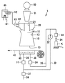
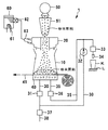
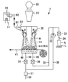
図1に示した飲料抽出装置1は、機器筐体Bの内部に設けられるもので、シリンダ10(抽出容器)およびフィルタブロック40を配設してある。
シリンダ10は上下両端面を開口した円筒形状を成し、その上端開口11と下端開口13との間のくびれ部12を鼓状に形成してあり、昇降手段(図示せず)によって上下動可能に支持され、上動した場合に、フィルタブロック40から離隔した位置に配置される一方、下動した場合にフイルタ41を介してフィルタブロック40に嵌合して下端開口13が閉塞される。
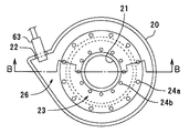
シリンダ10の上方には、ミル50からシュート51を介して供給されるコーヒー原料としての粉末原料をシリンダ10に投入する原料投入口21と、湯タンク60に貯留されタンクヒータ61で加熱(例えば、94℃)されている湯を湯バルブ62を介して湯ノズル63から供給する湯導入口22を設けた湯供給器20を上端開口11に嵌合させて装着している。
The
The
Above the
フィルタブロック40は、有底の円筒形状を成すもので、送出通路30およびエア供給通路35が接続してある。送出通路30は、フィルタブロック40から開閉バルブ31、抽出ポンプ32および注出バルブ33を介して注出ノズル34に至る流体通路であり、抽出ポンプ32が駆動している時にフィルタブロック40の液体を注出ノズル34に送出することが可能である。エア供給通路35は、フィルタブロック40にエアを供給するためのもので、フィルタブロック40からエアバルブ36を介して送出通路30における抽出ポンプ32と注出バルブ33との間に位置する部分に接続してある。
フィルタ41は、ロール状に巻回された紙製で帯状を成すフィルタ紙で、シリンダ10とフィルタブロック40との間へ順次繰り出され、コーヒー原料としての粉末原料と湯との混合体を負圧の下で濾過してコーヒー飲料とする。
The
The
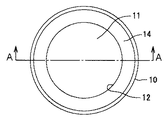
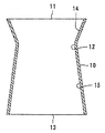
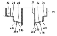
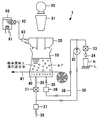
図3はシリンダ10の平面図、図4は図3のA−A部を矢印方向に見た断面側面図である。
シリンダ10は、円筒のくびれ部12からその端に向い内径を拡げて開放した上端開口11と下端開口13とを有している。
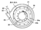
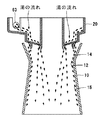
図5は湯供給器20の平面図、図6は図5のB−B部を矢印方向に見た断面側面図、図7は湯供給器20内の湯の流れを示す図、図8はシリンダ10の上端開口11に湯供給器14を嵌合させて装着した状態での湯の流れを示す図である。
湯供給器20は、原料投入口21の外周下方に延在して設けた、湯を環状の所定方向の流れにして導入するための内側方向に下降する傾斜したロート形状の傾斜面を形成した湯導入通路23と、湯を湯導入通路23の所定方向の流れに従って分散する態様で湯導入通路23の周方向に沿って複数穿設した2列の湯通路穴24a、24bと、内側方向に下降する湯導入通路下面23bの湯通路穴24aの内側に環状に形成したリブ片25aと、湯通路穴24bの内側に環状に形成したリブ片25bと、挿通した湯ノズル63が吐出した湯を湯導入通路23に導き入れる湯導入部26と、を有する。このように湯通路穴24a、24bとリブ片25a、25bを外周と内周との二重に設けている。また、リブ片25a、25b外側にはV溝を複数形成している。
FIG. 3 is a plan view of the
The
5 is a plan view of the
The hot
そして、湯ノズル63が湯を吐出すると、図7に示すように、湯導入部26に供給された湯は所定方向(図中矢印で示す方向)に流れ、図8に示すように、湯導入通路23に穿設した2列の湯通路穴24a、24bから流下する。この湯通路穴24bから流下した湯は穴から直接またはリブ片25aに形成しているV溝から流れ落ち、フィルタ41上に投入されたコーヒー原料としての粉末原料を満遍なく均一に「蒸らし湯」となって蒸らす。また、湯通路穴24aから流下した高温(例えば、94℃)の湯はシリンダ10の上端開口11とくびれ部12との間のシリンダ傾斜面14からシリンダ内壁面15に流れ落ち、付着しているコーヒー原料の原料滓をコーヒー油成分とともに流れ落とす。このように飲料抽出の都度シリンダ10に供給する高温の湯でシリンダ内壁面15に付着した原料滓をコーヒー油成分とともに流れ落とすので、そこに含まれる成分が変質するまで付着することがなくなり、変質した成分が抽出時に溶出してコーヒー飲料の香味や旨味を損ねるようなことがなくなるので、香味や旨味を十分に引き出した品質の高い飲料を抽出するのに適した飲料抽出装置を提供することができる。
When the
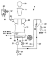
図9〜図12は、上述した飲料抽出装置の動作を説明するための模式図である。以下、図1、図7、図8、図9〜図12を適宜参照しながら、飲料抽出装置1の動作を説明する。
まず、商品選択ボタンDが押下されていない場合、飲料抽出装置1は図1に示すように、販売待機状態となっている。この販売待機状態においては、シリンダ10は、フィルタブロック40およびフィルタ41から離隔した状態にある。また、この販売待機状態においては、湯バルブ62が閉鎖した状態に保持されている一方、開閉バルブ31、注出バルブ33、エアバルブ36、開閉バルブ37がそれぞれ開放した状態に保持されている。湯タンク60では内部に貯留した湯をタンクヒータ61が所定の温度、例えば94℃に維持している。
FIGS. 9-12 is a schematic diagram for demonstrating operation | movement of the drink extraction apparatus mentioned above. Hereinafter, the operation of the
First, when the product selection button D is not pressed, the
上述した販売待機状態から利用者等によって硬貨が投入され、かつ任意の商品選択ボタンDが押下されると、抽出制御部(図示せず)から信号が出力されて昇降手段を駆動することにより、図9に示すように、フィルタ41を介してシリンダ10の下端開口13をフィルタブロック40に嵌合させて装着する。その後、ミル50を駆動することによってコーヒー豆を粉砕したコーヒー原料としての粉末原料を原料シュータ51から原料投入口21を介してシリンダ10の内部に投入する。
予め設定した量の粉末原料がシリンダ10に投入されると、抽出制御部は、開閉バルブ31、注出バルブ33、エアバルブ36をそれぞれ閉鎖した後、図10に示すように、湯バルブ62を開放して湯ノズル63から湯を吐出して供給する。そうすると、図7、図8に示すように、供給された湯は、湯導入部26、湯導入通路23を所定方向に流れ、湯通路穴24a、24bから流下する。湯通路穴24bから流下した湯はフィルタ41上に投入された粉末原料を満遍なく均一に蒸らすとともに、湯通路穴24aから流下した高温の湯がシリンダ10の上端開口11とくびれ部12との間のシリンダ傾斜面14からシリンダ内壁面15に流れ落ち、付着している粉末原料の原料滓をコーヒー油成分とともに流れ落とす。
When a coin is inserted by a user or the like from the above-described sales standby state and an arbitrary product selection button D is pressed, a signal is output from the extraction control unit (not shown) to drive the lifting means, As shown in FIG. 9, the
When a predetermined amount of powder raw material is charged into the
そして、供給した湯が予め設定した量に達すると、抽出制御部は、図11に示すように、湯バルブ62を閉鎖した後、開閉バルブ31および注出バルブ33を閉鎖した状態に保持する一方、エアバルブ36、開閉バルブ37を開放した状態で抽出ポンプ32を駆動し、通路38から送出通路30、エア供給通路35を通じてフィルタブロック40からシリンダ10の内部にエアを供給して、シリンダ10に貯留される粉末原料と湯との混合体の撹拌を行う。この結果、粉末原料から湯に香味や旨味が抽出され、シリンダ10の内部においてコーヒー飲料が生成されることになる。
しかる後、抽出制御部は、図12に示すように、エアバルブ36、開閉バルブ37を閉鎖してエアの供給を停止する一方、開閉バルブ31および注出バルブ33を開放して抽出ポンプ32を駆動する。この結果、シリンダ10の内部で生成されたコーヒー飲料がフィルタ41を透過して濾過され、送出通路30から注出ノズル34を通じて販売トレイLに載置されたカップKに注がれる。
When the supplied hot water reaches a preset amount, the extraction control unit holds the open /
Thereafter, as shown in FIG. 12, the extraction control unit closes the
予め設定した量のコーヒー飲料をカップKに供給すると抽出制御部は、昇降手段を駆動することによりシリンダ10を上動させ、一定量のフィルタ41を繰り出し、使用後のフィルタ41およびこれに付着する抽出滓を滓バケツ(図示せず)に収納させる。
以降、上述した飲料抽出動作を繰り返し実行すると、その都度シリンダ10に供給する高温の湯でシリンダ内壁面15に付着した原料滓をコーヒー油成分とともに流れ落とすことができるので、そこに含まれる成分が変質するまで付着することがなくなり、変質した成分が抽出時に溶出してコーヒー飲料の香味や旨味を損ねるようなことがなくなるので、香味や旨味を十分に引き出した品質の高い飲料を抽出するのに適した飲料抽出装置を提供することができる。
なお、上述した実施の形態では、挽き豆を粉末原料としたコーヒー原料からコーヒー飲料を抽出する装置を例示しているが、本発明はその他の粉末原料から飲料を抽出するものに適用することができる。
When a predetermined amount of coffee drink is supplied to the cup K, the extraction control unit drives the elevating means to move the
Thereafter, when the beverage extraction operation described above is repeatedly executed, the raw rice cake adhering to the cylinder
In addition, in embodiment mentioned above, although the apparatus which extracts a coffee drink from the coffee raw material which uses ground beans as a powder raw material is illustrated, this invention is applicable to what extracts a drink from other powder raw materials. it can.
1 飲料抽出装置
10 シリンダ
11 上端開口
12 くびれ部
13 下端開口
14 シリンダ傾斜面
15 シリンダ内壁面
20 湯供給器
21 原料投入口
22 湯導入口
23 湯導入通路
24a 湯通路穴
24b 湯通路穴
25a リブ片
25b リブ片
26 湯導入部
30 送出通路
31 開閉バルブ
32 抽出ポンプ
33 注出バルブ
34 注出ノズル
35 エア供給通路
36 エアバルブ
37 開閉バルブ
38 通路
40 フィルタブロック
41 フィルタ
50 ミル
51 原料シュータ
60 湯タンク
61 タンクヒータ
62 湯バルブ
63 湯ノズル
A カップ式飲料自動販売機
B 機器筐体
D 商品選択ボタン
E 商品販売口
K カップ
L 販売トレイ
DESCRIPTION OF
Claims (1)
前記抽出容器の上端開口に嵌合させて装着し、湯を流下させる多数の湯通路穴を円筒状に複数設けた湯供給器と、
を有し、前記粉末原料と湯との混合体から前記フィルタを通過させて前記フィルタブロックから濾過した飲料を抽出する飲料抽出装置であって、
前記湯供給器の円筒状に設けた内側の湯通路穴から流下させた湯で前記フィルタ上に投入された前記粉末原料を満遍なく均一に蒸らすとともに、
前記抽出容器は、その上端開口と下端開口との間をくびれ部とし、前記上端開口の内径を前記湯供給器の円筒状に設けた外側の湯通路穴から流下する湯の流下径より大とし、前記くびれ部の内径を前記湯供給器の円筒状に設けた外側の湯通路穴から流下する湯の流下径より小とし、
前記湯供給器の円筒状に設けた外側の湯通路穴から流下させた湯を前記抽出容器の内壁面を流下させ、付着している前記粉末原料の原料滓をコーヒー油成分とともに洗い流すようにしたことを特徴とする飲料抽出装置。 A cylindrical shape with both upper and lower end surfaces opened, and the lower end opening is fitted and closed through a filter block through a filter, and air is supplied to the powder raw material and hot water charged from the upper end opening and mixed with stirring. An extraction container for storing the body;
A hot water supplier that is fitted and fitted into the upper end opening of the extraction container, and has a plurality of hot water passage holes that allow the hot water to flow down in a cylindrical shape ,
A beverage extractor for extracting a filtered beverage from the filter block through the filter from a mixture of the powder raw material and hot water,
While uniformly steaming the powder raw material charged on the filter with hot water flowing down from the inner hot water passage hole provided in the cylindrical shape of the hot water supply device,
The extraction container has a constriction between the upper end opening and the lower end opening, and the inner diameter of the upper end opening is larger than the flow diameter of the hot water flowing down from the outer hot water passage hole provided in the cylindrical shape of the hot water supplier. The inner diameter of the constricted portion is smaller than the flowing-down diameter of the hot water flowing down from the outer hot water passage hole provided in the cylindrical shape of the hot water feeder,
The hot water that flowed down from the outer hot water passage hole provided in the cylindrical shape of the hot water feeder was caused to flow down the inner wall surface of the extraction container, and the adhering raw material powder of the powder raw material was washed away together with the coffee oil component . A beverage extraction device characterized by the above.
Priority Applications (1)
| Application Number | Priority Date | Filing Date | Title |
|---|---|---|---|
| JP2004002160A JP4155195B2 (en) | 2004-01-07 | 2004-01-07 | Beverage extractor |
Applications Claiming Priority (1)
| Application Number | Priority Date | Filing Date | Title |
|---|---|---|---|
| JP2004002160A JP4155195B2 (en) | 2004-01-07 | 2004-01-07 | Beverage extractor |
Publications (2)
| Publication Number | Publication Date |
|---|---|
| JP2005192801A JP2005192801A (en) | 2005-07-21 |
| JP4155195B2 true JP4155195B2 (en) | 2008-09-24 |
Family
ID=34817465
Family Applications (1)
| Application Number | Title | Priority Date | Filing Date |
|---|---|---|---|
| JP2004002160A Expired - Fee Related JP4155195B2 (en) | 2004-01-07 | 2004-01-07 | Beverage extractor |
Country Status (1)
| Country | Link |
|---|---|
| JP (1) | JP4155195B2 (en) |
Families Citing this family (5)
| Publication number | Priority date | Publication date | Assignee | Title |
|---|---|---|---|---|
| JP5055820B2 (en) * | 2006-04-24 | 2012-10-24 | 富士電機リテイルシステムズ株式会社 | Beverage extractor |
| MX2008014682A (en) * | 2006-05-19 | 2008-11-28 | Koninkl Philips Electronics Nv | Apparatus for preparing a beverage from an aqueous liquid and a fatty instant product, in particular baby milk. |
| JP6791685B2 (en) * | 2016-09-01 | 2020-11-25 | ツインバード工業株式会社 | coffee maker |
| NL2022152B1 (en) | 2017-12-07 | 2019-09-13 | Douwe Egberts Bv | A beverage fluid dispensing head and system |
| JP7443972B2 (en) | 2020-07-28 | 2024-03-06 | 富士電機株式会社 | extraction machine |
-
2004
- 2004-01-07 JP JP2004002160A patent/JP4155195B2/en not_active Expired - Fee Related
Also Published As
| Publication number | Publication date |
|---|---|
| JP2005192801A (en) | 2005-07-21 |
Similar Documents
| Publication | Publication Date | Title |
|---|---|---|
| US20200163487A1 (en) | Beverage producing apparatus | |
| KR101778722B1 (en) | Beverage preparation machines | |
| KR101974170B1 (en) | Coffee maker and method for operating same | |
| TWI454239B (en) | Beverage cartridge and system | |
| KR920001494B1 (en) | Automatic coffee vending machine being able to serve a straight coffee and a blended coffee selectively | |
| TWI623484B (en) | Beverage machine | |
| US9282849B2 (en) | Beverage production machines with restrictors | |
| JP2021502147A (en) | How to prepare food or beverage from a food or beverage dispenser and one or more containers | |
| JP6709988B2 (en) | Beverage supply device | |
| JP4155195B2 (en) | Beverage extractor | |
| US11622646B2 (en) | Beverage producing apparatus | |
| JP2010503591A (en) | Coffee and tea dispensing system | |
| JP4033064B2 (en) | Beverage extractor | |
| JP4238345B2 (en) | Beverage extractor | |
| JP2004159831A (en) | Beverage extraction device | |
| JP2005115419A (en) | Beverage brewer | |
| JP6993695B2 (en) | Coffee making equipment and control method | |
| JP3994935B2 (en) | Beverage extractor | |
| JP2007061189A (en) | Beverage extractor | |
| JP2006178572A (en) | Beverage brewer | |
| JPH0785362A (en) | Coffee maker for cup type automatic vending machine | |
| JP2007148895A (en) | Cup-type beverage vending machine | |
| JP2002367022A (en) | Coffee drink extracting device | |
| JP6776606B2 (en) | Cup vending machine | |
| JP2005078552A (en) | Beverage extracting device |
Legal Events
| Date | Code | Title | Description |
|---|---|---|---|
| A621 | Written request for application examination |
Free format text: JAPANESE INTERMEDIATE CODE: A621 Effective date: 20060516 |
|
| RD02 | Notification of acceptance of power of attorney |
Free format text: JAPANESE INTERMEDIATE CODE: A7422 Effective date: 20060703 |
|
| RD04 | Notification of resignation of power of attorney |
Free format text: JAPANESE INTERMEDIATE CODE: A7424 Effective date: 20060704 |
|
| A977 | Report on retrieval |
Free format text: JAPANESE INTERMEDIATE CODE: A971007 Effective date: 20071225 |
|
| A131 | Notification of reasons for refusal |
Free format text: JAPANESE INTERMEDIATE CODE: A131 Effective date: 20080115 |
|
| A521 | Written amendment |
Free format text: JAPANESE INTERMEDIATE CODE: A523 Effective date: 20080313 |
|
| TRDD | Decision of grant or rejection written | ||
| A01 | Written decision to grant a patent or to grant a registration (utility model) |
Free format text: JAPANESE INTERMEDIATE CODE: A01 Effective date: 20080617 |
|
| A01 | Written decision to grant a patent or to grant a registration (utility model) |
Free format text: JAPANESE INTERMEDIATE CODE: A01 |
|
| A61 | First payment of annual fees (during grant procedure) |
Free format text: JAPANESE INTERMEDIATE CODE: A61 Effective date: 20080630 |
|
| FPAY | Renewal fee payment (event date is renewal date of database) |
Free format text: PAYMENT UNTIL: 20110718 Year of fee payment: 3 |
|
| R150 | Certificate of patent or registration of utility model |
Free format text: JAPANESE INTERMEDIATE CODE: R150 |
|
| FPAY | Renewal fee payment (event date is renewal date of database) |
Free format text: PAYMENT UNTIL: 20110718 Year of fee payment: 3 |
|
| FPAY | Renewal fee payment (event date is renewal date of database) |
Free format text: PAYMENT UNTIL: 20120718 Year of fee payment: 4 |
|
| S531 | Written request for registration of change of domicile |
Free format text: JAPANESE INTERMEDIATE CODE: R313531 |
|
| FPAY | Renewal fee payment (event date is renewal date of database) |
Free format text: PAYMENT UNTIL: 20120718 Year of fee payment: 4 |
|
| R350 | Written notification of registration of transfer |
Free format text: JAPANESE INTERMEDIATE CODE: R350 |
|
| FPAY | Renewal fee payment (event date is renewal date of database) |
Free format text: PAYMENT UNTIL: 20120718 Year of fee payment: 4 |
|
| FPAY | Renewal fee payment (event date is renewal date of database) |
Free format text: PAYMENT UNTIL: 20130718 Year of fee payment: 5 |
|
| FPAY | Renewal fee payment (event date is renewal date of database) |
Free format text: PAYMENT UNTIL: 20130718 Year of fee payment: 5 |
|
| S111 | Request for change of ownership or part of ownership |
Free format text: JAPANESE INTERMEDIATE CODE: R313111 |
|
| FPAY | Renewal fee payment (event date is renewal date of database) |
Free format text: PAYMENT UNTIL: 20130718 Year of fee payment: 5 |
|
| R350 | Written notification of registration of transfer |
Free format text: JAPANESE INTERMEDIATE CODE: R350 |
|
| R250 | Receipt of annual fees |
Free format text: JAPANESE INTERMEDIATE CODE: R250 |
|
| R250 | Receipt of annual fees |
Free format text: JAPANESE INTERMEDIATE CODE: R250 |
|
| R250 | Receipt of annual fees |
Free format text: JAPANESE INTERMEDIATE CODE: R250 |
|
| R250 | Receipt of annual fees |
Free format text: JAPANESE INTERMEDIATE CODE: R250 |
|
| LAPS | Cancellation because of no payment of annual fees |