JP4154533B2 - Configuring signaling radio bearer information in the user equipment protocol stack - Google Patents
Configuring signaling radio bearer information in the user equipment protocol stack Download PDFInfo
- Publication number
- JP4154533B2 JP4154533B2 JP2005264498A JP2005264498A JP4154533B2 JP 4154533 B2 JP4154533 B2 JP 4154533B2 JP 2005264498 A JP2005264498 A JP 2005264498A JP 2005264498 A JP2005264498 A JP 2005264498A JP 4154533 B2 JP4154533 B2 JP 4154533B2
- Authority
- JP
- Japan
- Prior art keywords
- signaling radio
- radio bearer
- configuration
- signaling
- information element
- Prior art date
- Legal status (The legal status is an assumption and is not a legal conclusion. Google has not performed a legal analysis and makes no representation as to the accuracy of the status listed.)
- Active
Links
Images


Classifications
-
- H—ELECTRICITY
- H04—ELECTRIC COMMUNICATION TECHNIQUE
- H04W—WIRELESS COMMUNICATION NETWORKS
- H04W28/00—Network traffic management; Network resource management
- H04W28/16—Central resource management; Negotiation of resources or communication parameters, e.g. negotiating bandwidth or QoS [Quality of Service]
- H04W28/18—Negotiating wireless communication parameters
-
- H—ELECTRICITY
- H04—ELECTRIC COMMUNICATION TECHNIQUE
- H04W—WIRELESS COMMUNICATION NETWORKS
- H04W76/00—Connection management
- H04W76/10—Connection setup
- H04W76/11—Allocation or use of connection identifiers
-
- H—ELECTRICITY
- H04—ELECTRIC COMMUNICATION TECHNIQUE
- H04W—WIRELESS COMMUNICATION NETWORKS
- H04W80/00—Wireless network protocols or protocol adaptations to wireless operation
Abstract
Description
本特許文献に記載される技術は一般的に移動通信システムの分野に関連する。より特定的には、本特許文献は、ユーザー機器プロトコルスタックにおいてシグナリング無線ベアラ情報を設定(configure)するシステムおよび方法を記載する。 The technology described in this patent document is generally related to the field of mobile communication systems. More specifically, this patent document describes a system and method for configuring signaling radio bearer information in a user equipment protocol stack.
UMTS(Universal Mobile Telecommunications System)は第3世代公有地移動通信システムである。さまざまな標準化団体が、それぞれの適格性分野においてUMTSの標準を発表している。たとえば、3GPP(Third Generation Partnership Project)は、GSM(Global System for Mobile Communications)およびW−CDMA(Wideband Code Division Multiple Access)に基づくUMTSを発表し、3GPP2(Third Generation Partnership Project 2)は、CDMA2000(Code Division Multiple Access)に基づくUMTSの標準を発表している。標準文書3GPP TS 25.331はRRC(Radio Resource Control)プロトコル仕様を扱う。 UMTS (Universal Mobile Telecommunications System) is a third generation public land mobile communication system. Various standards bodies have published UMTS standards in their respective qualification areas. For example, 3GPP (Third Generation Partnership Project) is based on GSM (Global System for Mobile Communications) and W-CDMA (Wideband Code Division Multiple Access) based on UMTS. UMTS standard based on Division Multiple Access). The standard document 3GPP TS 25.331 deals with the RRC (Radio Resource Control) protocol specification.
ここに開示される教示にしたがって、シグナリング無線ベアラ情報を設定するシステムおよび方法が提供される。ユーザー機器とコアネットワークの間で情報を伝達する無線アクセスネットワークを含む無線ネットワークが用いられる。命令が受け取られ得て、事前選択した数のシグナリング無線ベアラのための設定情報を含むシグナリング無線ベアラ設定情報要素(IE)を生成する。それからシグナリング無線ベアラ設定IEが生成され得る一方、シグナリング無線ベアラ設定IEは要求された最少数のシグナリング無線ベアラのための設定情報を含むことを確実にする。ユーザー機器においてシグナリング無線ベアラの設定に使用するために、シグナリング無線ベアラ設定情報要素は、無線アクセスネットワークからユーザー機器に伝達され得る。 In accordance with the teachings disclosed herein, systems and methods for configuring signaling radio bearer information are provided. Wireless networks including wireless access networks that transfer information between the user equipment and the core network are used. An instruction may be received to generate a signaling radio bearer configuration information element (IE) that includes configuration information for a preselected number of signaling radio bearers. A signaling radio bearer setup IE may then be generated while ensuring that the signaling radio bearer setup IE contains setup information for the minimum number of requested signaling radio bearers. The signaling radio bearer configuration information element may be communicated from the radio access network to the user equipment for use in configuring the signaling radio bearer at the user equipment.
シグナリング無線ベアラ設定情報要素(IE)はユーザー機器によって受け取られ得て、事前に選択された数のシグナリング無線ベアラの設定情報を含む。ユーザー機器は、受信シグナリング無線ベアラ設定IEが要求された最小数のシグナリング無線ベアラの設定情報を含むか否かを決定し得る。受信シグナリング無線ベアラ設定IEが要求された最小数のシグナリング無線ベアラの設定情報を含まない場合、ユーザー機器は変則的な(anomalous)情報要素として受信シグナリング無線ベアラ設定IEを識別し得る。 A signaling radio bearer configuration information element (IE) may be received by the user equipment and includes configuration information for a preselected number of signaling radio bearers. The user equipment may determine whether the received signaling radio bearer setup IE includes the requested minimum number of signaling radio bearer setup information. If the received signaling radio bearer setup IE does not include the requested minimum number of signaling radio bearer setup information, the user equipment may identify the received signaling radio bearer setup IE as an anomalous information element.
本発明は、さらに以下の手段を提供する。 The present invention further provides the following means.
(項目1)
ユーザー機器とコアネットワークの間で情報を伝達する無線アクセスネットワークを含む無線ネットワークにおいて、該ユーザー機器においてシグナリング無線ベアラを設定する方法であって、該方法は、
事前に選択された数のシグナリング無線ベアラのための設定情報を含むシグナリング無線ベアラ設定情報要素(IE)を生成するための命令を受信することと、
該シグナリング無線ベアラ設定IEが、要求された最小数のシグナリング無線ベアラのための設定情報を含むことを確実にして、該シグナリング無線ベアラ設定IEを生成することと、
該ユーザー機器において該シグナリング無線ベアラを設定する際に用いるために、該シグナリング無線ベアラ設定情報要素を、該無線アクセスネットワークから該ユーザー機器に伝達することと
を包含する、方法。
(Item 1)
A method of setting up a signaling radio bearer in a user equipment in a wireless network including a radio access network that conveys information between the user equipment and a core network, the method comprising:
Receiving an instruction to generate a signaling radio bearer configuration information element (IE) including configuration information for a preselected number of signaling radio bearers;
Ensuring that the signaling radio bearer setup IE includes setup information for the requested minimum number of signaling radio bearers, and generating the signaling radio bearer setup IE;
Communicating the signaling radio bearer configuration information element from the radio access network to the user equipment for use in configuring the signaling radio bearer at the user equipment.
(項目2)
それぞれのシグナリング無線ベアラは2回以上設定されないことをさらに包含する、項目1に記載の方法。
(Item 2)
The method of
(項目3)
それぞれのシグナリング無線ベアラのための上記設定情報は、無線ベアラidentity情報要素 (IE)によって識別される、項目2に記載の方法。
(Item 3)
The method according to
(項目4)
上記生成するステップは、
それぞれの信号無線ベアラのための上記設定情報が無線ベアラidentity情報要素(IE)によって識別されること、または該設定情報は無線ベアラidentity IEを含まないことのいずれかを確実にすることをさらに包含する、項目1〜3のいずれか一項に記載の方法。
(Item 4)
The generating step is
It further includes ensuring that the configuration information for each signal radio bearer is identified by a radio bearer identity information element (IE) or that the configuration information does not include a radio bearer identity IE. The method according to any one of
(項目5)
上記シグナリング無線ベアラ設定IEは、Signaling Radio Bearer Information To Setup Listであって、これはRRC Connection Setup Messageにおいて上記ユーザー機器に伝送される、項目1〜4のいずれか一項に記載の方法。
(Item 5)
(項目6)
上記無線ネットワークは第3世代(3G)無線ネットワークである、項目1〜5のいずれかに従った方法。
(Item 6)
6. The method according to any of items 1-5, wherein the wireless network is a third generation (3G) wireless network.
(項目7)
上記無線ネットワークは、UTRAN(UMTS(Universal Mobile Telecommunications System)Terrestrial Radio Access Network)を含む、項目6に記載の方法。
(Item 7)
7. The method of
(項目8)
上記シグナリング無線ベアラ設定IEは、上記UTRANによって生成され、該UTRANから上記ユーザー機器に伝達される、項目7に記載の方法。
(Item 8)
8. The method of item 7, wherein the signaling radio bearer setup IE is generated by the UTRAN and communicated from the UTRAN to the user equipment.
(項目9)
上記要求された最小数のシグナリング無線ベアラは、RLC−UM(RLC(radio link control)unacknowledged mode)を用いる場合にDCCH(dedicated control channel)に伝達されるすべてのメッセージに用いられる第1のシグナリング無線ベアラ(SRB1)と、より高いレイヤシグナリングを搬送するRRC(radio resource control)メッセージを除くRLC認証モードを用いる場合に該DCCHに伝達されるすべてのメッセージに用いられる第2のシグナリング無線ベアラ(SRB2)と、より高いレイヤシグナリングを搬送するRRCに用いられてRLC認証モードにおける該DCCHに送られる第3のシグナリング無線ベアラ(SRB3)とを含む、項目1〜8のいずれか一項に記載の方法。
(Item 9)
The requested minimum number of signaling radio bearers is the first signaling radio used for all messages transmitted to the DCCH (Dedicated Control Channel) when using RLC-UM (radio link control (RLC)). Second signaling radio bearer (SRB2) used for all messages communicated to the DCCH when using RLC authentication mode except bearer (SRB1) and RRC (radio resource control) messages carrying higher layer signaling A third signaling radio bearer (SRB) used for RRC carrying higher layer signaling and sent to the DCCH in RLC authentication mode The method according to any one of
(項目10)
上記設定情報は、RLC Info情報要素およびRB Mapping情報要素を含む、項目8〜9のいずれか一項に記載の方法。
(Item 10)
The method according to any one of
(項目11)
ユーザー機器とコアネットワークの間で情報を伝達する無線アクセスネットワークを含む無線ネットワークにおいて、該ユーザー機器においてシグナリング無線ベアラを設定する方法であって、該方法は、
該ユーザー機器を用いてシグナリング無線ベアラ設定情報要素(IE)を受け取ることであって、該シグナリング無線ベアラ設定IEは事前に選択された数のシグナリング無線ベアラの設定情報を含む、ことと、
2つ以上のシグナリング無線ベアラの該設定情報は、同一のシグナリング無線ベアラidentity情報要素(IE)によって識別されるか否かを決定することと、
2つ以上のシグナリング無線ベアラの該設定情報が同一のシグナリング無線ベアラidentity情報要素(IE)によって識別される場合、該受信シグナリング無線ベアラ設定IEを変則的な情報要素として識別することと
を包含する方法。
(Item 11)
A method of setting up a signaling radio bearer in a user equipment in a wireless network including a radio access network that conveys information between the user equipment and a core network, the method comprising:
Receiving a signaling radio bearer configuration information element (IE) using the user equipment, the signaling radio bearer configuration IE including configuration information of a preselected number of signaling radio bearers;
Determining whether the configuration information of two or more signaling radio bearers is identified by the same signaling radio bearer identity information element (IE);
Identifying the received signaling radio bearer configuration IE as an irregular information element if the configuration information of two or more signaling radio bearers is identified by the same signaling radio bearer identity information element (IE). Method.
(項目12)
上記2つ以上のシグナリング無線ベアラの設定情報が同一のシグナリング無線ベアラidentity情報要素(IE)によって識別される場合、事前に選択された基準に基づく該シグナリング無線ベアラidentityIDの一例を選択することをさらに包含する、項目11に記載の方法。
(Item 12)
If the configuration information of the two or more signaling radio bearers is identified by the same signaling radio bearer identity information element (IE), further selecting an example of the signaling radio bearer identity ID based on a preselected
(項目13)
上記2つ以上のシグナリング無線ベアラの設定情報が同一のシグナリング無線ベアラidentity情報要素(IE)によって識別される場合、上記変則的な情報要素を識別し、新しいシグナリング無線ベアラ設定IEを要求する上記ユーザー機器からの報告を伝達する上記受信シグナリング無線ベアラIEを拒否することをさらに包含する、項目11に記載の方法。
(Item 13)
The user who identifies the anomalous information element and requests a new signaling radio bearer configuration IE if the configuration information of the two or more signaling radio bearers is identified by the same signaling radio bearer identity information element (IE) 12. A method according to item 11, further comprising rejecting the received signaling radio bearer IE carrying a report from a device.
(項目14)
上記受信シグナリング無線ベアラ設定IEが2つ以上のシグナリング無線ベアラの同一のidentity情報要素を含むために、該受信シグナリング無線ベアラ設定IEが変則的な情報要素として識別される場合、該受信シグナリング無線ベアラ設定IEを拒否し、アイドル状態に入ることをさらに包含する、項目11〜13のいずれか一項に記載の方法。
(Item 14)
If the received signaling radio bearer setup IE is identified as an anomalous information element because the received signaling radio bearer setup IE includes the same identity information element of two or more signaling radio bearers, the received signaling radio bearer 14. The method according to any one of items 11-13, further comprising rejecting the set IE and entering an idle state.
(項目15)
それぞれのシグナリング無線ベアラの上記設定情報がシグナリング無線ベアラidentity情報要素(IE)によって識別され、
上記受信シグナリング無線ベアラ設定IEが要求された最小数のシグナリング無線ベアラの設定情報を含むか否かを決定することと、
該受信シグナリング無線ベアラ設定IEが該要求された最小数のシグナリング無線ベアラの設定情報を含まない場合、該受信シグナリング無線ベアラ設定IEを変則的な情報要素として識別すること
をさらに包含する、項目11〜14のいずれか一項に記載の方法。
(Item 15)
The configuration information of each signaling radio bearer is identified by a signaling radio bearer identity information element (IE),
Determining whether the received signaling radio bearer configuration IE includes the requested minimum number of signaling radio bearer configuration information;
Item 11 further comprising identifying the received signaling radio bearer configuration IE as an anomalous information element if the received signaling radio bearer configuration IE does not include configuration information of the requested minimum number of signaling radio bearers. The method as described in any one of -14.
(項目16)
上記受信シグナリング無線ベアラ設定IEが上記要求された最小数のシグナリング無線ベアラの情報を含まないために、該受信シグナリング無線ベアラ設定IEが変則的な情報要素として識別される場合、デフォルト設定値を用いて含まれないシグナリング無線ベアラを設定することをさらに包含する、項目15に記載の方法。
(Item 16)
If the received signaling radio bearer configuration IE is identified as an irregular information element because the received signaling radio bearer configuration IE does not include information on the requested minimum number of signaling radio bearers, the default configuration value is used. 16. The method of item 15, further comprising configuring a signaling radio bearer not included.
(項目17)
上記受信シグナリング無線ベアラ設定IEが上記要求された最小数のシグナリング無線ベアラの設定情報を含まないために、該受信シグナリング無線ベアラ設定IEが変則的な情報要素として識別される場合、新しいシグナリング無線ベアラ設定IEを要求する上記ユーザー機器からの報告を伝達することをさらに包含する、項目15に記載の方法。
(Item 17)
If the received signaling radio bearer configuration IE is identified as an anomalous information element because the received signaling radio bearer configuration IE does not include the requested minimum number of signaling radio bearer configuration information, a new signaling radio bearer 16. The method of item 15, further comprising communicating a report from the user equipment requesting a configuration IE.
(項目18)
上記受信シグナリング無線ベアラ設定IEが上記要求された最小数のシグナリング無線ベアラの設定情報を含まないために、該受信シグナリング無線ベアラ設定IEが変則的な情報要素として識別される場合、該受信シグナリング無線ベアラ設定IEを無視し、アイドル状態に入ることをさらに包含する、項目15に記載の方法。
(Item 18)
If the received signaling radio bearer setup IE is identified as an irregular information element because the received signaling radio bearer setup IE does not include the requested minimum number of signaling radio bearer setup information, the received signaling radio bearer 16. The method of item 15, further comprising ignoring the bearer setting IE and entering an idle state.
(項目19)
それぞれのシグナリング無線ベアラの上記設定情報がシグナリング無線ベアラidentity情報要素(IE)によって識別され、
上記受信シグナリング無線ベアラ設定がそれぞれのシグナリング無線ベアラのシグナリング無線ベアラidentity情報要素(IE)を含むか否かを決定することと、
上記受信シグナリング無線ベアラ設定IEがそれぞれのシグナリング無線ベアラのシグナリング無線ベアラidentity情報要素(IE)を含まない場合、該受信シグナリング無線ベアラ設定IEを変則的な情報要素として識別することと
をさらに包含する、項目11〜18のいずれか一項に記載の方法。
(Item 19)
The configuration information of each signaling radio bearer is identified by a signaling radio bearer identity information element (IE),
Determining whether the received signaling radio bearer configuration includes a signaling radio bearer identity information element (IE) of each signaling radio bearer;
Further comprising identifying the received signaling radio bearer configuration IE as an irregular information element if the received signaling radio bearer configuration IE does not include the signaling radio bearer identity information element (IE) of each signaling radio bearer. The method according to any one of Items 11 to 18.
(項目20)
上記受信シグナリング無線ベアラ設定IEがそれぞれのシグナリング無線ベアラのシグナリング無線ベアラidentity IEを含まないために、該受信シグナリング無線ベアラ設定IEが変則的な情報要素として識別される場合、新しいシグナリング無線ベアラ設定IEを要求する上記ユーザー機器からの報告を伝達することをさらに包含する、項目19に記載の方法。
(Item 20)
If the received signaling radio bearer configuration IE is identified as an irregular information element because the received signaling radio bearer configuration IE does not include the signaling radio bearer identity IE of each signaling radio bearer, a new signaling radio
(項目21)
上記受信シグナリング無線ベアラ設定IEがそれぞれのシグナリング無線ベアラのシグナリング無線ベアラidentity IEを含まないために、該受信シグナリング無線ベアラ設定IEが変則的な情報要素として識別される場合、該受信シグナリング無線ベアラ設定IEを無視し、アイドル状態に入ることをさらに包含する、項目19に記載の方法。
(Item 21)
If the received signaling radio bearer configuration IE is identified as an irregular information element because the received signaling radio bearer configuration IE does not include the signaling radio bearer identity IE of each signaling radio bearer, the received signaling radio
(項目22)
上記受信シグナリング無線ベアラ設定IEがそれぞれのシグナリング無線ベアラのシグナリング無線ベアラidentity IEを含まないために、該受信シグナリング無線ベアラ設定IEが変則的な情報要素として識別される場合、それぞれの欠けているシグナリング無線ベアラ設定IEのデフォルト値を割り当てることをさらに包含する、項目19に記載の方法。
(Item 22)
If the received signaling radio bearer setup IE is identified as an anomalous information element because the received signaling radio bearer setup IE does not include the signaling radio bearer identity IE of each signaling radio bearer, each missing
(項目23)
上記デフォルト値は第1の不使用値から始まるシグナリング無線ベアラdentity IEのセットから選択される、項目22に記載の方法。
(Item 23)
23. A method according to item 22, wherein the default value is selected from a set of signaling radio bearer identities IE starting from a first unused value.
(項目24)
上記デフォルト値は、上記シグナリング無線ベアラが上記受信シグナリング無線ベアラ設定IEにリストアップされる順に基づいて選択される、項目22に記載の方法。
(Item 24)
23. The method of item 22, wherein the default value is selected based on the order in which the signaling radio bearers are listed in the received signaling radio bearer configuration IE.
(項目25)
上記シグナリング無線ベアラ設定IEはSignaling Radio Bearer Information To Setup Listであって、これはRRC Connection Setup Messageにおける上記ユーザー機器に伝達される、項目11〜24のいずれか一項に記載の方法。
(Item 25)
25. The method according to any one of items 11 to 24, wherein the signaling radio bearer configuration IE is a Signaling Radio Bearer Information To Setup List, which is communicated to the user equipment in an RRC Connection Setup Message.
(項目26)
上記無線ネットワークは、UTRAN(UMTS(Universal Mobile Telecommunications System)Terrestrial Radio Access Network)を含む、項目25に記載の方法。
(Item 26)
26. The method of item 25, wherein the wireless network includes UTRAN (UMTS (Universal Mobile Telecommunications System) Terrestrial Radio Access Network).
(項目27)
上記シグナリング無線ベアラ設定IEは上記UTRANによって生成され、該UTRANから上記ユーザー機器に伝達される、項目26に記載の方法。
(Item 27)
27. The method of item 26, wherein the signaling radio bearer setup IE is generated by the UTRAN and communicated from the UTRAN to the user equipment.
(項目28)
上記要求された最小数のシグナリング無線ベアラは、RLC−UM(RLC(radio link control)unacknowledgde mode)を用いる場合にDCCH(dedicated control channel)に伝達されるすべてのメッセージに用いられる第1のシグナリング無線ベアラ(SRB1)と、より高いレイヤシグナリングを搬送するRRC(radio resource control)メッセージを除くRLC認証モードを用いる場合に該DCCHに伝達されるすべてのメッセージに用いられる第2のシグナリング無線ベアラ(SRB2)と、より高いレイヤシグナリングを搬送するRRCに用いられてRLC認証モードにおける該DCCHに送られる第3のシグナリング無線ベアラ(SRB3)とを含む、項目11〜27のいずれか一項に記載の方法。
(Item 28)
The required minimum number of signaling radio bearers is the first signaling radio used for all messages transmitted to the DCCH (Dedicated Control Channel) when using RLC-UM (radio link control (RLC)). Second signaling radio bearer (SRB2) used for all messages communicated to the DCCH when using RLC authentication mode except bearer (SRB1) and RRC (radio resource control) messages carrying higher layer signaling A third signaling radio bearer (SRB) used for RRC carrying higher layer signaling and sent to the DCCH in RLC authentication mode The method according to any one of items 11 to 27, including 3).
(項目29)
上記設定情報は、RLC Info情報要素およびRB Mapping情報要素を含む、項目28に記載の方法。
(Item 29)
29. A method according to item 28, wherein the setting information includes an RLC Info information element and an RB Mapping information element.
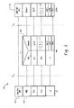
図面を参照すると、図1は、典型的な第3世代(3G)無線ネットワークを示すブロック図である。無線ネットワークは、UTRAN(UMTS(Universal Mobile Telecommunications System)Terrestrial Radio Access Network)100を含み、ATMバックボーン120を介して、コアネットワーク140に接続している。また、複数のユーザー機器110が図示され、これらは無線ネットワークを用いて無線で通信し得る。
Referring to the drawings, FIG. 1 is a block diagram illustrating a typical third generation (3G) wireless network. The wireless network includes UTRAN (UMTS (Universal Mobile Telecommunications System) Terrestrial Radio Access Network) 100 and is connected to the
UTRAN100は複数の基地局115(ノードB’と言及される)を含み、2つのみが図示されているが、Uuインタフェースで電波を用いてユーザー機器100と無線で通信する。特定のUTRAN100の性能に応じて、RNC130は、同一モードの複数のノードB’115かまたは多様なモードで動作する複数のノードBをサポートし得る。ATM(Asynchronous Transfer Mode)バックボーン120はさまざまなUTRAN成分を一つに結合し、UTRAN100をコアネットワーク140に結合する。
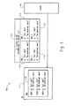
図2は、典型的なコアネットワーク140のブロック図である。ユーザー機器110もまた図示され、UTRAN100と共同で、ATMバックボーン120を介してコアネットワーク140と通信する。動作において、CS(circuit switched)パケットはTRAU(transcoder/rate adapter unit)210を介して送受信され得る。TRAU210は、移動通信交換局(MSC)210のためにUMTSスピーチパケットを標準パケットに変換し、公衆切り換えの公衆電話交換網(PSTN)226でスピーチを通信する。さらに、PS(packet switched)パケットは、SGSN(serving GPRS(General Packet Radio Service)support node)216と個人のIPバックボーン218とGGSN(Gateway GPRS Support Node)220と外部パケットネットワーク224を介して送受信され得る。
FIG. 2 is a block diagram of an
コアネットワーク140には、VLR(visitor location register)222およびHLR/AuC(home location register/authentication center)214もまた含まれる。VLR222は、関連するサービスエリア内での通話操作および他の機能のために必要なユーザー機器110情報を格納する。HLR/AuC214は、ユーザー機器110を識別するのに用いられる永久的記録を格納し、SGSNおよびVLRアドレスのような一時的記録もまた格納し得る。
The
典型的な3G無線ネットワークにおいて、3つのプロトコルのセットが用いられ、UTRANとユーザー機器の間でデータを伝達する。ユーザー機器とは、制御プレーン(plane)プロトコル、ユーザープレーンプロトコル、搬送ネットワークユーザープレーンプロトコルである。ユーザープレーンプロトコルは、アクセス層を介してユーザーデータを搬送することで、無線ベアラサービスを実行する。制御プレーンプロトコルは、無線アクセスベアラおよび、UTRANとユーザー機器の間の接続を制御するために用いられる。 In a typical 3G wireless network, three sets of protocols are used to carry data between UTRAN and user equipment. The user equipment is a control plane (plane) protocol, a user plane protocol, or a transport network user plane protocol. The user plane protocol carries out a radio bearer service by carrying user data through an access layer. The control plane protocol is used to control the radio access bearer and the connection between UTRAN and user equipment.
図3は、ユーザー機器とSGSNの間の典型的なUMTS制御プレーンアーキテクチャ300を図示する図である。制御プレーンアーキテクチャ300は、ユーザー機器制御プレーンプロトコルスタック310、RNC制御プレーンプロトコルスタック320、SGSN制御プレーンプロトコルスタック330を含む。特に、RRC層312は、ユーザー機器のための全体の無線リソース制御の責任がある。他の無線リソース制御機能の中で、RRC層312は、無線ベアラ(つまり、ユーザー機器とUTRANの間でデータを伝達するために提供されるサービス)の確立、再設定、解放の責任がある。RRCメッセージを伝達するために利用可能な無線ベアラは、「シグナリング無線ベアラ」と言及され、UTRANによって、Signaling Radio Bearer (RB) Information To Setup List (information element)IEに設定される。これは、UTRANからユーザー機器におけるRRCに伝達される。
FIG. 3 is a diagram illustrating an exemplary UMTS control plane architecture 300 between a user equipment and an SGSN. The control plane architecture 300 includes a user equipment control plane protocol stack 310, an RNC control
典型的3G無線ネットワークの詳細な記載は、図1〜図3に示されていて、国際電気通信連合によって公表されたIMT−2000(International Mobile Telecommunications−2000)標準、および3GPPTM(Third Generation Partnership Project)によって公表された3GPP標準文書に提供されていて、標準文書3GPP TS 23.101、3GPP TS 25.301、3GPP TS 25.331、3GPP TS 25.401を含み、これらはここに援用される。 A detailed description of a typical 3G wireless network is shown in FIGS. 1-3, and is published by the International Telecommunication Union, the IMT-2000 (International Mobile Telecommunications-2000) standard, and the 3GPP ™ (Third Generation Partnership Project). And 3GPP TS 23.101, 3GPP TS 25.301, 3GPP TS 25.331, 3GPP TS 25.401, which are incorporated herein by reference.
図4は、例示的な、Signaling RB Information To Setup List IE 430を示すブロック図400であって、ユーザー機器410のRRC層412にシグナリング無線ベアラを設定するためのものである。Signaling RB Information To Setup List 430は、UTRAN420から伝達され、それぞれのSRB(signaling radio bearer)が設定されるための情報要素432のセットを含む。Signaling RB Information To Setup List IE 430は、たとえば、それぞれの要素が次のASN.1構成を有するリストであり得る。
SRB−InformationSetup::=SEQUENCE{
rb−Identity RB−IdentityOPTIONAL,
rlc−InfoChoice RLC−InfoChoice,
rb−MappingInfo RB−MappingInfo}
標準文書3GPP TS 25.331にしたがって、使用するために3つのシグナリング無線ベアラ(SRB1−SRB3)が設定される必要があり、メッセージはDCCH(Dedicated Control Channel)に送られ、一つのシグナリング無線ベアラ(SRB4)は任意である。標準文書において、RLC−UM(RLC unacknowledged mode)が用いられる場合、SRB1が用いられ、すべてのメッセージがDCCHに送られる。RRCメッセージが高レイヤ(NAS)シグナリングを搬送する以外、RLC acknowledged modeを用いる場合、SRB2が用いられ、すべてのメッセージはDCCHに送られる。SRB3および随意的なSRB4がunacknowledged modeにおいてDCCHに送られる。
FIG. 4 is a block diagram 400 illustrating an exemplary Signaling RB Information To
SRB-InformationSetup :: = SEQUENCE {
rb-Identity RB-IdentityOPTIONAL,
rlc-InfoChoice RLC-InfoChoice,
rb-MappingInfo RB-MappingInfo}
According to the standard document 3GPP TS 25.331, three signaling radio bearers (SRB1-SRB3) need to be set up for use, and the message is sent to the DCCH (Dedicated Control Channel) and one signaling radio bearer ( SRB4) is optional. In the standard document, when RLC-UM (RLC unacknowledged mode) is used, SRB1 is used and all messages are sent to DCCH. Except for RRC messages carrying high layer (NAS) signaling, when using RLC acknowledged mode, SRB2 is used and all messages are sent on DCCH. SRB3 and optional SRB4 are sent on the DCCH in an unknown mode.
情報要素432のセットは、UTRAN420からSignaling RB Information To Setup List 430に伝達され、RRC412に用いられて、シグナリング無線ベアラを設定する。セット432内の情報要素は、RB Identity情報要素、RLC Info情報要素、RB Mapping Info 情報要素を含み得る。RB Identity情報要素が用いられ、情報要素432のそれぞれのセットによってどのシグナリング無線ベアラ(SRB1−SRB4)が設定されるかを識別する。RB Mapping InfoおよびRLC Info 情報要素が用いられて、RB Identity情報要素によって識別されたシグナリング無線ベアラを設定する。より特定的には、RB Mapping Info情報要素が用いられ、識別されたシグナリング無線ベアラのために多重化オプションを設定し、RLC Info情報要素が用いられ、識別されたシグナリング無線ベアラのために伝達および受信RLCエンティティを設定する。
The set of
Signaling RB Information To Setup List IE 430が、UTRAN420からのRRC Connection Setup Messageに含まれる場合、標準によって、IE 430はSRB1−SRB3それぞれおよび随意的にSRB4を設定する必要がある。つまり、SRB1−SRB3それぞれおよび随意的SRB4は、Signaling RB Information To Setup List IE 430によって識別され、設定されるべきである。しかしながら、図5および図6は、適切な設定情報を含まない非対応のSignaling RB Information To Setup List IE 510および610の2つの例を示す。
When the Signaling RB Information To
図5は、非対応のSignaling RB Information To Setup List IE 510の例を示し、これは同一のシグナリング無線ベアラ(SRB1)を2回、不適切に特定する。この例500において、非対応のSignaling RB Information To Setup IE 510は、4つの情報要素512、514、516、518のセットを含む。2つのセット512および514はRB Identity情報要素を含み、同一のシグナリング無線ベアラSRB1を特定する。他の2つの情報要素セット516および518はそれぞれSRB2およびSRB3を特定する。
FIG. 5 shows an example of a non-compliant Signaling RB Information To Setup List IE 510, which inappropriately identifies the same signaling radio bearer (SRB1) twice. In this example 500, the non-compliant Signaling RB Information To Setup IE 510 includes a set of four
図6は、非対応のSignaling RB Information To Setup List IE 600の別の例を示し、これは必要なシグナリング無線ベアラのための設定情報を含まない。上記のように、SRBリスト610がRRC Connectio設定Setup Messageに送られる場合、標準文書はシグナリング無線ベアラSRB1−SRB3が設定されることを要する。しかしながら、図示されるSignaling RB Information To Setup List IE 600は、SRB1、SRB3、SRB4のために設定情報612、614、615を含むのみである。Signaling RB Information To Setup List 610がRRC Connection Setup Message以外のメッセージに含まれる場合、標準はSRBが設定されることを要しない。
FIG. 6 shows another example of non-compliant Signaling RB Information To Setup List IE 600, which does not include configuration information for the required signaling radio bearers. As described above, when the SRB list 610 is sent to the RRC Connection Setup Setup Message, the standard document requires that the signaling radio bearers SRB1-SRB3 are set. However, the illustrated Signaling RB Information To Setup List IE 600 only includes
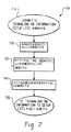
図7〜図9は、ユーザー機器プロトコルスタックにおいてシグナリング無線ベアラを設定するための3つの例示的方法700、800、900を示す。これらの例示的方法により、シグナリング無線ベアラ(SRB1〜SRB4)が標準文書にしたがって適切に設定されることを確実にするのに役立っている。図7は方法700であって、UTRAN420で実行され得て、図8および図9は方法800および900であって、ユーザー機器410によって実行され得る。
7-9 illustrate three
まず図7を説明すると、方法はステップ710から開始して、UTRANがユーザー機器410を設定するためにSignaling RB Information Setup Listを開始するように命令を受ける。ステップ720において、UTRAN420は設定情報を処理し、Signaling RB Information Setup Listに含まれる情報要素のセットが、図5に示されるように同一のシグナリング無線ベアラを特定しないことを確実にする。
Referring first to FIG. 7, the method begins at
ステップ730において、UTRAN420は、3G標準文書において不明瞭さにつながることになる、Signaling RB Information Setup Listから欠けている無線ベアラidentity IEがないことを確実にする。標準文書3GPP TS 25.331 version 3.10.0は、2つのセクション8.6.4.1および11.3を含み、これらは、無線ベアラidentity IEがSignaling RB Information Setup Listから欠けている状況に対処する。セクション8.6.4.1は、無線ベアラidentity IE(つまり、無数のSRB)が欠けている場合、UEは「1に等しいIE ’RB identity’のデフォルト値を、第1のIE ’Signaling RB information to setup’のために適用し、それぞれの発生につき、デフォルト値を1、増加する」ことを要求する。しかしながら、標準文書のセクション11.3は、IE「RB identity」がSignaling RB Information Setup Listから欠けている場合、最小の不使用値が用いられることを要する。一部の場合、セクション8.6.4.1および11.3の適用は異なる結果を達成し得る。ステップ730によってUTRANが、標準文書3GPP TS 25.331 version 3.10.0のセクション8.6.4.1と11.3の間の不明瞭さにつながることになるSignaling RB Information Setup Listの生成を防ぐ。これは、次のいずれかを確実にすることによって達成され得る:Signaling RB Information Setup Listにおけるそれぞれのシグナリング無線ベアラ設定のために無線ベアラidentity IE(つまり、IE「RB identity」)が含まれること、もしくは、無線ベアラidentity IEがSignaling RB Information Setup Listに含まれないことである。
In
ステップ740においてUTRAN420は、必要なシグナリング無線ベアラ(つまり、適用可能な3G標準によって必要とされるSRB)のためにSignaling RB Information To Setup Listに設定が含まれることを確実にする。UTRAN420は、たとえば、それぞれのSRB1〜SRB3がすでにユーザー機器410に設定されたか、または必要な設定がSignaling RB Information To Setup List IEに含まれるかを確実にする。Signaling RB Information To Setup List IEはそれからステップ750において、UTRAN420からユーザー機器410に伝達される。
In step 740,
図8を説明すると、方法800はステップ810から開始し、ユーザー機器410は、UTRAN 420からSignaling RB Information To Setup List IEを受ける。ステップ812において、ユーザー機器410は、受け取ったSignaling RB Information To Setup List IEが図5に示されるように同一のシグナリング無線ベアラ(SRB)を2回特定するかを決定する。そうであるならば、方法はステップ818において、受け取ったIEを、無効のまたは変則のSignaling RB Information To
Setup List IEとして識別する。さもなくば、2つのSRBがSignaling RB Information To Setup Listにおいて2回以上識別されない場合、方法はステップ814に進む。
Referring to FIG. 8, the
Identify as Setup List IE. Otherwise, if the two SRBs are not identified more than once in the Signaling RB Information To Setup List, the method proceeds to step 814.
ステップ814において、方法800は、図7を参照して上記されたように、標準文書3GPP TS 25.331 version 3.10.0のセクション8.6.4.1および11.3において不明瞭につながる、任意のシグナリング無線ベアラidentity IEがSignaling RB Information Setup Listから欠けているかを決定する。そうである場合、方法800は、ステップ818において、受け取ったIEを無効なまたは変則的なSignaling RB Information To Setup Listとして識別する。さもなくば、3G標準文書において不明瞭さにつながるシグナリング無線ベアラidentity IEが省略されていない場合、方法はステップ816に進む。
In
ステップ816において、方法800は、Signaling RB Information To Setup Listがまだユーザー機器410に設定されていないすべての必要なシグナリング無線ベアラ(つまり、適用可能な3G標準によって必要とされるSRB)のために設定情報を含むか否かを決定する。すべての必要なSRB設定情報が含まれていない場合、方法800はステップ818において、受け取ったIEを無効なまたは変則的なSignaling RB Information To Setup List IEとして識別する。さもなくば、すべての必要なSRB設定情報が受け取られたSignaling RB Information To Setup Listに含まれる場合、設定情報はステップ820においてシグナリング無線ベアラを設定するために用いられる。
In
受け取られたSignaling RB Information To Setup List IEが、ステップ818において無効であるまたは変則的であると識別される場合、方法800はステップ822において所定の手順にしたがってIEを処理する。たとえば、3G標準にしたがって、ユーザー機器は、無効なまたは変則的なIEをUTRANに報告し得て、新しいRRC Connection Setup Messageを受け取り得るかまたは、無効なまたは変則的なIEのUTRANを通知することなくアイドル状態に戻り得る。
If the received Signaling RB Information To Setup List IE is identified as invalid or anomalous at
図9を説明すると、別の例示的方法900がステップ910から開始し、Signaling RB Information To Setup Listがユーザー機器410によって受け取られる。ステップ912において、ユーザー機器410は、受け取られたSignaling RB Information To Setup List IEが、図5に示されるように、同一のシグナリング無線ベアラ(SRB)を2回特定するか否かを決定する。2つのSRBがSignaling RB Information To Setup Listにおいて2回以上特定されない場合、方法はステップ914に進む。さもなくば、複数のSRBの発生がステップ912において識別される場合、方法はステップ920において、所定の基準を用いて変則的なIEを解決する。たとえば、SRBが2回含まれる場合、ステップ920においてユーザー機器410は、発生の一つ(たとえば、最初のまたは最後の発生)が使用される設定として定義し得て、すべての他の発生は無視される。複数のSRBを解決すると、方法はステップ914に進む。
Referring to FIG. 9, another
ステップ914において、方法900は、図7へ参照して上記されたように、標準文書3GPP TS 25.331、 version 3.10.0のセクション8.6.4.1および11.3において不明瞭さにつながるであろう任意のシグナリング無線ベアラidentity IEがSignaling RB Information Setup Listから欠けているか否かを決定する。そうでない場合、方法はステップ916へ進む。しかしながら、3G標準文書において不明瞭さにつながる1つ以上のシグナリング無線ベアラidentity IEが省略されている場合、方法900はステップ922において所定の基準を用いて変則的なIEを解決する。たとえば、所定の基準922は、UEに命令し得て、標準文書3GPP TS 25.331、 version 3.10.0のセクション8.6.4.1またはセクション11.3のいずれかにおいて示されるデフォルトを用いて、1つ以上の欠けているSRB identity IEを解決する。
In step 914,
ステップ916において、方法900は、Signaling RB Information To Setup Listが、ユーザー機器410においてすでに設定されたすべての必要なシグナリング無線ベアラ(つまり、適応可能な3G標準によって要求されるSRB)のための設定情報を含むか否かを決定する。すべての必要なSRB設定情報が含まれる場合、方法900はステップ918に進み、シグナリング無線ベアラを設定する。さもなくば、1つ以上の必要なSRBのための設定情報が含まれない場合、方法はステップ214において、1つ以上のSRBのためのデフォルト設定値を選択することによって変則的なIEを解決する。ステップ924において欠けている設定エラーを解決すると、方法900はステップ918に進み、シグナリング無線ベアラを設定する。
In step 916, the
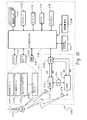
図10は、上記のユーザー機器として用いられ得る例示的移動通信装置2100を示すブロック図である。モバイル装置2100は、処理システム2138、通信システム2111、短距離通信サブシステム2140、メモリサブシステム2124および2126、さまざまな他の装置サブシステムおよび/またはソフトウエアモジュール2142を含む。モバイル装置2100はまたユーザーインタフェースを含み、これは、ディスプレイ2122、シリアルポート2130、キーボード2132、スピーカー2134、マイクロフォン2136、1つ以上の補助的入力/出力装置2128、および/または他のユーザーインタフェース装置を含み得る。
FIG. 10 is a block diagram illustrating an exemplary mobile communication device 2100 that may be used as the user equipment described above. Mobile device 2100 includes a
処理サブシステム2138は、モバイル装置2100の全体の動作を制御する。処理サブシステム2138によって実行されるオペレーティングシステムソフトウエアは、フラッシュメモリ2124のような固定ストアに格納され得るが、読み出し専用記憶装置(ROM)または同様の記憶装置要素のようなメモリサブシステムにおける他のタイプのメモリ装置にもまた格納され得る。さらに、システムソフトウエアまたは特定の装置アプリケーションまたはその部分は、RAM(random access memory)2126のような揮発性装置に一時的にロードされ得る。モバイル装置2100によって受け取られる通信信号はまたRAM2126に格納され得る。
The
処理サブシステム2138は、そのオペレーティングシステム機能に加えて、装置2100におけるソフトウエアアプリケーション2124の実行を可能にする。データおよび音声通信のような基本的な装置動作を制御するアプリケーションの所定のセットは、製造中に装置2100にインストールされ得る。さらに、電子メッセージ通信アプリケーションを含むPIM(personal information manager)アプリケーションは装置にインストールされ得る。PIMは、たとえば、eメール、カレンダー行事、音声メール、予約、タスク項目のようなデータ項目を整理し、管理するのに実施可能であり得る。PIMアプリケーションはまた、無線ネットワーク2119を介してデータ項目を送受信するのに実施可能であり得る。
データおよび音声通信を含む通信機能は、通信サブシステム2111とおそらくは短距離通信サブシステム2140を介して実行される。通信サブシステム2111は受信器2112と送信器2114と1つ以上のアンテナ2116および2118を含む。さらに、通信サブシステム2111はまた、DSP(digital signal processor)2120のような処理モジュールまたは他の処理装置とLO(local oscillator)2113を含む。通信サブシステム2111の特定の設計および実行は、モバイル装置2100が動作するように意図される通信ネットワークに依存している。たとえば、モバイル装置2100は、Mobitex(登録商標)移動通信システム、DataTAC(登録商標)移動通信システム、GSMネットワーク、GPRSネットワーク、UMTSネットワーク、および/またはEDGEネットワーク内で動作するように指定された通信サブシステム2111を含み得る。
Communication functions, including data and voice communication, are performed via communication subsystem 2111 and possibly short-range communication subsystem 2140. The communication subsystem 2111 includes a
ネットワークアクセス要求は、通信システムのタイプによって変わる。たとえば、MobitexおよびDataTACにおいて、モバイル装置は、それぞれの装置に関連する固有のpersonal identification numberすなわちPINを用いてネットワーク上に登録される。しかしながら、UMTSおよびGSM/GPRSネットワークにおいて、ネットワークアクセスは加入者または装置のユーザーに関連する。それゆえ、GPRS装置は、一般的にSIMカードと言及されるsubscriber identity moduleを要求し、GSM/GPRSネットワークで動作する。 The network access request varies depending on the type of communication system. For example, in Mobitex and DataTAC, mobile devices are registered on the network using a unique personal identification number or PIN associated with each device. However, in UMTS and GSM / GPRS networks, network access is associated with subscribers or device users. Therefore, GPRS devices require a subscriber identity module, commonly referred to as a SIM card, and operate in a GSM / GPRS network.
要求されたネットワーク登録または起動手順が完了すると、モバイル装置2100は、通信ネットワーク2119で通信信号を送受信し得る。アンテナ2216によって通信ネットワーク2119から受け取られた信号は受信器2112にルートされ、この受信器は信号増幅、周波数ダウン変換、フィルタリング、チャンネル選択などを提供し、また、アナログ‐デジタル変換をも提供し得る。受信信号のアナログ−デジタル変換によって、DSPは復調およびデコードのようなより複雑な通信機能を実行することができる。同様に、ネットワーク2119に伝達される信号は、DSP2120によって処理され(たとえば、変調され、符号化される)、それから送信器2114に提供される。これは、アンテナ2118を介して、デジタル‐アナログ変換、周波数アップ変換、フィルタリング、増幅、通信ネットワーク2119への伝達(または複数のネットワーク)のためである。
Upon completion of the requested network registration or activation procedure, mobile device 2100 may send and receive communication signals over communication network 2119. Signals received from communication network 2119 by antenna 2216 are routed to
処理通信信号に加えて、DSP2120は受信器2112および送信器2114の制御を提供する。たとえば、受信器2112および送信器2114において通信信号に適用されるゲインは、DSP2120において実行された自動ゲイン制御アルゴリズムを介して適応的に制御され得る。
In addition to the processing communication signals, the
データ通信モードにおいて、テキスト・メッセージまたはウェブページダウンロードのような受信信号は、通信サブシステム2111および処理装置2138への入力によって処理される。ディスプレイ2122への出力または代替的に一部の他の補助的I/O装置2128への出力のために、受信信号は処理装置2138によってさらに処理される。装置ユーザーはまた、キーボード2132および/または、タッチパッドまたはロッカースイッチまたはスライドロータリまたは一部の他のタイプの入力装置のような一部の他の補助的I/O装置2128を用いて、eメールメッセージのようなデータ項目を構成し得る。構成されたデータ項目はそれから通信サブシステム2111を介して通信ネットワーク2119へ伝達され得る。
In the data communication mode, received signals such as text messages or web page downloads are processed by inputs to the communication subsystem 2111 and the
音声通信モードにおいて、装置の全体の動作は、受信信号がスピーカー2134へ出力され、伝達のための信号がマイクロフォン2136によって生成されるという点を除いて、実質的にデータ通信モードに類似である。音声メッセージ録音システムのような代替の音声またはオーディオI/Oサブシステムもまた装置2100において実行され得る。さらに、ディスプレイ2122もまた音声通信モードにおいて利用され得て、たとえば、発呼者の識別、音声通信の時間、他の音声関連情報を表示する。
In the voice communication mode, the overall operation of the device is substantially similar to the data communication mode except that the received signal is output to the speaker 2134 and a signal for transmission is generated by the microphone 2136. Alternative voice or audio I / O subsystems such as a voice message recording system may also be implemented in device 2100. In addition, the
短距離通信サブシステム2140によって、移動機器2100と、必ずしも類似の装置である必要がない他の近似のシステムまたは装置との間の通信が可能になる。たとえば、短距離通信サブシステム2140は、赤外線装置および関連する回路と成分、すなわちBluetooth(登録商標)通信モジュールを含み得て、同様に使用可能なシステムおよび装置を通信に提供する。 The short-range communication subsystem 2140 enables communication between the mobile device 2100 and other similar systems or devices that are not necessarily similar devices. For example, the short-range communication subsystem 2140 may include an infrared device and associated circuitry and components, i.e., a Bluetooth® communication module, to provide similarly usable systems and devices for communication.
この記載は実施例を用いて、最良の形態モードを含む本発明を開示し、また当業者が本発明を作り、用いることができるようになる。本発明の特許の範囲は、当業者に起こる他の実施例を含み得る。 This description uses examples to disclose the invention, including the best mode, and also to enable any person skilled in the art to make and use the invention. The patentable scope of the invention may include other examples that occur to those skilled in the art.
ここに記載される教示にしたがって、ユーザー機器プロトコルスタックにおいてシグナリング無線ベアラを設定するシステムおよび方法が提供される。ユーザー機器とコアネットワークとの間で情報を伝達する無線アクセスネットワークを含む無線ネットワークが用いられ得る。命令が受け取られ得て、事前選択した数のシグナリング無線ベアラのための設定情報を含むシグナリング無線ベアラ設定情報要素(IE)を生成する。シグナリング無線ベアラ設定IEはそれから生成され得る一方、シグナリング無線ベアラ設定IEは要求されたシグナリング無線ベアラの最少数のための設定情報を含むことを確実にする。ユーザー機器においてシグナリング無線ベアラの設定に使用するために、シグナリング無線ベアラ設定情報要素は、無線アクセスネットワークからユーザー機器に伝達され得る。 In accordance with the teachings described herein, systems and methods for setting up a signaling radio bearer in a user equipment protocol stack are provided. A wireless network may be used including a wireless access network that communicates information between the user equipment and the core network. An instruction may be received to generate a signaling radio bearer configuration information element (IE) that includes configuration information for a preselected number of signaling radio bearers. The signaling radio bearer setup IE can then be generated, while the signaling radio bearer setup IE ensures that it contains setup information for the minimum number of requested signaling radio bearers. The signaling radio bearer configuration information element may be communicated from the radio access network to the user equipment for use in configuring the signaling radio bearer at the user equipment.
Claims (29)
事前に選択された数のシグナリング無線ベアラのための設定情報を含むシグナリング無線ベアラ設定情報要素(IE)を生成するための命令を受信することと、
該シグナリング無線ベアラ設定IEが、要求された最小数のシグナリング無線ベアラのための設定情報を含むことを確実にして、該シグナリング無線ベアラ設定IEを生成することと、
該ユーザー機器において該シグナリング無線ベアラを設定する際に用いるために、該シグナリング無線ベアラ設定情報要素を、該無線アクセスネットワークから該ユーザー機器に伝達することと
を包含する、方法。 A method of setting up a signaling radio bearer in a user equipment in a wireless network including a radio access network that conveys information between the user equipment and a core network, the method comprising:
Receiving an instruction to generate a signaling radio bearer configuration information element (IE) including configuration information for a preselected number of signaling radio bearers;
Ensuring that the signaling radio bearer setup IE includes setup information for the requested minimum number of signaling radio bearers, and generating the signaling radio bearer setup IE;
Communicating the signaling radio bearer configuration information element from the radio access network to the user equipment for use in configuring the signaling radio bearer at the user equipment.
それぞれの信号無線ベアラのための前記設定情報が無線ベアラidentity情報要素(IE)によって識別されること、または該設定情報は無線ベアラidentity IEを含まないことのいずれかを確実にすることをさらに包含する、請求項1〜3のいずれか一項に記載の方法。 The generating step includes
Further comprising ensuring that the configuration information for each signal radio bearer is identified by a radio bearer identity information element (IE) or that the configuration information does not include a radio bearer identity IE. The method according to any one of claims 1 to 3.
該ユーザー機器を用いてシグナリング無線ベアラ設定情報要素(IE)を受け取ることであって、該シグナリング無線ベアラ設定IEは事前に選択された数のシグナリング無線ベアラの設定情報を含む、ことと、
2つ以上のシグナリング無線ベアラの該設定情報は、同一のシグナリング無線ベアラidentity情報要素(IE)によって識別されるか否かを決定することと、
2つ以上のシグナリング無線ベアラの該設定情報が同一のシグナリング無線ベアラidentity情報要素(IE)によって識別される場合、該受信シグナリング無線ベアラ設定IEを変則的な情報要素として識別することと
を包含する方法。 A method of setting up a signaling radio bearer in a user equipment in a wireless network including a radio access network that conveys information between the user equipment and a core network, the method comprising:
Receiving a signaling radio bearer configuration information element (IE) using the user equipment, the signaling radio bearer configuration IE including configuration information of a preselected number of signaling radio bearers;
Determining whether the configuration information of two or more signaling radio bearers is identified by the same signaling radio bearer identity information element (IE);
Identifying the received signaling radio bearer configuration IE as an irregular information element if the configuration information of two or more signaling radio bearers is identified by the same signaling radio bearer identity information element (IE). Method.
前記受信シグナリング無線ベアラ設定IEが要求された最小数のシグナリング無線ベアラの設定情報を含むか否かを決定することと、
該受信シグナリング無線ベアラ設定IEが該要求された最小数のシグナリング無線ベアラの設定情報を含まない場合、該受信シグナリング無線ベアラ設定IEを変則的な情報要素として識別すること
をさらに包含する、請求項11〜14のいずれか一項に記載の方法。 The configuration information of each signaling radio bearer is identified by a signaling radio bearer identity information element (IE);
Determining whether the received signaling radio bearer configuration IE includes configuration information of a requested minimum number of signaling radio bearers;
And further comprising: identifying the received signaling radio bearer configuration IE as an anomalous information element if the received signaling radio bearer configuration IE does not include configuration information of the requested minimum number of signaling radio bearers. The method as described in any one of 11-14.
前記受信シグナリング無線ベアラ設定がそれぞれのシグナリング無線ベアラのシグナリング無線ベアラidentity情報要素(IE)を含むか否かを決定することと、
前記受信シグナリング無線ベアラ設定IEがそれぞれのシグナリング無線ベアラのシグナリング無線ベアラidentity情報要素(IE)を含まない場合、該受信シグナリング無線ベアラ設定IEを変則的な情報要素として識別することと
をさらに包含する、請求項11〜18のいずれか一項に記載の方法。 The configuration information of each signaling radio bearer is identified by a signaling radio bearer identity information element (IE);
Determining whether the received signaling radio bearer configuration includes a signaling radio bearer identity information element (IE) of each signaling radio bearer;
Further comprising identifying the received signaling radio bearer configuration IE as an irregular information element if the received signaling radio bearer configuration IE does not include a signaling radio bearer identity information element (IE) of each signaling radio bearer. The method according to any one of claims 11 to 18.
Applications Claiming Priority (1)
| Application Number | Priority Date | Filing Date | Title |
|---|---|---|---|
| EP04021719A EP1635591B1 (en) | 2004-09-13 | 2004-09-13 | Configuring signaling radio bearer information in a user equipment protocol stack |
Publications (2)
| Publication Number | Publication Date |
|---|---|
| JP2006121668A JP2006121668A (en) | 2006-05-11 |
| JP4154533B2 true JP4154533B2 (en) | 2008-09-24 |
Family
ID=34926520
Family Applications (1)
| Application Number | Title | Priority Date | Filing Date |
|---|---|---|---|
| JP2005264498A Active JP4154533B2 (en) | 2004-09-13 | 2005-09-12 | Configuring signaling radio bearer information in the user equipment protocol stack |
Country Status (9)
| Country | Link |
|---|---|
| EP (1) | EP1635591B1 (en) |
| JP (1) | JP4154533B2 (en) |
| CN (1) | CN100512493C (en) |
| AT (1) | ATE377337T1 (en) |
| CA (1) | CA2519091C (en) |
| DE (1) | DE602004009795T2 (en) |
| ES (1) | ES2295748T3 (en) |
| HK (1) | HK1091682A1 (en) |
| SG (1) | SG121130A1 (en) |
Families Citing this family (2)
| Publication number | Priority date | Publication date | Assignee | Title |
|---|---|---|---|---|
| WO2007107032A1 (en) * | 2006-03-15 | 2007-09-27 | Zte Corporation | A terminal radio bearer resource management method |
| CN111309827A (en) * | 2020-03-23 | 2020-06-19 | 平安医疗健康管理股份有限公司 | Knowledge graph construction method and device, computer system and readable storage medium |
Family Cites Families (2)
| Publication number | Priority date | Publication date | Assignee | Title |
|---|---|---|---|---|
| DE4321776C1 (en) * | 1993-06-30 | 1994-12-08 | Siemens Ag | Method for forming and analyzing information element-oriented signaling messages in communication devices |
| US20040180675A1 (en) * | 2002-11-06 | 2004-09-16 | Samsung Electronics Co., Ltd. | Method for transmitting and receiving control messages in a mobile communication system providing MBMS service |
-
2004
- 2004-09-13 EP EP04021719A patent/EP1635591B1/en active Active
- 2004-09-13 ES ES04021719T patent/ES2295748T3/en active Active
- 2004-09-13 DE DE602004009795T patent/DE602004009795T2/en active Active
- 2004-09-13 AT AT04021719T patent/ATE377337T1/en not_active IP Right Cessation
-
2005
- 2005-09-12 SG SG200505896A patent/SG121130A1/en unknown
- 2005-09-12 JP JP2005264498A patent/JP4154533B2/en active Active
- 2005-09-13 CN CNB2005101132507A patent/CN100512493C/en active Active
- 2005-09-13 CA CA2519091A patent/CA2519091C/en active Active
-
2006
- 2006-07-18 HK HK06108043A patent/HK1091682A1/en unknown
Also Published As
| Publication number | Publication date |
|---|---|
| HK1091682A1 (en) | 2007-01-26 |
| ES2295748T3 (en) | 2008-04-16 |
| SG121130A1 (en) | 2006-04-26 |
| DE602004009795T2 (en) | 2008-08-28 |
| EP1635591A1 (en) | 2006-03-15 |
| CA2519091C (en) | 2010-03-30 |
| EP1635591B1 (en) | 2007-10-31 |
| DE602004009795D1 (en) | 2007-12-13 |
| ATE377337T1 (en) | 2007-11-15 |
| CN100512493C (en) | 2009-07-08 |
| CN1802023A (en) | 2006-07-12 |
| CA2519091A1 (en) | 2006-03-13 |
| JP2006121668A (en) | 2006-05-11 |
Similar Documents
| Publication | Publication Date | Title |
|---|---|---|
| US8340042B2 (en) | Configuring signaling radio bearer information in a user equipment protocol stack | |
| US8358649B2 (en) | Methods for handling packet-switched data transmissions by mobile station with subscriber identity cards and systems utilizing the same | |
| JP4334802B2 (en) | Techniques for call setup in the technical field of Internet protocol mobile communication networks | |
| TWI416979B (en) | Method for handling data transmission by a mobile station and system for handling data transmission | |
| KR101116459B1 (en) | System and method for resolving contention among applications requiring data connections between a mobile communications device and a wireless network | |
| US8078144B2 (en) | Apparatus and method for applying ciphering in universal mobile telecommunications system | |
| US20040224698A1 (en) | Apparatus and method for establishing feedback in a broadcast or multicast service | |
| US20130010758A1 (en) | System and method for determining that a maximum number of ip sessions have been established | |
| Sanchez et al. | UMTS | |
| KR101040128B1 (en) | Customization of data session retry mechanism in a wireless packet data service network | |
| TW200303146A (en) | Method and system for GSM mobile station roaming to IS-41 | |
| EP2403281A1 (en) | Apparatuses and methods for packet handling for emergency bearer services | |
| JP4154533B2 (en) | Configuring signaling radio bearer information in the user equipment protocol stack | |
| JP4526913B2 (en) | Signal transport via bearer network for low latency services | |
| US8325698B2 (en) | Generating a public long code mask in a mobile communications system | |
| KR20070009454A (en) | Wireless communication system and method of implementing an evolved system attachment procedure | |
| KR100742169B1 (en) | Methods and apparatus for the communication between a wireless local area network and a mobile station | |
| JP4559213B2 (en) | Method and apparatus for access network authentication | |
| US20050237990A1 (en) | Data transmission method and system | |
| JP4629075B2 (en) | System and method for determining that a maximum number of IP sessions has been established | |
| US20050283829A1 (en) | Connection method | |
| CA2524309C (en) | System and method for generating a public long code mask in a mobile communications system | |
| Ghosh et al. | Gsm, gprs and umts |
Legal Events
| Date | Code | Title | Description |
|---|---|---|---|
| A977 | Report on retrieval |
Free format text: JAPANESE INTERMEDIATE CODE: A971007 Effective date: 20080402 |
|
| TRDD | Decision of grant or rejection written | ||
| A01 | Written decision to grant a patent or to grant a registration (utility model) |
Free format text: JAPANESE INTERMEDIATE CODE: A01 Effective date: 20080526 |
|
| A01 | Written decision to grant a patent or to grant a registration (utility model) |
Free format text: JAPANESE INTERMEDIATE CODE: A01 |
|
| RD02 | Notification of acceptance of power of attorney |
Free format text: JAPANESE INTERMEDIATE CODE: A7422 Effective date: 20080623 |
|
| RD04 | Notification of resignation of power of attorney |
Free format text: JAPANESE INTERMEDIATE CODE: A7424 Effective date: 20080623 |
|
| A61 | First payment of annual fees (during grant procedure) |
Free format text: JAPANESE INTERMEDIATE CODE: A61 Effective date: 20080623 |
|
| FPAY | Renewal fee payment (event date is renewal date of database) |
Free format text: PAYMENT UNTIL: 20110718 Year of fee payment: 3 |
|
| R150 | Certificate of patent or registration of utility model |
Free format text: JAPANESE INTERMEDIATE CODE: R150 Ref document number: 4154533 Country of ref document: JP Free format text: JAPANESE INTERMEDIATE CODE: R150 |
|
| FPAY | Renewal fee payment (event date is renewal date of database) |
Free format text: PAYMENT UNTIL: 20110718 Year of fee payment: 3 |
|
| FPAY | Renewal fee payment (event date is renewal date of database) |
Free format text: PAYMENT UNTIL: 20120718 Year of fee payment: 4 |
|
| R250 | Receipt of annual fees |
Free format text: JAPANESE INTERMEDIATE CODE: R250 |
|
| FPAY | Renewal fee payment (event date is renewal date of database) |
Free format text: PAYMENT UNTIL: 20120718 Year of fee payment: 4 |
|
| FPAY | Renewal fee payment (event date is renewal date of database) |
Free format text: PAYMENT UNTIL: 20130718 Year of fee payment: 5 |
|
| R250 | Receipt of annual fees |
Free format text: JAPANESE INTERMEDIATE CODE: R250 |
|
| R250 | Receipt of annual fees |
Free format text: JAPANESE INTERMEDIATE CODE: R250 |
|
| R250 | Receipt of annual fees |
Free format text: JAPANESE INTERMEDIATE CODE: R250 |
|
| R250 | Receipt of annual fees |
Free format text: JAPANESE INTERMEDIATE CODE: R250 |
|
| R250 | Receipt of annual fees |
Free format text: JAPANESE INTERMEDIATE CODE: R250 |
|
| R250 | Receipt of annual fees |
Free format text: JAPANESE INTERMEDIATE CODE: R250 |
|
| R250 | Receipt of annual fees |
Free format text: JAPANESE INTERMEDIATE CODE: R250 |
|
| R250 | Receipt of annual fees |
Free format text: JAPANESE INTERMEDIATE CODE: R250 |
|
| R250 | Receipt of annual fees |
Free format text: JAPANESE INTERMEDIATE CODE: R250 |
|
| R250 | Receipt of annual fees |
Free format text: JAPANESE INTERMEDIATE CODE: R250 |
|
| S111 | Request for change of ownership or part of ownership |
Free format text: JAPANESE INTERMEDIATE CODE: R313113 |
|
| R350 | Written notification of registration of transfer |
Free format text: JAPANESE INTERMEDIATE CODE: R350 |
|
| R250 | Receipt of annual fees |
Free format text: JAPANESE INTERMEDIATE CODE: R250 |
|
| R250 | Receipt of annual fees |
Free format text: JAPANESE INTERMEDIATE CODE: R250 |