JP4154174B2 - Traffic volume measuring device, traffic volume measuring method, and traffic volume measuring program - Google Patents
Traffic volume measuring device, traffic volume measuring method, and traffic volume measuring program Download PDFInfo
- Publication number
- JP4154174B2 JP4154174B2 JP2002145388A JP2002145388A JP4154174B2 JP 4154174 B2 JP4154174 B2 JP 4154174B2 JP 2002145388 A JP2002145388 A JP 2002145388A JP 2002145388 A JP2002145388 A JP 2002145388A JP 4154174 B2 JP4154174 B2 JP 4154174B2
- Authority
- JP
- Japan
- Prior art keywords
- base station
- traffic volume
- measuring
- noise power
- power
- Prior art date
- Legal status (The legal status is an assumption and is not a legal conclusion. Google has not performed a legal analysis and makes no representation as to the accuracy of the status listed.)
- Expired - Fee Related
Links
- 238000000034 method Methods 0.000 title claims description 75
- 230000005540 biological transmission Effects 0.000 claims description 428
- 238000004364 calculation method Methods 0.000 claims description 85
- 238000005259 measurement Methods 0.000 claims description 61
- 238000004891 communication Methods 0.000 claims description 34
- 238000000691 measurement method Methods 0.000 claims description 6
- 230000006870 function Effects 0.000 description 31
- 238000004088 simulation Methods 0.000 description 28
- 238000010295 mobile communication Methods 0.000 description 17
- 238000010586 diagram Methods 0.000 description 12
- 238000013461 design Methods 0.000 description 9
- 238000013459 approach Methods 0.000 description 6
- 230000000694 effects Effects 0.000 description 5
- 238000012986 modification Methods 0.000 description 4
- 230000004048 modification Effects 0.000 description 4
- 230000008569 process Effects 0.000 description 4
- 238000005094 computer simulation Methods 0.000 description 2
- 230000008901 benefit Effects 0.000 description 1
- 230000008859 change Effects 0.000 description 1
- 238000007796 conventional method Methods 0.000 description 1
- 238000009792 diffusion process Methods 0.000 description 1
- 230000007480 spreading Effects 0.000 description 1
- 230000003442 weekly effect Effects 0.000 description 1
Images
Classifications
-
- H—ELECTRICITY
- H04—ELECTRIC COMMUNICATION TECHNIQUE
- H04W—WIRELESS COMMUNICATION NETWORKS
- H04W16/00—Network planning, e.g. coverage or traffic planning tools; Network deployment, e.g. resource partitioning or cells structures
- H04W16/22—Traffic simulation tools or models
-
- H—ELECTRICITY
- H04—ELECTRIC COMMUNICATION TECHNIQUE
- H04W—WIRELESS COMMUNICATION NETWORKS
- H04W16/00—Network planning, e.g. coverage or traffic planning tools; Network deployment, e.g. resource partitioning or cells structures
- H04W16/18—Network planning tools
Description
【0001】
【発明の属する技術分野】
本発明は、符号分割多元接続方式により移動局と無線回線を設定して通信を行う基地局におけるトラフィック量を測定するトラフィック量測定装置、トラフィック量測定方法、トラフィック量測定プログラム及びトラフィック量測定プログラムを記録した記録媒体に関する。
【0002】
【従来の技術】
現在普及している携帯電話のような移動通信システムでは、サービスエリア全体をセルと呼ばれる比較的小さな無線ゾーンに分割して、移動通信サービスを提供している。このような移動通信システムは、セルをカバーする複数の基地局と、これらの基地局との間に無線回線を設定して通信を行う移動局とから構成されている。この移動通信システムを構成する各基地局に設置する設備の規模は、その基地局がカバーするセルのトラフィック量に応じて異なる。よって、移動通信システムを設計するシステム設計者は、トラフィック量の需要を綿密に見積もって、基地局の設備設計を行う必要がある。
【0003】
従来、システム設計者は、基地局設置前においては、例えば、基地局を設置する地域の人口、商業地であるか住宅地であるかなどの地域の種類等に基づいて、各基地局におけるトラフィック量の需要の見積もりを行っていた。又、実際に基地局を設置し、移動通信サービスを開始した後においては、システム設計者は、どの程度のユーザが各基地局を利用しているか、即ち、各基地局における実際のトラフィック量を測定し、測定した実際のトラフィック量に基づいて、各基地局に設定されている設備の増設や規模の縮小を決定していた。
【0004】
例えば、基地局と移動局が無線回線を接続する多元接続方式として周波数分割多元接続方式(Frequency Division Multiple Access、FDMA)や、時分割多元接続方式(Time Division Multiple Access、TDMAという)を用いた移動通信システムでは、設定している無線回線数(チャネル数)を計数することによって、実際のトラフィック量を把握していた。
【0005】
一方、多元接続方式として符号分割多元接続方式(Code Division Multiple Access、以下「CDMA」という)を用いるいわゆる第3世代の移動通信システムにおいては、各基地局が、周辺の基地局における通信を干渉として観測するため、基地局におけるトラフィック量は、基地局が移動局との間に設定している無線回線数(チャネル数)から求められる、実際に基地局と接続している移動局数(以下「実際のユーザ数」という)と、周辺の基地局からの干渉量を、基地局が移動局との間に設定している無線回線数(チャネル数)、即ち、基地局と接続している移動局数に換算した値(以下「換算ユーザ数」という)との合計となる。
【0006】
即ち、CDMAを用いる場合、基地局におけるトラフィック量は、無線回線数から求められる実際のユーザ数だけでは定まらず、周辺の基地局における通信の状況に左右されてしまう。そこで、CDMAを用いる基地局では、上り回線では、基地局における干渉量がトラフィック量に対応した量であるとして、下り回線では、基地局における送信電力がトラフィック量に対応した量であるとして、新たな呼を受け付けるか否か等の判定をおこなっていた(特開平8−191481号、国際公開番号WO98/30057)。
【0007】
又、計算機シミュレーションにより、CDMAを用いた基地局の上り回線の干渉量を補正した値が、トラフィック量に相当する値であることの検証も行われている(石川、岩村、「W−CDMA方式上り回線における干渉電力分布と呼損率の測定方法」2000年電子情報通信学会総合大会、B−5−31,2000−03)。又、移動通信システムを電波伝搬を考慮して設計するために、計算機を用いて基地局や移動局の緒元や地形データ等に基づき電波伝搬を模擬し、サービスエリアの電波伝搬状況を評価する手法を用いることがある(藤井、朝倉、山崎、「移動通信におけるセル設計システム」、NTTDoCoMoテクニカルジャーナルVol.2,No.4,pp.28−34,1995−01や、大松澤、山下、「置局設計総合支援システム」、NTTDoCoMoテクニカルジャーナルVol.4,No.1,pp.28−31,1996−04)。この手法においては、ごく小さく分割された区域毎に、標高データや地形データ、トラフィック量等のデータを保持し、それらに基づき受信点における信号対雑音電力比(SNR)や、基地局毎のトラフィック量の計算等を行う。
【0008】
【発明が解決しようとする課題】
しかしながら、従来の上り回線では基地局における干渉量を、下り回線では基地局における送信電力を、それぞれトラフィック量に対応した量とする方法では、次のような問題点があった。干渉量や送信電力は、トラフィック量に対応し、干渉量や送信電力が増加すればトラフィック量も増加するものの、実際のユーザ数に正比例した値ではなく、トラフィック量そのものではなかった。そのため、干渉量や送信電力では、トラフィック量を正確に把握することができず、トラフィック量が増えることにより基地局にかかる負荷(以下「トラフィック負荷」という)の状況を適切に把握することができなかった。
【0009】
又、計算機シミュレーションにより、CDMAを用いた基地局の上り回線の干渉量を補正し、トラフィック量に相当する値を求める方法では、移動局当たりの受信電力を測定しなければならず、他にも、全体の限界容量を予め把握しておく必要がある等、実用上、把握することが困難なパラメータが多かった。そのため、この方法は、トラフィック量そのものを正確に把握することができず、簡単にトラフィック量を求めることができないため、実用化が困難であった。又、この方法では、下り回線についてはそのトラフィック量に相当する値を求めることができなかった。更に、サービスエリアの電波伝搬状況を評価する手法でも、基地局の正確なトラフィック量そのものを把握して、トラフィック負荷を評価することができず、又、種々のデータを保持する必要があり、簡単にトラフィック量を求めることができなかった。
【0010】
そこで、本発明は、CDMAを用いて通信を行う基地局におけるトラフィック量を正確に、かつ、簡単に求めることができ、基地局におけるトラフィック負荷を把握することができるトラフィック量測定装置、トラフィック量測定方法、トラフィック量測定プログラム及びトラフィック量測定プログラムを記録した記録媒体を提供することを目的とする。
【0011】
【課題を解決するための手段】
本発明に係るトラフィック量測定装置は、符号分割多元接続方式(CDMA)により移動局と無線回線を設定して通信を行う基地局におけるトラフィック量を測定するトラフィック量測定装置であって、トラフィック量を測定する際の基準となる基地局における基準雑音電力を設定する雑音電力設定手段と、基地局における雑音電力を測定する雑音電力測定手段と、設定した基準雑音電力及び測定した雑音電力に基づいて、トラフィック量を算出する算出手段とを備えることを特徴とする。
【0012】
ここで、トラフィック量とは、基地局が移動局との間に設定している無線回線数(チャネル数)、即ち、実際に基地局と接続している移動局数である実際のユーザ数と、周辺の基地局からの干渉量を、基地局が移動局との間に設定している無線回線数(チャネル数)、即ち、基地局と接続している移動局数に換算した換算ユーザ数との合計をいう。尚、トラフィック量は、実際のユーザ数と換算ユーザ数の合計そのものだけでなく、例えば、基地局が無線回線を設定し、接続可能な最大の移動局数(以下「限界容量」という)に対する実際のユーザ数と換算ユーザ数の合計の割合や、実際のユーザ数と換算ユーザ数の合計の基準値からの差、実際のユーザ数と換算ユーザ数の合計に正比例する値等、実際のユーザ数と換算ユーザ数の合計の状況を示すもの全てを含み、その表現方法は特に限定されない。又、雑音電力とは、基地局を構成し、移動局からの無線信号を受信する基地局受信装置自体が持っている熱雑音電力と、全移動局からの干渉雑音電力との総和をいい、いわゆる基地局における干渉量のことである。
【0013】
このような本発明にかかるトラフィック量測定装置によれば、雑音電力設定手段がトラフィック量を測定する際の基準となる基準雑音電力を設定し、雑音電力測定手段が、基地局における実際の雑音電力を測定する。そして、算出手段が、実際に測定した雑音電力だけでなく、基準となる基準雑音電力に基づいて、トラフィック量を算出する。そのため、トラフィック量測定装置は、基準雑音電力に対する実際の雑音電力の状況を求めることができ、基地局におけるトラフィック量を正確に求めることができる。よって、本発明にかかるトラフィック量測定装置によれば、CDMAを用いて通信を行う基地局の上り回線におけるトラフィック負荷の状況を適切に反映したトラフィック量を求めることができ、基地局の上り回線におけるトラフィック負荷の状況を適切に把握することができる。その結果、求めたトラフィック量を用いて、基地局の設備設計を正確に行うことができる。更に、トラフィック量測定装置は、基準雑音電力を設定し、実際の雑音電力を測定するだけで、簡単にトラフィック量を求めることができる。
【0014】
又、雑音電力設定手段は、基準雑音電力として、基地局におけるトラフィック量が0の場合のその基地局における雑音電力や、予め設定された時間の基地局における雑音電力、基地局におけるトラフィック量がその基地局において許容される上限値の場合の基地局における雑音電力等を設定することが好ましい。
【0015】
又、算出手段は、設定した基準雑音電力をN1、測定した雑音電力をN2として、
【数5】

【0016】
(1)式によれば、算出手段は、基地局における実際のユーザ数に正比例した正確なトラフィック量を求めることができる。よって、トラフィック量測定装置は、基地局の上り回線におけるトラフィック負荷の状況を適切に反映したトラフィック量を求めることができる。更に、算出手段は、(1)式のような簡単な式により、トラフィック量を求めることができる。
【0017】
又、雑音電力設定手段は、基準雑音電力を複数設定し、算出手段は、複数の基準雑音電力及び雑音電力に基づいて、トラフィック量を算出するようにしてもよい。これによれば、算出手段は、基準となる基準雑音電力を複数用いてトラフィック量を算出することができる。よって、トラフィック量測定装置は、複数の基準雑音電力に対する実際の雑音電力の状況を求めることができ、基地局におけるトラフィック量をより正確に求めることができる。よって、基地局の上り回線におけるトラフィック負荷の状況をより適切に反映したトラフィック量を求めることができる。
【0018】
又、複数の基準雑音電力を設定する場合、雑音電力設定手段は、基準雑音電力を2つ設定し、トラフィック量が0の場合の基地局における雑音電力、又は、予め設定された時間の基地局における雑音電力のいずれか一方を、基準雑音電力の一方として設定し、予め設定された時間の基地局における雑音電力、又は、トラフィック量が基地局において許容される上限値の場合の基地局における雑音電力のいずれか一方を、基準雑音電力の他方として設定することが好ましい。
【0019】
又、複数の基準雑音電力を設定する場合、雑音電力設定手段は、基準雑音電力を2つ設定し、算出手段は、設定した基準雑音電力の一方をN1、他方をN3、測定した雑音電力をN2として、
【数6】
【0020】
(2)式によれば、算出手段は、基地局における実際のユーザ数に正比例した正確なトラフィック量を求めることができる。よって、トラフィック量測定装置は、基地局の上り回線におけるトラフィック負荷の状況を適切に反映したトラフィック量を求めることができる。更に、算出手段は、(2)式のような簡単な式により、トラフィック量を求めることができる。
【0021】
又、本発明に係る他のトラフィック量測定装置は、符号分割多元接続方式(CDMA)により移動局と無線回線を設定して通信を行う基地局におけるトラフィック量を測定するトラフィック量測定装置であって、トラフィック量を測定する際の基準となる基地局における基準送信電力を設定する送信電力設定手段と、基地局における送信電力を測定する送信電力測定手段と、設定した基準送信電力及び測定した送信電力に基づいて、トラフィック量を算出する算出手段とを備えることを特徴とする。
【0022】
このような本発明にかかるトラフィック量測定装置によれば、送信電力設定手段がトラフィック量を測定する際の基準となる基準送信電力を設定し、送信電力測定手段が、基地局における実際の送信電力を測定する。そして、算出手段が、実際に測定した送信電力だけでなく、基準となる基準送信電力に基づいて、トラフィック量を算出する。そのため、トラフィック量測定装置は、基準送信電力に対する実際の送信電力の状況を求めることができ、基地局におけるトラフィック量を正確に求めることができる。
【0023】
よって、本発明にかかるトラフィック量測定装置によれば、CDMAを用いて通信を行う基地局の下り回線におけるトラフィック負荷の状況を適切に反映したトラフィック量を求めることができ、基地局の下り回線におけるトラフィック負荷の状況を適切に把握することができる。その結果、求めたトラフィック量を用いて、基地局の設備設計を正確に行うことができる。更に、トラフィック量測定装置は、基準送信電力を設定し、実際の送信電力を測定するだけで、簡単にトラフィック量を求めることができる。
【0024】
又、送信電力設定手段は、基準送信電力として、基地局におけるトラフィック量が0の場合のその基地局における送信電力や、予め設定された時間の基地局における送信電力、基地局における最大送信電力等を設定することが好ましい。
【0025】
又、算出手段は、設定した基準送信電力をP1、測定した送信電力をP2として、
【数7】
【0026】
(3)式によれば、算出手段は、基地局における実際のユーザ数に正比例した正確なトラフィック量を求めることができる。よって、トラフィック量測定装置は、基地局の下り回線におけるトラフィック負荷の状況を適切に反映したトラフィック量を求めることができる。更に、算出手段は、(3)式のような簡単な式により、トラフィック量を求めることができる。
【0027】
又、送信電力設定手段は、基準送信電力を複数設定し、算出手段は、複数の基準送信電力及び送信電力に基づいて、トラフィック量を算出するようにしてもよい。これによれば、算出手段は、基準となる基準送信電力を複数用いてトラフィック量を算出することができる。よって、トラフィック量測定装置は、複数の基準送信電力に対する実際の送信電力の状況を求めることができ、基地局におけるトラフィック量をより正確に求めることができる。よって、基地局の下り回線におけるトラフィック負荷の状況をより適切に反映したトラフィック量を求めることができる。
【0028】
又、複数の基準送信電力を設定する場合、送信電力設定手段は、基準送信電力を2つ設定し、トラフィック量が0の場合の基地局における送信電力、又は、予め設定された時間の基地局における送信電力のいずれか一方を、基準送信電力の一方として設定し、予め設定された時間の基地局における送信電力、又は、基地局における最大送信電力のいずれか一方を、基準送信電力の他方として設定することが好ましい。
【0029】
又、複数の基準送信電力を設定する場合、送信電力設定手段は、基準送信電力を2つ設定し、算出手段は、設定した基準送信電力の一方をP1、他方をP3、測定した雑音電力をP2として、
【数8】
【0030】
(4)式によれば、算出手段は、基地局における実際のユーザ数に正比例した正確なトラフィック量を求めることができる。よって、トラフィック量測定装置は、基地局の下り回線におけるトラフィック負荷の状況を適切に反映したトラフィック量を求めることができる。更に、算出手段は、(4)式のような簡単な式により、トラフィック量を求めることができる。
【0031】
【発明の実施の形態】
[第1の実施の形態]
以下、図面を参照して、本発明の第1の実施の形態について説明する。
【0032】
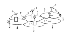
(移動通信システム)
図1は、本発明の第1の実施の形態に係る移動通信システムの構成を示す説明図である。図1に示すように、移動通信システムは、移動通信サービスを提供するサービスエリア全体をいくつかの無線ゾーンに分割したセル3を用いて、移動通信サービスを提供している。このような移動通信システムは、セル3をカバーし、セル3に存在する移動局2と通信を行う複数の基地局1と、これらの基地局1と通信を行う移動局2とから構成されている。基地局1は、CDMAにより、自局がカバーするセル3内に存在する移動局2と無線回線を設定して通信を行う。
【0033】
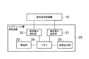
(トラフィック量測定装置)
次に、本実施形態に係るトラフィック量測定装置20について、詳細に説明する。図2は、本発明の第1の実施の形態に係るトラフィック量測定装置20の構成を示す機能ブロック図である。トラフィック量測定装置20は、基地局1に設けられ、基地局受信装置10と接続される。尚、トラフィック量測定装置20を用いて、トラフィック量についてシミュレーションを行う場合等は、トラフィック量測定装置20は、基地局1に設けられる必要はない。基地局受信装置10は、移動局2から送信される無線信号を受信する。トラフィック量測定装置20は、雑音電力設定部21と、雑音電力測定部22と、算出部23と、メモリ24と、結果出力部25とから構成される。
【0034】
雑音電力設定部21は、トラフィック量を測定する際の基準となる基地局1における基準雑音電力N1を設定する雑音電力設定手段である。雑音電力設定部21は、基準雑音電力N1として、基地局1におけるトラフィック量が0の場合の基地局1における雑音電力を設定することができる。即ち、雑音電力設定部21は、基準雑音電力N1として、基地局1が移動局2と全く無線回線を設定しておらず、基地局1がカバーするセル3内に移動局2が1つも存在しない状態で、移動局2間の干渉がない状態での基地局1における雑音電力とすることができる。これによれば、基準雑音電力N1を、基地局1毎に固有の決まった値とすることができる。
【0035】
又、雑音電力設定部21は、基準雑音電力N1として、予め設定された時間の基地局における雑音電力を設定することができる。時間は、一定の時刻を設定してもよく、一定の時間帯を設定してもよい。時間は、例えば毎朝6時といったような任意に選んだ時刻や、基地局1が空いている時刻や時間帯、基地局1が混雑する時刻や時間帯等を設定することができる。基地局1が空いているとは、基地局1に接続する移動局2の数が少ないことを意味し、基地局1が混雑するとは、基地局1に接続する移動局2の数が多いことを意味している。システム設計者は、予め基地局1に接続する移動局の数の時間経過に伴う変化を調べて、基地局1が混雑する時刻や空いている時間帯を把握し、時間を設定することができる。
【0036】
又、雑音電力設定部21は、基準雑音電力N1として、基地局1におけるトラフィック量が基地局1において許容される上限値の場合の基地局1における雑音電力を設定することができる。即ち、雑音電力設定部21は、基準雑音電力N1として、基地局1が許容できる上限値に相当する数の移動局2が、基地局1がカバーするセル3内に存在し、基地局1と無線回線を設定している状態での基地局1における雑音電力とすることができる。尚、上限値は、例えば、システム設計者等により設定されている。これによれば、基準雑音電力N1を基地局1毎に固有の決まった値とすることができる。
【0037】
又、雑音電力設定部21は、基地局受信装置10と接続して、トラフィック量が0の場合や、予め設定された時間、トラフィック量が上限値の場合における基地局受信装置10の雑音電力を測定し、その測定した雑音電力を基準雑音電力N1として設定することができる。又、雑音電力設定部21は、システム設計者等により与えられた雑音電力を、基準雑音電力として設定することもできる。更に、雑音電力設定部21は、トラフィック量が0の場合や、予め設定された時間、トラフィック量が上限値の場合における雑音電力がいくつになるかについてシミュレーションを行い、そのシミュレーション結果を基準雑音電力N1として設定することもできる。尚、図2において、雑音電力設定部21は、基地局受信装置10の雑音電力を測定する場合以外は、基地局受信装置10と接続する必要はない。
【0038】
又、雑音電力設定部21は、基準雑音電力N1を初期値として一度だけ設定してもよく、一定時間毎、毎日、毎週、毎月等、定期的に基準雑音電力N1を設定して変更してもよく、必要に応じて適宜、基準雑音電力N1を設定して変更してもよい。雑音電力設定部21は、メモリ24と接続しており、設定した基準雑音電力N1をメモリ24に記録する。
【0039】
雑音電力測定部22は、基地局1における雑音電力N2を測定する雑音電力測定手段である。上記したように、雑音電力は、基地局受信装置10自体が持っている熱雑音電力と、移動通信システムにおける全移動局2からの干渉雑音電力との総和をいい、いわゆる基地局1における干渉量をいう。雑音電力測定部22は、基地局受信装置10と接続して、基地局受信装置10の雑音電力N2を測定する。雑音電力測定部22は、基地局1におけるトラフィック量を求めたいある時点における雑音電力N2を測定する。よって、雑音電力測定部22は、定期的に、或いは、連続してトラフィック量を測定する場合には、それにあわせて雑音電力N2を定期的に測定したり連続して測定したりし、任意のタイミングでトラフィック量を測定する場合には、それにあわせて適宜、雑音電力N2を測定する。
【0040】
又、雑音電力測定部22は、トラフィック量のシミュレーションを行う場合には、基地局1におけるトラフィック量をシミュレーションしたいある時点における雑音電力N2を推定することにより、雑音電力N2を測定する。この場合には、雑音電力測定部22は、基地局受信装置10と接続する必要はない。雑音電力測定部22は、メモリ24と接続しており、測定した雑音電力N2をメモリ24に記録する。
【0041】
算出部23は、基準雑音電力N1及び雑音電力N2に基づいて、トラフィック量を算出する算出手段である。算出部23は、メモリ24と接続しており、メモリ24に保持された基準雑音電力N1、雑音電力N2を読み出す。算出部23は、読み出した基準雑音電力N1、雑音電力N2を以下に示す(1)式又は(1)'式に代入して、トラフィック量を算出する。
【0042】
【数9】
【0043】
算出部23は、トラフィック量をメモリ24に記録する。算出部23は、(1)式又は(1)'式により算出したトラフィック量をそのままメモリ24に記録してもよく、上記したように、%表示に換算したトラフィック量をメモリ24に記録してもよい。メモリ24は、基準雑音電力N1、雑音電力N2、トラフィック量を保持する。メモリ24は、雑音電力設定部21、雑音電力測定部22、算出部23、結果出力部25と接続している。
【0044】
結果出力部25は、トラフィック量を出力する出力手段である。結果出力部25は、メモリ24と接続しており、メモリ24に保持されたトラフィック量を読み出して出力する。結果出力部25は、メモリ24に保持されたトラフィック量をそのまま数値として出力してもよく、その数値を基にグラフを作成して、作成したグラフを出力してもよい。又、結果出力部25は、トラフィック量だけでなく、基準雑音電力N1、雑音電力N2も出力するようにしてもよい。
【0045】
このようなトラフィック量測定装置20は、例えば、コンピュータ30と測定装置40とにより構成し、コンピュータ30に、基地局1における基準雑音電力N1を設定するステップと、基地局1における雑音電力N2を取得するステップと、基準雑音電力N1及び雑音電力N2に基づいて、トラフィック量を算出するステップとを有する処理を実行させるトラフィック量測定プログラムを実行させることにより実現できる。
【0046】
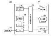
図3は、本発明の第1の実施の形態に係るトラフィック量測定装置20のハードウェア構成を示す図である。測定装置40は、基地局受信装置10と接続して、基地局受信装置10の雑音電力を測定する。又、測定装置40は、コンピュータ30と接続されている。コンピュータ30は、主制御部31と、記憶装置32と、入出力制御部33と、メモリ34と、入力装置35と、インタフェース(I/F)36と、表示装置37と、出力装置38とから構成される。各構成は、バス等で接続されている。
【0047】
記憶装置32には、上記したトラフィック量測定プログラムが記録されている。即ち、記憶装置32は、トラフィック量測定プログラムを記録した記録媒体である。尚、記録媒体は、記憶装置32に限定されず、CD−RやMO、フロッピーディスク等のリムーバブルメディアを用いることができる。CPU等の主制御部31は、記憶装置32からトラフィック量測定プログラムを読み出して実行することにより、主制御部31自身、入出力制御部33、入力装置35、インタフェース(I/F)36、表示装置37、出力装置38を、トラフィック量測定装置20の各手段として機能させる。尚、CPU等の主制御部31は、上記リムーバブルメディア等のコンピュータ30の外部から、トラフィック量測定プログラムを読み出して実行してもよい。
【0048】
入出力制御部33は、主制御部31や入力装置35、インタフェース36から入力されたデータを、メモリ34に記録する。又、入出力制御部33は、メモリ34に保持されたデータを取り出し、主制御部31や表示装置37、出力装置38に伝送する。メモリ34は、メモリ24と同様に、基準雑音電力N1、雑音電力N2、トラフィック量等のデータを保持する。入力装置35は、例えば、キーボード等であり、システム設計者等により入力されたデータを、入出力制御部33に伝送する。インタフェース36は、測定装置40や、外部のCD−RやMO、フロッピーディスク等のリムーバブルメディア等の外部装置からデータを取得し、入出力制御部33に伝送する。表示装置37は、例えば、ディスプレイやメータ等であり、入出力制御部33から伝送された数値やグラフを表示する。出力装置38は、例えば、プリンタ等であり、入出力制御部33から伝送された数値やグラフを紙等の媒体に出力する。
【0049】
測定装置40と、インタフェース36と、入出力制御部33は、測定した基地局受信装置10の雑音電力を基準雑音電力N1として設定する場合の雑音電力設定部21として機能する。又、入力装置35と入出力制御部33、又は、インタフェース36と入出力制御部33は、システム設計者等により与えられた雑音電力を基準雑音電力N1として設定する場合や、シミュレーション結果を基準雑音電力N1として設定する場合の雑音電力設定部21として機能する。この場合、システム設計者等により与えられた雑音電力やシミュレーションに用いる雑音電力は、定期的に、或いは、最初に予め初期値として、キーボード等の入力装置35から入力されたり、インタフェース36が外部のCD−RやMO、フロッピーディスク等のリムーバブルメディアから取得したりし、入出力制御部33によってメモリ34に記録される。
【0050】
測定装置40と、インタフェース36と、入出力制御部33は、雑音電力測定部22として機能する。又、トラフィック量のシミュレーションを行う場合には、入力装置35と入出力制御部33、又は、インタフェース36と入出力制御部33が、雑音電力測定部22として機能する。この場合、システム設計者等により与えられるシミュレーションに用いる雑音電力は、キーボード等の入力装置35から入力されたり、インタフェース36が、外部のCD−RやMO、フロッピーディスク等のリムーバブルメディアから取得したりし、入出力制御部33によってメモリ34に記録される。
【0051】
主制御部31と、入出力制御部33は、算出部23として機能する。表示装置37や出力装置38と、入出力制御部33は、結果出力部25として機能する。尚、メモリ24に保持されたトラフィック量を基にグラフを作成して、作成したグラフを出力する場合には、入出力制御部33は、メモリ34から読み出したトラフィック量を基にグラフを作成し、表示装置37や出力装置38に伝送する。
【0052】
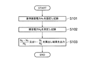
(トラフィック量測定方法)
次に、上記トラフィック量測定装置20を用いたトラフィック量測定方法について説明する。図4は、本発明の第1の実施の形態に係るトラフィック量測定方法の手順を示すフロー図である。まず、雑音電力設定部21が、基準雑音電力N1を設定し、メモリ24に記録する(S101)。次に、雑音電力測定部22が、雑音電力N2を測定し、メモリ24に記録する(S102)。最後に、算出部23が、メモリ24から基準雑音電力N1と、雑音電力N2を読み出して、(1)式又は(1)'式に代入して、トラフィック量を算出し、メモリ24に記録する。そして、結果出力部25が、メモリ24からトラフィック量を読み出して出力する(S103)。
【0053】
尚、ステップ(S101)と、ステップ(S102)は、順番を反対にし、先に、雑音電力測定部22が雑音電力N2を測定し、次に、雑音電力設定部21が基準雑音電力N1を設定するようにしてもよい。又、トラフィック量を連続して、又は、定期的に測定する場合には、ステップ(S101)〜ステップ(S103)を繰り返して、トラフィック量を測定する度に基準雑音電力N1を設定するようにしてもよく、初回だけステップ(S101)を行って、一度だけ基準雑音電力N1を設定し、次回からは、ステップ(S102)、(S103)だけを繰り返し、雑音電力N2だけを繰り返し測定して、トラフィック量を算出するようにしてもよい。
【0054】
(シミュレーション)
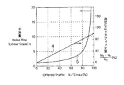
次に、上記トラフィック量測定装置20、トラフィック量測定方法を用いてトラフィック量の測定をシミュレーションした結果を示す。簡単のために、他の基地局1からの干渉(他セル干渉)がない場合についてシミュレーションした。又、比較のために、従来、トラフィック負荷を知るために用いていた干渉量についてもシミュレーションを行った。図5は、トラフィック量の測定のシミュレーション結果を示すグラフ図である。図5の横軸は、N/Cmax(%)である。Nは、基地局1に接続している実際のユーザ数であり、Cmaxは、基地局1の限界容量である。よって、横軸であるN/Cmaxは、ユーザ数Nの限界容量Cmaxに対する割合を示している。又、図5の左側の縦軸は、干渉量ηであり、図5の右側の縦軸は、トラフィック量測定装置20が測定したトラフィック量(%)である。
【0055】
直線4は、トラフィック量測定装置20が、基準雑音電力N1を、基地局1におけるトラフィック量が0の場合の雑音電力に設定し、(1)式又は(1)'式により算出した値に100を乗じて、%表示に換算することにより測定したトラフィック量(%)を示し、右側の縦軸に従ってプロットしたものである。曲線5は、以下に示す(5)式により求めた干渉量ηを示し、左側の縦軸に従ってプロットしたものである。
【0056】
【数11】
【0057】
図5から明らかなように、トラフィック量測定装置20が測定したトラフィック量を示す直線4は、N/Cmaxに正比例しており、トラフィック量測定装置20によれば、基地局1における実際のユーザ数Nに正比例した正確なトラフィック量を求められることが分かった。よって、トラフィック量測定装置20によれば、基地局1における実際のトラフィック負荷の状況を適切に反映したトラフィック量を求められることが分かった。一方、干渉量ηを示す曲線5は、N/Cmaxに正比例しておらず、干渉量ηは、基地局1における実際のユーザ数Nに正比例していない。特に、干渉量ηは、N/Cmaxの値が小さい時、即ち、基地局1における実際のユーザ数Nが少なく、トラフィック負荷が小さい低負荷時には、実際のトラフィック量を示す直線4よりも過小評価となっており、実際のトラフィック負荷の状況を適切に反映することができていなかった。
【0058】
ここで、図5の横軸であるN/Cmaxは、以下の(6)式により計算することができる。
【0059】
【数12】
【0060】
【数13】
【0061】
(作用効果)
このような第1の実施の形態に係るトラフィック量測定装置20、トラフィック量測定方法、トラフィック量測定プログラム及びトラフィック量測定プログラムを記録した記録媒体によれば、雑音電力設定部21がトラフィック量を測定する際の基準となる基準雑音電力N1を設定し、雑音電力測定部22が、基地局1における実際の雑音電力N2を測定する。そして、算出部23が、実際に測定した雑音電力N2だけでなく、基準となる基準雑音電力N1に基づいて、トラフィック量を算出する。そのため、トラフィック量測定装置20は、基準雑音電力N1に対して、実際の雑音電力N2がどの程度であるかを求めることができ、基地局におけるトラフィック量を正確に求めることができる。
【0062】
よって、トラフィック量測定装置20は、図5からも明らかなように、CDMAを用いて通信を行う基地局1の上り回線におけるトラフィック負荷の状況を適切に反映したトラフィック量を求めることができ、基地局1の上り回線におけるトラフィック負荷の状況を適切に把握することができる。その結果、求めたトラフィック量を用いて、基地局1の設備設計を正確に行うことができる。
【0063】
更に、トラフィック量測定装置20は、基準雑音電力N1を設定し、実際の雑音電力N2を測定するだけで、簡単にトラフィック量を求めることができる。加えて、雑音電力N2は、既存の基地局1において通常、測定されている値である。よって、既存の基地局1は、雑音電力N2を測定する機能を備えていることが多い。よって、トラフィック量測定装置20は、既存の基地局1にある現在利用されている機能を使用し、新たな機能を設けることなく測定可能な雑音電力N2を用いることにより、簡単にトラフィック量を求めることができる。
【0064】
以上説明したように、トラフィック量測定装置20は、基地局1の設備設計を行う上で非常に重要な上り回線のトラフィック量の需要や実際のトラフィック量を、簡単に、かつ、精度よく把握することができる。
【0065】
又、算出部23が、(1)式又は(1)'式により、トラフィック量を算出するため、図5からも明らかなように、基地局1における実際のユーザ数に正比例した正確なトラフィック量を求めることができる。よって、トラフィック量測定装置20は、(1)式又は(1)'式のような簡単な式を用いた計算を行うことにより、基地局1の上り回線におけるトラフィック負荷の状況を適切に反映したトラフィック量を求めることができる。
【0066】
[第2の実施の形態]
以下、図面を参照して、本発明の第2の実施の形態について説明する。本実施形態では、基地局1に設けられるトラフィック量測定装置220が異なる以外は、第1の実施の形態と同様である。
【0067】
(トラフィック量測定装置)
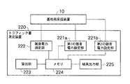
図6は、本発明の第2の実施の形態に係るトラフィック量測定装置220の構成を示す機能ブロック図である。トラフィック量測定装置220は、基地局1に設けられ、基地局受信装置10と接続される。トラフィック量測定装置220は、第1の雑音電力設定部221aと、第2の雑音電力設定部221bと、雑音電力測定部222と、算出部223と、メモリ224と、結果出力部225とから構成される。
【0068】
第1の雑音電力設定部221aと、第2の雑音電力設定部221bは、トラフィック量を測定する際の基準となる基地局1における基準雑音電力を、複数設定する雑音電力設定手段を構成する。本実施形態では、基準雑音電力を2つ設定し、一方を基準雑音電力N1、他方を基準雑音電力N3とする。第1の雑音電力設定部221aが、基準雑音電力N1を設定し、第2の雑音電力設定部221bが、基準雑音電力N3を設定する。基準雑音電力N1と基準雑音電力N3は、異なる値であればよい。
【0069】
よって、第1の雑音電力設定部221a、第2の雑音電力設定部221bは、第1の実施の形態の雑音電力設定部21と同様の基地局1におけるトラフィック量が0の場合の基地局1における雑音電力、予め設定された時間の基地局における雑音電力、基地局1におけるトラフィック量が基地局1において許容される上限値の場合の基地局1における雑音電力等の中から、互いに異なる雑音電力を、基準雑音電力N1、基準雑音電力N3として、設定することができる。
【0070】
但し、基準雑音電力N3は、基準雑音電力N1よりも大きい方が好ましい。そのため、第1の雑音電力設定部221aは、基準雑音電力N1として、基地局1におけるトラフィック量が0の場合の基地局1における雑音電力や、予め設定された基地局1が空いている時刻や時間帯における雑音電力を設定することが好ましい。一方、第2の雑音電力設定部221bは、基準雑音電力N3として、基地局1におけるトラフィック量が基地局1において許容される上限値の場合の基地局1における雑音電力や、予め設定された基地局1が混雑する時刻や時間帯における雑音電力を設定することが好ましい。
【0071】
又、第1の雑音電力設定部221a、第2の雑音電力設定部221bは、第1の実施の形態と同様に、基地局受信装置10と接続して、基地局受信装置10の雑音電力を測定し、その測定した雑音電力を基準雑音電力N1や基準雑音電力N3として設定してもよく、システム設計者等により与えられた雑音電力を、基準雑音電力N1や基準雑音電力N3として設定してもよく、シミュレーションを行い、そのシミュレーション結果を基準雑音電力N1や基準雑音電力N3として設定してもよい。尚、図6において、第1の雑音電力設定部221a、第2の雑音電力設定部221bは、基地局受信装置10の雑音電力を測定する場合以外は、基地局受信装置10と接続する必要はない。
【0072】
又、第1の雑音電力設定部221a、第2の雑音電力設定部221bは、基準雑音電力N1、基準雑音電力N3を初期値として一度だけ設定してもよく、定期的に設定して変更してもよく、必要に応じて適宜設定して変更してもよい。第1の雑音電力設定部221a、第2の雑音電力設定部221bは、メモリ224と接続しており、設定した基準雑音電力N1、基準雑音電力N3を、それぞれメモリ224に記録する。雑音電力測定部222は、第1の実施の形態に係る雑音電力測定部22と実質的に同様である。
【0073】
算出部223は、基準雑音電力N1、基準雑音電力N3及び雑音電力N2に基づいて、トラフィック量を算出する算出手段である。算出部223は、メモリ224と接続しており、メモリ224に保持された基準雑音電力N1、基準雑音電力N3、雑音電力N2を読み出す。算出部223は、読み出した基準雑音電力N1、基準雑音電力N3、雑音電力N2を以下に示す(2)式又は(2)'式に代入して、トラフィック量を算出する。
【0074】
【数14】
【0075】
これによれば、基地局1における上り回線のトラフィック負荷がどの程度であるかを、%表示で表されたトラフィック量から知ることができる。具体的には、基地局1における上り回線のトラフィック負荷が、基準雑音電力N1、基準雑音電力N3によって定まる値に対して、どの程度であるかを知ることができる。よって、基準雑音電力N1は、トラフィック量が0の場合の雑音電力に設定することが好ましい。
【0076】
算出部223は、トラフィック量をメモリ224に記録する。算出部223は、(2)式又は(2)'式により算出したトラフィック量をそのままメモリ224に記録してもよく、上記したように、%表示に換算したトラフィック量をメモリ224に記録してもよい。メモリ224は、基準雑音電力N1、基準雑音電力N3、雑音電力N2、トラフィック量を保持する。メモリ224は、第1の雑音電力設定部221a、第2の雑音電力設定部221b、雑音電力測定部222、算出部223、結果出力部225と接続している。結果出力部225は、第1の実施の形態に係る結果出力部25と、実質的に同様である。
【0077】
このようなトラフィック量測定装置220も、第1の実施の形態と同様に、例えば、図3に示すようなコンピュータ30と測定装置40とにより構成し、コンピュータ30に、基地局1における複数の基準雑音電力N1、基準雑音電力N3を設定するステップと、基地局1における雑音電力N2を取得するステップと、基準雑音電力N1、基準雑音電力N3及び雑音電力N2に基づいて、トラフィック量を算出するステップとを有する処理を実行させるトラフィック量測定プログラムを、実行させることにより実現できる。
【0078】
本実施形態では、測定装置40と、インタフェース36と、入出力制御部33は、測定した基地局受信装置10の雑音電力を基準雑音電力N1、基準雑音電力N3として設定する場合の第1の雑音電力設定部221aや第2の雑音電力設定部221bとして機能する。又、入力装置35と入出力制御部33、又は、インタフェース36と入出力制御部33は、システム設計者等により与えられた雑音電力を基準雑音電力N1、基準雑音電力N3として設定する場合や、シミュレーション結果を基準雑音電力N1、基準雑音電力N3として設定する場合の第1の雑音電力設定部221aや第2の雑音電力設定部221bとして機能する。
【0079】
この場合、システム設計者等により与えられた雑音電力やシミュレーションに用いる雑音電力は、定期的に、或いは、最初に予め初期値として、キーボード等の入力装置35から入力されたり、インタフェース36が外部のCD−RやMO、フロッピーディスク等のリムーバブルメディアから取得したりし、入出力制御部33によってメモリ34に記録される。又、主制御部31と、入出力制御部33は、算出部223として機能する。これらの点以外は、コンピュータ30と測定装置40は、第1の実施の形態と実質的に同様に機能して、トラフィック量測定装置220の各手段を実現する。
【0080】
(トラフィック量測定方法)
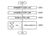
次に、上記トラフィック量測定装置220を用いたトラフィック量測定方法について説明する。図7は、本発明の第2の実施の形態に係るトラフィック量測定方法の手順を示すフロー図である。まず、第1の雑音電力設定部221aが、基準雑音電力N1を設定し、メモリ224に記録する(S201)。次に、第2の雑音電力設定部221bが、基準雑音電力N3を設定し、メモリ224に記録する(S202)。次に、雑音電力測定部222が、雑音電力N2を測定し、メモリ224に記録する(S203)。最後に、算出部223が、メモリ224から基準雑音電力N1、基準雑音電力N3、雑音電力N2を読み出して、(2)式又は(2)'式に代入して、トラフィック量を算出し、メモリ224に記録する。そして、結果出力部225が、メモリ224からトラフィック量を読み出して出力する(S204)。
【0081】
尚、ステップ(S201)〜(S203)は、必ずしもこの順番で行う必要はなく、ステップ(S203)、(S202)、(S201)の順番で行ったり、ステップ(S201)〜(S203)のうち、2つの順番を入れ替えて行ったりしてもよい。又、トラフィック量を連続して、又は、定期的に測定する場合には、ステップ(S201)〜(S203)を繰り返して、トラフィック量を測定する度に基準雑音電力N1、基準雑音電力N3を設定するようにしてもよく、初回だけステップ(S201)、(S202)を行って、一度だけ基準雑音電力N1、基準雑音電力N3を設定し、次回からは、ステップ(S203)、(S204)だけを繰り返し、雑音電力N2だけを繰り返し測定するようにして、トラフィック量を算出するようにしてもよい。
【0082】
(シミュレーション)
次に、第1の実施の形態と同様にして、上記トラフィック量測定装置220、トラフィック量測定方法を用いてトラフィック量の測定をシミュレーションしたところ、トラフィック量測定装置220が測定したトラフィック量も、図5に示す直線4のように、N/Cmaxに正比例した値となり、トラフィック量測定装置220によれば、基地局1における実際のユーザ数Nに正比例した正確なトラフィック量を求められることが分かった。又、(6)式を、他の基地局1からの干渉(他セル干渉)がないとし、若干の数学的操作を行いながら展開していくことにより、(2)式、(2)'式を得ることができた。よって、(2)式、(2)'式は、実際のユーザ数Nに正比例した正確なトラフィック量を示していることが分かった。
【0083】
(作用効果)
このような第2の実施の形態に係るトラフィック量測定装置220、トラフィック量測定方法、トラフィック量測定プログラム及びトラフィック量測定プログラムを記録した記録媒体によれば、第1の雑音電力設定部221a、第2の雑音電力設定部221bが、複数の基準雑音電力N1、基準雑音電力N3を設定し、算出部223が、複数の基準雑音電力N1、基準雑音電力N3及び雑音電力N2に基づいて、トラフィック量を算出する。そのため、算出部223は、基準となる複数の基準雑音電力N1、基準雑音電力N3を用いてトラフィック量を算出することができる。よって、トラフィック量測定装置220は、複数の基準雑音電力N1、基準雑音電力N3に対して、実際の雑音電力N2がどの程度であるかを求めることができ、基地局1におけるトラフィック量をより正確に求めることができる。従って、CDMAを用いて通信を行う基地局1の上り回線におけるトラフィック負荷の状況をより適切に反映したトラフィック量を求めることができる。
【0084】
又、算出部223が、(2)式又は(2)'式により、トラフィック量を算出するため、基地局1における実際のユーザ数に正比例した正確なトラフィック量を求めることができる。よって、トラフィック量測定装置220は、(2)式又は(2)'式のような簡単な式を用いた計算を行うことにより、基地局1の上り回線におけるトラフィック負荷の状況を適切に反映したトラフィック量を求めることができる。
【0085】
[第3の実施の形態]
以下、図面を参照して、本発明の第3の実施の形態について説明する。本実施形態では、基地局1に設けられるトラフィック量測定装置320、基地局送信装置50が異なる以外は、第1の実施の形態と同様である。
【0086】
(トラフィック量測定装置)
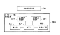
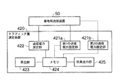
図8は、本発明の第3の実施の形態に係るトラフィック量測定装置320の構成を示す機能ブロック図である。トラフィック量測定装置320は、基地局1に設けられ、基地局送信装置50と接続される。基地局受信装置50は、基地局1から移動局2に対する無線信号を送信する。トラフィック量測定装置320は、送信電力設定部321と、送信電力測定部322と、算出部323と、メモリ324と、結果出力部325とから構成される。
【0087】
送信電力設定部321は、トラフィック量を測定する際の基準となる基地局1における基準送信電力P1を設定する送信電力設定手段である。送信電力設定部321は、基準送信電力P1として、基地局1におけるトラフィック量が0の場合の基地局1における送信電力を設定することができる。即ち、送信電力設定部321は、基準送信電力P1として、基地局1が移動局2と全く無線回線を設定しておらず、基地局1がカバーするセル3内に移動局2が1つも存在しない状態で、移動局2間の干渉がない状態での基地局1における総送信電力とすることができる。
【0088】
基地局送信装置50は、下り回線において、CPICH等の共通パイロット信号を送信する共通パイロットチャネルや、PCCPCH等の報知情報を送信する報知情報チャネルを、常時送信している。よって、基地局1におけるトラフィック量が0の場合であっても、基地局1には、共通パイロットチャネルや報知情報チャネルを送信するための一定の送信電力が常に存在している。よって、送信電力設定部221aは、この一定の送信電力を、基準送信電力P1として設定することができる。これによれば、基準雑音電力P1を、基地局1毎に固有の決まった値とすることができる。
【0089】
又、送信電力設定部321は、基準送信電力P1として、予め設定された時間の基地局における送信電力を設定することができる。時間は、一定の時刻を設定してもよく、一定の時間帯を設定してもよい。時間は、例えば毎朝6時といったような任意に選んだ時刻や、基地局1が空いている時刻や時間帯、基地局1が混雑する時刻や時間帯等を設定することができる。
【0090】
又、送信電力設定部321は、基準送信電力P1として、基地局1における最大送信電力を設定することができる。基地局1における最大送信電力は、基地局送信装置50の最大能力の送信電力である。これによれば、基準送信電力P1を基地局1毎に固有の決まった値とすることができる。
【0091】
又、送信電力設定部321は、基地局送信装置50と接続して、トラフィック量が0の場合や、予め設定された時間における基地局送信装置50の送信電力を測定し、その測定した送信電力を基準送信電力P1として設定することができる。又、送信電力設定部321は、システム設計者等により与えられた送信電力を、基準送信電力として設定してもよい。更に、送信電力設定部321は、トラフィック量が0の場合や、予め設定された時間における送信電力がいくつになるかについてシミュレーションを行い、そのシミュレーション結果を基準送信電力P1として設定することもできる。尚、図8において、送信電力設定部321は、基地局送信装置50の送信電力を測定する場合以外は、基地局送信装置50と接続する必要はない。
【0092】
又、送信電力設定部321は、基準送信電力P1を初期値として一度だけ設定してもよく、定期的に基準送信電力P1を設定して変更してもよく、必要に応じて適宜、基準送信電力P1を設定して変更してもよい。送信電力設定部321は、メモリ324と接続しており、設定した基準送信電力N1をメモリ324に記録する。
【0093】
送信電力測定部322は、基地局1における送信電力P2を測定する送信電力測定手段である。送信電力測定部322は、基地局送信装置50と接続して、基地局送信装置50の送信電力P2を測定する。送信電力測定部322は、基地局1におけるトラフィック量を求めたいある時点における総送信電力P2を測定する。よって、送信電力測定部322は、定期的に、或いは、連続してトラフィック量を測定する場合には、それにあわせて送信電力P2を定期的に測定したり連続して測定したりし、任意のタイミングでトラフィック量を測定する場合には、それにあわせて適宜、送信電力P2を測定する。
【0094】
又、送信電力測定部322は、トラフィック量のシミュレーションを行う場合には、基地局1におけるトラフィック量をシミュレーションしたいある時点における送信電力P2を推定することにより、送信電力P2を測定する。この場合には、送信電力測定部322は、基地局送信装置50と接続する必要はない。送信電力測定部322は、メモリ324と接続しており、測定した送信電力P2をメモリ324に記録する。
【0095】
算出部323は、基準送信電力P1及び送信電力P2に基づいて、トラフィック量を算出する算出手段である。算出部323は、メモリ324と接続しており、メモリ324に保持された基準送信電力P1、送信電力P2を読み出す。算出部323は、読み出した基準送信電力P1、送信電力P2を以下に示す(3)式又は(3)'式に代入して、トラフィック量を算出する。
【0096】
【数16】
【0097】
算出部323は、トラフィック量をメモリ324に記録する。算出部323は、(3)式又は(3)'式により算出したトラフィック量をそのままメモリ324に記録してもよく、上記したように、%表示に換算したトラフィック量をメモリ324に記録してもよい。
【0098】
メモリ324は、基準送信電力P1、送信電力P2、トラフィック量を保持する。メモリ324は、送信電力設定部321、送信電力測定部322、算出部323、結果出力部325と接続している。結果出力部325は、第1の実施の形態に係る結果出力部25と実質的に同様である。
【0099】
このようなトラフィック量測定装置320も、第1の実施の形態と同様に、例えば、図3に示すようなコンピュータ30と測定装置40とにより構成し、コンピュータ30に、基地局1における基準送信電力P1を設定するステップと、基地局1における送信電力P2を取得するステップと、基準送信電力P1及び送信電力P2に基づいて、トラフィック量を算出するステップとを有する処理を実行させるトラフィック量測定プログラムを、実行させることにより実現できる。尚、本実施形態では、測定装置40は、基地局送信装置50と接続して、基地局送信装置50の送信電力を測定する。
【0100】
本実施形態では、測定装置40と、インタフェース36と、入出力制御部33は、測定した基地局送信装置50の送信電力を基準送信電力P1として設定する場合の送信電力設定部321として機能する。又、入力装置35と入出力制御部33、又は、インタフェース36と入出力制御部33は、システム設計者等により与えられた送信電力を基準送信電力P1として設定する場合や、シミュレーション結果を基準送信電力P1として設定する場合の送信電力設定部321として機能する。この場合、システム設計者等により与えられた送信電力やシミュレーションに用いる送信電力は、定期的に、或いは、最初に予め初期値として、キーボード等の入力装置35から入力されたり、インタフェース36が外部のCD−RやMO、フロッピーディスク等のリムーバブルメディアから取得したりし、入出力制御部33によってメモリ34に記録される。
【0101】
測定装置40と、インタフェース36と、入出力制御部33は、送信電力測定部322として機能する。又、トラフィック量のシミュレーションを行う場合には、入力装置35と入出力制御部33、又は、インタフェース36と入出力制御部33が、送信電力測定部322として機能する。この場合、システム設計者等により与えられるシミュレーションに用いる送信電力は、キーボード等の入力装置35から入力されたり、インタフェース36が、外部のCD−Rや、MO、フロッピーディスク等のリムーバブルメディアから取得したりし、入出力制御部33によってメモリ34に記録される。主制御部31と、入出力制御部33は、算出部323として機能する。表示装置37や出力装置38と、入出力制御部33は、結果出力部325として機能する。
【0102】
(トラフィック量測定方法)
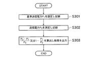
次に、上記トラフィック量測定装置320を用いたトラフィック量測定方法について説明する。図9は、本発明の第3の実施の形態に係るトラフィック量測定方法の手順を示すフロー図である。まず、送信電力設定部321が、基準送信電力P1を設定し、メモリ324に記録する(S301)。次に、送信電力測定部322が、送信電力P2を測定し、メモリ324に記録する(S302)。最後に、算出部323が、メモリ324から基準送信電力P1と、送信電力P2を読み出して、(3)式又は(3)'式に代入して、トラフィック量を算出し、メモリ324に記録する。そして、結果出力部325が、メモリ324からトラフィック量を読み出して出力する(S303)。
【0103】
尚、ステップ(S301)と、ステップ(S302)は、順番を反対にし、先に、送信電力測定部322が送信電力P2を測定し、次に、送信電力設定部321が基準送信電力P1を設定するようにしてもよい。又、トラフィック量を連続して、又は、定期的に測定する場合には、ステップ(S301)〜ステップ(S303)を繰り返して、トラフィック量を測定する度に基準送信電力P1を設定するようにしてもよく、初回だけステップ(S301)を行って、一度だけ基準送信電力P1を設定し、次回からは、ステップ(S302)、(S303)だけを繰り返し、送信電力P2だけを繰り返し測定して、トラフィック量を算出するようにしてもよい。
【0104】
(シミュレーション)
次に、第1の実施の形態と同様にして、上記トラフィック量測定装置320、トラフィック量測定方法を用いてトラフィック量の測定をシミュレーションしたところ、トラフィック量測定装置320が測定したトラフィック量も、図5に示す直線4のように、N/Cmaxに正比例した値となり、トラフィック量測定装置320によれば、基地局1における実際のユーザ数Nに正比例した正確なトラフィック量を求められることが分かった。
【0105】
ここで、図5の横軸であるN/Cmaxは、以下の(8)式により計算することができる。
【0106】
【数18】
【0107】
(8)式の分母は、基準送信電力P1、基準送信電力P3として設定される値であるため、(8)式からも、(8)式の分子に相当する(3)式、(3)'式は、実際のユーザ数Nに正比例した正確なトラフィック量を示していることが分かった。
【0108】
(作用効果)
このような第3の実施の形態に係るトラフィック量測定装置320、トラフィック量測定方法、トラフィック量測定プログラム及びトラフィック量測定プログラムを記録した記録媒体によれば、送信電力設定部321がトラフィック量を測定する際の基準となる基準送信電力P1を設定し、送信電力測定部322が、基地局1における実際の送信電力P2を測定する。そして、算出部323が、実際に測定した送信電力P2だけでなく、基準となる基準送信電力P1に基づいて、トラフィック量を算出する。そのため、トラフィック量測定装置320は、基準送信電力P1に対して、実際の送信電力P2がどの程度であるかを求めることができ、基地局におけるトラフィック量を正確に求めることができる。
【0109】
よって、トラフィック量測定装置320は、CDMAを用いて通信を行う基地局1の下り回線におけるトラフィック負荷の状況を適切に反映したトラフィック量を求めることができ、基地局1の下り回線におけるトラフィック負荷の状況を適切に把握することができる。その結果、求めたトラフィック量を用いて、基地局1の設備設計を正確に行うことができる。
【0110】
更に、トラフィック量測定装置320は、基準送信電力P1を設定し、実際の送信電力P2を測定するだけで、簡単にトラフィック量を求めることができる。加えて、送信電力P2は、既存の基地局1において通常、測定されている値である。よって、既存の基地局1は、送信電力P2を測定する機能を備えていることが多い。よって、トラフィック量測定装置320は、既存の基地局1にある現在利用されている機能を使用し、新たな機能を設けることなく測定可能な雑音電力P2を用いることにより、簡単にトラフィック量を求めることができる。
【0111】
以上説明したように、トラフィック量測定装置320は、基地局1の設備設計を行う上で非常に重要な下り回線のトラフィック量の需要や実際のトラフィック量を、簡単に、かつ、精度よく把握することができる。
【0112】
又、算出部323が、(3)式又は(3)'式により、トラフィック量を算出するため、基地局1における実際のユーザ数に正比例した正確なトラフィック量を求めることができる。よって、トラフィック量測定装置320は、(3)式又は(3)'式のような簡単な式を用いた計算を行うことにより、基地局1の下り回線におけるトラフィック負荷の状況を適切に反映したトラフィック量を求めることができる。
【0113】
[第4の実施の形態]
以下、図面を参照して、本発明の第4の実施の形態について説明する。本実施形態では、基地局1に設けられるトラフィック量測定装置420が異なる以外は、第3の実施の形態と同様である。
【0114】
(トラフィック量測定装置)
図10は、本発明の第4の実施の形態に係るトラフィック量測定装置420の構成を示す機能ブロック図である。トラフィック量測定装置420は、基地局1に設けられ、基地局送信装置50と接続される。トラフィック量測定装置420は、第1の送信電力設定部421aと、第2の送信電力設定部421bと、送信電力測定部422と、算出部423と、メモリ424と、結果出力部425とから構成される。
【0115】
第1の送信電力設定部421aと、第2の送信電力設定部421bは、トラフィック量を測定する際の基準となる基地局1における基準送信電力を、複数設定する送信電力設定手段を構成する。本実施形態では、基準送信電力を2つ設定し、一方を基準送信電力P1、他方を基準送信電力P3とする。第1の送信電力設定部421aが、基準送信電力P1を設定し、第2の送信電力設定部421bが、基準送信電力P3を設定する。基準送信電力P1と基準P電力N3は、異なる値であればよい。
【0116】
よって、第1の送信電力設定部421a、第2の送信電力設定部421bは、第3の実施の形態の送信電力設定部321と同様の基地局1におけるトラフィック量が0の場合の基地局1における送信電力、予め設定された時間の基地局における送信電力、基地局1における最大送信電力等の中から、互いに異なる送信電力を、基準送信電力P1、基準送信電力P3として、設定することができる。
【0117】
但し、基準送信電力P3は、基準送信電力P1よりも大きい方が好ましい。そのため、第1の送信電力設定部421aは、基準送信電力P1として、基地局1におけるトラフィック量が0の場合の基地局1における送信電力や、予め設定された基地局1が空いている時刻や時間帯における送信電力を設定することが好ましい。一方、第2の送信電力設定部421bは、基準送信電力P3として、基地局1における最大送信電力や、予め設定された基地局1が混雑する時刻や時間帯における送信電力を設定することが好ましい。
【0118】
又、第1の送信電力設定部421a、第2の送信電力設定部421bは、第1の実施の形態と同様に、基地局送信装置50と接続して、基地局送信装置50の送信電力を測定し、その測定した送信電力を基準送信電力P1や基準送信電力P3として設定してもよく、システム設計者等により与えられた送信電力を、基準送信電力P1や基準送信電力P3として設定してもよく、シミュレーションを行い、そのシミュレーション結果を基準送信電力P1や基準送信電力P3として設定してもよい。尚、図10において、第1の送信電力設定部421a、第2の送信電力設定部421bは、基地局送信装置50の送信電力を測定する場合以外は、基地局送信装置50と接続する必要はない。
【0119】
又、第1の送信電力設定部421a、第2の送信電力設定部421bは、基準送信電力P1、基準送信電力P3を初期値として一度だけ設定してもよく、定期的に設定して変更してもよく、必要に応じて適宜設定して変更してもよい。第1の送信電力設定部421a、第2の送信電力設定部421bは、メモリ424と接続しており、設定した基準送信電力P1、基準送信電力P3を、それぞれメモリ424に記録する。送信電力測定部422は、第3の実施の形態に係る送信電力測定部322と実質的に同様である。
【0120】
算出部423は、基準送信電力P1、基準送信電力P3及び送信電力P2に基づいて、トラフィック量を算出する算出手段である。算出部423は、メモリ424と接続しており、メモリ424に保持された基準送信電力P1、基準送信電力P3、送信電力P2を読み出す。算出部423は、読み出した基準送信電力P1、基準送信電力P3、送信電力P2を以下に示す(4)式又は(4)'式に代入して、トラフィック量を算出する。
【0121】
【数19】
【0122】
これによれば、基地局1における下り回線のトラフィック負荷がどの程度であるかを、%表示で表されたトラフィック量から知ることができる。具体的には、基地局1における下り回線のトラフィック負荷が、基準送信電力P1、基準送信電力P3によって定まる値に対して、どの程度であるかを知ることができる。よって、基準送信電力P1は、トラフィック量が0の場合の送信電力に設定することが好ましい。
【0123】
算出部423は、トラフィック量をメモリ424に記録する。算出部423は、(4)式又は(4)'式により算出したトラフィック量をそのままメモリ424に記録してもよく、上記したように、%表示に換算したトラフィック量をメモリ424に記録してもよい。メモリ424は、基準送信電力P1、基準送信電力P3、送信電力P2、トラフィック量を保持する。メモリ424は、第1の送信電力設定部421a、第2の送信電力設定部421b、送信電力測定部422、算出部423、結果出力部425と接続している。結果出力部425は、第1の実施の形態に係る結果出力部25と、実質的に同様である。
【0124】
このようなトラフィック量測定装置420も、第1の実施の形態と同様に、例えば、図3に示すようなコンピュータ30と測定装置40とにより構成し、コンピュータ30に、基地局1における複数の基準送信電力P1、基準送信電力P3を設定するステップと、基地局1における送信電力P2を取得するステップと、基準送信電力P1、基準送信電力P3及び送信電力P2に基づいて、トラフィック量を算出するステップとを有する処理を実行させるトラフィック量測定プログラムを、実行させることにより実現できる。尚、本実施形態では、測定装置40は、基地局送信装置50と接続して、基地局送信装置50の送信電力を測定する。
【0125】
本実施形態では、測定装置40と、インタフェース36と、入出力制御部33は、測定した基地局受信装置50の送信電力を基準送信電力P1、基準送信電力P3として設定する場合の第1の送信電力設定部421aや第2の送信電力設定部421bとして機能する。又、入力装置35と入出力制御部33、又は、インタフェース36と入出力制御部33は、システム設計者等により与えられた送信電力を基準送信電力P1、基準送信電力P3として設定する場合や、シミュレーション結果を基準送信電力P1、基準送信電力P3として設定する場合の第1の送信電力設定部421aや第2の送信電力設定部421bとして機能する。
【0126】
この場合、システム設計者等により与えられた送信電力やシミュレーションに用いる送信電力は、定期的に、或いは、最初に予め初期値として、キーボード等の入力装置35から入力されたり、インタフェース36が外部のCD−RやMO、フロッピーディスク等のリムーバブルメディアから取得したりし、入出力制御部33によってメモリ34に記録される。又、主制御部31と、入出力制御部33は、算出部423として機能する。これらの点以外は、コンピュータ30と測定装置40は、第3の実施の形態と実質的に同様に機能して、トラフィック量測定装置420の各手段を実現する。
【0127】
(トラフィック量測定方法)
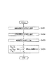
次に、上記トラフィック量測定装置420を用いたトラフィック量測定方法について説明する。図11は、本発明の第4の実施の形態に係るトラフィック量測定方法の手順を示すフロー図である。まず、第1の送信電力設定部421aが、基準送信電力P1を設定し、メモリ424に記録する(S401)。次に、第2の送信電力設定部421bが、基準送信電力P3を設定し、メモリ424に記録する(S402)。次に、送信電力測定部422が、送信電力P2を測定し、メモリ424に記録する(S403)。最後に、算出部423が、メモリ424から基準送信電力P1、基準送信電力P3、送信電力P2を読み出して、(4)式又は(4)'式に代入して、トラフィック量を算出し、メモリ424に記録する。そして、結果出力部425が、メモリ424からトラフィック量を読み出して出力する(S404)。
【0128】
尚、ステップ(S401)〜(S403)は、必ずしもこの順番で行う必要はなく、ステップ(S403)、(S402)、(S401)の順番で行ったり、ステップ(S401)〜(S403)のうち、2つの順番を入れ替えて行ったりしてもよい。又、トラフィック量を連続して、又は、定期的に測定する場合には、ステップ(S401)〜(S403)を繰り返して、トラフィック量を測定する度に基準送信電力P1、基準送信電力P3を設定するようにしてもよく、初回だけステップ(S401)、(S402)を行って、一度だけ基準送信電力P1、基準送信電力P3を設定し、次回からは、ステップ(S403)、(S404)だけを繰り返し、送信電力P2だけを繰り返し測定するようにして、トラフィック量を算出するようにしてもよい。
【0129】
(シミュレーション)
次に、第1の実施の形態と同様にして、上記トラフィック量測定装置420、トラフィック量測定方法を用いてトラフィック量の測定をシミュレーションしたところ、トラフィック量測定装置420が測定したトラフィック量も、図5に示す直線4のように、N/Cmaxに正比例した値となり、トラフィック量測定装置420によれば、基地局1における実際のユーザ数Nに正比例した正確なトラフィック量を求められることが分かった。又、上記した(8)式からも、(4)式、(4)'式が、実際のユーザ数Nに正比例した正確なトラフィック量を示していることが分かった。
【0130】
(作用効果)
このような第4の実施の形態に係るトラフィック量測定装置420、トラフィック量測定方法、トラフィック量測定プログラム及びトラフィック量測定プログラムを記録した記録媒体によれば、第1の送信電力設定部421a、第2の送信電力設定部421bが、複数の基準送信電力P1、基準送信電力P3を設定し、算出部423が、複数の基準送信電力P1、基準送信電力P3及び送信電力P2に基づいて、トラフィック量を算出する。そのため、算出部423は、基準となる複数の基準雑音電力P1、基準雑音電力P3を用いてトラフィック量を算出することができる。よって、トラフィック量測定装置420は、複数の基準送信電力P1、基準送信電力P3に対して、実際の送信電力P2がどの程度であるかを求めることができ、基地局1におけるトラフィック量をより正確に求めることができる。従って、CDMAを用いて通信を行う基地局1の下り回線におけるトラフィック負荷の状況をより適切に反映したトラフィック量を求めることができる。
【0131】
又、算出部423が、(4)式又は(4)'式により、トラフィック量を算出するため、基地局1における実際のユーザ数に正比例した正確なトラフィック量を求めることができる。よって、トラフィック量測定装置420は、(4)式又は(4)'式のような簡単な式を用いた計算を行うことにより、基地局1の下り回線におけるトラフィック負荷の状況を適切に反映したトラフィック量を求めることができる。
【0132】
【発明の効果】
本発明によれば、CDMAを用いて通信を行う基地局におけるトラフィック量を正確に、かつ、簡単に求めることができ、基地局におけるトラフィック負荷を把握することができるトラフィック量測定装置、トラフィック量測定方法、トラフィック量測定プログラム及びトラフィック量測定プログラムを記録した記録媒体を提供することができる。
【図面の簡単な説明】
【図1】本発明の第1の実施の形態に係る移動通信システムの構成を示す説明図である。
【図2】本発明の第1の実施の形態に係るトラフィック量測定装置の構成を示す機能ブロック図である。
【図3】本発明の第1の実施の形態に係るトラフィック量測定装置のハードウェア構成を示す図である。
【図4】本発明の第1の実施の形態に係るトラフィック量測定方法の手順を示すフロー図である。
【図5】本発明の第1の実施の形態に係るトラフィック量の測定のシミュレーション結果を示すグラフ図である。
【図6】本発明の第2の実施の形態に係るトラフィック量測定装置の構成を示す機能ブロック図である。
【図7】本発明の第2の実施の形態に係るトラフィック量測定方法の手順を示すフロー図である。
【図8】本発明の第3の実施の形態に係るトラフィック量測定装置の構成を示す機能ブロック図である。
【図9】本発明の第3の実施の形態に係るトラフィック量測定方法の手順を示すフロー図である。
【図10】本発明の第4の実施の形態に係るトラフィック量測定装置の構成を示す機能ブロック図である。
【図11】本発明の第4の実施の形態に係るトラフィック量測定方法の手順を示すフロー図である。
【符号の説明】
1 基地局
2 移動局
3 セル
10 基地局受信装置
20,220,320,420 トラフィック量測定装置
21 雑音電力設定部
22,222 雑音電力測定部
23,223,323,423 算出部
24,224,324,424 メモリ
25,225,325,425 結果出力部
30 コンピュータ
31 主制御部
32 記憶装置
33 入出力制御部
34 メモリ
35 入力装置
36 インタフェース
37 表示装置
38 出力装置
40 測定装置
50 基地局送信装置
221a 第1の雑音電力設定部
221b 第2の雑音電力設定部
321 送信電力設定部
322,422 送信電力測定部
421a 第1の送信電力設定部
421b 第2の送信電力設定部[0001]
BACKGROUND OF THE INVENTION
The present invention relates to a traffic volume measuring apparatus, a traffic volume measuring method, a traffic volume measuring program, and a traffic volume measuring program for measuring a traffic volume in a base station that performs communication by setting a radio channel with a mobile station by a code division multiple access method. The present invention relates to a recorded recording medium.
[0002]
[Prior art]
In mobile communication systems such as mobile phones that are currently popular, mobile communication services are provided by dividing the entire service area into relatively small wireless zones called cells. Such a mobile communication system includes a plurality of base stations that cover a cell and mobile stations that perform communication by setting a radio channel between these base stations. The scale of equipment installed in each base station constituting this mobile communication system varies depending on the traffic volume of the cells covered by the base station. Therefore, a system designer who designs a mobile communication system needs to closely estimate the demand for traffic volume and design a base station facility.
[0003]
Conventionally, before the base station is installed, the system designer, for example, determines the traffic at each base station based on the population of the area where the base station is installed, the type of area such as commercial area or residential area, etc. The quantity demand was estimated. In addition, after the base station is actually installed and the mobile communication service is started, the system designer determines how many users use each base station, that is, the actual traffic volume in each base station. Based on the measured actual traffic volume, it was decided to increase the facilities or reduce the scale of each base station.
[0004]
For example, as a multiple access method in which a base station and a mobile station connect a radio channel, a frequency division multiple access method (FDMA) or a time division multiple access method (time division multiple access, TDMA) is used. In the communication system, the actual traffic amount is grasped by counting the number of set wireless lines (number of channels).
[0005]
On the other hand, in a so-called third generation mobile communication system using a code division multiple access method (hereinafter referred to as “CDMA”) as a multiple access method, each base station uses communication at a neighboring base station as interference. In order to observe, the traffic volume at the base station is obtained from the number of radio channels (number of channels) set between the base station and the mobile station, and the number of mobile stations actually connected to the base station (hereinafter “ The actual number of users) and the amount of interference from surrounding base stations, the number of radio channels (number of channels) set by the base station with the mobile station, that is, the movement connected to the base station It is the total with the value converted into the number of stations (hereinafter referred to as “number of converted users”).
[0006]
In other words, when CDMA is used, the amount of traffic in the base station is not determined only by the actual number of users determined from the number of radio channels, but depends on the communication status in the surrounding base stations. Therefore, in the base station using CDMA, the amount of interference in the base station is an amount corresponding to the traffic amount in the uplink, and the transmission power in the base station is an amount corresponding to the traffic amount in the downlink. It has been determined whether or not to accept a simple call (Japanese Patent Laid-Open No. 8-191481, International Publication Number WO98 / 30057).
[0007]
Also, it has been verified by computer simulation that the value obtained by correcting the uplink interference amount of the base station using CDMA is a value corresponding to the traffic amount (Ishikawa, Iwamura, “W-CDMA system”). "Measurement method of interference power distribution and call loss rate in uplink" 2000 IEICE General Conference, B-5-31, 2000-03). In addition, in order to design a mobile communication system in consideration of radio wave propagation, the radio wave propagation situation in the service area is evaluated by using a computer to simulate radio wave propagation based on the specifications of the base station and mobile station, topographical data, etc. (Fujii, Asakura, Yamazaki, “Cell design system in mobile communications”, NTT DoCoMo Technical Journal Vol. 2, No. 4, pp. 28-34, 1995-01, Omatsuzawa, Yamashita, “Oki Station Design Comprehensive Support System ", NTT DoCoMo Technical Journal Vol. 4, No. 1, pp. 28-31, 1996-04). In this method, altitude data, terrain data, traffic volume, and other data are held for each very small area, and based on these data, the signal-to-noise power ratio (SNR) at the receiving point and the traffic for each base station are stored. Perform quantity calculations.
[0008]
[Problems to be solved by the invention]
However, the conventional method of setting the amount of interference at the base station in the uplink and the transmission power at the base station in the downlink to each amount corresponding to the amount of traffic has the following problems. Although the amount of interference and transmission power correspond to the amount of traffic, and the amount of traffic increases as the amount of interference and transmission power increases, they are not directly proportional to the actual number of users, and are not the amount of traffic itself. For this reason, the amount of traffic and transmission power cannot be accurately grasped, and the load on the base station (hereinafter referred to as “traffic load”) can be properly grasped as the amount of traffic increases. There wasn't.
[0009]
In addition, in the method of calculating the value corresponding to the traffic volume by correcting the uplink interference amount of the base station using CDMA by computer simulation, the received power per mobile station must be measured. There are many parameters that are difficult to grasp in practice, such as the need to grasp the total capacity limit in advance. For this reason, this method cannot accurately grasp the traffic volume itself and cannot easily obtain the traffic volume. Also, with this method, a value corresponding to the traffic volume cannot be obtained for the downlink. Furthermore, even with the method of evaluating the radio wave propagation status in the service area, it is not possible to grasp the exact traffic volume of the base station and evaluate the traffic load, and it is necessary to hold various data, Couldn't find traffic volume.
[0010]
Therefore, the present invention provides a traffic volume measuring apparatus, traffic volume measurement capable of accurately and easily obtaining a traffic volume at a base station that performs communication using CDMA and grasping a traffic load at the base station. It is an object to provide a method, a traffic volume measurement program, and a recording medium on which the traffic volume measurement program is recorded.
[0011]
[Means for Solving the Problems]
A traffic volume measuring apparatus according to the present invention is a traffic volume measuring apparatus for measuring a traffic volume at a base station that performs communication by setting a radio channel with a mobile station by code division multiple access (CDMA). Based on the noise power setting means for setting the reference noise power in the base station as a reference when measuring, the noise power measurement means for measuring the noise power in the base station, the set reference noise power and the measured noise power, And a calculating means for calculating the traffic amount.
[0012]
Here, the traffic volume is the number of radio channels (number of channels) set between the base station and the mobile station, that is, the actual number of users that is the number of mobile stations actually connected to the base station. The number of converted users in which the amount of interference from surrounding base stations is converted into the number of radio channels (number of channels) set between the base station and the mobile station, that is, the number of mobile stations connected to the base station And the total. Note that the traffic volume is not only the sum of the actual number of users and the number of converted users itself, but for example, the actual amount relative to the maximum number of mobile stations (hereinafter referred to as “limit capacity”) that the base station can set up a radio link and can be connected to. The actual number of users, such as the ratio of the total number of users and the number of converted users, the difference from the reference value of the total number of actual users and the number of converted users, and the value directly proportional to the total number of actual users and the number of converted users And all that indicate the total status of the number of converted users, and the expression method is not particularly limited. Also, the noise power means the sum of the thermal noise power of the base station receiver itself that constitutes the base station and receives the radio signal from the mobile station, and the interference noise power from all the mobile stations, This is the amount of interference at a so-called base station.
[0013]
According to such a traffic amount measuring apparatus according to the present invention, the noise power setting means sets the reference noise power as a reference when measuring the traffic volume, and the noise power measuring means sets the actual noise power in the base station. Measure. Then, the calculation means calculates the traffic amount based on not only the actually measured noise power but also the reference noise power as a reference. Therefore, the traffic volume measuring device can determine the actual noise power status with respect to the reference noise power, and can accurately determine the traffic volume at the base station. Therefore, according to the traffic volume measuring apparatus according to the present invention, it is possible to obtain a traffic volume that appropriately reflects the traffic load situation in the uplink of a base station that performs communication using CDMA. The traffic load status can be properly grasped. As a result, the equipment design of the base station can be accurately performed using the obtained traffic amount. Furthermore, the traffic volume measuring device can easily determine the traffic volume simply by setting the reference noise power and measuring the actual noise power.
[0014]
In addition, the noise power setting means includes, as the reference noise power, the noise power at the base station when the traffic amount at the base station is 0, the noise power at the base station for a preset time, and the traffic amount at the base station. It is preferable to set noise power and the like in the base station in the case of an upper limit value allowed in the base station.
[0015]
Further, the calculation means calculates the set reference noise power as N 1 , The measured noise power is N 2 As
[Equation 5]
[0016]
According to the equation (1), the calculation means can obtain an accurate traffic amount that is directly proportional to the actual number of users in the base station. Therefore, the traffic volume measuring apparatus can obtain the traffic volume that appropriately reflects the traffic load situation in the uplink of the base station. Further, the calculation means can obtain the traffic amount by a simple expression such as expression (1).
[0017]
The noise power setting unit may set a plurality of reference noise powers, and the calculation unit may calculate the traffic amount based on the plurality of reference noise powers and noise powers. According to this, the calculation means can calculate the traffic amount using a plurality of reference noise powers as a reference. Therefore, the traffic volume measuring device can determine the actual noise power status with respect to a plurality of reference noise powers, and can more accurately determine the traffic volume at the base station. Therefore, it is possible to obtain the traffic amount that more appropriately reflects the traffic load situation in the uplink of the base station.
[0018]
When setting a plurality of reference noise powers, the noise power setting means sets two reference noise powers, and the noise power at the base station when the traffic amount is 0, or the base station at a preset time Is set as one of the reference noise power, and the noise power at the base station for a preset time or the noise at the base station when the traffic amount is the upper limit value allowed at the base station It is preferable to set one of the powers as the other of the reference noise powers.
[0019]
When a plurality of reference noise powers are set, the noise power setting means sets two reference noise powers, and the calculation means sets one of the set reference noise powers to N 1 , The other N 3 , The measured noise power is N 2 As
[Formula 6]
[0020]
According to the equation (2), the calculation means can obtain an accurate traffic amount that is directly proportional to the actual number of users in the base station. Therefore, the traffic volume measuring apparatus can obtain the traffic volume that appropriately reflects the traffic load situation in the uplink of the base station. Furthermore, the calculation means can obtain the traffic amount by a simple expression such as Expression (2).
[0021]
Another traffic volume measuring apparatus according to the present invention is a traffic volume measuring apparatus for measuring a traffic volume in a base station that performs communication by setting a radio channel with a mobile station by code division multiple access (CDMA). A transmission power setting means for setting a reference transmission power at a base station that is a reference for measuring the traffic volume, a transmission power measurement means for measuring a transmission power at the base station, a set reference transmission power and a measured transmission power And calculating means for calculating the traffic volume based on the above.
[0022]
According to such a traffic amount measuring apparatus according to the present invention, the transmission power setting means sets the reference transmission power as a reference when measuring the traffic volume, and the transmission power measuring means sets the actual transmission power in the base station. Measure. Then, the calculation means calculates the traffic amount based on not only the actually measured transmission power but also the reference transmission power as a reference. Therefore, the traffic volume measuring device can determine the actual transmission power status with respect to the reference transmission power, and can accurately determine the traffic volume at the base station.
[0023]
Therefore, according to the traffic volume measuring apparatus according to the present invention, it is possible to obtain a traffic volume that appropriately reflects the traffic load situation in the downlink of a base station that performs communication using CDMA. The traffic load status can be properly grasped. As a result, the equipment design of the base station can be accurately performed using the obtained traffic amount. Furthermore, the traffic volume measuring device can easily determine the traffic volume simply by setting the reference transmission power and measuring the actual transmission power.
[0024]
In addition, the transmission power setting means uses, as the reference transmission power, the transmission power at the base station when the traffic amount at the base station is 0, the transmission power at the base station for a preset time, the maximum transmission power at the base station, etc. Is preferably set.
[0025]
Also, the calculation means uses the set reference transmission power as P 1 , The measured transmission power is P 2 As
[Expression 7]
[0026]
According to the equation (3), the calculating means can obtain an accurate traffic amount that is directly proportional to the actual number of users in the base station. Therefore, the traffic volume measuring apparatus can obtain the traffic volume that appropriately reflects the traffic load status in the downlink of the base station. Furthermore, the calculation means can determine the traffic amount by a simple expression such as Expression (3).
[0027]
The transmission power setting means may set a plurality of reference transmission powers, and the calculation means may calculate the traffic amount based on the plurality of reference transmission powers and transmission powers. According to this, the calculation means can calculate the traffic amount by using a plurality of reference transmission powers as a reference. Therefore, the traffic volume measuring apparatus can determine the actual transmission power status with respect to a plurality of reference transmission powers, and can more accurately determine the traffic volume at the base station. Therefore, it is possible to obtain the traffic amount that more appropriately reflects the traffic load situation in the downlink of the base station.
[0028]
Further, when setting a plurality of reference transmission powers, the transmission power setting means sets two reference transmission powers, and the transmission power in the base station when the traffic amount is 0, or the base station at a preset time Is set as one of the reference transmission powers, and either the transmission power at the base station for a preset time or the maximum transmission power at the base station is set as the other of the reference transmission powers. It is preferable to set.
[0029]
When a plurality of reference transmission powers are set, the transmission power setting means sets two reference transmission powers, and the calculation means sets one of the set reference transmission powers to P 1 , The other is P 3 , The measured noise power is P 2 As
[Equation 8]
[0030]
According to the equation (4), the calculating means can obtain an accurate traffic amount that is directly proportional to the actual number of users in the base station. Therefore, the traffic volume measuring apparatus can obtain the traffic volume that appropriately reflects the traffic load status in the downlink of the base station. Furthermore, the calculation means can obtain the traffic amount by a simple expression such as Expression (4).
[0031]
DETAILED DESCRIPTION OF THE INVENTION
[First Embodiment]
The first embodiment of the present invention will be described below with reference to the drawings.
[0032]
(Mobile communication system)
FIG. 1 is an explanatory diagram showing the configuration of the mobile communication system according to the first embodiment of the present invention. As shown in FIG. 1, the mobile communication system provides a mobile communication service using a
[0033]
(Traffic volume measuring device)
Next, the traffic
[0034]
The noise
[0035]
In addition, the noise
[0036]
In addition, the noise
[0037]
In addition, the noise
[0038]
In addition, the noise
[0039]
The noise
[0040]
In addition, the noise
[0041]
The
[0042]
[Equation 9]
[0043]
The
[0044]
The
[0045]
Such a traffic
[0046]
FIG. 3 is a diagram showing a hardware configuration of the traffic
[0047]
The
[0048]
The input /
[0049]
The
[0050]
The
[0051]
The
[0052]
(Traffic volume measurement method)
Next, a traffic volume measuring method using the traffic
[0053]
Note that the steps (S101) and (S102) are reversed in order, and the noise
[0054]
(simulation)
Next, the result of simulating the measurement of traffic volume using the traffic
[0055]
The straight line 4 indicates that the traffic
[0056]
[Expression 11]
[0057]
As is clear from FIG. 5, the straight line 4 indicating the traffic volume measured by the traffic
[0058]
Here, N / C which is the horizontal axis of FIG. max Can be calculated by the following equation (6).
[0059]
[Expression 12]
[0060]
[Formula 13]
[0061]
(Function and effect)
According to the traffic
[0062]
Therefore, as is clear from FIG. 5, the traffic
[0063]
Furthermore, the traffic
[0064]
As described above, the traffic
[0065]
Further, since the
[0066]
[Second Embodiment]
Hereinafter, a second embodiment of the present invention will be described with reference to the drawings. This embodiment is the same as the first embodiment except that the traffic
[0067]
(Traffic volume measuring device)
FIG. 6 is a functional block diagram showing the configuration of the traffic
[0068]
The first noise power setting unit 221a and the second noise
[0069]
Therefore, the first noise power setting unit 221a and the second noise
[0070]
However, reference noise power N 3 Is the reference noise power N 1 The larger one is preferable. For this reason, the first noise power setting unit 221a performs the reference noise power N 1 As described above, it is preferable to set the noise power at the
[0071]
Similarly to the first embodiment, the first noise power setting unit 221a and the second noise
[0072]
The first noise power setting unit 221a and the second noise
[0073]
The
[0074]
[Expression 14]
[0075]
According to this, it is possible to know how much the uplink traffic load is in the
[0076]
The
[0077]
Similar to the first embodiment, such a traffic
[0078]
In the present embodiment, the
[0079]
In this case, the noise power given by the system designer or the like and the noise power used for the simulation are input from the
[0080]
(Traffic volume measurement method)
Next, a traffic amount measuring method using the traffic
[0081]
Note that steps (S201) to (S203) are not necessarily performed in this order, and are performed in the order of steps (S203), (S202), and (S201), or among steps (S201) to (S203). The two orders may be exchanged. When the traffic volume is measured continuously or periodically, steps (S201) to (S203) are repeated, and the reference noise power N is measured every time the traffic volume is measured. 1 , Reference noise power N 3 May be set, and steps (S201) and (S202) are performed only for the first time, and the reference noise power N is only once. 1 , Reference noise power N 3 From the next time, only steps (S203) and (S204) are repeated, and the noise power N 2 Alternatively, the traffic volume may be calculated by repeatedly measuring only.
[0082]
(simulation)
Next, similarly to the first embodiment, when the traffic volume measurement is simulated using the traffic
[0083]
(Function and effect)
According to the traffic
[0084]
Further, since the
[0085]
[Third Embodiment]
The third embodiment of the present invention will be described below with reference to the drawings. The present embodiment is the same as the first embodiment except that the traffic
[0086]
(Traffic volume measuring device)
FIG. 8 is a functional block diagram showing the configuration of the traffic
[0087]
The transmission
[0088]
In the downlink,
[0089]
In addition, the transmission
[0090]
In addition, the transmission
[0091]
Further, the transmission
[0092]
In addition, the transmission
[0093]
The transmission
[0094]
In addition, the transmission
[0095]
The
[0096]
[Expression 16]
[0097]
The
[0098]
The
[0099]
Similar to the first embodiment, such a traffic
[0100]
In the present embodiment, the
[0101]
The
[0102]
(Traffic volume measurement method)
Next, a traffic volume measuring method using the traffic
[0103]
Note that the steps (S301) and (S302) are reversed in order, and the transmission
[0104]
(simulation)
Next, similarly to the first embodiment, when the traffic volume measurement was simulated using the traffic
[0105]
Here, N / C which is the horizontal axis of FIG. max Can be calculated by the following equation (8).
[0106]
[Expression 18]
[0107]
The denominator of equation (8) is the reference transmission power P 1 , Reference transmission power P 3 Therefore, from the equation (8), the equations (3) and (3) ′ corresponding to the numerator of the equation (8) also express an accurate traffic amount that is directly proportional to the actual number of users N. I found out that
[0108]
(Function and effect)
According to the traffic
[0109]
Therefore, the traffic
[0110]
Further, the traffic
[0111]
As described above, the traffic
[0112]
Further, since the
[0113]
[Fourth Embodiment]
The fourth embodiment of the present invention will be described below with reference to the drawings. This embodiment is the same as the third embodiment, except that the traffic
[0114]
(Traffic volume measuring device)
FIG. 10 is a functional block diagram showing the configuration of the traffic
[0115]
The first transmission power setting unit 421a and the second transmission
[0116]
Therefore, the first transmission power setting unit 421a and the second transmission
[0117]
However, reference transmission power P 3 Is the reference transmission power P 1 The larger one is preferable. Therefore, the first transmission power setting unit 421a uses the reference transmission power P 1 As described above, it is preferable to set the transmission power at the
[0118]
Similarly to the first embodiment, the first transmission power setting unit 421a and the second transmission
[0119]
In addition, the first transmission power setting unit 421a and the second transmission
[0120]
The
[0121]
[Equation 19]
[0122]
According to this, it is possible to know how much the downlink traffic load in the
[0123]
The
[0124]
Similar to the first embodiment, such a traffic
[0125]
In the present embodiment, the
[0126]
In this case, the transmission power given by the system designer or the like and the transmission power used for the simulation are input from the
[0127]
(Traffic volume measurement method)
Next, a traffic volume measuring method using the traffic
[0128]
Note that steps (S401) to (S403) are not necessarily performed in this order, and are performed in the order of steps (S403), (S402), and (S401), or among steps (S401) to (S403). The two orders may be exchanged. When the traffic volume is measured continuously or periodically, steps (S401) to (S403) are repeated, and the reference transmission power P is measured every time the traffic volume is measured. 1 , Reference transmission power P 3 May be set, and steps (S401) and (S402) are performed only for the first time, and the reference transmission power P is only once. 1 , Reference transmission power P 3 From the next time, only steps (S403) and (S404) are repeated, and the transmission power P 2 Alternatively, the traffic volume may be calculated by repeatedly measuring only.
[0129]
(simulation)
Next, in the same manner as in the first embodiment, when the traffic volume measurement was simulated using the traffic
[0130]
(Function and effect)
According to the traffic
[0131]
Further, since the
[0132]
【The invention's effect】
ADVANTAGE OF THE INVENTION According to this invention, the traffic amount measuring apparatus which can obtain | require the traffic amount in the base station which communicates using CDMA correctly and simply, and can grasp | ascertain the traffic load in a base station, Traffic amount measurement A method, a traffic volume measurement program, and a recording medium recording the traffic volume measurement program can be provided.
[Brief description of the drawings]
FIG. 1 is an explanatory diagram showing a configuration of a mobile communication system according to a first embodiment of the present invention.
FIG. 2 is a functional block diagram showing a configuration of a traffic amount measuring apparatus according to the first embodiment of the present invention.
FIG. 3 is a diagram showing a hardware configuration of a traffic amount measuring apparatus according to the first embodiment of the present invention.
FIG. 4 is a flowchart showing a procedure of a traffic amount measuring method according to the first embodiment of the present invention.
FIG. 5 is a graph showing a simulation result of traffic volume measurement according to the first embodiment of the present invention.
FIG. 6 is a functional block diagram showing a configuration of a traffic amount measuring apparatus according to a second embodiment of the present invention.
FIG. 7 is a flowchart showing a procedure of a traffic volume measuring method according to the second embodiment of the present invention.
FIG. 8 is a functional block diagram showing a configuration of a traffic amount measuring apparatus according to a third embodiment of the present invention.
FIG. 9 is a flowchart showing a procedure of a traffic volume measuring method according to the third embodiment of the present invention.
FIG. 10 is a functional block diagram showing a configuration of a traffic amount measuring apparatus according to a fourth embodiment of the present invention.
FIG. 11 is a flowchart showing a procedure of a traffic volume measuring method according to the fourth embodiment of the present invention.
[Explanation of symbols]
1 base station
2 Mobile stations
3 cells
10 Base station receiver
20, 220, 320, 420 Traffic volume measuring device
21 Noise power setting section
22, 222 Noise power measurement unit
23, 223, 323, 423 calculation unit
24,224,324,424 memory
25,225,325,425 Result output part
30 computers
31 Main control unit
32 storage devices
33 I / O controller
34 memory
35 Input device
36 interface
37 Display device
38 Output device
40 Measuring device
50 Base station transmitter
221a First noise power setting unit
221b Second noise power setting unit
321 Transmission power setting unit
322, 422 transmission power measurement unit
421a First transmission power setting unit
421b Second transmission power setting unit
Claims (22)
前記トラフィック量を測定する際の基準となる前記基地局における基準雑音電力を設定する雑音電力設定手段と、
前記基地局における雑音電力を測定する雑音電力測定手段と、
前記基準雑音電力及び前記雑音電力に基づいて、前記トラフィック量を算出する算出手段とを備え、
前記雑音電力設定手段は、前記基準雑音電力を2つ設定し、前記トラフィック量が0の場合の前記基地局における雑音電力を、前記基準雑音電力の一方として設定し、予め設定された第一の時間の前記基地局における雑音電力を、前記基準雑音電力の他方として設定することを特徴とするトラフィック量測定装置。A traffic volume measuring device for measuring a traffic volume in a base station that performs communication by setting a radio channel with a mobile station by a code division multiple access method,
Noise power setting means for setting a reference noise power in the base station, which is a reference when measuring the traffic volume;
Noise power measuring means for measuring noise power in the base station;
Calculation means for calculating the amount of traffic based on the reference noise power and the noise power;
The noise power setting means sets two reference noise powers, sets the noise power in the base station when the traffic amount is 0 as one of the reference noise powers , A traffic volume measuring apparatus, wherein the noise power at the base station for a time is set as the other of the reference noise power.
前記トラフィック量を測定する際の基準となる前記基地局における基準雑音電力を設定する雑音電力設定手段と、 A noise power setting means for setting a reference noise power in the base station, which is a reference when measuring the traffic volume;
前記基地局における雑音電力を測定する雑音電力測定手段と、 Noise power measuring means for measuring noise power in the base station;
前記基準雑音電力及び前記雑音電力に基づいて、前記トラフィック量を算出する算出手段とを備え、 Calculating means for calculating the amount of traffic based on the reference noise power and the noise power;
前記雑音電力設定手段は、前記基準雑音電力を2つ設定し、予め設定された第二の時間の前記基地局における雑音電力を、前記基準雑音電力の一方として設定し、前記トラフィック量が前記基地局において許容される上限値の場合の前記基地局における雑音電力を、前記基準雑音電力の他方として設定することを特徴とするトラフィック量測定装置。 The noise power setting means sets two of the reference noise powers, sets the noise power at the base station for a preset second time as one of the reference noise powers, and the traffic volume is the base noise power. A traffic volume measuring apparatus, wherein a noise power in the base station in the case of an upper limit value allowed in a station is set as the other of the reference noise power.
前記トラフィック量を測定する際の基準となる前記基地局における基準雑音電力を設定する雑音電力設定手段と、 A noise power setting means for setting a reference noise power in the base station, which is a reference when measuring the traffic volume;
前記基地局における雑音電力を測定する雑音電力測定手段と、 Noise power measuring means for measuring noise power in the base station;
前記基準雑音電力及び前記雑音電力に基づいて、前記トラフィック量を算出する算出手段とを備え、 Calculating means for calculating the amount of traffic based on the reference noise power and the noise power;
前記雑音電力設定手段は、前記基準雑音電力を2つ設定し、予め設定された第二の時間の前記基地局における雑音電力を、前記基準雑音電力の一方として設定し、予め設定された第一の時間の前記基地局における雑音電力を、前記基準雑音電力の他方として設定することを特徴とするトラフィック量測定装置。 The noise power setting means sets two of the reference noise powers, sets the noise power in the base station for a preset second time as one of the reference noise powers, and sets the preset first noise powers. The traffic amount measuring device is characterized in that the noise power at the base station during the period of time is set as the other of the reference noise power.
前記第二の時間は、前記基地局が空いている時刻又は時間帯として予め定められた時間であることを特徴とする請求項3に記載のトラフィック量測定装置。 The traffic amount measuring apparatus according to claim 3, wherein the second time is a predetermined time as a time or a time zone when the base station is free.
前記トラフィック量を測定する際の基準となる前記基地局における基準送信電力を設定する送信電力設定手段と、
前記基地局における送信電力を測定する送信電力測定手段と、
前記基準送信電力及び前記送信電力に基づいて、前記トラフィック量を算出する算出手段とを備え、
前記送信電力設定手段は、前記基準送信電力を2つ設定し、前記トラフィック量が0の場合の前記基地局における送信電力を、前記基準送信電力の一方として設定し、予め設定された第一の時間の前記基地局における送信電力を、前記基準送信電力の他方として設定することを特徴とするトラフィック量測定装置。A traffic volume measuring device for measuring a traffic volume in a base station that performs communication by setting a radio channel with a mobile station by a code division multiple access method,
Transmission power setting means for setting a reference transmission power in the base station, which is a reference when measuring the traffic volume,
Transmission power measuring means for measuring transmission power in the base station;
Calculation means for calculating the amount of traffic based on the reference transmission power and the transmission power;
The transmission power setting means sets two reference transmission powers, sets the transmission power in the base station when the traffic amount is 0 as one of the reference transmission powers , A traffic volume measuring apparatus, wherein a transmission power of the base station at a time is set as the other of the reference transmission powers.
前記トラフィック量を測定する際の基準となる前記基地局における基準送信電力を設定する送信電力設定手段と、 Transmission power setting means for setting a reference transmission power in the base station, which is a reference when measuring the traffic volume,
前記基地局における送信電力を測定する送信電力測定手段と、 Transmission power measuring means for measuring transmission power in the base station;
前記基準送信電力及び前記送信電力に基づいて、前記トラフィック量を算出する算出手段とを備え、 Calculation means for calculating the amount of traffic based on the reference transmission power and the transmission power,
前記送信電力設定手段は、前記基準送信電力を2つ設定し、予め設定された第二の時間の前記基地局における送信電力を、前記基準送信電力の一方として設定し、前記基地局における最大送信電力を、前記基準送信電力の他方として設定することを特徴とするトラフィック量測定装置。 The transmission power setting means sets two of the reference transmission powers, sets the transmission power in the base station for a preset second time as one of the reference transmission powers, and sets the maximum transmission in the base station A traffic volume measuring apparatus, wherein power is set as the other of the reference transmission powers.
前記トラフィック量を測定する際の基準となる前記基地局における基準送信電力を設定する送信電力設定手段と、 Transmission power setting means for setting a reference transmission power in the base station, which is a reference when measuring the traffic volume,
前記基地局における送信電力を測定する送信電力測定手段と、 Transmission power measuring means for measuring transmission power in the base station;
前記基準送信電力及び前記送信電力に基づいて、前記トラフィック量を算出する算出手段とを備え、 Calculation means for calculating the amount of traffic based on the reference transmission power and the transmission power,
前記送信電力設定手段は、前記基準送信電力を2つ設定し、予め設定された第二の時間の前記基地局における送信電力を、前記基準送信電力の一方として設定し、予め設定された第一の時間の前記基地局における送信電力を、前記基準送信電力の他方として設定することを特徴とするトラフィック量測定装置。 The transmission power setting means sets two of the reference transmission powers, sets the transmission power in the base station for a preset second time as one of the reference transmission powers, and sets the preset first power The traffic power measuring apparatus is characterized in that the transmission power at the base station for a period of time is set as the other of the reference transmission powers.
前記第二の時間は、前記基地局が空いている時刻又は時間帯として予め定められた時間であることを特徴とする請求項8に記載のトラフィック量測定装置。 9. The traffic volume measuring apparatus according to claim 8, wherein the second time is a predetermined time as a time or a time zone when the base station is vacant.
前記トラフィック量を測定する際の基準となる前記基地局における基準雑音電力を設定するステップと、
前記基地局における雑音電力を測定するステップと、
前記基準雑音電力及び前記雑音電力に基づいて、前記トラフィック量を算出するステップとを有し、
前記基準雑音電力を設定するステップでは、前記基準雑音電力を2つ設定し、前記トラフィック量が0の場合の前記基地局における雑音電力を、前記基準雑音電力の一方として設定し、予め設定された第一の時間の前記基地局における雑音電力を、前記基準雑音電力の他方として設定することを特徴とするトラフィック量測定方法。A traffic volume measuring method for measuring a traffic volume in a base station that performs communication by setting a radio channel with a mobile station by a code division multiple access method,
Setting a reference noise power in the base station to be a reference when measuring the traffic volume;
Measuring noise power at the base station;
Calculating the amount of traffic based on the reference noise power and the noise power,
In the step of setting the reference noise power, two reference noise powers are set, and the noise power in the base station when the traffic amount is 0 is set as one of the reference noise powers. A traffic volume measuring method, wherein noise power in the base station at a first time is set as the other of the reference noise power.
前記トラフィック量を測定する際の基準となる前記基地局における基準雑音電力を設定するステップと、 Setting a reference noise power in the base station to be a reference when measuring the traffic volume;
前記基地局における雑音電力を測定するステップと、 Measuring noise power at the base station;
前記基準雑音電力及び前記雑音電力に基づいて、前記トラフィック量を算出するステップとを有し、 Calculating the amount of traffic based on the reference noise power and the noise power,
前記基準雑音電力を設定するステップでは、前記基準雑音電力を2つ設定し、予め設定された第二の時間の前記基地局における雑音電力を、前記基準雑音電力の一方として設定し、前記トラフィック量が前記基地局において許容される上限値の場合の前記基地局における雑音電力を、前記基準雑音電力の他方として設定することを特徴とするトラフィック量測定方法。 In the step of setting the reference noise power, two reference noise powers are set, noise power in the base station for a preset second time is set as one of the reference noise powers, and the traffic volume A traffic amount measurement method, wherein noise power in the base station when is a maximum value allowed in the base station is set as the other of the reference noise power.
前記トラフィック量を測定する際の基準となる前記基地局における基準雑音電力を設定するステップと、 Setting a reference noise power in the base station to be a reference when measuring the traffic volume;
前記基地局における雑音電力を測定するステップと、 Measuring noise power at the base station;
前記基準雑音電力及び前記雑音電力に基づいて、前記トラフィック量を算出するステップとを有し、 Calculating the amount of traffic based on the reference noise power and the noise power,
前記基準雑音電力を設定するステップでは、前記基準雑音電力を2つ設定し、予め設定された第二の時間の前記基地局における雑音電力を、前記基準雑音電力の一方として設定し、予め設定された第一の時間の前記基地局における雑音電力を、前記基準雑音電力の他方として設定することを特徴とするトラフィック量測定方法。 In the step of setting the reference noise power, two reference noise powers are set, and the noise power in the base station for a preset second time is set as one of the reference noise powers. A method for measuring a traffic volume, wherein the noise power in the base station at a first time is set as the other of the reference noise power.
前記トラフィック量を測定する際の基準となる前記基地局における基準送信電力を設定するステップと、
前記基地局における送信電力を測定するステップと、
前記基準送信電力及び前記送信電力に基づいて、前記トラフィック量を算出するステップとを有し、
前記基準送信電力を設定するステップでは、前記基準送信電力を2つ設定し、前記トラフィック量が0の場合の前記基地局における送信電力を、前記基準送信電力の一方として設定し、予め設定された第一の時間の前記基地局における送信電力を、前記基準送信電力の他方として設定することを特徴とするトラフィック量測定方法。A traffic volume measuring method for measuring a traffic volume in a base station that performs communication by setting a radio channel with a mobile station by a code division multiple access method,
Setting a reference transmission power in the base station to be a reference when measuring the traffic amount;
Measuring transmit power at the base station;
Calculating the amount of traffic based on the reference transmission power and the transmission power,
In the step of setting the reference transmission power, two reference transmission powers are set, the transmission power in the base station when the traffic amount is 0 is set as one of the reference transmission powers, and is set in advance. A traffic volume measuring method, wherein a transmission power in the base station at a first time is set as the other of the reference transmission powers.
前記トラフィック量を測定する際の基準となる前記基地局における基準送信電力を設定するステップと、 Setting a reference transmission power in the base station to be a reference when measuring the traffic volume;
前記基地局における送信電力を測定するステップと、 Measuring transmit power at the base station;
前記基準送信電力及び前記送信電力に基づいて、前記トラフィック量を算出するステップとを有し、 Calculating the amount of traffic based on the reference transmission power and the transmission power,
前記基準送信電力を設定するステップでは、前記基準送信電力を2つ設定し、予め設定された第二の時間の前記基地局における送信電力を、前記基準送信電力の一方として設定し、前記基地局における最大送信電力を、前記基準送信電力の他方として設定することを特徴とするトラフィック量測定方法。 In the step of setting the reference transmission power, two reference transmission powers are set, a transmission power in the base station for a preset second time is set as one of the reference transmission powers, and the base station The maximum transmission power in is set as the other of the reference transmission powers.
前記トラフィック量を測定する際の基準となる前記基地局における基準送信電力を設定するステップと、 Setting a reference transmission power in the base station to be a reference when measuring the traffic volume;
前記基地局における送信電力を測定するステップと、 Measuring transmit power at the base station;
前記基準送信電力及び前記送信電力に基づいて、前記トラフィック量を算出するステップとを有し、 Calculating the amount of traffic based on the reference transmission power and the transmission power,
前記基準送信電力を設定するステップでは、前記基準送信電力を2つ設定し、予め設定された第二の時間の前記基地局における送信電力を、前記基準送信電力の一方として設定し、予め設定された第一の時間の前記基地局における送信電力を、前記基準送信電力の他方として設定することを特徴とするトラフィック量測定方法。 In the step of setting the reference transmission power, two of the reference transmission powers are set, and the transmission power in the base station at a preset second time is set as one of the reference transmission powers, and is set in advance. A method for measuring traffic volume, comprising: setting transmission power at the base station for a first time as the other of the reference transmission powers.
コンピュータに、
前記トラフィック量を測定する際の基準となる前記基地局における基準雑音電力を設定するステップと、
前記基地局における雑音電力を取得するステップと、
前記基準雑音電力及び前記雑音電力に基づいて、前記トラフィック量を算出するステップとを有する処理を実行させ、
前記基準雑音電力を設定するステップでは、前記基準雑音電力を2つ設定し、前記トラフィック量が0の場合の前記基地局における雑音電力を、前記基準雑音電力の一方として設定し、予め設定された第一の時間の前記基地局における雑音電力を、前記基準雑音電力の他方として設定することを特徴とするトラフィック量測定プログラム。A traffic volume measurement program for measuring traffic volume in a base station that performs communication by setting a radio channel with a mobile station by a code division multiple access method,
On the computer,
Setting a reference noise power in the base station to be a reference when measuring the traffic volume;
Obtaining noise power at the base station;
Calculating the amount of traffic based on the reference noise power and the noise power;
In the step of setting the reference noise power, two reference noise powers are set, and the noise power in the base station when the traffic amount is 0 is set as one of the reference noise powers. A traffic volume measurement program, wherein noise power in the base station at a first time is set as the other of the reference noise power.
コンピュータに、 On the computer,
前記トラフィック量を測定する際の基準となる前記基地局における基準雑音電力を設定するステップと、 Setting a reference noise power in the base station to be a reference when measuring the traffic volume;
前記基地局における雑音電力を取得するステップと、 Obtaining noise power at the base station;
前記基準雑音電力及び前記雑音電力に基づいて、前記トラフィック量を算出するステップとを有する処理を実行させ、 Calculating the amount of traffic based on the reference noise power and the noise power;
前記基準雑音電力を設定するステップでは、前記基準雑音電力を2つ設定し、予め設定された第二の時間の前記基地局における雑音電力を、前記基準雑音電力の一方として設定し、前記トラフィック量が前記基地局において許容される上限値の場合の前記基地局における雑音電力を、前記基準雑音電力の他方として設定することを特徴とするトラフィック量測定プログラム。 In the step of setting the reference noise power, two reference noise powers are set, noise power in the base station for a preset second time is set as one of the reference noise powers, and the traffic volume A traffic volume measurement program that sets the noise power at the base station when is the upper limit allowed at the base station as the other of the reference noise power.
コンピュータに、 On the computer,
前記トラフィック量を測定する際の基準となる前記基地局における基準雑音電力を設定するステップと、 Setting a reference noise power in the base station to be a reference when measuring the traffic volume;
前記基地局における雑音電力を取得するステップと、 Obtaining noise power at the base station;
前記基準雑音電力及び前記雑音電力に基づいて、前記トラフィック量を算出するステップとを有する処理を実行させ、 Calculating the amount of traffic based on the reference noise power and the noise power;
前記基準雑音電力を設定するステップでは、前記基準雑音電力を2つ設定し、予め設定された第二の時間の前記基地局における雑音電力を、前記基準雑音電力の一方として設定し、予め設定された第一の時間の前記基地局における雑音電力を、前記基準雑音電力の他方として設定することを特徴とするトラフィック量測定プログラム。 In the step of setting the reference noise power, two reference noise powers are set, and the noise power in the base station for a preset second time is set as one of the reference noise powers. A traffic volume measurement program for setting the noise power in the base station for a first time as the other of the reference noise powers.
コンピュータに、
前記トラフィック量を測定する際の基準となる前記基地局における基準送信電力を設定するステップと、
前記基地局における送信電力を取得するステップと、
前記基準送信電力及び前記送信電力に基づいて、前記トラフィック量を算出するステップとを有する処理を実行させ、
前記基準送信電力を設定するステップでは、前記基準送信電力を2つ設定し、前記トラフィック量が0の場合の前記基地局における送信電力を、前記基準送信電力の一方として設定し、予め設定された第一の時間の前記基地局における送信電力を、前記基準送信電力の他方として設定することを特徴とするトラフィック量測定プログラム。A traffic volume measurement program for measuring traffic volume in a base station that performs communication by setting a radio channel with a mobile station by a code division multiple access method,
On the computer,
Setting a reference transmission power in the base station to be a reference when measuring the traffic amount;
Obtaining transmission power at the base station;
Calculating the amount of traffic based on the reference transmission power and the transmission power,
In the step of setting the reference transmission power, two reference transmission powers are set, the transmission power in the base station when the traffic amount is 0 is set as one of the reference transmission powers, and is set in advance. A traffic volume measurement program, wherein transmission power at the base station at a first time is set as the other of the reference transmission power.
コンピュータに、 On the computer,
前記トラフィック量を測定する際の基準となる前記基地局における基準送信電力を設定するステップと、 Setting a reference transmission power in the base station to be a reference when measuring the traffic volume;
前記基地局における送信電力を取得するステップと、 Obtaining transmission power at the base station;
前記基準送信電力及び前記送信電力に基づいて、前記トラフィック量を算出するステップとを有する処理を実行させ、 Calculating the amount of traffic based on the reference transmission power and the transmission power,
前記基準送信電力を設定するステップでは、前記基準送信電力を2つ設定し、予め設定された第二の時間の前記基地局における送信電力を、前記基準送信電力の一方として設定し、前記基地局における最大送信電力を、前記基準送信電力の他方として設定することを In the step of setting the reference transmission power, two reference transmission powers are set, a transmission power in the base station for a preset second time is set as one of the reference transmission powers, and the base station To set the maximum transmission power at the other of the reference transmission powers 特徴とするトラフィック量測定プログラム。A featured traffic volume measurement program.
コンピュータに、 On the computer,
前記トラフィック量を測定する際の基準となる前記基地局における基準送信電力を設定するステップと、 Setting a reference transmission power in the base station to be a reference when measuring the traffic volume;
前記基地局における送信電力を取得するステップと、 Obtaining transmission power at the base station;
前記基準送信電力及び前記送信電力に基づいて、前記トラフィック量を算出するステップとを有する処理を実行させ、 Calculating the amount of traffic based on the reference transmission power and the transmission power,
前記基準送信電力を設定するステップでは、前記基準送信電力を2つ設定し、予め設定された第二の時間の前記基地局における送信電力を、前記基準送信電力の一方として設定し、予め設定された第一の時間の前記基地局における送信電力を、前記基準送信電力の他方として設定することを特徴とするトラフィック量測定プログラム。 In the step of setting the reference transmission power, two of the reference transmission powers are set, and the transmission power in the base station at a preset second time is set as one of the reference transmission powers, and is set in advance. A traffic volume measurement program that sets the transmission power at the base station for the first time as the other of the reference transmission powers.
Priority Applications (5)
| Application Number | Priority Date | Filing Date | Title |
|---|---|---|---|
| JP2002145388A JP4154174B2 (en) | 2002-05-20 | 2002-05-20 | Traffic volume measuring device, traffic volume measuring method, and traffic volume measuring program |
| US10/438,939 US7492721B2 (en) | 2002-05-20 | 2003-05-16 | Traffic measurement device and traffic measurement method |
| CNB031360793A CN1215724C (en) | 2002-05-20 | 2003-05-19 | Telephone traffic measuring device and traffic measuring method |
| EP20030011048 EP1365618B1 (en) | 2002-05-20 | 2003-05-20 | Traffic measurement device and traffic measurement method |
| DE2003613244 DE60313244T2 (en) | 2002-05-20 | 2003-05-20 | Device and method for traffic measurement |
Applications Claiming Priority (1)
| Application Number | Priority Date | Filing Date | Title |
|---|---|---|---|
| JP2002145388A JP4154174B2 (en) | 2002-05-20 | 2002-05-20 | Traffic volume measuring device, traffic volume measuring method, and traffic volume measuring program |
Publications (2)
| Publication Number | Publication Date |
|---|---|
| JP2003339080A JP2003339080A (en) | 2003-11-28 |
| JP4154174B2 true JP4154174B2 (en) | 2008-09-24 |
Family
ID=29397752
Family Applications (1)
| Application Number | Title | Priority Date | Filing Date |
|---|---|---|---|
| JP2002145388A Expired - Fee Related JP4154174B2 (en) | 2002-05-20 | 2002-05-20 | Traffic volume measuring device, traffic volume measuring method, and traffic volume measuring program |
Country Status (5)
| Country | Link |
|---|---|
| US (1) | US7492721B2 (en) |
| EP (1) | EP1365618B1 (en) |
| JP (1) | JP4154174B2 (en) |
| CN (1) | CN1215724C (en) |
| DE (1) | DE60313244T2 (en) |
Families Citing this family (14)
| Publication number | Priority date | Publication date | Assignee | Title |
|---|---|---|---|---|
| JP2005117357A (en) * | 2003-10-08 | 2005-04-28 | Nec Corp | Method and system for managing radio communication system, and managing apparatus |
| US7454174B2 (en) | 2004-08-03 | 2008-11-18 | Qualcomm, Incorporated | Estimation of received signal strength |
| US7412254B2 (en) * | 2004-10-05 | 2008-08-12 | Nortel Networks Limited | Power management and distributed scheduling for uplink transmissions in wireless systems |
| US7489943B2 (en) * | 2004-12-29 | 2009-02-10 | Alcatel-Lucent Usa Inc. | Scheduling calls in downlink transmissions |
| ATE412280T1 (en) * | 2005-02-23 | 2008-11-15 | Ericsson Telefon Ab L M | METHOD AND DEVICE IN A TELECOMMUNICATIONS SYSTEM |
| CA2607788A1 (en) * | 2005-05-03 | 2006-11-09 | Telefonaktiebolaget Lm Ericsson (Publ) | Noise estimation in wireless communication systems |
| JP4772877B2 (en) * | 2006-01-13 | 2011-09-14 | ノキア コーポレイション | Apparatus, method and program for providing system information notification enhancement for dynamic network |
| US7835432B2 (en) * | 2006-04-19 | 2010-11-16 | Beceem Communications Inc | Measuring noise power at wireless receivers using pilot symbol information |
| US7957335B2 (en) * | 2007-08-23 | 2011-06-07 | Cisco Technology, Inc. | Dynamic power usage management based on historical traffic pattern data for network devices |
| JP5466034B2 (en) * | 2010-02-15 | 2014-04-09 | 京セラ株式会社 | Radio base station and communication control method |
| KR20120070385A (en) * | 2010-12-21 | 2012-06-29 | 삼성전자주식회사 | Apparatus and method for controling mobile network for energy efficient |
| JPWO2012128146A1 (en) * | 2011-03-24 | 2014-07-24 | 日本電気株式会社 | Communication system and communication control method |
| US11452173B2 (en) | 2017-10-04 | 2022-09-20 | Nec Corporation | Remote radio head, beamforming method and storage medium |
| WO2019069410A1 (en) * | 2017-10-04 | 2019-04-11 | Nec Corporation | Remote radio head, beamforming method and storage medium |
Family Cites Families (15)
| Publication number | Priority date | Publication date | Assignee | Title |
|---|---|---|---|---|
| JP2921739B2 (en) | 1995-01-06 | 1999-07-19 | エヌ・ティ・ティ移動通信網株式会社 | Call admission control method and apparatus |
| US6122479A (en) * | 1996-02-16 | 2000-09-19 | Ricoh Company | Fixing device for an image forming apparatus and fixing roller for the same |
| EP1320276B1 (en) | 1996-12-27 | 2004-11-10 | NTT DoCoMo, Inc. | Call admission control method and mobile station device for cdma mobile communication system. |
| US6963750B1 (en) | 1998-09-30 | 2005-11-08 | Lucent Technologies Inc. | CDMA power control for paging and initial traffic channel power |
| US6192249B1 (en) * | 1998-12-03 | 2001-02-20 | Qualcomm Inc. | Method and apparatus for reverse link loading estimation |
| KR100609128B1 (en) * | 1999-07-12 | 2006-08-04 | 에스케이 텔레콤주식회사 | Apparatus and method for measuring quality of reverse link in CDMA system |
| JP3479484B2 (en) | 2000-02-04 | 2003-12-15 | 株式会社エヌ・ティ・ティ・ドコモ | Communication quality calculation method and communication quality calculation device for mobile communication system |
| EP1079646B1 (en) | 1999-08-20 | 2008-06-04 | NTT DoCoMo, Inc. | Communication performance and blocking probability calculation method, apparatus in mobile communication system, and recording medium |
| WO2001069326A1 (en) * | 2000-03-15 | 2001-09-20 | Fujitsu Limited | Fixing device |
| SE516977C2 (en) | 2000-04-18 | 2002-03-26 | Ericsson Telefon Ab L M | Method and means of a telecommunication system |
| JP2001320756A (en) | 2000-05-11 | 2001-11-16 | Nec Saitama Ltd | Overload detection circuit for incoming line and base station device |
| JP3479837B2 (en) | 2000-09-27 | 2003-12-15 | 日本電気株式会社 | Base station selection system and base station selection method in CDMA system |
| DE10105258B4 (en) | 2001-02-06 | 2011-02-03 | Rohde & Schwarz Gmbh & Co. Kg | Resolution filter for a spectrum analyzer |
| KR100388997B1 (en) * | 2001-02-22 | 2003-06-25 | 삼성전자주식회사 | Heating roller assembly for electrophotographic printer |
| US6785506B2 (en) * | 2001-06-21 | 2004-08-31 | Canon Kabushiki Kaisha | Fixing member having layers with radiation-transmitting and radiation-absorbing properties, and a fixing assembly including such a fixing member |
-
2002
- 2002-05-20 JP JP2002145388A patent/JP4154174B2/en not_active Expired - Fee Related
-
2003
- 2003-05-16 US US10/438,939 patent/US7492721B2/en not_active Expired - Fee Related
- 2003-05-19 CN CNB031360793A patent/CN1215724C/en not_active Expired - Fee Related
- 2003-05-20 EP EP20030011048 patent/EP1365618B1/en not_active Expired - Fee Related
- 2003-05-20 DE DE2003613244 patent/DE60313244T2/en not_active Expired - Lifetime
Also Published As
| Publication number | Publication date |
|---|---|
| JP2003339080A (en) | 2003-11-28 |
| DE60313244D1 (en) | 2007-05-31 |
| EP1365618B1 (en) | 2007-04-18 |
| CN1215724C (en) | 2005-08-17 |
| EP1365618A1 (en) | 2003-11-26 |
| CN1461154A (en) | 2003-12-10 |
| DE60313244T2 (en) | 2007-12-27 |
| US7492721B2 (en) | 2009-02-17 |
| US20030214915A1 (en) | 2003-11-20 |
Similar Documents
| Publication | Publication Date | Title |
|---|---|---|
| JP4154174B2 (en) | Traffic volume measuring device, traffic volume measuring method, and traffic volume measuring program | |
| JP4636282B2 (en) | User throughput geographical distribution estimation system and user throughput geographical distribution estimation method | |
| EP1335505B1 (en) | An apparatus and method for load monitoring and prediction | |
| EP1653755B1 (en) | Method and device for assessment of a coverage of a cellular network system | |
| US7197013B2 (en) | Quality evaluation for wireless communication networks | |
| US8184532B2 (en) | Estimation of interference variation caused by the addition or deletion of a connection | |
| EP0986276B1 (en) | Method and apparatus for estimating pilot coverages | |
| CN1809986B (en) | System and method for determining measurement value for radio resource management in wireless communications | |
| JP2009516419A (en) | Complexity reduction in power estimation | |
| KR20000064796A (en) | Method and apparatus for estimating covariance matrix with weighted least-squares solution | |
| CN101998476B (en) | Method and device for determining cell throughput | |
| EP1427233A1 (en) | Method and device for simulating operating conditions of a mobile telecommunication system | |
| US7330723B2 (en) | Communication performance calculation method and communication performance calculation apparatus in mobile communication system, and blocking probability calculation method and blocking probability calculation apparatus in communication system, and recording medium | |
| CN102957572A (en) | Method and device for evaluating performance of system | |
| JP3471243B2 (en) | Communication network system, traffic generation method and network performance evaluation method in the communication network system | |
| CN100463566C (en) | Fast calling admitting control method of mobile communication system uplink mixed service | |
| EP1079646B1 (en) | Communication performance and blocking probability calculation method, apparatus in mobile communication system, and recording medium | |
| JP3479484B2 (en) | Communication quality calculation method and communication quality calculation device for mobile communication system | |
| CN115996412A (en) | Wireless network evaluation method, device, electronic equipment and storage medium | |
| Hekmat et al. | Interference power statistics in ad-hoc and sensor networks | |
| US20040110509A1 (en) | Method for scaling the radio interface for GPRS traffic and mixed GPRS + voice GSM traffic | |
| KR20010062968A (en) | Method for measuring noise figure of receivers in CDMA system | |
| CN115473821B (en) | Network capacity prediction method and device, electronic equipment and storage medium | |
| CN116094635A (en) | Power grid DICP system reliability evaluation method and device | |
| CN115226144A (en) | Cell capacity determination method and device, electronic equipment and storage medium |
Legal Events
| Date | Code | Title | Description |
|---|---|---|---|
| A621 | Written request for application examination |
Free format text: JAPANESE INTERMEDIATE CODE: A621 Effective date: 20050411 |
|
| A977 | Report on retrieval |
Free format text: JAPANESE INTERMEDIATE CODE: A971007 Effective date: 20070129 |
|
| A131 | Notification of reasons for refusal |
Free format text: JAPANESE INTERMEDIATE CODE: A131 Effective date: 20070213 |
|
| A521 | Request for written amendment filed |
Free format text: JAPANESE INTERMEDIATE CODE: A523 Effective date: 20070416 |
|
| A131 | Notification of reasons for refusal |
Free format text: JAPANESE INTERMEDIATE CODE: A131 Effective date: 20080304 |
|
| A521 | Request for written amendment filed |
Free format text: JAPANESE INTERMEDIATE CODE: A523 Effective date: 20080507 |
|
| TRDD | Decision of grant or rejection written | ||
| A01 | Written decision to grant a patent or to grant a registration (utility model) |
Free format text: JAPANESE INTERMEDIATE CODE: A01 Effective date: 20080624 |
|
| A01 | Written decision to grant a patent or to grant a registration (utility model) |
Free format text: JAPANESE INTERMEDIATE CODE: A01 |
|
| A61 | First payment of annual fees (during grant procedure) |
Free format text: JAPANESE INTERMEDIATE CODE: A61 Effective date: 20080707 |
|
| R150 | Certificate of patent or registration of utility model |
Free format text: JAPANESE INTERMEDIATE CODE: R150 |
|
| FPAY | Renewal fee payment (event date is renewal date of database) |
Free format text: PAYMENT UNTIL: 20110711 Year of fee payment: 3 |
|
| FPAY | Renewal fee payment (event date is renewal date of database) |
Free format text: PAYMENT UNTIL: 20110711 Year of fee payment: 3 |
|
| FPAY | Renewal fee payment (event date is renewal date of database) |
Free format text: PAYMENT UNTIL: 20120711 Year of fee payment: 4 |
|
| FPAY | Renewal fee payment (event date is renewal date of database) |
Free format text: PAYMENT UNTIL: 20120711 Year of fee payment: 4 |
|
| FPAY | Renewal fee payment (event date is renewal date of database) |
Free format text: PAYMENT UNTIL: 20130711 Year of fee payment: 5 |
|
| R250 | Receipt of annual fees |
Free format text: JAPANESE INTERMEDIATE CODE: R250 |
|
| LAPS | Cancellation because of no payment of annual fees |