JP4151849B2 - Key sheet - Google Patents
Key sheet Download PDFInfo
- Publication number
- JP4151849B2 JP4151849B2 JP2006117236A JP2006117236A JP4151849B2 JP 4151849 B2 JP4151849 B2 JP 4151849B2 JP 2006117236 A JP2006117236 A JP 2006117236A JP 2006117236 A JP2006117236 A JP 2006117236A JP 4151849 B2 JP4151849 B2 JP 4151849B2
- Authority
- JP
- Japan
- Prior art keywords
- protrusion
- key sheet
- sheet
- operation plate
- partition groove
- Prior art date
- Legal status (The legal status is an assumption and is not a legal conclusion. Google has not performed a legal analysis and makes no representation as to the accuracy of the status listed.)
- Expired - Fee Related
Links
Images


Classifications
-
- H—ELECTRICITY
- H01—ELECTRIC ELEMENTS
- H01H—ELECTRIC SWITCHES; RELAYS; SELECTORS; EMERGENCY PROTECTIVE DEVICES
- H01H13/00—Switches having rectilinearly-movable operating part or parts adapted for pushing or pulling in one direction only, e.g. push-button switch
- H01H13/70—Switches having rectilinearly-movable operating part or parts adapted for pushing or pulling in one direction only, e.g. push-button switch having a plurality of operating members associated with different sets of contacts, e.g. keyboard
- H01H13/702—Switches having rectilinearly-movable operating part or parts adapted for pushing or pulling in one direction only, e.g. push-button switch having a plurality of operating members associated with different sets of contacts, e.g. keyboard with contacts carried by or formed from layers in a multilayer structure, e.g. membrane switches
- H01H13/705—Switches having rectilinearly-movable operating part or parts adapted for pushing or pulling in one direction only, e.g. push-button switch having a plurality of operating members associated with different sets of contacts, e.g. keyboard with contacts carried by or formed from layers in a multilayer structure, e.g. membrane switches characterised by construction, mounting or arrangement of operating parts, e.g. push-buttons or keys
-
- H—ELECTRICITY
- H01—ELECTRIC ELEMENTS
- H01H—ELECTRIC SWITCHES; RELAYS; SELECTORS; EMERGENCY PROTECTIVE DEVICES
- H01H2209/00—Layers
- H01H2209/004—Depressions or protrusions on switch sites
-
- H—ELECTRICITY
- H01—ELECTRIC ELEMENTS
- H01H—ELECTRIC SWITCHES; RELAYS; SELECTORS; EMERGENCY PROTECTIVE DEVICES
- H01H2209/00—Layers
- H01H2209/014—Layers composed of different layers; Lubricant in between
-
- H—ELECTRICITY
- H01—ELECTRIC ELEMENTS
- H01H—ELECTRIC SWITCHES; RELAYS; SELECTORS; EMERGENCY PROTECTIVE DEVICES
- H01H2217/00—Facilitation of operation; Human engineering
- H01H2217/018—Indication of switch sites
-
- H—ELECTRICITY
- H01—ELECTRIC ELEMENTS
- H01H—ELECTRIC SWITCHES; RELAYS; SELECTORS; EMERGENCY PROTECTIVE DEVICES
- H01H2219/00—Legends
- H01H2219/002—Legends replaceable; adaptable
- H01H2219/018—Electroluminescent panel
-
- H—ELECTRICITY
- H01—ELECTRIC ELEMENTS
- H01H—ELECTRIC SWITCHES; RELAYS; SELECTORS; EMERGENCY PROTECTIVE DEVICES
- H01H2219/00—Legends
- H01H2219/054—Optical elements
- H01H2219/062—Light conductor
- H01H2219/0622—Light conductor only an illuminated ring around keys
-
- H—ELECTRICITY
- H01—ELECTRIC ELEMENTS
- H01H—ELECTRIC SWITCHES; RELAYS; SELECTORS; EMERGENCY PROTECTIVE DEVICES
- H01H2221/00—Actuators
- H01H2221/002—Actuators integral with membrane
- H01H2221/004—U-shaped openings surrounding keys
-
- H—ELECTRICITY
- H01—ELECTRIC ELEMENTS
- H01H—ELECTRIC SWITCHES; RELAYS; SELECTORS; EMERGENCY PROTECTIVE DEVICES
- H01H2229/00—Manufacturing
- H01H2229/044—Injection moulding
- H01H2229/046—Multi-colour or double shot injection moulding
-
- H—ELECTRICITY
- H01—ELECTRIC ELEMENTS
- H01H—ELECTRIC SWITCHES; RELAYS; SELECTORS; EMERGENCY PROTECTIVE DEVICES
- H01H2229/00—Manufacturing
- H01H2229/044—Injection moulding
- H01H2229/047—Preformed layer in mould
Landscapes
- Push-Button Switches (AREA)
- Manufacture Of Switches (AREA)
- Input From Keyboards Or The Like (AREA)
- Switches With Compound Operations (AREA)
Description
本発明は、携帯電話機、PDA、カーナビゲーション装置、カーオーディオ装置など各種電子機器の操作部に用いる押釦スイッチ用のキーシートに関する。 The present invention relates to a key sheet for a pushbutton switch used in an operation unit of various electronic devices such as a mobile phone, a PDA, a car navigation device, and a car audio device.
パーソナルユースとして用いられる電子機器は、小型化、薄型化が進み、また利便性の追求からさまざまな付加機能を有するようになってきいる。しかし商品価値を上げるためには、これら機能の豊富さだけでは十分でなく、個性的で斬新なデザインを有することが重要である。携帯電話機などは表面部分を構成する押釦スイッチ用のキーシートにおいて、デザイン競争が激化している。 Electronic devices used for personal use have become smaller and thinner, and have various additional functions for the sake of convenience. However, in order to increase the commercial value, it is important to have a unique and innovative design as well as the abundance of these functions. Design competition is intensifying in key sheets for pushbutton switches that constitute the surface portion of cellular phones and the like.
このような押釦スイッチ用のキーシートの一従来例として、仕切桟の無い筐体の操作開口から、複数の押圧操作部を有する一枚の操作板を表出するものがある。このキーシートは、筐体の仕切桟が無くても歪んだり撓んだりすることがない。しかし各押圧操作部を操作板に形成した仕切溝で区切っているため、この仕切溝の溝内深くに爪や指先が入込み、仕切溝の縁で爪や指先を傷つけることがある。このような問題を回避するため本出願人は、仕切溝をゴム状弾性体で埋めることを特願2005−133414号明細書にて提案している。 As a conventional example of such a key sheet for a pushbutton switch, there is one that exposes a single operation plate having a plurality of pressing operation portions from an operation opening of a housing without a partition rail. This key sheet will not be distorted or bent even if there is no partition bar in the casing. However, since each pressing operation part is divided by a partition groove formed on the operation plate, a nail or a fingertip may enter deep inside the partition groove, and the nail or fingertip may be damaged at the edge of the partition groove. In order to avoid such a problem, the present applicant has proposed in Japanese Patent Application No. 2005-133414 that the partition groove is filled with a rubber-like elastic body.
しかしながら、仕切溝を埋めているゴム状弾性体は摩耗し易く、押圧操作を繰り返すうちに指先でゴム状弾性体を徐々に削ってしまい、仕切溝が次第に深くなるおそれがある。するとこの仕切溝の溝内に爪や指先が入込み、仕切溝の縁で指先などを傷つけるという課題が生じる。また、仕切溝を埋めているゴム状弾性体の摩耗を防ぐため、操作板の操作面を樹脂フィルムで覆う方法がある。しかし樹脂フィルムで覆うと、隣接する押圧操作部が連動したり、押圧操作部の仕切が指先の触感で識別し難くなり、誤入力するという新たな課題が発生する。 However, the rubber-like elastic body filling the partition groove is easily worn, and the rubber-like elastic body is gradually scraped with the fingertips as the pressing operation is repeated, and the partition groove may gradually become deeper. Then, a nail | claw and a fingertip will enter into the groove | channel of this partition groove, and the subject that a fingertip etc. will be damaged by the edge of a partition groove | channel arises. In addition, there is a method of covering the operation surface of the operation plate with a resin film in order to prevent wear of the rubber-like elastic body filling the partition groove. However, if it is covered with a resin film, adjacent pressing operation parts work together, and the partition of the pressing operation part becomes difficult to identify with the tactile sensation of the fingertips, resulting in a new problem of erroneous input.
以上のような従来技術を背景としてなされたのが本発明である。すなわち、本発明の目的は、仕切溝を埋めるゴム状弾性体によって生じる不都合を解決することにある。 The present invention has been made against the background of the prior art as described above. That is, an object of the present invention is to solve the disadvantage caused by the rubber-like elastic body filling the partition groove.
上記目的を達成すべく本発明は以下のように構成される。 In order to achieve the above object, the present invention is configured as follows.
すなわち本発明は、押圧変位可能な押圧操作片を形成する仕切溝を設けた操作板と、該操作板の操作面とは反対の裏面に設けるフィルムシートと、を備え、該フィルムシートに、操作板の裏面から仕切溝に向かって膨出する突起を設けたキーシートを提供する。 That is, the present invention includes an operation plate provided with a partition groove that forms a press operation piece that can be pressed and displaced, and a film sheet provided on the back surface opposite to the operation surface of the operation plate. Provided is a key sheet provided with a protrusion that bulges from a back surface of a plate toward a partition groove.
本発明では、操作板の裏面から仕切溝に向かってフィルムシートが膨出してなる突起を備える。フィルムシートはゴム状弾性体に比べて耐摩耗性が高く、樹脂でなる突起は摩擦によって徐々に削れてしまうことがない。このため繰り返される押圧操作によって、ゴム状弾性体でなる溝内の突起が削れて仕切溝が次第に深くなることを防止できる。また、仕切溝の溝内深くに爪や指先が入込むことを防ぐことができ、仕切溝の縁で爪や指先が傷つくことを防止できる。 In the present invention, the projection is formed by the film sheet bulging from the back surface of the operation plate toward the partition groove. The film sheet has higher wear resistance than the rubber-like elastic body, and the protrusion made of resin is not gradually scraped by friction. For this reason, it can prevent that the protrusion in the groove | channel which consists of rubber-like elastic bodies is shaved by repeated pressing operation, and a partition groove | channel becomes deeper gradually. Further, it is possible to prevent the nails and fingertips from entering deep inside the partition groove, and to prevent the nails and fingertips from being damaged at the edge of the partition groove.
本発明は前記キーシートについて、突起が操作板の操作面より突出するため、仕切溝の位置を突起形状にて確認でき、押圧操作片の領域を触感によって容易に識別できる。よって誤入力を防止できる。また、仕切溝への爪や指先の入り込みを無くすことができる。 In the present invention, since the protrusion protrudes from the operation surface of the operation plate, the position of the partition groove can be confirmed by the protrusion shape, and the area of the pressing operation piece can be easily identified by tactile sensation. Therefore, erroneous input can be prevented. Further, it is possible to eliminate the entry of the nail or the fingertip into the partition groove.
本発明は前記キーシートについて、突起と仕切溝の側面との間に隙間を有するものとすることができる。つまり突起と押圧操作片が離間するため、押圧操作片を押圧した際に突起の変形を小さくできる。よって突起を変形させる荷重が小さくなり、押圧操作片の押圧荷重を小さくできる。 In the present invention, the key sheet may have a gap between the protrusion and the side surface of the partition groove. That is, since the projection and the pressing operation piece are separated from each other, deformation of the projection can be reduced when the pressing operation piece is pressed. Therefore, the load for deforming the protrusion is reduced, and the pressing load of the pressing operation piece can be reduced.
本発明は前記キーシートについて、突起内部をゴム状弾性体でなる中実部とすることができる。突起内部をゴム状弾性体でなる中実部としているため、押圧操作の際に突起を指先で押圧しても中実部が突起の内部から反撥して突起の凹みを防止できる。 In the key sheet of the present invention, the inside of the protrusion can be a solid part made of a rubber-like elastic body. Since the inside of the protrusion is a solid part made of a rubber-like elastic body, even if the protrusion is pressed with a fingertip during a pressing operation, the solid part repels from the inside of the protrusion and the depression of the protrusion can be prevented.
本発明は前記キーシートについて、フィルムシートの裏面にゴム状弾性体でなるベースシートをさらに有するものとすることができる。フィルムシートの裏面にゴム状弾性体でなるベースシートを有するため、押圧操作片を押圧操作した際の復元力をベースシートに持たせることができる。また、ベースシートと突起の内部を埋める中実部はともにゴム状弾性体でなるため、ベースシートと中実部を同時に形成することができる。よって製造が容易であり、操作板との一体化を簡単に実現することができる。 In the present invention, the key sheet may further include a base sheet made of a rubber-like elastic body on the back surface of the film sheet. Since it has the base sheet which consists of a rubber-like elastic body in the back surface of a film sheet, the restoring force at the time of pressing operation of a pressing operation piece can be given to a base sheet. Moreover, since the solid part which fills the inside of a base sheet and a protrusion consists of a rubber-like elastic body, a base sheet and a solid part can be formed simultaneously. Therefore, manufacture is easy and integration with the operation plate can be easily realized.
本発明は前記ベースシートを有するキーシートについて、隣接する押圧操作片間にベースシートに凹部を有するものとすることができる。隣接する押圧操作片間部位のベースシートに凹部を有するため、押圧操作片の間のベースシートを薄肉に形成できる。よって押圧操作片を押圧した際にベースシートを変形し易くでき、押圧操作片の押圧荷重を小さくできる。 In the present invention, the key sheet having the base sheet may have a recess in the base sheet between adjacent pressing operation pieces. Since the base sheet between the adjacent pressing operation pieces has the recess, the base sheet between the pressing operation pieces can be formed thin. Therefore, the base sheet can be easily deformed when the pressing operation piece is pressed, and the pressing load of the pressing operation piece can be reduced.
本発明は前記キーシートについて、仕切溝を環状とし、該環状の仕切溝によって仕切られる押圧操作片を備えるものとすることができる。操作板から分割する押圧操作片を備えるため、斬新なデザインのキーシートを実現できる。また仕切溝の溝内に位置する突起を変形させる押圧荷重は、操作板を屈曲させる押圧荷重より小さいため、環状の仕切溝によって仕切られる押圧操作片は、例えば三方向を仕切溝で囲まれている他の押圧操作片に比べて押圧荷重を小さくすることができる。 In the present invention, the key sheet may be provided with a pressing operation piece that is partitioned by the annular partition groove. A key sheet with a novel design can be realized because it includes a pressing operation piece that is divided from the operation plate. Further, since the pressing load for deforming the protrusion located in the groove of the partition groove is smaller than the pressing load for bending the operation plate, the pressing operation piece partitioned by the annular partition groove is surrounded by the partition groove in, for example, three directions. The pressing load can be reduced as compared with other pressing operation pieces.
前記本発明のキーシートは、操作板とフィルムシートの間に接着層を備える構成とすることができる。このように構成すれば、操作板とフィルムシートが強固に接着でき、押圧操作を繰り返し行っても、操作板とフィルムシートの剥離を防ぐことができる。 The key sheet of the present invention can be configured to include an adhesive layer between the operation plate and the film sheet. If comprised in this way, an operation board and a film sheet can be adhere | attached firmly, and even if it repeats pressing operation, peeling of an operation board and a film sheet can be prevented.
本発明のキーシートによれば、仕切溝を埋めるゴム状弾性体によって生じる不都合、例えば、ゴム状弾性体の剥がれや切れを起こさないキーシートを提供することができる。そして、薄型で安全なキーシートを実現できる。 According to the key sheet of the present invention, it is possible to provide a key sheet that does not cause inconvenience caused by the rubber-like elastic body filling the partition groove, for example, peeling or cutting of the rubber-like elastic body. And a thin and safe key sheet can be realized.
以下、本発明の実施形態について図面を参照しつつ説明する。なお、各実施形態で共通する構成については、同一符号を付して重複説明を省略する。また、同一の製造方法、作用効果についても重複説明を省略する。 Embodiments of the present invention will be described below with reference to the drawings. In addition, about the structure which is common in each embodiment, the same code | symbol is attached | subjected and duplication description is abbreviate | omitted. In addition, redundant description of the same manufacturing method and operational effects is omitted.
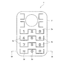
第1実施形態〔図1,図2〕: 第1実施形態によるキーシート1は、図1、図2で示すように、操作板2と樹脂フィルムでなるフィルムシート3とを備えている。
First Embodiment [FIGS. 1 and 2] : As shown in FIGS. 1 and 2, the
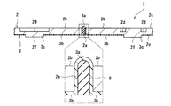
操作板2は硬質樹脂で形成された一枚板でなり、この一枚板には肉厚を貫通する仕切溝2aが角波状に設けられている。そして仕切溝2aで舌片状に仕切られた部分が押圧操作片2bとなっている。押圧操作片2bにおける操作面となる表面2cの中央には、文字、数字、記号、図形などを表す表示部2dが底面を有する凹状に形成されている。図1では、例えば記号「*」を表す表示部2dを設けた押圧操作片2bは、仕切溝2aで下向きに仕切られ、数字「0」を表す表示部2dを設けた押圧操作片2bは、仕切溝2aで上向きに仕切られている。押圧操作片2bにおける操作面とは反対の裏面2eの中央には、図外の接点スイッチを押圧する押し子部2fが設けられている。
The
フィルムシート3は熱可塑性樹脂で形成された一枚シートでなり、操作板2の裏面2eに図外の接着層で固着されている。このフィルムシート3には操作板2における仕切溝2aの溝内を裏面2e側から表面2c側に向かって膨出する突起3aが形成されており、この突起3aの先端は操作板2の表面2cより突出している。また、個々の押圧操作片2bの中央に相当する部位にはフィルムシート3に貫通孔3cが生じているが、操作板2の裏面2eから突出した押し子2fが該貫通孔3cを埋めている。
The
ここで、キーシート1を構成する各部材の材質を説明する。
Here, the material of each member constituting the
操作板2の材質は、剛性の高い材料が使用できる。剛性の高い材料として硬質樹脂があり、例えば、ポリカーボネート樹脂、ポリエステル樹脂、アクリル樹脂、ABS樹脂などが挙げられる。硬質樹脂以外では、ステンレス、アルミニウム、クロム、金、銀、銅、ニッケル、錫などの金属が挙げられる。なお操作板2の肉厚は50μm〜2000μmとすることができる。
As the material of the
フィルムシート3の材質は、柔軟性と耐摩耗性を兼ね備え突起形状を形成する樹脂フィルムなどの材料を使用することができる。例えば、ポリオレフィン系樹脂、ポリエステル系樹脂、ポリウレタン系樹脂、ポリアミド系樹脂などが挙げられる。フィルムシート3の肉厚は10μm〜200μmであれば破損することなく突起を形成できる。
As the material of the
次に本実施形態におけるキーシート1の製造方法の一例を説明する。
Next, an example of the manufacturing method of the
先ず射出成形にて硬質樹脂でなる操作板2を成形する。この時、射出成形金型のキャビティーによって肉厚を貫通する仕切溝2a及び底面を有する凹状の表示部2dを形成する。この操作板2の裏面2eにホットメルト接着剤でなる接着層を塗布する。次にフィルムシート3の成形用の金型に、操作板2の表面2cを金型面と接するようにインサートした後、貫通孔3cを形成したフィルムシート3を操作板2の裏面2eに載置して金型を閉じ、フィルムシート3を加熱エンボス成形する。この時、フィルムシート3には仕切溝2aの溝内に金型の突部で押し伸ばされた突起3aが形成され、操作板2の裏面2eとフィルムシート3が固着する。最後にフィルムシート3の外縁を操作板2の外縁と合わせて切り落としキーシート1を得ることができる。
First, the
次に本実施形態のキーシート1の作用効果について説明する。
Next, the effect of the
第1実施形態のキーシート1によれば、仕切溝2aを埋めるゴム状弾性体が露出する場合の不都合、すなわち、ゴム状弾性体の剥がれや切れを防ぐことができる。また、操作板2における仕切溝2aの溝内に爪や指先が入りにくくすることができる。繰り返される押圧操作によって、溝内のフィルムシート3による突起3aが削れることは生じにくく、薄型で安全なキーシート1を実現できる。
According to the
各突起3aが、一体物のフィルムシート3で構成されているため、製造時の取扱いが容易であり、操作板2との一体化を簡単にできる。
Since each
突起3aの先端が操作板2の表面2cより突出する形状であるため、仕切溝2aの位置を突起3aにて確認でき、押圧操作片2bの領域を指先の触感によって容易に識別できる。よって誤入力を防止できる。
Since the tip of the
操作板2の裏面2eとフィルムシート3を接着層で固着しているため、押圧操作を繰り返し行っても、操作板2とフィルムシート3の剥離を防ぐことができる。他方、操作板2における仕切溝2aの側面とフィルムシート3の突起3aを接着層で固着していないため、押圧操作の際に突起3a全体を変形させることができる。これに対し、操作板2の仕切溝2aにまでホットメルト接着剤を塗布することにより仕切溝2aの側面とフィルムシート3の突起3aを接着層で固着することができる。この場合は、押圧操作の際に突起3aの固着部分は変形せずに突起3aの先端のみが変形することになるため押圧荷重は大きくなる。
Since the
第1実施形態の第1変形例〔図3〕: 第1実施形態の第1変形例であるキーシート4を図3に示す。第1実施形態のキーシート1は突起3aの先端が操作板2の表面2cより突出する形状として例示したが、第1変形例のキーシート4では突起3aの先端と操作板2の表面2cとを面一に構成している。このようにすれば突起3aに対して指先などによる剪断方向の力がかからなくなり、指先などによる突起3aを変形し難くできる。
First Modification of First Embodiment [FIG. 3 ]: FIG. 3 shows a
第1実施形態の第2変形例〔図4〕: 第1実施形態の第2変形例であるキーシート5を図4に示す。第2変形例のキーシート5としては、突起3aの先端を操作板2の表面2cよりやや凹ませる構成にしている。この場合、第1変形例と同様に突起3aに対して指先などによる剪断方向の力がかからなくなり、指先などによる突起3aを変形を防ぐことができる。さらに仕切溝2aの凹みが小さく形成されていることによって、押圧操作片2bの領域を指先の触感によって容易に識別でき、誤入力を防止できるだけでなく、突起3aが全く無い場合に比べて爪や指先の引っかかりを少なくすることができる。
Second Modification of First Embodiment [FIG. 4] FIG. 4 shows a
第2実施形態〔図5〕: 第2実施形態のキーシート6を図5に示す。第2実施形態のキーシート6が、第1実施形態のキーシート1と異なるのは、キーシート6のフィルムシート3に設けた突起3aと操作板2に設けた仕切溝2aの側面との間に隙間tを形成している点である。
Second Embodiment [FIG. 5] : FIG. 5 shows a key sheet 6 of the second embodiment. The key sheet 6 of the second embodiment is different from the
第2実施形態におけるキーシート6の製造は、第1実施形態と同様に、射出成形にて操作板2を形成し、裏面2eに接着層を塗布する。そしてフィルムシート3の成形用の金型に操作板2をインサートするが、この金型には隙間tを形成するリブが設けてある。第1実施形態と同様に、フィルムシート3を載置して金型を閉じ、フィルムシート3を加熱エンボス成形した後、フィルムシート3の外縁を切り落としキーシート6を得ることができる。
In manufacturing the key sheet 6 in the second embodiment, as in the first embodiment, the
キーシート6では、突起3aと押圧操作片2bが隙間tによって離間しているため、押圧操作片2bを押圧した際に隙間tに相当するフィルムシート3の部分が屈曲し易く、突起3aの変形を小さくできる。よって突起3aを変形させる荷重が小さくなり、押圧操作片2bの押圧荷重を小さくできる。
In the key sheet 6, since the
第3実施形態〔図6〕: 第3実施形態のキーシート7を図6に示す。第3実施形態のキーシート7が、第1実施形態のキーシート1と異なるのは、突起3aの内部の構造である。
Third Embodiment [FIG. 6] : FIG. 6 shows a
キーシート7では、フィルムシート3における突起3aが形成する空間内をゴム状弾性体でなる中実部8が埋めている。
In the
中実部8を形成するゴム状弾性体の材質は、反撥性のよい熱硬化性エラストマー又は熱可塑性エラストマーが好ましい。例えば、シリコーンゴム、イソプレンゴム、エチレンプロピレンゴム、ブタジエンゴム、クロロプレンゴム、天然ゴム、スチレン系熱可塑性エラストマー、エステル系熱可塑性エラストマー、ウレタン系熱可塑性エラストマー、オレフィン系熱可塑性エラストマー、アミド系熱可塑性エラストマー、ブタジエン系熱可塑性エラストマー、エチレン−酢酸ビニル系熱可塑性エラストマー、フッ素系熱可塑性エラストマー、イソプレン系熱可塑性エラストマー、塩素化ポリエチレン系熱可塑性エラストマー等が挙げられる。さらにこれらのゴム状弾性体で温度依存性が少ない点を考慮するとシリコーンゴムが好ましく、また耐久性を考慮するとスチレン系熱可塑性エラストマー、エステル系熱可塑性エラストマーが好ましい。 The material of the rubber-like elastic body forming the solid portion 8 is preferably a thermosetting elastomer or a thermoplastic elastomer with good rebound. For example, silicone rubber, isoprene rubber, ethylene propylene rubber, butadiene rubber, chloroprene rubber, natural rubber, styrene thermoplastic elastomer, ester thermoplastic elastomer, urethane thermoplastic elastomer, olefin thermoplastic elastomer, amide thermoplastic elastomer Butadiene-based thermoplastic elastomer, ethylene-vinyl acetate-based thermoplastic elastomer, fluorine-based thermoplastic elastomer, isoprene-based thermoplastic elastomer, chlorinated polyethylene-based thermoplastic elastomer, and the like. Further, silicone rubber is preferable in view of the low temperature dependence of these rubber-like elastic bodies, and styrene-based thermoplastic elastomers and ester-based thermoplastic elastomers are preferable in consideration of durability.
また、本実施形態のフィルムシート3は、形状保持力が乏しいか、または全く無い腰の弱いフィルムとすることができる。中実部8をなすゴム状弾性体が突起3aの形状を保持しうるからである。
Moreover, the
第3実施形態におけるキーシート7の製造は、第1実施形態と同様に、射出成形にて操作板2を形成し、裏面2eに接着層を塗布する。そしてフィルムシート3の成形用の金型に操作板2をインサートした後、フィルムシート3を載置して金型を閉じ、フィルムシート3を加熱エンボス成形して操作板2とフィルムシート3を一体にする。その後フィルムシート3の外縁を切り落とす。最後に中実部8の成形用の金型に、操作板2の表面2cを金型面と接するようにインサートしたのちに金型を閉じ、ピンゲートにて突起3aの空間内にゴム状弾性体を注入し中実部8を成形する。こうして、キーシート7を得ることができる。なお本実施形態の製造方法では、フィルムシート3に突起3aを形成した後、突起3aの空間内にゴム状弾性体を注入して中実部8を成形しているが、予め突起3aを形成せずにゴム状弾性体の注入と同時に突起3aと中実部8を形成する方法も可能である。
In manufacturing the
キーシート7では、ゴム状弾性体でなる中実部8をフィルムシート3で覆うように突起3aが形成されるため、ゴム状弾性体でなる中実部8の剥がれや切れが生じにくい。また、突起3aの内部が中実であるので押圧操作の際に突起3aを指先などで押圧しても中実部8が突起3aの内部から反撥して突起3aが凹むことを防止できる。なお、中実部8を突起3aの先端付近の一部にのみ備え、突起3aの内部全体を埋めないように構成しても、同様に突起3aの凹みを防止できる。
In the
第3実施形態の変形例〔図7〕: 第3実施形態の変形例のキーシート9を図7に示す。第3実施形態のキーシート7では中実部8を突起3aが形成する空間内に備えてものとして例示したが、変形例のキーシート9では図外の基板に向けて押し子部2fの突出方向と同一方向に中実部8をフィルムシート3より突出させることができる。このようにすれば中実部8の突出部分をキーシート9の脚部10として基板面に接触させることができる。このため押圧操作の際に、基板面に当接する脚部10が隣接する押圧操作片2bの連動を防ぎ、誤入力を防止できる。
Modified Example of Third Embodiment [FIG. 7] FIG. 7 shows a key sheet 9 of a modified example of the third embodiment. In the
第4実施形態〔図8〕: 第4実施形態のキーシート11を図8に示す。第4実施形態のキーシート11は、フィルムシート3の裏面にベースシート12を備えている。
Fourth Embodiment [FIG. 8] : FIG. 8 shows a
ベースシート12は薄肉のゴム状弾性体でなり、フィルムシート3における操作板2との対向面とは反対の裏面に固着されている。このベースシート12は、突出部12a、ベース部12b、押し子部12cから構成されている。このうち突出部12aは、「中実部」としてフィルムシート3における突起3aの空間内を埋めるように形成されている。ベース部12bは複数の突出部12aを一体に繋ぐ部分であり、このベース部12bには押圧操作片2bごとに図外の接点スイッチを押圧する押し子部12cが設けられている。
The
操作板2は裏面2eが平坦であり、前述の実施形態で設けられていた押し子部2fを無くしてある。またフィルムシート3には、前述の実施形態で形成されていた貫通孔3cを無くしてある。
The
第4実施形態におけるキーシート11の製造は、第3実施形態と同様に、射出成形にて操作板2を形成する。そして操作板2の裏面2eに瞬間接着剤や紫外線硬化接着剤を塗布し、フィルムシート3を載置して操作板2とフィルムシート3を接着し一体にする。その後フィルムシート3の外縁を切り落とす。最後にベースシート12の成形用の金型に、操作板2の表面2cを金型面と接するようにインサートした後、フィルムシート3の上にゴム状弾性体を載置し金型を閉じてコンプレッション成形にてベースシート12を形成する。この時、ゴム状弾性体の圧力を受けてフィルムシート3に突起3aが形成され、同時にこの突起3a内に中実部8が成形される。これによってキーシート11を得ることができる。
In the manufacture of the
キーシート11では、突出部12aを有するベースシート12を備えるため、フィルムシート3の各突起3aごとに「中実部」を形成する必要がない。よって製造が容易であり、フィルムシート3との一体化を簡単にできる。
Since the
第4実施形態の第1変形例〔図9〕: 第4実施形態の第1変形例のキーシート13を図9に示す。第4実施形態のキーシート11は、押圧操作片2bの表示部2dを底面を有する凹状の形状として例示したが、第1変形例のキーシート13では、この表示部2dを貫通孔にして、フィルムシート3の全裏面にEL層14を備える構成としている。この場合、EL層14を発光させれば表示部2d及び仕切溝2aが照光され、暗所でも見やすい操作板2を実現できる。なお、EL層14を押圧操作片2bの裏面側にのみ設け仕切溝2a内に設けなければ、表示部2dのみ照光する操作板2を実現でき、さらに押圧操作片2bごとに照光色を変えることや、特定の押圧操作片2bのみ発光させてガイド機能を付加することもできる。なお、EL層14は両電極と発光層、絶縁層(誘電層)などが積層した構成でなり電界が印加されて発光する性質を有する。
First Modification of Fourth Embodiment [FIG. 9] : FIG. 9 shows a
第4実施形態の第2変形例〔図10〕: 第4実施形態の第2変形例のキーシート15を図10に示す。第2変形例のキーシート15としては、ベースシート12のうち隣接する押圧操作片2bどうしの間のベース部12bに図外の基板に向けて凹部12dを設ける構成としたものである。この場合、第2変形例のキーシート15では、押圧操作片2bの間のベース部12bに薄肉部分を形成するため、押圧操作片2bを押圧した際にベース部12bを変形し易くでき、押圧操作片2bの押圧荷重を小さくできる。
Second Modification of Fourth Embodiment [FIG. 10] : FIG. 10 shows a
第1実施形態〜第4実施形態の変形例〔図11〕: 第1実施形態〜第4実施形態およびその変形例で示したキーシート1、4〜7,9,11,13,15についてはさらに以下のような変更が可能である。
Modified Example of First to Fourth Embodiments (FIG. 11) : For the
図11で示すキーシート16は、環状の仕切溝2aを設け、押圧操作片2bの全周を仕切溝2aで仕切るように変更したものである。操作板2には環状の仕切溝2aを形成してあり、「分割する押圧操作片」としての分割板2gを備えている。具体的には数字「5」を表す表示部2dを設けた押圧操作片を分割板2gとしている。この分割板2gは、環状の仕切溝2aの溝内に備わっているフィルムシート3における環状の突起3aによって操作板2と一体に繋がっている。
The
キーシート16では、操作板2と分割板2gを備えるため、斬新なデザインを実現できる。またフィルムシート3の突起3aが押圧によって変形する荷重は、操作板2の板部分が押圧によって屈曲する荷重より小さいことから、環状の突起3aに囲まれている分割板2gは、三方向を突起3aで囲まれている押圧操作片2bに比べて押圧荷重を小さくすることができる。
Since the
また、各実施形態における特徴的な構成は、他の実施形態についても適用することができる。その一例としては、前述の第1〜第3実施形態の表示部2dを貫通孔にしてフィルムシート3にEL層14を設けることも可能である。別な例としては、前述の第2実施形態の突起3aの空間内に中実部8を備えることも可能である。さらに別な例としては、前述の第3,第4実施形態の中実部8を柱形状にして操作板2の面方向に間隔を空けて点在させることも可能である。
In addition, the characteristic configuration in each embodiment can be applied to other embodiments. As an example, the
以上の実施形態については、仕切溝2aを角波状の形状として例示したが、丸波状の形状としてもよい。また仕切溝2aの縁形状も直線状に加え、曲線状、波状の形状としてもよい。
In the above embodiment, the
以上の実施形態では、操作板2の表面2cに表示部2dを形成したが、操作板2を透明材で形成し操作板2の裏面2eに凹形状や印刷層による表示部2dを設けてもよい。
In the above embodiment, the
さらに以上の各実施形態では、フィルムシート3の突起3aを操作板2における仕切溝2aの溝内にのみ備えている例を示したが、操作板2の表示部2dを貫通孔に形成しフィルムシート3の突起3aを仕切溝2aの溝内に加えて表示部2dの孔内にも備えることができる。このようにすれば、仕切溝2aに加えて表示部2dも突起3aにて確認でき、押圧操作片2bの領域及び表示部2dの形状を触感によって識別できる。このため誤入力を防止できる。
Further, in each of the above-described embodiments, the example in which the
また以上の各実施形態の製造では、射出成形にて操作板2を成形する例を示したが、押出成形で樹脂板を成形した後、この樹脂板に抜き加工や切削加工を用いて仕切溝2aや表示部2bを形成し操作板2を製造することも可能である。
Further, in the manufacture of each of the above embodiments, an example in which the
1 キーシート(第1実施形態)
2 操作板
2a 仕切溝
2b 押圧操作片
2c 表面
2d 表示部
2e 裏面
2f 押し子部
2g 分割板
3 フィルムシート
3a 突起
3b 連結部
3c 貫通孔
4 キーシート(第1実施形態の第1変形例)
5 キーシート(第1実施形態の第2変形例)
6 キーシート(第2実施形態)
7 キーシート(第3実施形態)
8 中実部
9 キーシート(第3実施形態の変形例)
10 脚部
11 キーシート(第4実施形態)
12 ベースシート
12a 突出部
12b ベース部
12c 押し子部
12d 凹部
13 キーシート(第4実施形態の第1変形例)
14 EL層
15 キーシート(第4実施形態の第2変形例)
16 キーシート(第1〜第4実施形態の変更例1)
t 隙間
1 Key sheet (first embodiment)
2
5 Key sheet (second modification of the first embodiment)
6 Key sheet (second embodiment)
7 Key sheet (Third embodiment)
8 Solid part 9 Key sheet (Modification of the third embodiment)
10
12
14
16 Key sheet (
t clearance
Claims (21)
該操作板の操作面とは反対の裏面に設けるフィルムシートと、を備え、
該フィルムシートに、操作板の裏面から仕切溝に向かって膨出する突起を設け、
突起の内部が空間であるキーシート。 An operation plate provided with a partition groove for forming a pressing operation piece capable of being pressed and displaced;
A film sheet provided on the back surface opposite to the operation surface of the operation plate,
Providing the film sheet with a protrusion that bulges from the back surface of the operation plate toward the partition groove ,
A key sheet in which the protrusion is a space .
該操作板の操作面とは反対の裏面に設けるフィルムシートと、を備え、
該フィルムシートに、操作板の裏面から仕切溝に向かって膨出する突起を設け、
突起と仕切溝の側面との間に隙間を有するキーシート。 An operation plate provided with a partition groove for forming a pressing operation piece capable of being pressed and displaced;
A film sheet provided on the back surface opposite to the operation surface of the operation plate,
Providing the film sheet with a protrusion that bulges from the back surface of the operation plate toward the partition groove ,
A key sheet having a gap between the protrusion and the side surface of the partition groove .
該操作板の操作面とは反対の裏面に設けるフィルムシートと、
フィルムシートの裏面側に設けるゴム状弾性体でなるベースシートと、を備え、
該フィルムシートに、操作板の裏面から仕切溝に向かって膨出する突起を設け、
隣接する押圧操作片どうしの間のベースシートに凹部を有するキーシート。 An operation plate provided with a partition groove for forming a pressing operation piece capable of being pressed and displaced;
A film sheet provided on the back surface opposite to the operation surface of the operation plate;
A base sheet made of a rubber-like elastic body provided on the back side of the film sheet ,
Providing the film sheet with a protrusion that bulges from the back surface of the operation plate toward the partition groove ,
A key sheet having a recess in a base sheet between adjacent pressing operation pieces .
該操作板の操作面とは反対の裏面に設けるフィルムシートと、
フィルムシートの裏面側に設けた発光可能なEL層と、を備え、
該フィルムシートに、操作板の裏面から仕切溝に向かって膨出する突起を設け、
突起が前記EL層を含んで構成されるキーシート。 An operation plate provided with a partition groove for forming a pressing operation piece capable of being pressed and displaced;
A film sheet provided on the back surface opposite to the operation surface of the operation plate;
An EL layer capable of emitting light provided on the back side of the film sheet ,
Providing the film sheet with a protrusion that bulges from the back surface of the operation plate toward the partition groove,
A key sheet in which a protrusion includes the EL layer .
請求項1〜4何れか1項記載のキーシート。 The key sheet according to any one of claims 1 to 4 , wherein the operation plate is a single plate-like resin plate.
請求項1〜4何れか1項記載のキーシート。 The key sheet according to any one of claims 1 to 4 , wherein the operation plate is a single-plate metal thin plate.
請求項2〜6何れか1項記載のキーシート。 The key sheet according to claim 2 , wherein the inside of the protrusion is a space.
請求項2〜6何れか1項記載のキーシート。 The key sheet according to any one of claims 2 to 6 , wherein the inside of the protrusion is a solid part made of a rubber-like elastic body.
請求項3〜8何れか1項記載のキーシート。 The key sheet according to claim 3 , wherein a gap is provided between the protrusion and the side surface of the partition groove.
請求項1〜9何れか1項記載のキーシート。 Key sheet according to claim 1 to 9 any one of claims protrusion protrudes from the operating surface of the operation plate.
請求項1〜9何れか1項記載のキーシート。 The key sheet according to any one of claims 1 to 9 , wherein the protrusion is recessed from the operation surface of the operation plate.
請求項8記載のキーシート。 The key sheet according to claim 8 , wherein the solid part protrudes from the film sheet in a reverse direction opposite to the operation surface of the operation plate.
請求項8または12記載のキーシート。 The key sheet according to claim 8 or 12 , wherein the solid portions are columnar and are scattered at intervals in the surface direction of the operation plate.
請求項1,2,4〜7何れか1項記載のキーシート。 The key sheet according to claim 1 , further comprising a base sheet made of a rubber-like elastic body on a back surface of the film sheet.
請求項8〜13何れか1項記載のキーシート。The key sheet according to any one of claims 8 to 13.
請求項15記載のキーシート。 The key sheet according to claim 15 , wherein the solid part and the base sheet are integrally formed.
請求項14〜16何れか1項記載のキーシート。 The key sheet according to any one of claims 14 to 16 , wherein the base sheet between adjacent pressing operation pieces has a recess.
請求項1〜3,5〜17何れか1項記載のキーシート。 The key sheet according to any one of claims 1 to 3, 5 to 17, further comprising an EL layer capable of emitting light on a back surface side of the film sheet.
請求項18記載のキーシート。 The key sheet according to claim 18 , wherein the protrusion includes the EL layer.
請求項1〜19何れか1項記載のキーシート。 Key sheet according to claim 1 to 19 any one of claims with a depressing operation member defined by the annular partition groove.
フィルムシートに操作板の裏面から該貫通孔に向かって膨出する突起をさらに設けるThe film sheet is further provided with a protrusion that bulges from the back surface of the operation plate toward the through hole.
請求項1〜20何れか1項記載のキーシート。The key sheet according to claim 1.
Priority Applications (4)
| Application Number | Priority Date | Filing Date | Title |
|---|---|---|---|
| JP2006117236A JP4151849B2 (en) | 2006-04-20 | 2006-04-20 | Key sheet |
| CN2007100884905A CN101060042B (en) | 2006-04-20 | 2007-03-27 | Key sheet |
| EP07007029A EP1848018A3 (en) | 2006-04-20 | 2007-04-04 | Key sheet |
| US11/785,462 US7737375B2 (en) | 2006-04-20 | 2007-04-18 | Key sheet |
Applications Claiming Priority (1)
| Application Number | Priority Date | Filing Date | Title |
|---|---|---|---|
| JP2006117236A JP4151849B2 (en) | 2006-04-20 | 2006-04-20 | Key sheet |
Related Child Applications (1)
| Application Number | Title | Priority Date | Filing Date |
|---|---|---|---|
| JP2008111446A Division JP4843639B2 (en) | 2008-04-22 | 2008-04-22 | Key sheet |
Publications (3)
| Publication Number | Publication Date |
|---|---|
| JP2007294114A JP2007294114A (en) | 2007-11-08 |
| JP2007294114A5 JP2007294114A5 (en) | 2008-03-13 |
| JP4151849B2 true JP4151849B2 (en) | 2008-09-17 |
Family
ID=38109617
Family Applications (1)
| Application Number | Title | Priority Date | Filing Date |
|---|---|---|---|
| JP2006117236A Expired - Fee Related JP4151849B2 (en) | 2006-04-20 | 2006-04-20 | Key sheet |
Country Status (4)
| Country | Link |
|---|---|
| US (1) | US7737375B2 (en) |
| EP (1) | EP1848018A3 (en) |
| JP (1) | JP4151849B2 (en) |
| CN (1) | CN101060042B (en) |
Families Citing this family (6)
| Publication number | Priority date | Publication date | Assignee | Title |
|---|---|---|---|---|
| EP1717834B1 (en) * | 2005-04-28 | 2011-10-12 | Polymatech Co., Ltd. | Pushbutton switch cover sheet and method of manufacturing the same |
| JP4190568B1 (en) * | 2007-07-30 | 2008-12-03 | シャープ株式会社 | Mobile device |
| KR101486342B1 (en) * | 2008-02-27 | 2015-01-26 | 엘지전자 주식회사 | Button assembly and Laundry machine having the same |
| CN101777454A (en) * | 2009-01-13 | 2010-07-14 | 深圳富泰宏精密工业有限公司 | Key panel and making method thereof |
| US8224391B2 (en) * | 2009-07-20 | 2012-07-17 | Lg Electronics Inc. | Mobile terminal having an LED backlight unit |
| TW201842008A (en) * | 2017-03-15 | 2018-12-01 | 日商住友電木股份有限公司 | Resin sheet, laminate resin sheet, and resin composition |
Family Cites Families (23)
| Publication number | Priority date | Publication date | Assignee | Title |
|---|---|---|---|---|
| US4258096A (en) * | 1978-11-09 | 1981-03-24 | Sheldahl, Inc. | Composite top membrane for flat panel switch arrays |
| JP3211127B2 (en) | 1994-06-23 | 2001-09-25 | 帝国通信工業株式会社 | Key top plate for push button switch |
| JP3368428B2 (en) | 1994-10-13 | 2003-01-20 | 帝国通信工業株式会社 | Key top plate |
| JP3151553B2 (en) * | 1996-11-29 | 2001-04-03 | 帝国通信工業株式会社 | Key top plate and manufacturing method thereof |
| US6326569B1 (en) * | 1998-03-31 | 2001-12-04 | Key Plastics, Inc. | Control panel assembly and method of making same |
| KR100342959B1 (en) | 1998-12-31 | 2002-07-05 | 양윤홍 | Keypad for cellular phone and method of manufacturing same |
| JP4069572B2 (en) | 2000-03-31 | 2008-04-02 | 松下電器産業株式会社 | Pushbutton switch, manufacturing method thereof, and composite switch using the same |
| MXPA04010251A (en) * | 2002-05-23 | 2005-06-08 | Digit Wireless Llc | Keypads and key switches. |
| JP4119707B2 (en) | 2002-08-02 | 2008-07-16 | ポリマテック株式会社 | Keypad, injection mold for resin key top, and method for manufacturing resin key top |
| JP4113784B2 (en) | 2003-01-21 | 2008-07-09 | 信越ポリマー株式会社 | Pushbutton switch member and manufacturing method thereof |
| JP2004311127A (en) | 2003-04-03 | 2004-11-04 | Alps Electric Co Ltd | Contact spring and switching device using this |
| JP4435507B2 (en) | 2003-06-03 | 2010-03-17 | ポリマテック株式会社 | Key sheet |
| KR20050031670A (en) | 2003-09-30 | 2005-04-06 | 삼성전기주식회사 | Key switch device and manufacturing method thereof |
| US7345250B2 (en) * | 2003-10-23 | 2008-03-18 | Nokia Corporation | Keyboard with key supporting structure for portable electronics devices |
| JP4241322B2 (en) | 2003-10-30 | 2009-03-18 | 東邦亜鉛株式会社 | Partition wall |
| KR100640388B1 (en) * | 2004-04-14 | 2006-10-30 | 삼성전자주식회사 | Portable telephone with touch key |
| US7070349B2 (en) * | 2004-06-18 | 2006-07-04 | Motorola, Inc. | Thin keyboard and components for electronics devices and methods |
| JP4679226B2 (en) | 2004-10-28 | 2011-04-27 | ポリマテック株式会社 | Cover sheet for pushbutton switch |
| JP2006209989A (en) | 2005-01-25 | 2006-08-10 | Sunarrow Ltd | Key sheet with reinforcing plate and manufacturing method thereof |
| TWI269332B (en) * | 2005-06-29 | 2006-12-21 | Speed Tech Corp | Keypad and manufacturing method thereof |
| JP4728771B2 (en) | 2005-10-24 | 2011-07-20 | サンアロー株式会社 | Key sheet |
| JP4594880B2 (en) | 2006-03-02 | 2010-12-08 | 信越ポリマー株式会社 | Pushbutton switch member and manufacturing method thereof |
| JP4398951B2 (en) * | 2006-04-03 | 2010-01-13 | ポリマテック株式会社 | Key sheet |
-
2006
- 2006-04-20 JP JP2006117236A patent/JP4151849B2/en not_active Expired - Fee Related
-
2007
- 2007-03-27 CN CN2007100884905A patent/CN101060042B/en not_active Expired - Fee Related
- 2007-04-04 EP EP07007029A patent/EP1848018A3/en not_active Withdrawn
- 2007-04-18 US US11/785,462 patent/US7737375B2/en not_active Expired - Fee Related
Also Published As
| Publication number | Publication date |
|---|---|
| US7737375B2 (en) | 2010-06-15 |
| CN101060042B (en) | 2012-03-28 |
| US20070246342A1 (en) | 2007-10-25 |
| EP1848018A2 (en) | 2007-10-24 |
| EP1848018A3 (en) | 2009-04-22 |
| CN101060042A (en) | 2007-10-24 |
| JP2007294114A (en) | 2007-11-08 |
Similar Documents
| Publication | Publication Date | Title |
|---|---|---|
| KR101283216B1 (en) | Thin keypad assemblies and components for electronics devices and methods | |
| JP4151849B2 (en) | Key sheet | |
| JP4820405B2 (en) | Pushbutton switch member and manufacturing method thereof | |
| JP4473752B2 (en) | Cover sheet for pushbutton switch | |
| EP1717834B1 (en) | Pushbutton switch cover sheet and method of manufacturing the same | |
| US8362381B2 (en) | Switch mechanism and electronic device | |
| JP4679226B2 (en) | Cover sheet for pushbutton switch | |
| JP4146866B2 (en) | Pushbutton switch member and manufacturing method thereof | |
| KR100979588B1 (en) | Member for push button switch and method of manufacturing the same | |
| JP4282656B2 (en) | Pushbutton switch member and manufacturing method thereof | |
| JP2008204871A (en) | Decorative key sheet for push-button switch | |
| JP5273139B2 (en) | Switch mechanism and electronic equipment | |
| JP4594880B2 (en) | Pushbutton switch member and manufacturing method thereof | |
| JP4843639B2 (en) | Key sheet | |
| CN212625301U (en) | Member for push-button switch | |
| JP2009146642A (en) | Key sheet | |
| US9064652B2 (en) | Electrical switch, of the normally-closed type, especially for a portable communication device | |
| KR100795893B1 (en) | Keypad for the computer | |
| JP2016184565A (en) | Push button switch and manufacturing method of the same | |
| WO2004112069A1 (en) | Key unit and method for manufacturing the same | |
| JP2011204419A (en) | Member for input sheet and its manufacturing method |
Legal Events
| Date | Code | Title | Description |
|---|---|---|---|
| A521 | Request for written amendment filed |
Free format text: JAPANESE INTERMEDIATE CODE: A523 Effective date: 20080128 |
|
| A621 | Written request for application examination |
Free format text: JAPANESE INTERMEDIATE CODE: A621 Effective date: 20080128 |
|
| A871 | Explanation of circumstances concerning accelerated examination |
Free format text: JAPANESE INTERMEDIATE CODE: A871 Effective date: 20080128 |
|
| A975 | Report on accelerated examination |
Free format text: JAPANESE INTERMEDIATE CODE: A971005 Effective date: 20080213 |
|
| A131 | Notification of reasons for refusal |
Free format text: JAPANESE INTERMEDIATE CODE: A131 Effective date: 20080222 |
|
| A521 | Request for written amendment filed |
Free format text: JAPANESE INTERMEDIATE CODE: A523 Effective date: 20080422 |
|
| TRDD | Decision of grant or rejection written | ||
| A01 | Written decision to grant a patent or to grant a registration (utility model) |
Free format text: JAPANESE INTERMEDIATE CODE: A01 Effective date: 20080530 |
|
| A01 | Written decision to grant a patent or to grant a registration (utility model) |
Free format text: JAPANESE INTERMEDIATE CODE: A01 |
|
| A61 | First payment of annual fees (during grant procedure) |
Free format text: JAPANESE INTERMEDIATE CODE: A61 Effective date: 20080626 |
|
| R150 | Certificate of patent or registration of utility model |
Free format text: JAPANESE INTERMEDIATE CODE: R150 Ref document number: 4151849 Country of ref document: JP Free format text: JAPANESE INTERMEDIATE CODE: R150 |
|
| FPAY | Renewal fee payment (event date is renewal date of database) |
Free format text: PAYMENT UNTIL: 20110711 Year of fee payment: 3 |
|
| FPAY | Renewal fee payment (event date is renewal date of database) |
Free format text: PAYMENT UNTIL: 20120711 Year of fee payment: 4 |
|
| R250 | Receipt of annual fees |
Free format text: JAPANESE INTERMEDIATE CODE: R250 |
|
| FPAY | Renewal fee payment (event date is renewal date of database) |
Free format text: PAYMENT UNTIL: 20130711 Year of fee payment: 5 |
|
| R250 | Receipt of annual fees |
Free format text: JAPANESE INTERMEDIATE CODE: R250 |
|
| R250 | Receipt of annual fees |
Free format text: JAPANESE INTERMEDIATE CODE: R250 |
|
| R250 | Receipt of annual fees |
Free format text: JAPANESE INTERMEDIATE CODE: R250 |
|
| S111 | Request for change of ownership or part of ownership |
Free format text: JAPANESE INTERMEDIATE CODE: R313111 |
|
| R350 | Written notification of registration of transfer |
Free format text: JAPANESE INTERMEDIATE CODE: R350 |
|
| R250 | Receipt of annual fees |
Free format text: JAPANESE INTERMEDIATE CODE: R250 |
|
| R250 | Receipt of annual fees |
Free format text: JAPANESE INTERMEDIATE CODE: R250 |
|
| R250 | Receipt of annual fees |
Free format text: JAPANESE INTERMEDIATE CODE: R250 |
|
| S533 | Written request for registration of change of name |
Free format text: JAPANESE INTERMEDIATE CODE: R313533 |
|
| R350 | Written notification of registration of transfer |
Free format text: JAPANESE INTERMEDIATE CODE: R350 |
|
| R250 | Receipt of annual fees |
Free format text: JAPANESE INTERMEDIATE CODE: R250 |
|
| R250 | Receipt of annual fees |
Free format text: JAPANESE INTERMEDIATE CODE: R250 |
|
| LAPS | Cancellation because of no payment of annual fees |