JP4149213B2 - Pointed position detection device and autonomous robot - Google Patents
Pointed position detection device and autonomous robot Download PDFInfo
- Publication number
- JP4149213B2 JP4149213B2 JP2002231899A JP2002231899A JP4149213B2 JP 4149213 B2 JP4149213 B2 JP 4149213B2 JP 2002231899 A JP2002231899 A JP 2002231899A JP 2002231899 A JP2002231899 A JP 2002231899A JP 4149213 B2 JP4149213 B2 JP 4149213B2
- Authority
- JP
- Japan
- Prior art keywords
- hand
- person
- detected
- indicated
- position detection
- Prior art date
- Legal status (The legal status is an assumption and is not a legal conclusion. Google has not performed a legal analysis and makes no representation as to the accuracy of the status listed.)
- Expired - Fee Related
Links
Images


Classifications
-
- G—PHYSICS
- G06—COMPUTING; CALCULATING OR COUNTING
- G06T—IMAGE DATA PROCESSING OR GENERATION, IN GENERAL
- G06T7/00—Image analysis
- G06T7/70—Determining position or orientation of objects or cameras
- G06T7/73—Determining position or orientation of objects or cameras using feature-based methods
Landscapes
- Engineering & Computer Science (AREA)
- Computer Vision & Pattern Recognition (AREA)
- Physics & Mathematics (AREA)
- General Physics & Mathematics (AREA)
- Theoretical Computer Science (AREA)
- Image Analysis (AREA)
- Manipulator (AREA)
- Closed-Circuit Television Systems (AREA)
- Image Processing (AREA)
Description
【0001】
【発明の属する技術分野】
本発明は、画像を使用して人間の姿勢を認識することにより人間が出す指示位置を検出する指示位置検出装置及び自律ロボットに関する。
【0002】
【従来の技術】
従来から人間が発する音声指示を音声認識することにより、自己に対する指示を認識して行動を起こす自律ロボットが知られている。これは、自律ロボットに対して指示する場合において、指示する者は特別な装置を用いることなく指示を与えることができるという特徴を有している。
ところで、音声による指示系統は、騒音が多い場所では音声認識率が低下するため、指示を正確に伝達することができないという問題を有している。さらに、音声認識は、認識率を向上させるためには音声を発する人物の音声を予め登録する必要があり、誰でも指示を与えることができるわけではない。
【0003】
このような問題を解決するために、画像情報を用いて人物の身体姿勢を認識し、その姿勢が意味する指示を認識する手法が試みられている。例えば、電気学会論文誌C 電子・情報・システム部門誌Vol.121-C(2001.9)p1388-p1394「マルチカメラを用いた全方位ポインティングジェスチャの方向推定」(以下、先行技術1と称する)に記載されたポインティングジェスチャの方向推定方法が知られている。この方法は、まず、複数のカメラで人物を撮影し得られた画像から顔領域抽出を行い、顔向き推定結果に基づき正面顔を検出し、さらに眼部位置を特定する。次に、得られた画像から手領域抽出を行い、この手領域の端部を指先位置として特定する。そして、ここで得られた眼部と指先の空間位置を求め、この2点を結んだ延長線上をポインティング方向として推定するものである。また、電気学会論文誌C 電子・情報・システム部門誌Vol.121-C(2001.9)p1464-p1470「実空間にマークを投影するインタラクティブハンドポインタの構成」(以下、先行技術2と称する)に記載されたインタラクティブハンドポインタの方法が知られている。この方法は、単純な背景下において指示を出す人物の手をカメラで撮影し得られた画像と予め用意された指先のテンプレート画像とのブロックマッチングによって得られた指先位置と、この位置から一定領域内にある指の付け根の中心位置とを結ぶ直線を指差し方向とするものである。
これらの方法によれば、指示を出す人物の指先が指している方向の物体を認識して、ロボットが次の動作を起こすなどのヒューマン・ロボットインタフェースとして利用可能である。
【0004】
【発明が解決しようとする課題】
しかしながら、先行技術1のように、頭と手先を結ぶ仮想の直線の延長線に基づいて指示位置とする方法は、指示対象までの距離が長くなるにしたがって検出位置の偏差が大きくなり、この偏差を小さくするためには特別な指示方法をしなければならないという問題がある。また、この方法は、画像から抽出した手領域の重心位置から最も離れた点を指先位置としているため、腕を曲げて指示をすると全く異なった位置を示したものと認識されてしまうという問題がある。
また、先行技術2にように、単純背景下において指先とその向きを検出する方法は、既知の背景である必要があるとともに、カメラの設置場所についても制限があるという問題がある。また、この方法は検出範囲が狭く近距離の位置を指差す以外は偏差が大きくなるという問題がある。
【0005】
本発明は、このような事情に鑑みてなされたもので、自然な状態で指示動作をすることができ、かつ精度の高い指示位置検出を行うことが可能な指示位置検出装置及び指示位置検出結果に基づいて行動を起こす自律ロボットを提供することを目的とする。
【0006】
【課題を解決するための手段】
請求項1に記載の発明は、複数のカメラで撮影した画像から人物を検出し、該人物が指示する位置を検出する指示位置検出装置において、前記画像に基づいて少なくとも距離情報を含む前記人物の頭部位置を検出する手段と、前記画像に基づいて少なくとも距離情報を含む前記人物の手の位置を検出する手段と、前記検出された手の位置に基づいて手先の位置および手の向きを算出する手段と、前記検出された頭部位置と前記検出された手先の位置及び手の向きに基づいて、人物が指示する方向を検出する手段を備え、前記検出された人物が指示する方向に基づいて指示する位置を検出するようにしたことを特徴とする。
この構成によれば、距離情報を含む手の位置から手の向きと手先位置を検出するともに、距離情報を含む人物の頭の位置を検出し、検出された頭部位置と手先の位置と手の向きに基づいて、人物が指示する方向を検出するようにし、この方向から指示する位置を検出するようにしたため、精度良く指示位置を検出することができる。また、手の向きに基づいて指示位置を検出するようにしたため、腕を曲げても精度良く指示位置の検出が可能となる。さらに、距離情報を含む位置に基づいて指示位置を検出するようにしたため、検出時のカメラの設置位置や背景の制限を無くすことができる。
【0007】
請求項2に記載の発明は、前記検出された頭部位置に基づいて目の位置を算出する手段をさらに備え、前記人物が指示する方向を検出する手段は、前記目の位置と手先の位置及び手の向きに基づいて人物が指示する方向を検出することを特徴とする。
この構成によれば、目の位置と手先の位置と手の向きに基づいて人物が指示する方向を検出するようにしたため、人物が指示する位置をさらに高精度に検出することができる。
【0008】
請求項3に記載の発明は、前記手の位置を検出する手段は、前記手の位置に基づいて画像中に所定の探索領域を設定する手段をさらに備えたことを特徴とする。
この構成によれば、手の位置に基づいて画像中に所定の探索領域を設定するようにしたため、手先の位置及び手の向きを検出する速度を向上することができる。
【0009】
請求項4に記載の発明は、前記探索領域内に存在する手を構成する画素データの分布に基づいて手の向きを検出するようにしたことを特徴とする。
この構成によれば、探索領域内に存在する手を構成する画素データの分布に基づいて手の向きを検出するようにしたため、複雑な処理を用いることなく演算のみによって手の向きを検出することができる。
【0010】
請求項5に記載の発明は、前記検出された人物が指示する方向と画像中に存在する所定の物体との交点を算出し、指示する位置を検出することを特徴とする。
この構成によれば、検出された人物が指示する方向と画像中に存在する所定の物体との交点を算出し、指示する位置を検出するようにしたため、床や壁などを指差した場合においても簡単な演算で位置の検出をすることができる。
【0011】
請求項6に記載の発明は、自律ロボットに請求項1ないし5のいずれかに記載の指示位置検出装置を備えたことを特徴とする。
この構成によれば、指示位置を高精度に検出することができる指示位置検出装置を自律ロボットに備えたため、高度なヒューマン・ロボットインタフェースを実現することができる。
【0012】
【発明の実施の形態】
以下、本発明の一実施形態による指示位置検出装置及び自律ロボットを図面を参照して説明する。図1は同実施形態の構成を示すブロック図である。符号1は、2台のカラーCCDを用いたステレオカメラ(以下、単にカメラと称する)である。符号2は、カメラ1で得られた画像に基づいて人物の指示を認識する指示位置検出部である。符号3は、人物が発する音声を集音するマイクである。符号4は、マイク3で集音した音声を認識する音声認識部である。符号5は、指示位置検出部2における指示位置検出結果に基づいて、自己(自律ロボット)の行動を起こすための処理を行う応答処理部である。符号6は、応答処理部5の出力に基づいて自律ロボットの動作(脚、頭部、腕等を動かす)を制御する行動制御部である。
【0013】
符号21は、カメラ1で得られた画像に対して、後の処理を簡単にするための前処理を施す前処理部であり、カメラ1から得られる2枚の画像に基づいて距離画像を求める処理と、カメラ1から得られるいずれかの画像からエッジ抽出と肌色領域の抽出を行う処理とを行う。符号22は、前処理が施された画像から動きのある移動体を抽出する動的輪郭抽出部である。符号23は、動的輪郭抽出部22における輪郭抽出結果に基づいて人物の頭位置(頭部の上端)を抽出する頭位置抽出部である。符号24は、頭位置抽出部23における頭位置抽出結果に基づいて人物の顔位置を抽出する顔位置抽出部である。符号25は、動的輪郭抽出部22における輪郭抽出結果に基づいて人物の手(掌及び腕を含む)を抽出する手位置抽出部である。符号26は、手位置抽出部25における手位置抽出結果に基づいて手先の位置を抽出する手先位置抽出部である。符号27は、頭位置抽出部23、顔位置抽出部24、手位置抽出部25、手先位置抽出部26のそれぞれの出力結果に基づいて、人物の指示を認識する指示方向算出部である。指示方向算出部27は、得られた処理結果に基づいて、人物が指差している方向を検出して、この方向を応答処理部5へ出力する。
【0014】
ここで、自律ロボットRの構成を簡単に説明する。図14は、二足歩行の人間型自律ロボットRの外観を示す説明図である。この図において、符号R1は、指示位置検出部2、応答処理部5、行動制御部6が搭載される制御装置搭載部である。符号R2は、頭部であり、カメラ1、マイク4、スピーカ5が備えられる。符号R3は腕部であり、符号R4は脚部である。頭部R2、腕部R3、脚部R4の動作は、行動制御部7によって制御される。
【0015】
<第1の指示位置検出動作>
次に、図1に示す指示位置検出部2の動作を説明する。初めに、図2を参照して、第1の指示位置検出動作を説明する。まず、前処理部21は、カメラ1で得られる2枚の画像から距離画像を生成して、内部に保持する。続いて、前処理部21は、2台のカメラ1のうち基準カメラとして予め決められている一方のカメラの基準画像からエッジ抽出と肌色領域抽出を行い、抽出結果を内部に保持する。
【0016】
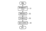
次に、動的輪郭抽出部22は、スネーク手法を用いて動的な輪郭抽出を行い、人物である可能性が高い部分の輪郭を抽出して(ステップS1)出力する。スネーク手法は、スネーク(snakes)と呼ばれる動的な閉曲線による輪郭線モデルを用いることが特徴で、画像中で物体の形状が時間的に変化していても対象物体の形状の抽出が可能であるという特徴を有している。このスネークは、対象物体の形状とスネークの形状が一致したときにエネルギーが最小になるように、その位置と形状によりエネルギー関数を設定する。具体的には曲線の滑らかさによる内部的なエネルギー、曲線と対象物体の輪郭との誤差のエネルギー、外的な拘束力によるエネルギーなどの和によって定義される。画像中の対象物体の輪郭に対して、エネルギーが局所最小解に到達するまで、位置と形状を動的に調整していくことによって、輪郭形状の抽出問題がエネルギー最小化という最適化問題として扱うことが可能となる。これによって、画像中における人物である可能性が高い領域を得ることができる。
【0017】
次に、頭位置抽出部23は、動的輪郭抽出部22の出力に基づいて、頭位置を抽出する(ステップS2)。ここで、頭位置を抽出する動作を図3、図9(a)を参照して説明する。図9(a)において、符号Aは、動的輪郭抽出部22の出力である動的輪郭である。まず、この動的輪郭で囲まれる領域の重心位置(1)を求め(ステップS6)、続いて、輪郭内の平均距離を距離画像を参照して求める(ステップS7)。次に、頭位置探索領域を設定する(ステップS8)。これは、輪郭重心のx座標に予め決められた人間の平均肩幅Wの1/2を加算と減算して得られるx座標値を求め、この2つのx座標値を通る垂直線(符号イ、ロ)を求める(2)。そして、2つの垂直線に挟まれた領域を探索領域とする。次に、この探索領域内の最上端を頭位置(3)とする(ステップS9)。この頭位置座標は指示方向算出部27と顔位置抽出部24へ通知される。
【0018】
次に、手位置抽出部25は、動的輪郭抽出で抽出された輪郭内における手の位置を抽出する(ステップS3)。ここで、図4を参照して、手位置抽出動作を説明する。手位置抽出部25は、頭位置座標と左右の手の届く範囲に基づいて手の探索領域を設定する(ステップS10)。続いて、手位置抽出部25は、先に設定した手の探索領域内に存在する動的輪郭抽出で抽出された輪郭内の平均距離を求める(ステップS11)。そして、手位置抽出部25は、ここで求めた平均距離が動的輪郭全体の平均距離±α内に収まっていれば、この輪郭を手と見なす判定をする(ステップS12)。ここで、αは腕の長さに相当する値に設定する。ここで、抽出された手位置の座標は、手先位置抽出部26へ通知される。
【0019】
次に、指示方向算出部27は、頭位置抽出部23、顔位置抽出部24及び手先位置抽出部26のそれぞれから通知された頭位置及び顔位置、手先位置に基づいて指示方向の判定を行う(ステップS4)。
【0020】
ここで、図10〜13を参照して、ステップS4において頭位置抽出部23、顔位置抽出部24及び手先位置抽出部26のそれぞれから通知された頭位置及び顔位置、手先位置に基づいて指示方向の判定を行うことにより、人物が指差している位置を検出する動作を説明する。図10は、指示方向算出部27の動作を示すフローチャートである。図11〜13は、指示方向算出動作を示す説明図である。
まず、顔位置抽出部24は、頭位置抽出部23より指示を出す人物の頭位置情報を取得する。また、手先位置抽出部26は、指示を出す人物の手位置情報を取得する(ステップS51)。ここで得られる情報は、頭位置の座標値、顔の中心部座標値と顔部分の肌色領域面積と髪部分の黒色領域面積、手位置の座標値である。
【0021】
次に、手先位置抽出部26は、取得した手位置の座標値Parm(図11(a))を中心点とする探索円を設定する。この探索円の直径は、腕より小さく、拳(掌)より大きくなるように設定する。例えば、半径12cmと予め決めておき、手位置の座標値Parmに基づき、カメラ1との距離を考慮して、画像上における探索円の大きさを決定して2次元画像上に設定する(図11(b))。続いて、手先位置抽出部26は、探索円内に存在する手の画素を抽出する。この抽出処理によって、各画素の3次元空間上の座標値が得られることとなる。そして、指示方向算出部27は、得られた複数の3次元座標値を用いて主成分分析の固有値解析法により手の主軸に相当する直線(図11(c)に示す符号L)を求める(ステップS52)。この直線は、3次元空間上の直線となる。
【0022】
次に、手先位置抽出部26は、求めた主軸と探索円内に存在する手を構成する画素の座標値より、探索円内存在する手の両端(図11(d)に示す符号E1、E2)を求める(ステップS53)。
【0023】
次に、先に求めた探索円内存在する手の両端のうち、どちらが手の先端であるかを判定し、手先位置Phandと手の方向ベクトルVarm(図11(e))を求める(ステップS54)。手の先端であるか否かの判定は、求めた両端に半径20cm探索円を設定し、2つの探索円内に手の部分に相当する画素が存在するか否かで判定する。図11(e)の例では、探索円C1内には、図11(b)の探索円で抽出した手の部分のみが存在するのに対して、探索円C2内には、図11(b)の探索円で抽出した手の部分以外の腕の部分が含まれているため、探索円C1側の端点E1が手先であることを判定することができる。
【0024】
これまでの動作によって、指示を出す人物の手先位置と手の方向ベクトルが求められたこととなり、ここで得られた結果は、指示方向算出部27へ出力する。
【0025】
次に、顔位置抽出部24は、顔部分の肌色領域面積と髪部分の黒色領域面積との比によって顔の向きを求め、さらに、目の位置を求める(ステップS55)。目の位置は、以下のようにして求める。まず、顔の中心部座標値Pheadのx成分の座標値(カメラ1からの距離方向)のみに8cmを加算し、得られた座標値P'headを中心として球面を定義し、仮想の頭とする。そして、球面の中心座標P'headと先に求めた手先位置座標Phandとを結ぶ線分と仮想の頭である球面との交点Cのx座標値の垂直面を定義し、交点Cのz座標を垂直に球面の中心から+15°回転した位置を目の位置Peyeとする(図12)。この目の位置Peyeは、指示方向算出部27へ出力する。
【0026】
次に、指示方向算出部27は、目の位置Peyeと手先位置Phandとを結ぶベクトルVey_haを求める(ステップS56)。続いて、指示方向算出部27は、(1)式によって、目の位置Peyeと手先位置Phandとを結ぶベクトルVey_haと、手の方向ベクトルVarmとを正規化して、合成ベクトルVpoを求める(ステップS57)。
【数1】

次に、指示方向算出部27は、直前の6フレーム以上の画像から取得したVarmとParmとから、平均ベクトルを求め、この平均ベクトルとの角度差が最小と最大であるものを取り除いたもののみから再び平均ベクトルを求め、この平均ベクトルとの角度差が所定値以内であるものが4フレーム以上得られたか否かを判定し(ステップS58)、この条件を満たすまで処理を繰り返す。
【0028】
次に、指示方向算出部27は、合成ベクトルVpoを延長して、物体との交点を求める(ステップS59)。この交点が、指示を出す人物が指差している位置に相当する。このとき、物体を床面とすると、指示を出した人物の足元に基づいて床面高さを求めるか、カメラ1の位置、パン角及びチルト角に基づいて床面の高さを求めるようにすれば、合成ベクトルVpoと床面の交点Fは算術演算で求めることが可能である(図13)。
【0029】
<第2の指示位置検出動作>
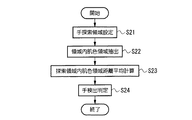
次に、図5を参照して、第2の指示位置検出動作を説明する。図5は、図2に示す手位置抽出(ステップS3)の動作を示す図であり、図4に示す第1の指示位置検出動作における手位置抽出動作に相当するものである。
まず、手位置抽出部25は、頭位置座標と左右の手の届く範囲に基づいて手の探索領域を設定する(ステップS21)。続いて、手位置抽出部25は、前処理で得られた肌色領域と動的領域に基づいて、動的領域内の肌色領域を抽出する(ステップS22)。次に、手位置抽出部25は、距離画像を参照して、ここで得られた肌色領域の平均距離を求める(ステップS23)。そして、手位置抽出部25は、ここで求めた平均距離が動的輪郭全体の平均距離±α内に収まっていれば、この輪郭を手と見なす判定をする(ステップS24)。ここで、αは腕の長さである。ここで、抽出された手位置の座標は指示方向算出部27へ通知される。
第2の指示位置検出動作において、図5に示す手位置抽出動作以外は、第1の指示位置検出動作と同一である。
【0030】
<第3の指示位置検出動作>
次に、図6、7、8を参照して第3の指示位置検出動作を説明する。まず、前処理部21は、カメラ1で得られる2枚の画像から距離画像を生成して、内部に保持する。続いて、前処理部21は、2台のカメラ1のうち基準カメラとして予め決められている一方のカメラの基準画像からエッジ抽出と肌色領域抽出を行い、抽出結果を内部に保持する。次に、動的輪郭抽出部22は、スネーク手法を用いて動的な輪郭抽出を行い、人物である可能性が高い部分の輪郭を抽出して(ステップS31)出力する。
【0031】
次に、頭位置抽出部23は、動的輪郭抽出部22の出力に基づいて、頭位置を抽出する(ステップS32)。ここでの動作は、第1の動作と同一であるので、詳細な説明を省略する。ここで抽出された頭位置座標は顔位置抽出部24、指示方向算出部27、手位置抽出部25へそれぞれ通知される。
【0032】
次に、顔位置抽出部24は、人物の顔の中心点を抽出する(ステップS33)。ここで、図7、9を参照して、顔の中心点を抽出する動作を説明する。まず、顔位置抽出部24は、顔探索領域を設定する(ステップS38)。この顔探索領域は、先に求めた頭位置の座標を参照して、頭位置を上端として予め決められている標準顔の大きさに基づく空間領域を論理的に定義することにより設定する。続いて、顔位置抽出部24は、先に設定した顔探索領域内の肌色領域を抽出し、この肌色領域の中心を顔位置として抽出する(ステップS39)。これによって図9(b)に示す顔位置(4)が抽出されたこととなる。
【0033】
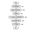
次に、手位置抽出部25、手先位置抽出部26は、手位置と手先(手首より先の部分)を抽出する(ステップS35)。ここで、図8を参照して、手位置抽出動作および手先抽出動作を説明する。手位置抽出部25は、頭位置座標と左右の手の届く範囲に基づいて手の探索領域を設定する(ステップS41)。続いて、手位置抽出部25は、前処理で得られた肌色領域と動的領域に基づいて、動的領域内の肌色領域を抽出する(ステップS42)。次に、手位置抽出部25は、距離画像を参照して、ここで得られた肌色領域の平均距離を求める。そして、手位置抽出部25は、ここで求めた平均距離が動的輪郭全体の平均距離±α内に収まっていれば、この輪郭を手と見なす判定をする(ステップS43)。ここで、αは腕の長さである。
【0034】
次に、手先位置抽出部26は、ステップS43において手と見なす輪郭の中心を基準として手先位置抽出用探索範囲を設定する(ステップS44)。この探索範囲は、距離画像を参照して、人物の腕の長さを推定して設定する。続いて手先位置抽出部26は、手先位置抽出用探索範囲内における肌色領域の輪郭の上下左右の端点を抽出する(ステップS45)。そして、手位置抽出部25は、得られた端点のうち顔の中心から最も遠い端点を手先位置として抽出する(ステップS46)。この手先位置座標は、指示方向算出部27へ通知される。
【0035】
次に、指示方向算出部27は、通知された頭位置、顔位置及び手先位置座標に基づいて指示方向を判定する(ステップS35)。この指示方向判定処理動作は前述した動作と同一であるので、ここでは詳細な説明を省略する。
【0036】
このように、指示位置検出を行う対象となる人物の抽出に動的輪郭抽出を適用するとともに、同時に距離画像を参照するようにしたため、複数の人物が視野内に存在する場合であっても指示位置検出を確実に行うことが可能となるとともに、抽出された輪郭情報から顔や手などの人物の特徴点を検出し、これらの特徴点の位置関係から人物が指差している位置を検出するようにしたため、信頼性が高くかつ高速処理が可能である指示位置検出を実現することができる。また、床面等の位置を正確に指示することができるため、自律ロボットに対して移動先を指示したり、床に落ちたものを拾うように指示したりすることが容易になる。
【0037】
なお、図1における各処理部の機能を実現するためのプログラムをコンピュータ読み取り可能な記録媒体に記録して、この記録媒体に記録されたプログラムをコンピュータシステムに読み込ませ、実行することにより指示位置検出処理及び応答処理を行ってもよい。なお、ここでいう「コンピュータシステム」とは、OSや周辺機器等のハードウェアを含むものとする。また、「コンピュータシステム」は、WWWシステムを利用している場合であれば、ホームページ提供環境(あるいは表示環境)も含むものとする。また、「コンピュータ読み取り可能な記録媒体」とは、フレキシブルディスク、光磁気ディスク、ROM、CD−ROM等の可搬媒体、コンピュータシステムに内蔵されるハードディスク等の記憶装置のことをいう。さらに「コンピュータ読み取り可能な記録媒体」とは、インターネット等のネットワークや電話回線等の通信回線を介してプログラムが送信された場合のサーバやクライアントとなるコンピュータシステム内部の揮発性メモリ(RAM)のように、一定時間プログラムを保持しているものも含むものとする。
【0038】
また、上記プログラムは、このプログラムを記憶装置等に格納したコンピュータシステムから、伝送媒体を介して、あるいは、伝送媒体中の伝送波により他のコンピュータシステムに伝送されてもよい。ここで、プログラムを伝送する「伝送媒体」は、インターネット等のネットワーク(通信網)や電話回線等の通信回線(通信線)のように情報を伝送する機能を有する媒体のことをいう。また、上記プログラムは、前述した機能の一部を実現するためのものであっても良い。さらに、前述した機能をコンピュータシステムにすでに記録されているプログラムとの組み合わせで実現できるもの、いわゆる差分ファイル(差分プログラム)であっても良い。
【0039】
【発明の効果】
以上説明したように、請求項1に記載の発明によれば、距離情報を含む手の位置から手の向きと手先位置を検出するともに、距離情報を含む人物の頭の位置を検出し、検出された頭部位置と手先の位置と手の向きに基づいて、人物が指示する方向を検出するようにし、この方向から指示する位置を検出するようにしたため、人物の意図する指示位置を高精度に検出することができるという効果が得られる。また、手の向きに基づいて指示位置を検出するようにしたため、腕を曲げても精度良く指示位置の検出が可能になるという効果が得られる。さらに、距離情報を含む位置に基づいて指示位置を検出するようにしたため、検出時のカメラの設置位置や背景の制限を無くすことができるという効果が得られる。
また、請求項2に記載の発明によれば、目の位置と手先の位置と手の向きに基づいて人物が指示する方向を検出するようにしたため、人物が指示する位置をさらに高精度に検出することができるという効果が得られる。
また、請求項3に記載の発明によれば、手の位置に基づいて画像中に所定の探索領域を設定するようにしたため、手先の位置及び手の向きを検出する速度を向上することができるという効果が得られる。
また、請求項4に記載の発明によれば、探索領域内に存在する手を構成する画素データの分布に基づいて手の向きを検出するようにしたため、複雑な処理を用いることなく演算のみによって手の向きを検出することができるという効果が得られる。
また、請求項5に記載の発明によれば、検出された人物が指示する方向と画像中に存在する所定の物体との交点を算出し、指示する位置を検出するようにしたため、床や壁などを指差した場合においても簡単な演算で位置の検出をすることができるという効果が得られる。
また、請求項6に記載の発明によれば、指示位置を高精度に検出することができる指示位置検出装置を自律ロボットに備えたため、高度なヒューマン・ロボットインタフェースを実現することができるという効果が得られる。
【図面の簡単な説明】
【図1】 本発明の一実施形態の構成を示すブロック図である。
【図2】 図1に示す指示位置検出部2の動作を示すフローチャートである。
【図3】 図1に示す指示位置検出部2の動作を示すフローチャートである。
【図4】 図1に示す指示位置検出部2の動作を示すフローチャートである。
【図5】 図1に示す指示位置検出部2の動作を示すフローチャートである。
【図6】 図1に示す指示位置検出部2の動作を示すフローチャートである。
【図7】 図1に示す指示位置検出部2の動作を示すフローチャートである。
【図8】 図1に示す指示位置検出部2の動作を示すフローチャートである。
【図9】 図1に示す指示位置検出部2の動作を示す説明図である。
【図10】 指示方向を算出する動作を示すフローチャートである。
【図11】 手先位置を算出する動作を示す説明図である。
【図12】 指差している方向を算出する動作を示す説明図である。
【図13】 指差している方向を算出する動作を示す説明図である。
【図14】 自律ロボットの外観を示す説明図である。
【符号の説明】
1・・・カメラ 2・・・指示位置検出部
21・・・前処理部 22・・・動的輪郭抽出部
23・・・頭位置抽出部 24・・・顔位置抽出部
25・・・手位置抽出部 26・・・手先位置抽出部
27・・・指示方向算出部 5・・・応答処理部
6・・・行動制御部[0001]
BACKGROUND OF THE INVENTION
The present invention relates to an indication position detection device and an autonomous robot that detect an indication position that a human gives by recognizing a human posture using an image.
[0002]
[Prior art]
2. Description of the Related Art Conventionally, an autonomous robot that recognizes an instruction to itself and performs an action by recognizing a voice instruction issued by a human is known. This is characterized in that when an instruction is given to an autonomous robot, the person who gives the instruction can give an instruction without using a special device.
By the way, the voice instruction system has a problem that the voice recognition rate is lowered in a place where there is a lot of noise, so that the instruction cannot be accurately transmitted. Furthermore, in speech recognition, in order to improve the recognition rate, it is necessary to register in advance the speech of a person who emits speech, and not everyone can give an instruction.
[0003]
In order to solve such a problem, a method of recognizing a person's body posture using image information and recognizing an instruction meaning the posture has been attempted. For example, it is described in IEEJ Transactions C, Electronics, Information and Systems Division Vol.121-C (2001.9) p1388-p1394 “Direction Estimation of Omnidirectional Pointing Gestures Using Multi-Camera” (hereinafter referred to as Prior Art 1) A method for estimating the direction of a pointing gesture is known. In this method, first, a face area is extracted from images obtained by photographing a person with a plurality of cameras, a front face is detected based on a face orientation estimation result, and an eye position is specified. Next, hand region extraction is performed from the obtained image, and the end of this hand region is specified as the fingertip position. Then, the spatial positions of the eye and fingertip obtained here are obtained, and the extension line connecting these two points is estimated as the pointing direction. Also, described in IEICE Transactions C, Electronic, Information and Systems Division Vol.121-C (2001.9) p1464-p1470 “Interactive Hand Pointer Projecting Marks in Real Space” (hereinafter referred to as Prior Art 2) An interactive hand pointer method is known. In this method, a fingertip position obtained by block matching between an image obtained by photographing a hand of a person who gives an instruction under a simple background with a camera and a template image of a fingertip prepared in advance, and a certain region from this position The straight line connecting the center position of the base of the finger inside is the pointing direction.
According to these methods, the robot can be used as a human-robot interface for recognizing an object in a direction pointed by the fingertip of a person who issues an instruction and causing the robot to perform the following operation.
[0004]
[Problems to be solved by the invention]
However, as in the
Further, as in Prior
[0005]
The present invention has been made in view of such circumstances, and a pointing position detection device and a pointing position detection result capable of performing a pointing operation in a natural state and capable of performing highly accurate pointing position detection. The purpose is to provide an autonomous robot that takes action based on.
[0006]
[Means for Solving the Problems]
The invention according to
According to this configuration, the hand position is determined from the position of the hand including the distance information. direction And the position of the hand and the position of the head of the person including the distance information are detected. direction Therefore, the direction indicated by the person is detected, and the position indicated from this direction is detected, so that the indicated position can be detected with high accuracy. Also hand direction Therefore, the indicated position can be detected with high accuracy even if the arm is bent. Furthermore, since the designated position is detected based on the position including the distance information, it is possible to eliminate restrictions on the camera installation position and background at the time of detection.
[0007]
The invention according to
According to this configuration, the position of the eyes, the position of the hand and the hand direction Since the direction indicated by the person is detected based on the above, the position indicated by the person can be detected with higher accuracy.
[0008]
The invention according to
According to this configuration, since the predetermined search area is set in the image based on the position of the hand, the position of the hand and the hand direction Can be detected at a higher speed.
[0009]
According to a fourth aspect of the present invention, there is provided a hand based on a distribution of pixel data constituting the hand existing in the search area. direction It is characterized by detecting.
According to this configuration, the hand is based on the distribution of pixel data constituting the hand existing in the search area. direction Because it detects the direction Can be detected.
[0010]
The invention according to
According to this configuration, since the intersection point between the direction indicated by the detected person and a predetermined object existing in the image is calculated and the indicated position is detected, even when the floor or wall is pointed to The position can be detected with a simple calculation.
[0011]
According to a sixth aspect of the present invention, an autonomous robot includes the pointing position detection device according to any one of the first to fifth aspects.
According to this configuration, since the autonomous robot is equipped with the designated position detection device that can detect the designated position with high accuracy, an advanced human-robot interface can be realized.
[0012]
DETAILED DESCRIPTION OF THE INVENTION
Hereinafter, a pointing position detection apparatus and an autonomous robot according to an embodiment of the present invention will be described with reference to the drawings. FIG. 1 is a block diagram showing the configuration of the embodiment.
[0013]
Reference numeral 21 denotes a preprocessing unit that performs preprocessing for simplifying subsequent processing on an image obtained by the
[0014]
Here, the configuration of the autonomous robot R will be briefly described. FIG. 14 is an explanatory diagram showing an external appearance of a biped humanoid autonomous robot R. In this figure, reference symbol R1 is a control device mounting unit on which the indicated
[0015]
<First indicated position detection operation>
Next, the operation of the designated
[0016]
Next, the dynamic
[0017]
Next, the head
[0018]
Next, the hand
[0019]
Next, the instruction
[0020]
Here, referring to FIGS. 10 to 13, an instruction is given based on the head position, the face position, and the hand position notified from each of the head
First, the face
[0021]
Next, the hand
[0022]
Next, the hand
[0023]
Next, it is determined which of the two ends of the hand existing in the previously obtained search circle is the tip of the hand, and the hand position Phand and the hand direction vector Varm (FIG. 11E) are obtained (step S54). ). Whether or not it is the tip of the hand is determined by setting a search circle with a radius of 20 cm at the obtained both ends and determining whether or not a pixel corresponding to the hand portion exists in the two search circles. In the example of FIG. 11 (e), only the hand portion extracted in the search circle of FIG. 11 (b) exists in the search circle C1, whereas in the search circle C2, FIG. 11 (b) ) Includes an arm portion other than the hand portion extracted by the search circle, and therefore, it can be determined that the end point E1 on the search circle C1 side is the tip.
[0024]
Through the operations so far, the hand position and hand direction vector of the person giving the instruction are obtained, and the result obtained here is output to the instruction
[0025]
Next, the face
[0026]
Next, the instruction
[Expression 1]
Next, the indication
[0028]
Next, the instruction
[0029]
<Second designated position detection operation>
Next, the second designated position detection operation will be described with reference to FIG. FIG. 5 is a diagram showing the operation of the hand position extraction (step S3) shown in FIG. 2, and corresponds to the hand position extraction operation in the first designated position detection operation shown in FIG.
First, the hand
The second designated position detecting operation is the same as the first designated position detecting operation except for the hand position extracting operation shown in FIG.
[0030]
<Third designated position detection operation>
Next, the third designated position detection operation will be described with reference to FIGS. First, the pre-processing unit 21 generates a distance image from two images obtained by the
[0031]
Next, the head
[0032]
Next, the face
[0033]
Next, the hand
[0034]
Next, the hand
[0035]
Next, the instruction
[0036]
As described above, since the dynamic contour extraction is applied to the extraction of the person who is the target position detection target, and the distance image is referred to at the same time, the instruction is given even when a plurality of persons exist in the field of view. Position detection can be performed reliably, and feature points of a person such as a face and hand are detected from the extracted contour information, and the position where the person is pointing is detected from the positional relationship of these feature points. As a result, it is possible to realize pointing position detection that is highly reliable and capable of high-speed processing. Further, since the position of the floor surface or the like can be accurately instructed, it becomes easy to instruct the autonomous robot to move to or to pick up what has fallen on the floor.
[0037]
1 is recorded on a computer-readable recording medium, and the program recorded on the recording medium is read into the computer system and executed to detect the indicated position. Processing and response processing may be performed. Here, the “computer system” includes an OS and hardware such as peripheral devices. Further, the “computer system” includes a homepage providing environment (or display environment) if a WWW system is used. The “computer-readable recording medium” refers to a storage device such as a flexible medium, a magneto-optical disk, a portable medium such as a ROM and a CD-ROM, and a hard disk incorporated in a computer system. Further, the “computer-readable recording medium” refers to a volatile memory (RAM) in a computer system that becomes a server or a client when a program is transmitted via a network such as the Internet or a communication line such as a telephone line. In addition, those holding programs for a certain period of time are also included.
[0038]
The program may be transmitted from a computer system storing the program in a storage device or the like to another computer system via a transmission medium or by a transmission wave in the transmission medium. Here, the “transmission medium” for transmitting the program refers to a medium having a function of transmitting information, such as a network (communication network) such as the Internet or a communication line (communication line) such as a telephone line. The program may be for realizing a part of the functions described above. Furthermore, what can implement | achieve the function mentioned above in combination with the program already recorded on the computer system, and what is called a difference file (difference program) may be sufficient.
[0039]
【The invention's effect】
As described above, according to the first aspect of the present invention, the hand position is determined from the hand position including the distance information. direction And the position of the hand and the position of the head of the person including the distance information are detected. direction Based on this, the direction indicated by the person is detected, and the position indicated from this direction is detected. Highly accurate pointing position intended by a person The effect that it can detect is acquired. Also hand direction Since the designated position is detected based on the above, it is possible to obtain the effect that the designated position can be accurately detected even if the arm is bent. Furthermore, since the designated position is detected based on the position including the distance information, it is possible to eliminate the restriction of the camera installation position and background at the time of detection.
According to the invention of
According to the third aspect of the present invention, since the predetermined search area is set in the image based on the position of the hand, the position of the hand and the hand direction The effect that the speed which detects can be improved is acquired.
According to the invention described in
According to the fifth aspect of the present invention, the intersection point between the direction indicated by the detected person and the predetermined object existing in the image is calculated, and the indicated position is detected. Even if the user points to the position, the effect of being able to detect the position with a simple calculation is obtained.
In addition, according to the invention described in
[Brief description of the drawings]
FIG. 1 is a block diagram showing a configuration of an embodiment of the present invention.
FIG. 2 is a flowchart showing an operation of a designated
FIG. 3 is a flowchart showing an operation of a designated
4 is a flowchart showing the operation of a designated
FIG. 5 is a flowchart showing an operation of a designated
6 is a flowchart showing an operation of a designated
7 is a flowchart showing the operation of the indicated
FIG. 8 is a flowchart showing an operation of a designated
FIG. 9 is an explanatory diagram showing an operation of the designated
FIG. 10 is a flowchart showing an operation for calculating an instruction direction.
FIG. 11 is an explanatory diagram illustrating an operation for calculating a hand position.
FIG. 12 is an explanatory diagram illustrating an operation of calculating a pointing direction.
FIG. 13 is an explanatory diagram illustrating an operation of calculating a pointing direction.
FIG. 14 is an explanatory diagram showing the appearance of an autonomous robot.
[Explanation of symbols]
DESCRIPTION OF
21 ...
23 ... Head
25: Hand position extraction unit 26: Hand position extraction unit
27: Instruction
6 ... Action control unit
Claims (6)
前記画像に基づいて少なくとも距離情報を含む前記人物の頭部位置を検出する手段と、
前記画像に基づいて少なくとも距離情報を含む前記人物の手の位置を検出する手段と、
前記検出された手の位置に基づいて手先の位置および手の向きを算出する手段と、
前記検出された頭部位置と前記検出された手先の位置及び手の向きに基づいて、人物が指示する方向を検出する手段を備え、
前記検出された人物が指示する方向に基づいて指示する位置を検出するようにしたことを特徴とする指示位置検出装置。In an indicated position detection device for detecting a person from images taken by a plurality of cameras and detecting a position indicated by the person,
Means for detecting a head position of the person including at least distance information based on the image;
Means for detecting a position of the person's hand containing at least distance information based on the image;
Means for calculating a hand position and a hand orientation based on the detected hand position;
Means for detecting a direction indicated by a person based on the detected head position and the detected position and orientation of the hand;
An indicated position detection apparatus that detects an indicated position based on a direction indicated by the detected person.
Priority Applications (2)
| Application Number | Priority Date | Filing Date | Title |
|---|---|---|---|
| JP2002231899A JP4149213B2 (en) | 2002-07-12 | 2002-08-08 | Pointed position detection device and autonomous robot |
| US10/616,288 US7460687B2 (en) | 2002-07-12 | 2003-07-10 | Watermarking scheme for digital video |
Applications Claiming Priority (2)
| Application Number | Priority Date | Filing Date | Title |
|---|---|---|---|
| JP2002204048 | 2002-07-12 | ||
| JP2002231899A JP4149213B2 (en) | 2002-07-12 | 2002-08-08 | Pointed position detection device and autonomous robot |
Publications (3)
| Publication Number | Publication Date |
|---|---|
| JP2004094288A JP2004094288A (en) | 2004-03-25 |
| JP2004094288A5 JP2004094288A5 (en) | 2005-06-30 |
| JP4149213B2 true JP4149213B2 (en) | 2008-09-10 |
Family
ID=32072236
Family Applications (1)
| Application Number | Title | Priority Date | Filing Date |
|---|---|---|---|
| JP2002231899A Expired - Fee Related JP4149213B2 (en) | 2002-07-12 | 2002-08-08 | Pointed position detection device and autonomous robot |
Country Status (2)
| Country | Link |
|---|---|
| US (1) | US7460687B2 (en) |
| JP (1) | JP4149213B2 (en) |
Cited By (1)
| Publication number | Priority date | Publication date | Assignee | Title |
|---|---|---|---|---|
| US11195525B2 (en) | 2018-06-13 | 2021-12-07 | Panasonic Intellectual Property Corporation Of America | Operation terminal, voice inputting method, and computer-readable recording medium |
Families Citing this family (33)
| Publication number | Priority date | Publication date | Assignee | Title |
|---|---|---|---|---|
| EP1586423B1 (en) | 2002-12-10 | 2011-10-05 | Honda Motor Co., Ltd. | Robot control device, robot control method, and robot control program |
| JP2005290813A (en) | 2004-03-31 | 2005-10-20 | Honda Motor Co Ltd | Parking guidance robot |
| JP2005301479A (en) * | 2004-04-08 | 2005-10-27 | Akinori Yoshino | Instruction input device based on projected action of presenter |
| US7308112B2 (en) * | 2004-05-14 | 2007-12-11 | Honda Motor Co., Ltd. | Sign based human-machine interaction |
| JP4459735B2 (en) | 2004-06-30 | 2010-04-28 | 本田技研工業株式会社 | Product explanation robot |
| JP4611675B2 (en) | 2004-06-30 | 2011-01-12 | 本田技研工業株式会社 | Customer service robot |
| JP2008505417A (en) * | 2004-07-05 | 2008-02-21 | コーニンクレッカ フィリップス エレクトロニクス エヌ ヴィ | Method for establishing user access to a system |
| KR100620452B1 (en) * | 2004-08-09 | 2006-09-08 | 삼성전자주식회사 | Method for processing image |
| JP4384021B2 (en) * | 2004-12-14 | 2009-12-16 | 本田技研工業株式会社 | Legged robot controller |
| JP4575829B2 (en) * | 2005-03-30 | 2010-11-04 | 財団法人エヌエイチケイエンジニアリングサービス | Display screen position analysis device and display screen position analysis program |
| US7664571B2 (en) * | 2005-04-18 | 2010-02-16 | Honda Motor Co., Ltd. | Controlling a robot using pose |
| EP1795314B1 (en) * | 2005-12-12 | 2009-10-21 | HONDA MOTOR CO., Ltd. | Legged mobile robot control system |
| US8125526B2 (en) * | 2006-02-03 | 2012-02-28 | Olympus Imaging Corp. | Camera for selecting an image from a plurality of images based on a face portion and contour of a subject in the image |
| JP4675822B2 (en) * | 2006-05-01 | 2011-04-27 | 本田技研工業株式会社 | Wireless communication area measurement system, method and program |
| WO2009128064A2 (en) * | 2008-04-14 | 2009-10-22 | Pointgrab Ltd. | Vision based pointing device emulation |
| US8253802B1 (en) * | 2009-09-01 | 2012-08-28 | Sandia Corporation | Technique for identifying, tracing, or tracking objects in image data |
| GB2483168B (en) | 2009-10-13 | 2013-06-12 | Pointgrab Ltd | Computer vision gesture based control of a device |
| KR20110055062A (en) * | 2009-11-19 | 2011-05-25 | 삼성전자주식회사 | Robot system and method for controlling the same |
| CN102122343A (en) * | 2010-01-07 | 2011-07-13 | 索尼公司 | Method and device for determining angle of inclination of body and estimating gesture |
| JP5287792B2 (en) * | 2010-05-10 | 2013-09-11 | ソニー株式会社 | Information processing apparatus, information processing method, and program |
| JP5648443B2 (en) * | 2010-11-26 | 2015-01-07 | ソニー株式会社 | Image processing apparatus and method, and program |
| JP5845002B2 (en) | 2011-06-07 | 2016-01-20 | ソニー株式会社 | Image processing apparatus and method, and program |
| KR101302638B1 (en) * | 2011-07-08 | 2013-09-05 | 더디엔에이 주식회사 | Method, terminal, and computer readable recording medium for controlling content by detecting gesture of head and gesture of hand |
| DE112011105917T5 (en) * | 2011-12-27 | 2014-09-18 | Hewlett Packard Development Company, L.P. | User interface device |
| US8938124B2 (en) | 2012-05-10 | 2015-01-20 | Pointgrab Ltd. | Computer vision based tracking of a hand |
| EP2680228B1 (en) | 2012-06-25 | 2014-11-26 | Softkinetic Software | Improvements in or relating to three dimensional close interactions. |
| JP6108437B2 (en) * | 2012-11-28 | 2017-04-05 | Necソリューションイノベータ株式会社 | Finger direction identification system, finger direction identification method, and program thereof |
| US10126820B1 (en) * | 2012-11-29 | 2018-11-13 | Amazon Technologies, Inc. | Open and closed hand detection |
| CN106464793B (en) * | 2013-11-18 | 2019-08-02 | 奥林巴斯株式会社 | Photographic device and camera shooting householder method |
| JP6430340B2 (en) | 2015-07-31 | 2018-11-28 | 株式会社東芝 | Position input device and position input method |
| FI20155599A (en) * | 2015-08-21 | 2017-02-22 | Konecranes Global Oy | Control of a lifting device |
| KR102429764B1 (en) | 2018-02-01 | 2022-08-08 | 삼성전자주식회사 | An electronic device recognizing a gesture of a user |
| CN114971948A (en) * | 2021-02-20 | 2022-08-30 | 广东博智林机器人有限公司 | Position adjusting method, device, equipment and medium |
Family Cites Families (5)
| Publication number | Priority date | Publication date | Assignee | Title |
|---|---|---|---|---|
| US5499306A (en) * | 1993-03-08 | 1996-03-12 | Nippondenso Co., Ltd. | Position-and-attitude recognition method and apparatus by use of image pickup means |
| JP3749369B2 (en) * | 1997-03-21 | 2006-02-22 | 株式会社竹中工務店 | Hand pointing device |
| DE19736995B4 (en) * | 1997-08-26 | 2009-05-07 | Fraunhofer-Gesellschaft zur Förderung der angewandten Forschung e.V. | Device for determining a fixation point |
| JP4332649B2 (en) | 1999-06-08 | 2009-09-16 | 独立行政法人情報通信研究機構 | Hand shape and posture recognition device, hand shape and posture recognition method, and recording medium storing a program for executing the method |
| SE0000850D0 (en) | 2000-03-13 | 2000-03-13 | Pink Solution Ab | Recognition arrangement |
-
2002
- 2002-08-08 JP JP2002231899A patent/JP4149213B2/en not_active Expired - Fee Related
-
2003
- 2003-07-10 US US10/616,288 patent/US7460687B2/en not_active Expired - Fee Related
Cited By (1)
| Publication number | Priority date | Publication date | Assignee | Title |
|---|---|---|---|---|
| US11195525B2 (en) | 2018-06-13 | 2021-12-07 | Panasonic Intellectual Property Corporation Of America | Operation terminal, voice inputting method, and computer-readable recording medium |
Also Published As
| Publication number | Publication date |
|---|---|
| JP2004094288A (en) | 2004-03-25 |
| US20040101192A1 (en) | 2004-05-27 |
| US7460687B2 (en) | 2008-12-02 |
Similar Documents
| Publication | Publication Date | Title |
|---|---|---|
| JP4149213B2 (en) | Pointed position detection device and autonomous robot | |
| US7340100B2 (en) | Posture recognition apparatus and autonomous robot | |
| EP3781896B1 (en) | System for locating and identifying an object in unconstrained environments | |
| CN110570455B (en) | Whole body three-dimensional posture tracking method for room VR | |
| Ye et al. | Accurate 3d pose estimation from a single depth image | |
| Dorfmuller-Ulhaas et al. | Finger tracking for interaction in augmented environments | |
| US9898651B2 (en) | Upper-body skeleton extraction from depth maps | |
| US9159134B2 (en) | Method and apparatus for estimating a pose | |
| US8428306B2 (en) | Information processor and information processing method for performing process adapted to user motion | |
| JP4435212B2 (en) | Posture recognition device and autonomous robot | |
| Triesch et al. | Robotic gesture recognition | |
| JP2004504684A (en) | Face image processing system | |
| WO2022042304A1 (en) | Method and apparatus for identifying scene contour, and computer-readable medium and electronic device | |
| JP2018119833A (en) | Information processing device, system, estimation method, computer program, and storage medium | |
| JPH06138137A (en) | Moving-object extraction apparatus | |
| JP3416666B2 (en) | Head posture measurement device and CG character control device | |
| JPH08212327A (en) | Gesture recognition device | |
| Azhar et al. | Significant body point labeling and tracking | |
| JP6810442B2 (en) | A camera assembly, a finger shape detection system using the camera assembly, a finger shape detection method using the camera assembly, a program for implementing the detection method, and a storage medium for the program. | |
| Che et al. | Real-time 3d hand gesture based mobile interaction interface | |
| Li et al. | Fingertip data fusion of Kinect v2 and leap motion in unity. | |
| US20220415094A1 (en) | Method and system for estimating gesture of user from two-dimensional image, and non-transitory computer-readable recording medium | |
| de La Rivière et al. | Hand Postures Recognition in Large–Display VR Environments | |
| Chu et al. | Real-time 3d body pose tracking from multiple 2d images | |
| Akhavizadegan et al. | REAL-TIME AUTOMATED CONTOUR BASED MOTION TRACKING USING A SINGLE-CAMERA FOR UPPER LIMB ANGULAR MOTION MEASUREMENT |
Legal Events
| Date | Code | Title | Description |
|---|---|---|---|
| A521 | Written amendment |
Free format text: JAPANESE INTERMEDIATE CODE: A523 Effective date: 20041013 |
|
| A621 | Written request for application examination |
Free format text: JAPANESE INTERMEDIATE CODE: A621 Effective date: 20041013 |
|
| A131 | Notification of reasons for refusal |
Free format text: JAPANESE INTERMEDIATE CODE: A131 Effective date: 20071211 |
|
| A131 | Notification of reasons for refusal |
Free format text: JAPANESE INTERMEDIATE CODE: A131 Effective date: 20080318 |
|
| TRDD | Decision of grant or rejection written | ||
| A01 | Written decision to grant a patent or to grant a registration (utility model) |
Free format text: JAPANESE INTERMEDIATE CODE: A01 Effective date: 20080617 |
|
| A01 | Written decision to grant a patent or to grant a registration (utility model) |
Free format text: JAPANESE INTERMEDIATE CODE: A01 |
|
| A61 | First payment of annual fees (during grant procedure) |
Free format text: JAPANESE INTERMEDIATE CODE: A61 Effective date: 20080625 |
|
| FPAY | Renewal fee payment (event date is renewal date of database) |
Free format text: PAYMENT UNTIL: 20110704 Year of fee payment: 3 |
|
| R150 | Certificate of patent or registration of utility model |
Ref document number: 4149213 Country of ref document: JP Free format text: JAPANESE INTERMEDIATE CODE: R150 Free format text: JAPANESE INTERMEDIATE CODE: R150 |
|
| FPAY | Renewal fee payment (event date is renewal date of database) |
Free format text: PAYMENT UNTIL: 20110704 Year of fee payment: 3 |
|
| FPAY | Renewal fee payment (event date is renewal date of database) |
Free format text: PAYMENT UNTIL: 20120704 Year of fee payment: 4 |
|
| FPAY | Renewal fee payment (event date is renewal date of database) |
Free format text: PAYMENT UNTIL: 20120704 Year of fee payment: 4 |
|
| FPAY | Renewal fee payment (event date is renewal date of database) |
Free format text: PAYMENT UNTIL: 20130704 Year of fee payment: 5 |
|
| FPAY | Renewal fee payment (event date is renewal date of database) |
Free format text: PAYMENT UNTIL: 20140704 Year of fee payment: 6 |
|
| R250 | Receipt of annual fees |
Free format text: JAPANESE INTERMEDIATE CODE: R250 |
|
| LAPS | Cancellation because of no payment of annual fees |