JP4148778B2 - Microfluidic interface equipment with arrays - Google Patents
Microfluidic interface equipment with arrays Download PDFInfo
- Publication number
- JP4148778B2 JP4148778B2 JP2002571216A JP2002571216A JP4148778B2 JP 4148778 B2 JP4148778 B2 JP 4148778B2 JP 2002571216 A JP2002571216 A JP 2002571216A JP 2002571216 A JP2002571216 A JP 2002571216A JP 4148778 B2 JP4148778 B2 JP 4148778B2
- Authority
- JP
- Japan
- Prior art keywords
- interface
- interface device
- microarray
- fluid
- layer
- Prior art date
- Legal status (The legal status is an assumption and is not a legal conclusion. Google has not performed a legal analysis and makes no representation as to the accuracy of the status listed.)
- Expired - Fee Related
Links
Images


Classifications
-
- B—PERFORMING OPERATIONS; TRANSPORTING
- B01—PHYSICAL OR CHEMICAL PROCESSES OR APPARATUS IN GENERAL
- B01J—CHEMICAL OR PHYSICAL PROCESSES, e.g. CATALYSIS OR COLLOID CHEMISTRY; THEIR RELEVANT APPARATUS
- B01J19/00—Chemical, physical or physico-chemical processes in general; Their relevant apparatus
- B01J19/0093—Microreactors, e.g. miniaturised or microfabricated reactors
-
- G—PHYSICS
- G01—MEASURING; TESTING
- G01N—INVESTIGATING OR ANALYSING MATERIALS BY DETERMINING THEIR CHEMICAL OR PHYSICAL PROPERTIES
- G01N33/00—Investigating or analysing materials by specific methods not covered by groups G01N1/00 - G01N31/00
- G01N33/48—Biological material, e.g. blood, urine; Haemocytometers
- G01N33/50—Chemical analysis of biological material, e.g. blood, urine; Testing involving biospecific ligand binding methods; Immunological testing
- G01N33/68—Chemical analysis of biological material, e.g. blood, urine; Testing involving biospecific ligand binding methods; Immunological testing involving proteins, peptides or amino acids
-
- B—PERFORMING OPERATIONS; TRANSPORTING
- B01—PHYSICAL OR CHEMICAL PROCESSES OR APPARATUS IN GENERAL
- B01F—MIXING, e.g. DISSOLVING, EMULSIFYING OR DISPERSING
- B01F25/00—Flow mixers; Mixers for falling materials, e.g. solid particles
- B01F25/50—Circulation mixers, e.g. wherein at least part of the mixture is discharged from and reintroduced into a receptacle
-
- B—PERFORMING OPERATIONS; TRANSPORTING
- B01—PHYSICAL OR CHEMICAL PROCESSES OR APPARATUS IN GENERAL
- B01F—MIXING, e.g. DISSOLVING, EMULSIFYING OR DISPERSING
- B01F31/00—Mixers with shaking, oscillating, or vibrating mechanisms
- B01F31/30—Mixers with shaking, oscillating, or vibrating mechanisms comprising a receptacle to only a part of which the shaking, oscillating, or vibrating movement is imparted
- B01F31/31—Mixers with shaking, oscillating, or vibrating mechanisms comprising a receptacle to only a part of which the shaking, oscillating, or vibrating movement is imparted using receptacles with deformable parts, e.g. membranes, to which a motion is imparted
-
- B—PERFORMING OPERATIONS; TRANSPORTING
- B01—PHYSICAL OR CHEMICAL PROCESSES OR APPARATUS IN GENERAL
- B01F—MIXING, e.g. DISSOLVING, EMULSIFYING OR DISPERSING
- B01F31/00—Mixers with shaking, oscillating, or vibrating mechanisms
- B01F31/80—Mixing by means of high-frequency vibrations above one kHz, e.g. ultrasonic vibrations
- B01F31/86—Mixing by means of high-frequency vibrations above one kHz, e.g. ultrasonic vibrations with vibration of the receptacle or part of it
-
- B—PERFORMING OPERATIONS; TRANSPORTING
- B01—PHYSICAL OR CHEMICAL PROCESSES OR APPARATUS IN GENERAL
- B01L—CHEMICAL OR PHYSICAL LABORATORY APPARATUS FOR GENERAL USE
- B01L3/00—Containers or dishes for laboratory use, e.g. laboratory glassware; Droppers
- B01L3/02—Burettes; Pipettes
- B01L3/0289—Apparatus for withdrawing or distributing predetermined quantities of fluid
- B01L3/0293—Apparatus for withdrawing or distributing predetermined quantities of fluid for liquids
-
- B—PERFORMING OPERATIONS; TRANSPORTING
- B01—PHYSICAL OR CHEMICAL PROCESSES OR APPARATUS IN GENERAL
- B01L—CHEMICAL OR PHYSICAL LABORATORY APPARATUS FOR GENERAL USE
- B01L3/00—Containers or dishes for laboratory use, e.g. laboratory glassware; Droppers
- B01L3/50—Containers for the purpose of retaining a material to be analysed, e.g. test tubes
- B01L3/502—Containers for the purpose of retaining a material to be analysed, e.g. test tubes with fluid transport, e.g. in multi-compartment structures
- B01L3/5027—Containers for the purpose of retaining a material to be analysed, e.g. test tubes with fluid transport, e.g. in multi-compartment structures by integrated microfluidic structures, i.e. dimensions of channels and chambers are such that surface tension forces are important, e.g. lab-on-a-chip
- B01L3/502715—Containers for the purpose of retaining a material to be analysed, e.g. test tubes with fluid transport, e.g. in multi-compartment structures by integrated microfluidic structures, i.e. dimensions of channels and chambers are such that surface tension forces are important, e.g. lab-on-a-chip characterised by interfacing components, e.g. fluidic, electrical, optical or mechanical interfaces
-
- B—PERFORMING OPERATIONS; TRANSPORTING
- B01—PHYSICAL OR CHEMICAL PROCESSES OR APPARATUS IN GENERAL
- B01L—CHEMICAL OR PHYSICAL LABORATORY APPARATUS FOR GENERAL USE
- B01L3/00—Containers or dishes for laboratory use, e.g. laboratory glassware; Droppers
- B01L3/50—Containers for the purpose of retaining a material to be analysed, e.g. test tubes
- B01L3/502—Containers for the purpose of retaining a material to be analysed, e.g. test tubes with fluid transport, e.g. in multi-compartment structures
- B01L3/5027—Containers for the purpose of retaining a material to be analysed, e.g. test tubes with fluid transport, e.g. in multi-compartment structures by integrated microfluidic structures, i.e. dimensions of channels and chambers are such that surface tension forces are important, e.g. lab-on-a-chip
- B01L3/50273—Containers for the purpose of retaining a material to be analysed, e.g. test tubes with fluid transport, e.g. in multi-compartment structures by integrated microfluidic structures, i.e. dimensions of channels and chambers are such that surface tension forces are important, e.g. lab-on-a-chip characterised by the means or forces applied to move the fluids
-
- B—PERFORMING OPERATIONS; TRANSPORTING
- B01—PHYSICAL OR CHEMICAL PROCESSES OR APPARATUS IN GENERAL
- B01L—CHEMICAL OR PHYSICAL LABORATORY APPARATUS FOR GENERAL USE
- B01L3/00—Containers or dishes for laboratory use, e.g. laboratory glassware; Droppers
- B01L3/50—Containers for the purpose of retaining a material to be analysed, e.g. test tubes
- B01L3/502—Containers for the purpose of retaining a material to be analysed, e.g. test tubes with fluid transport, e.g. in multi-compartment structures
- B01L3/5027—Containers for the purpose of retaining a material to be analysed, e.g. test tubes with fluid transport, e.g. in multi-compartment structures by integrated microfluidic structures, i.e. dimensions of channels and chambers are such that surface tension forces are important, e.g. lab-on-a-chip
- B01L3/502746—Containers for the purpose of retaining a material to be analysed, e.g. test tubes with fluid transport, e.g. in multi-compartment structures by integrated microfluidic structures, i.e. dimensions of channels and chambers are such that surface tension forces are important, e.g. lab-on-a-chip characterised by the means for controlling flow resistance, e.g. flow controllers, baffles
-
- B—PERFORMING OPERATIONS; TRANSPORTING
- B01—PHYSICAL OR CHEMICAL PROCESSES OR APPARATUS IN GENERAL
- B01L—CHEMICAL OR PHYSICAL LABORATORY APPARATUS FOR GENERAL USE
- B01L3/00—Containers or dishes for laboratory use, e.g. laboratory glassware; Droppers
- B01L3/50—Containers for the purpose of retaining a material to be analysed, e.g. test tubes
- B01L3/508—Containers for the purpose of retaining a material to be analysed, e.g. test tubes rigid containers not provided for above
- B01L3/5085—Containers for the purpose of retaining a material to be analysed, e.g. test tubes rigid containers not provided for above for multiple samples, e.g. microtitration plates
-
- B—PERFORMING OPERATIONS; TRANSPORTING
- B01—PHYSICAL OR CHEMICAL PROCESSES OR APPARATUS IN GENERAL
- B01L—CHEMICAL OR PHYSICAL LABORATORY APPARATUS FOR GENERAL USE
- B01L9/00—Supporting devices; Holding devices
- B01L9/52—Supports specially adapted for flat sample carriers, e.g. for plates, slides, chips
- B01L9/527—Supports specially adapted for flat sample carriers, e.g. for plates, slides, chips for microfluidic devices, e.g. used for lab-on-a-chip
-
- G—PHYSICS
- G01—MEASURING; TESTING
- G01N—INVESTIGATING OR ANALYSING MATERIALS BY DETERMINING THEIR CHEMICAL OR PHYSICAL PROPERTIES
- G01N33/00—Investigating or analysing materials by specific methods not covered by groups G01N1/00 - G01N31/00
- G01N33/48—Biological material, e.g. blood, urine; Haemocytometers
- G01N33/50—Chemical analysis of biological material, e.g. blood, urine; Testing involving biospecific ligand binding methods; Immunological testing
- G01N33/53—Immunoassay; Biospecific binding assay; Materials therefor
- G01N33/543—Immunoassay; Biospecific binding assay; Materials therefor with an insoluble carrier for immobilising immunochemicals
-
- G—PHYSICS
- G01—MEASURING; TESTING
- G01N—INVESTIGATING OR ANALYSING MATERIALS BY DETERMINING THEIR CHEMICAL OR PHYSICAL PROPERTIES
- G01N35/00—Automatic analysis not limited to methods or materials provided for in any single one of groups G01N1/00 - G01N33/00; Handling materials therefor
-
- G—PHYSICS
- G01—MEASURING; TESTING
- G01N—INVESTIGATING OR ANALYSING MATERIALS BY DETERMINING THEIR CHEMICAL OR PHYSICAL PROPERTIES
- G01N35/00—Automatic analysis not limited to methods or materials provided for in any single one of groups G01N1/00 - G01N33/00; Handling materials therefor
- G01N35/02—Automatic analysis not limited to methods or materials provided for in any single one of groups G01N1/00 - G01N33/00; Handling materials therefor using a plurality of sample containers moved by a conveyor system past one or more treatment or analysis stations
- G01N35/025—Automatic analysis not limited to methods or materials provided for in any single one of groups G01N1/00 - G01N33/00; Handling materials therefor using a plurality of sample containers moved by a conveyor system past one or more treatment or analysis stations having a carousel or turntable for reaction cells or cuvettes
-
- G—PHYSICS
- G01—MEASURING; TESTING
- G01N—INVESTIGATING OR ANALYSING MATERIALS BY DETERMINING THEIR CHEMICAL OR PHYSICAL PROPERTIES
- G01N35/00—Automatic analysis not limited to methods or materials provided for in any single one of groups G01N1/00 - G01N33/00; Handling materials therefor
- G01N35/02—Automatic analysis not limited to methods or materials provided for in any single one of groups G01N1/00 - G01N33/00; Handling materials therefor using a plurality of sample containers moved by a conveyor system past one or more treatment or analysis stations
- G01N35/028—Automatic analysis not limited to methods or materials provided for in any single one of groups G01N1/00 - G01N33/00; Handling materials therefor using a plurality of sample containers moved by a conveyor system past one or more treatment or analysis stations having reaction cells in the form of microtitration plates
-
- B—PERFORMING OPERATIONS; TRANSPORTING
- B01—PHYSICAL OR CHEMICAL PROCESSES OR APPARATUS IN GENERAL
- B01F—MIXING, e.g. DISSOLVING, EMULSIFYING OR DISPERSING
- B01F33/00—Other mixers; Mixing plants; Combinations of mixers
- B01F33/30—Micromixers
-
- B—PERFORMING OPERATIONS; TRANSPORTING
- B01—PHYSICAL OR CHEMICAL PROCESSES OR APPARATUS IN GENERAL
- B01J—CHEMICAL OR PHYSICAL PROCESSES, e.g. CATALYSIS OR COLLOID CHEMISTRY; THEIR RELEVANT APPARATUS
- B01J2219/00—Chemical, physical or physico-chemical processes in general; Their relevant apparatus
- B01J2219/00274—Sequential or parallel reactions; Apparatus and devices for combinatorial chemistry or for making arrays; Chemical library technology
- B01J2219/00277—Apparatus
- B01J2219/00351—Means for dispensing and evacuation of reagents
- B01J2219/00427—Means for dispensing and evacuation of reagents using masks
- B01J2219/0043—Means for dispensing and evacuation of reagents using masks for direct application of reagents, e.g. through openings in a shutter
-
- B—PERFORMING OPERATIONS; TRANSPORTING
- B01—PHYSICAL OR CHEMICAL PROCESSES OR APPARATUS IN GENERAL
- B01J—CHEMICAL OR PHYSICAL PROCESSES, e.g. CATALYSIS OR COLLOID CHEMISTRY; THEIR RELEVANT APPARATUS
- B01J2219/00—Chemical, physical or physico-chemical processes in general; Their relevant apparatus
- B01J2219/00274—Sequential or parallel reactions; Apparatus and devices for combinatorial chemistry or for making arrays; Chemical library technology
- B01J2219/00277—Apparatus
- B01J2219/00497—Features relating to the solid phase supports
- B01J2219/00527—Sheets
-
- B—PERFORMING OPERATIONS; TRANSPORTING
- B01—PHYSICAL OR CHEMICAL PROCESSES OR APPARATUS IN GENERAL
- B01J—CHEMICAL OR PHYSICAL PROCESSES, e.g. CATALYSIS OR COLLOID CHEMISTRY; THEIR RELEVANT APPARATUS
- B01J2219/00—Chemical, physical or physico-chemical processes in general; Their relevant apparatus
- B01J2219/00274—Sequential or parallel reactions; Apparatus and devices for combinatorial chemistry or for making arrays; Chemical library technology
- B01J2219/00583—Features relative to the processes being carried out
- B01J2219/00585—Parallel processes
-
- B—PERFORMING OPERATIONS; TRANSPORTING
- B01—PHYSICAL OR CHEMICAL PROCESSES OR APPARATUS IN GENERAL
- B01J—CHEMICAL OR PHYSICAL PROCESSES, e.g. CATALYSIS OR COLLOID CHEMISTRY; THEIR RELEVANT APPARATUS
- B01J2219/00—Chemical, physical or physico-chemical processes in general; Their relevant apparatus
- B01J2219/00274—Sequential or parallel reactions; Apparatus and devices for combinatorial chemistry or for making arrays; Chemical library technology
- B01J2219/00583—Features relative to the processes being carried out
- B01J2219/00596—Solid-phase processes
-
- B—PERFORMING OPERATIONS; TRANSPORTING
- B01—PHYSICAL OR CHEMICAL PROCESSES OR APPARATUS IN GENERAL
- B01J—CHEMICAL OR PHYSICAL PROCESSES, e.g. CATALYSIS OR COLLOID CHEMISTRY; THEIR RELEVANT APPARATUS
- B01J2219/00—Chemical, physical or physico-chemical processes in general; Their relevant apparatus
- B01J2219/00274—Sequential or parallel reactions; Apparatus and devices for combinatorial chemistry or for making arrays; Chemical library technology
- B01J2219/00583—Features relative to the processes being carried out
- B01J2219/00603—Making arrays on substantially continuous surfaces
- B01J2219/00605—Making arrays on substantially continuous surfaces the compounds being directly bound or immobilised to solid supports
- B01J2219/0061—The surface being organic
-
- B—PERFORMING OPERATIONS; TRANSPORTING
- B01—PHYSICAL OR CHEMICAL PROCESSES OR APPARATUS IN GENERAL
- B01J—CHEMICAL OR PHYSICAL PROCESSES, e.g. CATALYSIS OR COLLOID CHEMISTRY; THEIR RELEVANT APPARATUS
- B01J2219/00—Chemical, physical or physico-chemical processes in general; Their relevant apparatus
- B01J2219/00274—Sequential or parallel reactions; Apparatus and devices for combinatorial chemistry or for making arrays; Chemical library technology
- B01J2219/00583—Features relative to the processes being carried out
- B01J2219/00603—Making arrays on substantially continuous surfaces
- B01J2219/00605—Making arrays on substantially continuous surfaces the compounds being directly bound or immobilised to solid supports
- B01J2219/00612—Making arrays on substantially continuous surfaces the compounds being directly bound or immobilised to solid supports the surface being inorganic
-
- B—PERFORMING OPERATIONS; TRANSPORTING
- B01—PHYSICAL OR CHEMICAL PROCESSES OR APPARATUS IN GENERAL
- B01J—CHEMICAL OR PHYSICAL PROCESSES, e.g. CATALYSIS OR COLLOID CHEMISTRY; THEIR RELEVANT APPARATUS
- B01J2219/00—Chemical, physical or physico-chemical processes in general; Their relevant apparatus
- B01J2219/00274—Sequential or parallel reactions; Apparatus and devices for combinatorial chemistry or for making arrays; Chemical library technology
- B01J2219/00583—Features relative to the processes being carried out
- B01J2219/00603—Making arrays on substantially continuous surfaces
- B01J2219/00659—Two-dimensional arrays
-
- B—PERFORMING OPERATIONS; TRANSPORTING
- B01—PHYSICAL OR CHEMICAL PROCESSES OR APPARATUS IN GENERAL
- B01L—CHEMICAL OR PHYSICAL LABORATORY APPARATUS FOR GENERAL USE
- B01L2200/00—Solutions for specific problems relating to chemical or physical laboratory apparatus
- B01L2200/02—Adapting objects or devices to another
- B01L2200/025—Align devices or objects to ensure defined positions relative to each other
-
- B—PERFORMING OPERATIONS; TRANSPORTING
- B01—PHYSICAL OR CHEMICAL PROCESSES OR APPARATUS IN GENERAL
- B01L—CHEMICAL OR PHYSICAL LABORATORY APPARATUS FOR GENERAL USE
- B01L2200/00—Solutions for specific problems relating to chemical or physical laboratory apparatus
- B01L2200/02—Adapting objects or devices to another
- B01L2200/026—Fluid interfacing between devices or objects, e.g. connectors, inlet details
-
- B—PERFORMING OPERATIONS; TRANSPORTING
- B01—PHYSICAL OR CHEMICAL PROCESSES OR APPARATUS IN GENERAL
- B01L—CHEMICAL OR PHYSICAL LABORATORY APPARATUS FOR GENERAL USE
- B01L2200/00—Solutions for specific problems relating to chemical or physical laboratory apparatus
- B01L2200/06—Fluid handling related problems
- B01L2200/0689—Sealing
-
- B—PERFORMING OPERATIONS; TRANSPORTING
- B01—PHYSICAL OR CHEMICAL PROCESSES OR APPARATUS IN GENERAL
- B01L—CHEMICAL OR PHYSICAL LABORATORY APPARATUS FOR GENERAL USE
- B01L2300/00—Additional constructional details
- B01L2300/06—Auxiliary integrated devices, integrated components
- B01L2300/0627—Sensor or part of a sensor is integrated
- B01L2300/0636—Integrated biosensor, microarrays
-
- B—PERFORMING OPERATIONS; TRANSPORTING
- B01—PHYSICAL OR CHEMICAL PROCESSES OR APPARATUS IN GENERAL
- B01L—CHEMICAL OR PHYSICAL LABORATORY APPARATUS FOR GENERAL USE
- B01L2300/00—Additional constructional details
- B01L2300/08—Geometry, shape and general structure
- B01L2300/0809—Geometry, shape and general structure rectangular shaped
- B01L2300/0819—Microarrays; Biochips
-
- B—PERFORMING OPERATIONS; TRANSPORTING
- B01—PHYSICAL OR CHEMICAL PROCESSES OR APPARATUS IN GENERAL
- B01L—CHEMICAL OR PHYSICAL LABORATORY APPARATUS FOR GENERAL USE
- B01L2300/00—Additional constructional details
- B01L2300/08—Geometry, shape and general structure
- B01L2300/0809—Geometry, shape and general structure rectangular shaped
- B01L2300/0822—Slides
-
- B—PERFORMING OPERATIONS; TRANSPORTING
- B01—PHYSICAL OR CHEMICAL PROCESSES OR APPARATUS IN GENERAL
- B01L—CHEMICAL OR PHYSICAL LABORATORY APPARATUS FOR GENERAL USE
- B01L2300/00—Additional constructional details
- B01L2300/08—Geometry, shape and general structure
- B01L2300/0861—Configuration of multiple channels and/or chambers in a single devices
- B01L2300/0877—Flow chambers
-
- B—PERFORMING OPERATIONS; TRANSPORTING
- B01—PHYSICAL OR CHEMICAL PROCESSES OR APPARATUS IN GENERAL
- B01L—CHEMICAL OR PHYSICAL LABORATORY APPARATUS FOR GENERAL USE
- B01L2300/00—Additional constructional details
- B01L2300/08—Geometry, shape and general structure
- B01L2300/0861—Configuration of multiple channels and/or chambers in a single devices
- B01L2300/0883—Serpentine channels
-
- B—PERFORMING OPERATIONS; TRANSPORTING
- B01—PHYSICAL OR CHEMICAL PROCESSES OR APPARATUS IN GENERAL
- B01L—CHEMICAL OR PHYSICAL LABORATORY APPARATUS FOR GENERAL USE
- B01L2300/00—Additional constructional details
- B01L2300/08—Geometry, shape and general structure
- B01L2300/0887—Laminated structure
-
- C—CHEMISTRY; METALLURGY
- C40—COMBINATORIAL TECHNOLOGY
- C40B—COMBINATORIAL CHEMISTRY; LIBRARIES, e.g. CHEMICAL LIBRARIES
- C40B60/00—Apparatus specially adapted for use in combinatorial chemistry or with libraries
- C40B60/14—Apparatus specially adapted for use in combinatorial chemistry or with libraries for creating libraries
-
- G—PHYSICS
- G01—MEASURING; TESTING
- G01N—INVESTIGATING OR ANALYSING MATERIALS BY DETERMINING THEIR CHEMICAL OR PHYSICAL PROPERTIES
- G01N35/00—Automatic analysis not limited to methods or materials provided for in any single one of groups G01N1/00 - G01N33/00; Handling materials therefor
- G01N35/00029—Automatic analysis not limited to methods or materials provided for in any single one of groups G01N1/00 - G01N33/00; Handling materials therefor provided with flat sample substrates, e.g. slides
- G01N2035/00099—Characterised by type of test elements
- G01N2035/00158—Elements containing microarrays, i.e. "biochip"
-
- G—PHYSICS
- G01—MEASURING; TESTING
- G01N—INVESTIGATING OR ANALYSING MATERIALS BY DETERMINING THEIR CHEMICAL OR PHYSICAL PROPERTIES
- G01N35/00—Automatic analysis not limited to methods or materials provided for in any single one of groups G01N1/00 - G01N33/00; Handling materials therefor
- G01N2035/00178—Special arrangements of analysers
- G01N2035/00237—Handling microquantities of analyte, e.g. microvalves, capillary networks
-
- G—PHYSICS
- G01—MEASURING; TESTING
- G01N—INVESTIGATING OR ANALYSING MATERIALS BY DETERMINING THEIR CHEMICAL OR PHYSICAL PROPERTIES
- G01N35/00—Automatic analysis not limited to methods or materials provided for in any single one of groups G01N1/00 - G01N33/00; Handling materials therefor
- G01N2035/00465—Separating and mixing arrangements
- G01N2035/00534—Mixing by a special element, e.g. stirrer
- G01N2035/00544—Mixing by a special element, e.g. stirrer using fluid flow
Landscapes
- Chemical & Material Sciences (AREA)
- Health & Medical Sciences (AREA)
- Chemical Kinetics & Catalysis (AREA)
- Analytical Chemistry (AREA)
- Life Sciences & Earth Sciences (AREA)
- General Health & Medical Sciences (AREA)
- Immunology (AREA)
- Hematology (AREA)
- Clinical Laboratory Science (AREA)
- Engineering & Computer Science (AREA)
- General Physics & Mathematics (AREA)
- Pathology (AREA)
- Physics & Mathematics (AREA)
- Biochemistry (AREA)
- Dispersion Chemistry (AREA)
- Biomedical Technology (AREA)
- Urology & Nephrology (AREA)
- Molecular Biology (AREA)
- Medicinal Chemistry (AREA)
- Food Science & Technology (AREA)
- Microbiology (AREA)
- Cell Biology (AREA)
- Biotechnology (AREA)
- Organic Chemistry (AREA)
- Proteomics, Peptides & Aminoacids (AREA)
- Apparatus Associated With Microorganisms And Enzymes (AREA)
- Automatic Analysis And Handling Materials Therefor (AREA)
- Gasket Seals (AREA)
Description
本発明は、一般に、生体分子を含む検出反応を行うための装置に関する。本発明は、特に、このような検出反応に用いられるマイクロアレイ用スライドを処理するための装置に関する。さらに具体的には、本発明は、本発明によるインターフェース機器とそれぞれを組み合わせて用いられる、多数のマイクロアレイ用スライドを同時に処理する機器だけでなく、スライド表面の選択された領域に、流体を制御して供給するためにマイクロアレイ用スライドとインターフェースで連結するための新しい装置に関する。 The present invention generally relates to an apparatus for performing a detection reaction involving a biomolecule. The present invention particularly relates to an apparatus for processing microarray slides used in such detection reactions. More specifically, the present invention controls fluid to selected areas of the slide surface, as well as devices that process multiple microarray slides simultaneously, each used in combination with an interface device according to the present invention. To a new device for interfacing with microarray slides for delivery.
サンプル中の所定の化合物を検出するために、種々の生物化学分析が、開発されている。生物医学分野においては、例えば、様々な病状を診断し、患者が病気にかかりやすい素因を決定し、DNA指紋法を行うために、特異的なヌクレオチド配列、蛋白質、あるいはペプチドの存在を検出する方法が、利用されている。 Various biochemical analyzes have been developed to detect certain compounds in a sample. In the biomedical field, for example, a method for detecting the presence of a specific nucleotide sequence, protein, or peptide in order to diagnose various medical conditions, determine a predisposition for a patient to be susceptible to the disease, and perform DNA fingerprinting Is being used.
一般に、生物化学分析は、未知のサンプルを、1またはそれ以上の既知の反応物質にさらし、反応の進行を観察する、あるいは反応の結果を測定することに基づく。信頼性を改善するためには、単一のサンプルを多数の反応物質にさらすこと、単一のサンプルの多数の希釈物を1またはそれ以上の反応物質と反応させること、多数のサンプルを単一の反応物質にさらすこと、あるいは特定のサンプルに対する特別な分析を何度も繰り返して行うことが望ましい。現在、このタイプの生物化学複合分析を、同時に、早く、手軽に行うための高速処理方法の開発に高い関心がある。 In general, biochemical analysis is based on exposing an unknown sample to one or more known reactants, observing the progress of the reaction, or measuring the outcome of the reaction. To improve reliability, a single sample is exposed to multiple reactants, multiple dilutions of a single sample are reacted with one or more reactants, multiple samples are single It is desirable to be exposed to a number of reactants or to perform a specific analysis on a particular sample over and over again. At present, there is a high interest in developing a high-speed processing method for simultaneously and quickly carrying out this type of biochemical complex analysis.
最近開発された複合化学反応を同時に行う一つの方法は、ガラス製の顕微鏡用スライドのような平面基板上に、通常は2次元グリッドパターンで多数のスポットのマイクロアレイを形成し、多数のスポットに同時に接触するように、液体試薬と反応物質とをアプライする。結合した反応物質分子の液体試薬または反応物質とへの暴露、洗浄、インキュベーションステップを含む様々な反応ステップが、マイクロアレイ中で結合した分子と行われるだろう。スライド上に固定された物質あるいは液体サンプル中の物質のいずれかを特徴付けるために、反応の進行と結果(あるいは、実際には反応ではない結合分子と試薬との会合)が、マイクロアレイ中の各々のスポットで、観察される。既知の反応物質を固定し、未知の液体サンプル(例えば、“プローブ”溶液)を固定された反応物質にさらし、サンプルを特徴付けるために、サンプルと、様々な反応物質との間の反応を観察するのが典型的ではあるが、一つあるいはそれ以上の未知のサンプルを基板上に固定し、それらを1またはそれ以上の既知の反応物質にさらすことも可能である。 One recently developed method of simultaneously performing complex chemical reactions is to form a multi-spot microarray on a flat substrate, such as a glass microscope slide, usually in a two-dimensional grid pattern, and simultaneously Apply liquid reagent and reactant to contact. Various reaction steps may be performed with the bound molecules in the microarray, including exposure of the bound reactant molecules to liquid reagents or reactants, washing, and incubation steps. To characterize either the substance immobilized on the slide or the substance in the liquid sample, the progress and result of the reaction (or the association of binding molecules and reagents that are not actually a reaction) is shown for each in the microarray. Observed at the spot. Fix known reactants, expose an unknown liquid sample (eg, a “probe” solution) to the immobilized reactants, and observe the reaction between the sample and various reactants to characterize the sample Typically, it is possible to immobilize one or more unknown samples on a substrate and expose them to one or more known reactants.
マイクロアレイは、しばしばDNAサンプルの分析に用いられるが、他の種類の患者サンプルの診断学的検査に用いることもできる。マイクロアレイのスポットは、DNA、RNA、蛋白質などの種々の巨大生体分子や、薬剤、補因子、信号分子、ペプチド、オリゴヌクレオチドなどのより小さい分子などで、形成される。培養細胞もまた、マイクロアレイ上で成長できる。一例として、もしも、患者サンプル中に、特別なDNA配列の存在を検出することを望むなら、そのサンプルは、当該の配列に相補的な配列を有するオリゴヌクレオチドで形成されたスポットのマイクロアレイにさらされる。もし、その当該の配列のDNAが、患者サンプル中に存在すれば、それは結合したオリゴヌクレオチドとハイブリダイズされる。特有なスポットにおけるハイブリダイゼーションの発生は、サンプル中にそのスポットと結合する配列が存在することを示す。ハイブリダイゼーションは、種々の方法で検出され、それらの方法の多くは、サンプル中の当該の配列の存在だけでなく、その量をも示す。一般に用いられている方法の一つは、ハイブリダイゼーションが起こったスポットで、蛍光が検出されるように、サンプルを蛍光色素でラベルすることを伴う。種々の型のスライド読取機が、マイクロアレイ用スライドを読み取るために、商業的に利用されている。 Microarrays are often used for analysis of DNA samples, but can also be used for diagnostic testing of other types of patient samples. Microarray spots are formed by various macrobiomolecules such as DNA, RNA, and proteins, and smaller molecules such as drugs, cofactors, signal molecules, peptides, and oligonucleotides. Cultured cells can also be grown on the microarray. As an example, if it is desired to detect the presence of a particular DNA sequence in a patient sample, the sample is exposed to a microarray of spots formed of oligonucleotides having a sequence complementary to that sequence. . If DNA of that sequence is present in the patient sample, it is hybridized to the bound oligonucleotide. The occurrence of hybridization at a unique spot indicates that there is a sequence in the sample that binds to that spot. Hybridization is detected in a variety of ways, many of which indicate not only the presence of the sequence of interest in the sample, but also its amount. One commonly used method involves labeling the sample with a fluorescent dye so that fluorescence is detected at the spot where hybridization has occurred. Various types of slide readers are commercially used to read microarray slides.
マイクロアレイは、多重の検出反応を同時に実行することによって、サンプルの複雑な分析を遂行するための強力な可能性を与える。しかし、現在のマイクロアレイの限界は、高い質の結果を確実に得るために、スライドを処理するための時間と注意が必要とされることにある。単一のマイクロアレイ用スライドは高価で、反応に用いられるサンプルのわずかな量だけしか、利用されないので、高品質な処理を行うことは、一定してよい結果を得るためにきわめて重要であることが、特に強調される。 Microarrays offer powerful possibilities for performing complex analysis of samples by performing multiple detection reactions simultaneously. However, the limitations of current microarrays are that time and attention is required to process the slides to ensure high quality results. Since single microarray slides are expensive and only a small amount of sample is used in the reaction, high-quality processing can be crucial to obtaining consistently good results. , Especially emphasized.
マイクロアレイを処理する手動方法と自動方法のいずれもが、開発されている。しかし、現在までに、完全に満足できる方法はない。手動で、マイクロアレイを処理するためには、特定の反応ステップで、適当な試薬あるいは反応物質溶液が、マイクロアレイ用スライドにアプライされ、溶液を薄層に広がるように、アプライされたカバースリップで、マイクロアレイ全体を覆い、蒸発を防止する。洗浄ステップは、典型的には、洗浄液の入った広口ビンにスライドを入れることによって、行う。各々の処理ステップは、手で行われ、多くの人間の努力が必要とされる。さらに、その処理の成功は、大部分技能者の技能に依存する。一人の技能者は、一般に一日にせいぜい10〜15枚のスライドだけを処理することしかできない。手動処理技術の付加的な障害は、サンプルあるいは試薬の蒸発、流失、または漏出の高い可能性のある開放系が、本質的に用いられることにある。もし、マイクロアレイ用スライドが乾ききることを放置すると、データの質は、危うくなるであろう。一部のサンプルまたは試薬は有害であり、さらに遺伝物質の流失や漏出は、たとえ少量であっても、実験室内で処理されている他のサンプルを汚染し、誤った結果に導くので、流失や漏出は、重大な問題になりうる。 Both manual and automated methods for processing microarrays have been developed. To date, however, there is no completely satisfactory method. To manually process the microarray, at a particular reaction step, the appropriate reagent or reactant solution is applied to the microarray slide, and the microarray is applied with an applied cover slip to spread the solution in a thin layer. Cover the whole and prevent evaporation. The washing step is typically performed by placing the slide in a wide mouth bottle containing a washing solution. Each processing step is done by hand and requires a lot of human effort. Furthermore, the success of the process largely depends on the skill of the technician. A single technician can generally only handle 10-15 slides at most per day. An additional obstacle to manual processing techniques is that an open system is used that is likely to evaporate, run off, or leak sample or reagent. If the microarray slide is left to dry, the data quality will be compromised. Some samples or reagents are harmful, and even the loss or leakage of genetic material can contaminate other samples being processed in the laboratory, even in small quantities, leading to false results. Leakage can be a serious problem.
手動スライド処理の限界を克服するために、種々の方法が開発されている。これらの方法は、マイクロアレイ用スライドへの溶液の適用を簡略化し、溶液の蒸発や流失を減少するように設計された単純スライド処理チャンバーから、多数のスライドを同時に処理できる巨大で高価な機械まで、及ぶ。 Various methods have been developed to overcome the limitations of manual slide processing. These methods simplify the application of solutions to microarray slides, from simple slide processing chambers designed to reduce solution evaporation and runoff, to large and expensive machines capable of processing many slides simultaneously, It reaches.
Loefflerらは、マイクロアレイ用スライドを処理するために設計されたスライド処理チャンバーについて述べている(PCT公開公報 WO00/63670、日付10/26/00)。Freeman(US特許5,958,760、9/28/99発行)、Stapletonら(US特許5,922,604、7/13/99発行)、Stevensら(US特許5,605,813、2/25/97発行)およびRichardson(US特許6,052,224、4/18/00発行)は、いずれもマイクロアレイ処理に用いることを明確に開示しているわけではないが、個々のスライド処理に関する技術の一般的な状態を説明するために役立つスライド処理チャンバーが開示されている。
Loeffler et al. Describe a slide processing chamber designed to process microarray slides (PCT publication WO 00/63670,
自動方法で、同時に複数のスライドを処理できる機器が、Custance(US特許6,238,910、5/29/01発行)およびJuncosaら(US特許6,225,109、2001年5月1日発行)によって記述されている。 Devices that can handle multiple slides simultaneously in an automated manner are Custance (US Pat. No. 6,238,910, issued 5/29/01) and Juncosa et al. (US Pat. No. 6,225,109, issued May 1, 2001). ).
上記した全ての特許および出願は、ここに参考文献として組み込まれる。 All patents and applications mentioned above are hereby incorporated by reference.
マイクロアレイ用スライドの自動処理機器は、多くの利益を与えるが、多数のスライドの処理を必要としない実験室にとっては、ひどく高価である。さらに、自動化によって、再現性の改善がもたらされたとしても、この型の商業上入手可能な装置から、得られる結果は、しばしば、特に、マイクロアレイ用スライドのコストと、サンプルの利用可能性が頻繁に制限されることにより、高い質で、一貫した基準が望ましいという要求に沿わない。 Although microarray slide automated processing equipment offers many benefits, it is prohibitively expensive for laboratories that do not require the processing of large numbers of slides. Furthermore, even if automation results in improved reproducibility, the results obtained from this type of commercially available instrument are often in particular the cost of microarray slides and the availability of samples. Due to frequent restrictions, it does not meet the demand for high quality, consistent standards.
マイクロアレイの分野における関心の増加と、開発努力により、スライド上にマイクロアレイを製造する装置が開発され、この装置は、より高いスポット密度で、より小さい個々のスポットサイズを有するアレイを形成することができる。同時に、マイクロアレイと共に用いられる検出装置は、高密度で、より小さいスポットの検出が可能となっている。しかし、試験の中には、スライド上に形成しうる総数よりも少ないスポット数で、もっとも良く行えるものもある。本質的に、一つの大きな高密度アレイを多数のより小さなアレイに分割して、一つのスライド上で、いくつかのこのような試験を行うことによって、高いスポット密度と高い検出密度能力のものを開発することが、望ましい。それゆえ、一つのマイクロアレイの一部に選択的な接近を許すマイクロアレイへのインターフェース接続方法を行うことは、有効である。 Due to increased interest in the field of microarrays and development efforts, an apparatus for producing microarrays on slides has been developed, which can form arrays with higher spot density and smaller individual spot sizes. . At the same time, detection devices used with microarrays are capable of detecting smaller spots with higher density. However, some tests work best with fewer spots than the total number that can be formed on the slide. In essence, by dividing one large high-density array into many smaller arrays and performing several such tests on one slide, one with high spot density and high detection density capability is obtained. It is desirable to develop. Therefore, it is effective to perform a method of interface connection to a microarray that allows selective access to a portion of one microarray.
流失や漏出を排除し、あるいは減らし、信頼性があり、再現性のある結果を提供し、わずかのサンプルと試薬とを必要とするだけでなく、少数のスライドの手動処理に便利に用いることができ、多数のスライドを扱うための自動スライド処理にも適用できるマイクロアレイ用スライドへのインターフェース接続方法の要求が依然存在する。 Eliminates or reduces runoff and leakage, provides reliable and reproducible results, requires few samples and reagents, and can be conveniently used for manual processing of small numbers of slides There is still a need for an interface connection method to microarray slides that can be applied to automated slide processing to handle multiple slides.
本発明は、マイクロアレイ用インターフェース機器と、多数のマイクロアレイ用スライドを保持でき、それらに連結しているインターフェース機器によって、マイクロアレイ用スライドにインターフェース接続し、マイクロアレイ用スライドを処理する間に種々の反応条件を制御する機器とから、構成される。その新規なマイクロアレイ用インターフェース機器は、DNA、RNA,オリゴヌクレオチド、蛋白質、あるいは他の生体分子からなるスポットのマイクロアレイを保持する基板に接続させることができる。特に、そのアレイ用インターフェース機器は、ガラス製の顕微鏡用スライドや類似の平面基板にインターフェース接続するように、適応する。インターフェース機器は、サンプル、試薬、リンス剤などを、制御された方法で、アレイの選択された部位への供給を行う。本発明の別の態様では、インターフェース機器によってもたらされるアレイ基板への選択的な接近が、基板上でのスポットのマイクロアレイの形成に用いられる。その機器は、特にマイクロアレイを搭載するスライドとのインターフェース接続を行うために設計されているが、その機器は、種々の他の型のサンプルを搭載する流体インターフェースを提供し、機器の適用は、マイクロアレイ用スライドへの使用に制限されない。 The present invention can hold a microarray interface device and a large number of microarray slides, and the interface device connected to the microarray interface can interface with the microarray slide, and various reaction conditions can be set during processing of the microarray slide. It consists of the equipment to control. The novel microarray interface device can be connected to a substrate holding a microarray of spots made of DNA, RNA, oligonucleotides, proteins, or other biomolecules. In particular, the array interface device is adapted to interface to a glass microscope slide or similar planar substrate. The interface device supplies samples, reagents, rinse agents, etc. to selected portions of the array in a controlled manner. In another aspect of the invention, the selective access to the array substrate provided by the interface device is used to form a microarray of spots on the substrate. Although the instrument is specifically designed for interfacing with slides carrying a microarray, the instrument provides a fluidic interface carrying various other types of samples, and the application of the instrument is a microarray. Not limited to use on slides.
そのインターフェース機器は、マイクロアレイ用基板の表面に対して封止する。インターフェース機器と基板との間に位置する封止層あるいはガスケットは、インターフェース機器と基板との間を、一様に、漏出しない封止部を提供する。クランプ機構が、インターフェース機器と基板とをそれぞれ固定するために用いられてもよい。インターフェース機器の表面の窪みや溝は、マイクロアレイ中のスポットにと一列にそろえられるので、インターフェース機器が、マイクロアレイ用基板に封入されたときに、その窪みや溝は、1またはそれ以上の反応チャンバー、マイクロアレイ中のスポットを含むチャンバーあるいは流路を形成する。あるいはまた、インターフェース流路、チャンバー、あるいはウェルは、封止層あるいはガスケット層の中の開口部により、簡単に規定される。インターフェース流路、チャンバー、あるいはウェルは、個々のスポット、例えばアレイ中のスポットの列または塊などのスポットの組分け、あるいはアレイ中のすべてのスポットに接近する。インターフェース流路あるいはウェルの大きさや形は、最小量の泡を発生する一定の充填を提供するように選択される。インターフェース流路の容量は、用いられるべきサンプルや試薬の量を減少するように、低く保たれている。 The interface device seals against the surface of the microarray substrate. The sealing layer or gasket positioned between the interface device and the substrate provides a uniform sealing portion that does not leak between the interface device and the substrate. A clamp mechanism may be used to secure the interface device and the substrate, respectively. Since the depressions and grooves on the surface of the interface device are aligned with the spots in the microarray, when the interface device is encapsulated in the microarray substrate, the depressions or grooves become one or more reaction chambers, A chamber or flow path containing the spots in the microarray is formed. Alternatively, the interface channel, chamber, or well is simply defined by an opening in the sealing layer or gasket layer. Interface channels, chambers, or wells approach individual spots, for example, a set of spots, such as a row or mass of spots in the array, or all spots in the array. The size or shape of the interface channel or well is selected to provide a constant fill that produces a minimal amount of foam. The volume of the interface channel is kept low so as to reduce the amount of sample or reagent to be used.
インターフェース機器は、インターフェース流路、チャンバー、あるいはウェルに通じ、流体が、インターフェース流路、チャンバー、あるいはウェルに含まれるスポットと接触するために、インターフェース流路、チャンバー、あるいはウェルに流出入する1またはそれ以上の入口と、1またはそれ以上の出口とを含む。本発明は、例えばピペットまたはシリンジによる流体の手動の注入や除去、あるいはポンプ機器などの機器に繋がれた管による流体の自動的な注入や除去に適した入口と出口とを提供する。 The interface device communicates with the interface channel, chamber, or well, and fluid flows into or out of the interface channel, chamber, or well for contact with spots contained in the interface channel, chamber, or well 1 or It includes more inlets and one or more outlets. The present invention provides an inlet and outlet suitable for manual injection and removal of fluid, for example by a pipette or syringe, or for automatic injection and removal of fluid by a tube connected to a device such as a pump device.
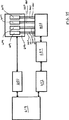
本インターフェース機器は、インターフェース機器の入口と、インターフェース流路、チャンバー、あるいはウェルとの間のアレイ前流体回路と、インターフェース機器の出口と、インターフェース流路、チャンバー、あるいはウェルとの間のアレイ後流体回路とを含んでもよい。ミクロ流体回路は、いくつかのインターフェース流路、チャンバー、あるいはウェル間を直列に連結することによって、提供されてもよい。流体回路には、液体試薬あるいは反応物質の取り扱いステップ、または処理ステップで、種々の流体制御を行うために用いられるバルブ、リザーバ、流体の流れの混合あるいは分割機構、ストップジャンクション、空気吸い込み口、および空気孔などの種々のミクロ流体回路要素を含む。あるいは、またはさらに、アレイ前またはアレイ後処理は、インターフェース機器に接続された1またはそれ以上の分離モジュールによっても達成される。反応物質は、インターフェース機器のミクロ流体回路内、あるいは前処理または後処理モジュールに存在するので、反応または処理ステップは、マイクロアレイ用スライド自体の上だけでなく、これらの構造の中でも行われる。例えば、アレイインターフェースおよび前処理または後処理モジュールは、マイクロアレイ用スライドの処理に用いられるラベリング、プレハイブリダイゼーション、およびハイブリダイゼーションステップを行うことを設定されていてもよい。 The interface device includes a pre-array fluid circuit between the interface device inlet and the interface channel, chamber or well, and a post-array fluid between the interface device outlet and the interface channel, chamber or well. And a circuit. A microfluidic circuit may be provided by connecting several interface channels, chambers, or wells in series. Fluidic circuits include valves, reservoirs, fluid flow mixing or splitting mechanisms, stop junctions, air inlets, and the like that are used to perform various fluid controls in liquid reagent or reactant handling or processing steps. Includes various microfluidic circuit elements such as air holes. Alternatively or additionally, pre-array or post-array processing is also accomplished by one or more separation modules connected to the interface device. Since the reactants are present in the microfluidic circuit of the interface device or in the pre-processing or post-processing module, the reaction or processing steps are performed in these structures as well as on the microarray slide itself. For example, the array interface and pre-processing or post-processing module may be configured to perform labeling, pre-hybridization, and hybridization steps that are used to process microarray slides.
インターフェース機器は、機器の中を流体が通過した後に、余分の流体を収集し、貯蔵することができる。この機器の好ましい態様では、余分の流体は、インターフェース機器の使い捨て部分に収容される。 The interface device can collect and store excess fluid after the fluid has passed through the device. In a preferred embodiment of this device, excess fluid is contained in a disposable part of the interface device.
インターフェース機器は、システム内の流体の動きと、その中で起こる反応の進行をモニターするための電極あるいは他のセンサーを含んでいてもよい。電極は、機器内の溶液中の分子に動電学的な動きを生じさせるために、機器内にも含められていてもよい。加熱エレメントまたは混合機構は、インターフェース機器のいくつかの実施形態に含められる。 The interface device may include electrodes or other sensors for monitoring the movement of fluid in the system and the progress of reactions occurring therein. An electrode may also be included in the instrument to cause electrokinetic movement of molecules in solution in the instrument. A heating element or mixing mechanism is included in some embodiments of the interface device.
インターフェース機器は、少量の流体を処理するためのマイクロメータ単位の構造を加工することが有効な集積回路と、マイクロ電気機械システム(MEMS)と、ミクロ流体システム産業で、用いられる技術に類似するマイクロ加工あるいは他の技術によって、構築される。 Interface equipment is an integrated circuit that is effective in processing micrometer-scale structures for processing small volumes of fluid, micro-electromechanical systems (MEMS), and micro-similar technologies used in the micro-fluid system industry. Built by processing or other techniques.
本発明の好ましい態様では、インターフェース機器と、スライドとは、スライドとインターフェース機器とを支え、安定化し、スライド処理の種々のパラメータを制御し、多数の補助機能を行う基部に置かれている。本発明の最も好ましい態様では、その基部は、複数のスライドを同時に処理する装置の一部である。スライドとインターフェース機器とをクランプする機構は、その基部に組み込まれていてもよい。基部は、スライドとインターフェース機器との間の封止の外部を取り囲む湿潤性チャンバーを含む。加熱又は冷却素子は、反応が種々の温度で行えるように、基部又は機器内に備えられている。基部又は機器は、化学反応を進めるために、インターフェース流路、あるいは可能であればインターフェース機器の他の部位内に、流体の混合又は攪拌機構を含んでいてもよい。本発明の一部の態様では、その機器は、自動スライド処理システムにおいて、同時に処理するために、多数のスライドを支持し、固定することができる。その機器は、本発明の機器によって実行される制御、加熱、冷却、その他の機能のために、マイクロプロセッサ、メモリ、および他の電子機器を含んでいてもよい。本発明の一部の態様では、基部は、基部によって行われる加熱又は混合機能を制御する外部制御モジュールから、離れて形成されている。 In a preferred embodiment of the present invention, the interface device and the slide are located on a base that supports and stabilizes the slide and the interface device, controls various parameters of the slide process, and performs a number of auxiliary functions. In the most preferred embodiment of the invention, the base is part of an apparatus that processes multiple slides simultaneously. A mechanism for clamping the slide and the interface device may be incorporated in the base. The base includes a wettable chamber that surrounds the exterior of the seal between the slide and the interface device. A heating or cooling element is provided in the base or instrument so that the reaction can take place at various temperatures. The base or device may include a fluid mixing or agitation mechanism in the interface flow path, or possibly in other parts of the interface device, to drive chemical reactions. In some aspects of the invention, the device can support and secure multiple slides for simultaneous processing in an automated slide processing system. The equipment may include a microprocessor, memory, and other electronic equipment for control, heating, cooling, and other functions performed by the equipment of the present invention. In some aspects of the invention, the base is formed away from an external control module that controls the heating or mixing function performed by the base.
本発明の目的は、マイクロアレイ用スライドの1又はそれ以上の選択された領域に、制御された流体の供給を提供することにある。これは、適切なインターフェース流路またはウェルの大きさと形とを、選択することによって、達成される。マイクロアレイのいくつかの異なる領域に流体を選択的に供給することにより、多数の異なるサンプルの平行した処理、あるいは同一サンプルの多数の繰り返し処理が同時に実行される複合反応を行うことができる。 It is an object of the present invention to provide a controlled fluid supply to one or more selected areas of a microarray slide. This is accomplished by selecting the appropriate interface channel or well size and shape. By selectively supplying fluid to several different regions of the microarray, a complex reaction can be performed in which multiple parallel processing of different samples or multiple repeated processing of the same sample is performed simultaneously.
本発明の目的は、全ての処理ステップで、極めて少量のサンプルと試薬とを用いて、マイクロアレイ用スライドを処理するための方法とシステムとを提供することにある。これは、インターフェース機器内にミクロ流体的な前処理および後処理回路と、全ての処理ステップが、マイクロ量の流体で行われる附属モジュールとを含むことによって、達成される。試薬とサンプルとの極小量の使用は、コスト効率がよく、サンプルの使用量が制限されている場合に有用なシステムを与える。 It is an object of the present invention to provide a method and system for processing microarray slides using a very small amount of sample and reagent at every processing step. This is accomplished by including microfluidic pre-processing and post-processing circuitry within the interface device and attached modules where all processing steps are performed with micro-volumes of fluid. The use of minimal amounts of reagents and samples is cost effective and provides a useful system when sample usage is limited.
本発明の更なる目的は、同時に少量のサンプルと試薬だけが必要とされている間に、マイクロアレイ表面の流体の混合を行うマイクロアレイ処理方法とシステムとを提供する。これは、新規な気体混合システムにより動く柔軟性の壁部を有する反応チャンバーを用いることによって、達成される。 A further object of the present invention is to provide a microarray processing method and system for mixing fluids on a microarray surface while only a small amount of sample and reagent are required at the same time. This is accomplished by using a reaction chamber with flexible walls that are moved by a novel gas mixing system.
本発明の目的は、泡の発生無しに、マイクロアレイ用スライド上に、インターフェースチャンバーを平坦に充填するための機器を提供する。これは、チャンバーの大きさと形とを適切に選択することによって達成される。たとえ、泡なし充填が、マイクロアレイへの反応物質と試薬の供給がより制限される結果となっても、結果的に、処理済のマイクロアレイからより良い結果が得られる。 It is an object of the present invention to provide an instrument for flatly filling an interface chamber onto a microarray slide without the generation of bubbles. This is accomplished by appropriate selection of the chamber size and shape. Even if bubble-free filling results in more limited supply of reactants and reagents to the microarray, better results are obtained from the processed microarray.
本発明の目的は、サンプルの洩れや喪失なしに、マイクロアレイ用スライドを可逆的に封止するインターフェース機器を提供することにある。可逆的で、漏れのない封止は、インターフェース機器とスライドとの間に適切に選択されたガスケットまたはOリング器具を用いることによって達成される。良い封止体は、マイクロアレイの処理をよりうまく行い、試薬や反応物質の洩れによる実験空間の汚染に伴う問題を小さくする。 An object of the present invention is to provide an interface device that reversibly seals microarray slides without leakage or loss of sample. A reversible, leak-free seal is achieved by using a properly selected gasket or O-ring device between the interface device and the slide. A good seal performs better microarray processing and reduces problems associated with contamination of the experimental space due to leakage of reagents and reactants.
本発明の目的は、前処理および後処理ステップを行うことができる、マイクロアレイ用スライドにインターフェース接続するマイクロアレイインターフェース機器を提供することにある。これは、インターフェース機器内に、ミクロ流体回路が設けられ、処理ステップに要求されるインターフェース機器と流体が通じる付加的な処理前あるいは後処理モジュールが取り付けられていることによって、達成される。全ての処理段階で、本発明のインターフェース機器を用いて行うことにより、スライド処理の簡便性と効率が大きく高められる。 It is an object of the present invention to provide a microarray interface device that interfaces with a microarray slide that can perform pre-processing and post-processing steps. This is accomplished by providing a microfluidic circuit within the interface device and installing additional pre-processing or post-processing modules in fluid communication with the interface device required for the processing step. By using the interface device of the present invention at all processing steps, the simplicity and efficiency of the slide processing is greatly enhanced.
本発明の目的は、マイクロアレイ処理の結果生じた廃棄流体の捕獲と封じ込めを提供することにある。これは、インターフェース流路あるいはウェルの出口に連結されたインターフェース機器内に廃棄物リザーバを設けることによって、達成される。インターフェース機器内に廃棄物を蓄えることにより、廃棄物の収集と廃棄が極めて簡便化され、マイクロアレイ処理の安全性と利便性が改善される。 It is an object of the present invention to provide for capture and containment of waste fluid resulting from microarray processing. This is accomplished by providing a waste reservoir in the interface device connected to the interface flow path or well outlet. By storing waste in the interface device, the collection and disposal of waste is greatly simplified, and the safety and convenience of microarray processing is improved.
本発明の目的は、信頼性のある再生可能な方法で、個々のマイクロアレイ用スライドを手動で処理を行うシステムを提供することにある。これは、手動で供給された試薬と反応性物質とを受け取り、それらを制御された方法で、マイクロアレイ用スライドの表面に提供するインターフェース機器を用いることによって、達成される。 It is an object of the present invention to provide a system for manually processing individual microarray slides in a reliable and reproducible manner. This is accomplished by using interface equipment that receives manually supplied reagents and reactive materials and provides them in a controlled manner to the surface of the microarray slide.
本発明の目的は、自動化された方法で、多数のマイクロアレイ用スライドを同時に処理するシステムを提供することにある。この目的は、望ましい数のスライドを収容するためにマイクロアレイ用スライドの処理システムを多重化することによって、達成される。 It is an object of the present invention to provide a system for simultaneously processing a large number of microarray slides in an automated manner. This object is achieved by multiplexing the microarray slide processing system to accommodate the desired number of slides.
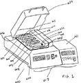
図1は、本発明の目下好ましい実施形態の一例を示す。本発明は、そのそれぞれにマイクロアレイ用インターフェース機器と組み合わされたマイクロアレイ用スライドからなる反応機器604を支持するために適合する多数の張間602を含む装置600を含む。張間602は、装置600のウェル608にはめ込まれている加熱ブロック606上の基部603に位置する。基部603は、加熱ブロック606の一部として形成される、あるいは別個に形成され、加熱ブロック606上に搭載される。いずれの場合でも、基部603と張間602とは、加熱ブロック606と熱伝達されている。反応機器604は、マイクロアレイ処理の間、加熱ブロック606によって、加熱されている。各々の反応機器604は、空の張間602に見えるエアコネクタ609と610とに結ばれている。エアコネクタ609と610とは、装置600の動力源に接続されており、反応機器604中で流体の混合に用いられる。図1に示される本発明の実施形態では、サンプル、試薬、および洗浄液は、入口孔612を通して、各々の反応機器へ導入され、空気あるいは液体は、出口孔614を通して、反応機器を出る。入口孔612と出口孔614とは、インターフェース機器616中に形成され、マイクロアレイスライド用ガラスの表面上の反応チャンバーと流体的に接続する。コントロールパネル618は、ユーザが、例えば加熱ブロック温度や混合パラメータなどの装置600によって行われる種々の機能を制御することを可能にする。この特別な例では、装置600は、試験管やエッペンドルフ用チューブなどを加熱するために用いられる型の市販の実験用ヒータ620と、ポンプユニット620から構成されているので、機器の一部であるポンプユニット621と加熱ブロック606とは、実験用ヒータ620とは別個に製造されることができる。ポンプユニット620は、多岐管622によって、各々の反応機器のエアラインコネクタ609と610に、空気を交互に出し入れする。ポンプと加熱ユニットとが同一の装置容器中に作られている装置によっても、同様の機能が得られる。光は、マイクロアレイ処理の間に一般に用いられる色素を退色させるので、装置600には、マイクロアレイ用スライドが光にさらされることを防止するために、不透明な蓋624を含んでいてもよい。蓋624は、熱の絶縁体をも提供する。
FIG. 1 shows an example of a presently preferred embodiment of the present invention. The present invention includes an
図2は、反応機器604の分解立体図である。図1との関連で述べたように、反応機器604は、マイクロアレイ用スライド150に封止されているインターフェース機器616を含む。この例では、インターフェース機器616は、主インターフェース層617とガスケット404とから構成されている。反応チャンバーは、スライド150の上側表面と、主インターフェース層617の下側表面との間に形成され、反応チャンバーの境界は、ガスケット404中の開口部406で定義される。流体は、入口612を通って、反応チャンバーへ注入される。流体が注入されると、反応チャンバー内に既に存在している空気あるいは流体は、出口614を通って、流出する。反応チャンバーは、マイクロアレイ154中のスライドにスポットされた物質と流体の相互作用を許す。浮袋628と629とは、主インターフェース層617の内部に形成され、それぞれが、空気流路634と635を介してコネクタ631と632とに接続されている。コネクタ631と632とは、反応機器604が、装置600の空気路コネクタ609と610と接続することを可能にする。浮袋628と629の下表面は、薄くて、柔軟性があるので、浮袋628と629の圧力が、増加するまたは減少するにしたがって、浮袋628と629は、下向きあるいは上向きにゆがむ。主インターフェース層617の下側の表面は、主インターフェース層617の大部分を形成するより堅い材料に付着している、薄くて、柔軟性がある材料の膜で形成され、あるいは主インターフェース層617の下側の表面は、薄さによって与えられた柔軟性を持つ主インターフェース層617の残りの材料と同一の材料で形成されてもよい。この場合に、主インターフェース層617の内部に隙間のある構造を形成するために、主インターフェース層617は、種々の標準的な製造方法により、お互いがくっついた1またはそれ以上の層で形成されることができる。インターフェース機器616と、スライド150とは、スライド150を基部402中の凹部400に置き、(底面に取り付けられたガスケット404を含む)インターフェース機器606をスライド150上に置き、例えば、ピン422と、423上を内側に枢軸回転するC−溝クランプ418と、420のようなクランプ機構によって、全てをお互いに固定することによって、固定される。
FIG. 2 is an exploded view of the
図3は、反応機器604の断面図を示す。ガスケット404は、反応チャンバー640を形成するために、主インターフェース層617をマイクロアレイ用スライド150に封止する。流体は、入口612を通って、反応チャンバー640に入り、流体が入るに従って、空気が、出口614を通って、流出する。浮袋628と629とは、反応チャンバー640の両端上に位置してはいるが、反応チャンバー640とは通じていない。反応チャンバー640中で、流体を攪拌するためには、一つの浮袋(例えば、浮袋628)は、下側表面643を反応チャンバー640の方へ下方にゆがめるために加圧させ、他方の浮袋(例えば、浮袋629)は、下側表面642を上方にゆがめるために減圧させる。相反なやり方で、ふたつの浮袋を交互に膨張し、収縮することによって、混合を起こすために十分な流体の動きが、反応チャンバー640内で、発生する。陽圧と陰圧とは、空気流路634を介して浮袋628に、空気流路635を介して浮袋629に与えられる(図示せず)。反応チャンバー640の高さは、ガスケット404の厚さによって、規定される。本発明の好ましい形態では、ガスケット404は、少なくとも約15μm、多くても約300μmの厚さであり、より好ましくは少なくとも約20μm、多くても約30μm、さらに好ましくは少なくとも約23μm、多くても約27μm、最も好ましくは約25μmである。ガスケットの厚さが減少するにつれて、スライド表面とインターフェース機器の下方表面の荒れ、およびガスケットの不均一性が問題となる。そのうえ、ガスケットの厚さがさらに減少すると、チャンバーは、満たすことが困難となる。それゆえ、反応チャンバーを小さい容積にすることが好ましいが、もし、高さが一定の高さ以下になると、チャンバーの高さを減少することによる容積の減少が問題を起こすことは明らかである。チャンバーの容積は、ガスケット404の開口部406の大きさを変えることによっても減少できる。もし、ガスケット404の開口部406が、市販のスッポッティング装置により典型的に形成される最大のマイクロアレイの周囲に適合するのであれば、多くとも36μlから54μlの、より好ましくは41μlから49μlの、最も好ましくは45μlの容積の反応チャンバーが得られる。もし、反応チャンバー604が、より小さなマイクロアレイ(あるいは部分的なマイクロアレイ)を収容することを許容するのであれば、開口部406は、チャンバー容積の減少を伴って、かなり小さくすることができる。
FIG. 3 shows a cross-sectional view of the
図2と3とは、マイクロアレイ用スライドの表面に単一の反応チャンバーを形成するインターフェース機器を示す。しかし、本発明によれば、種々の形体を有する反応チャンバー、流路、およびウェルが、マイクロアレイ用スライド上に形成されることができる。以下の例は、インターフェース機器によって形成される反応チャンバー、流路、およびウェルの重要な特徴をより明確に説明する。 2 and 3 show an interface device that forms a single reaction chamber on the surface of a microarray slide. However, according to the present invention, reaction chambers, flow paths, and wells having various shapes can be formed on the microarray slide. The following example more clearly illustrates the important features of the reaction chamber, flow path, and well formed by the interface device.
図4は、お互いが封止される前のマイクロアレイ用スライド1とインターフェース機器3とを示す。マイクロアレイ用スライド1は、平面基板9の表面7のスポットアレイ6に配列された多数のスポット5を含む。スポット5は、表面7に固定された生体分子、または他の反応材料で形成される。平面基板は、通常ガラス製の顕微鏡用スライドが用いられるが、他の材料で作られた基板や他の大きさのものを用いてもよい。本発明は、特別な基板に限定するものではないが、インターフェース機器が、用いられるどのような基板の表面に対して封止されることが、必要とされる。スポットアレイ6は、ピンスポット法、インクジェット技術、あるいは基板上での分子の選択成長によるなどを含む種々の方法によって、形成される。
FIG. 4 shows the
図4に示すようにスポットアレイ6中のスポットは、縦列11と横列12とに規則的に間を開けて、配列されている。この例では、簡単のため、各々が10個のスポットを含む4個の縦列が用いられている。実際には、マイクロアレイは、通常もっとスポットの数が多いが、本発明は、スポットの特定の数に限定されるものではなく、スポットの特定の配列に限定されるものではない。特定のスポットを参照するためには、横列と縦列との配列が容易で、簡便なため、アレイのパターンが用いられているが、本発明では、基板の大きさと、検出またはモニターステップの間に個々のスポットを視覚化するために必要とされる最小限のスペースという限定があるのみで、アレイ、あるいは1個から、非常に多数のスポットまでを、どこにでも含む他のパターンのスポットとインターフェース接続するために使用されることができる。さらに、インターフェース機器3は、生体分子あるいは反応物質が、スポットに局在しているのではなく、他の組分けに配列するまたは基板9の表面7にかなり一様に分配された基板9に用いられることができる。
As shown in FIG. 4, the spots in the spot array 6 are arranged in the column 11 and the
一定の使用では、インターフェース機器を、マイクロアレイ用スライド上に1またはそれ以上の、全部のスポットのマイクロアレイに接近するために用いることが好ましい。図25および27に示すように、マイクロアレイ用スライド上のスポットのアレイ154は、マイクロアレイ用スライド150のインターフェースと主インターフェース層144とで、形成された1または数個の完全−アレイ反応チャンバー230によって、接近されている。反応チャンバー230の形と高さは、ガスケット146によって規定される、あるいは反応チャンバーは、主インターフェース層の最下部表面にまでも、拡張することができる。流体が、反応チャンバーに導入されるに従って発生する、泡を最小にするために、図26に示すように、反応チャンバーが段階的断面を有することが好ましい。泡の形成なしに、滑らかで、均一で、充填された反応チャンバーは、流体の入口で、比較的狭く、反応チャンバー230の全幅に向かって、徐々に外側に広がることにより、得られる。同様に、反応チャンバー239は、出口で徐々に狭くなる。もし、疎水性の材料が、マイクロアレイ用スライド150と、主インターフェース層144に用いられ、流体が、反応チャンバー230のより大きな端の入口から導入されれば、流体は、ライン231と232との間の反応チャンバー239のわずかに浅い領域に入る前に、入口とライン230の間の全体領域に充填されるように広がる傾向がある。同様に、ライン231と232との間の領域は、ライン232と233との間のさらに狭い領域に入る前に、充填される傾向がある。このことは、泡の形成につながる不規則な充填パターンを減少させる。もし、親水性の材料を用い、同様の段差のある反応チャンバー構造が用いられるが、親水性の材料であるため、流体が反応チャンバーの狭い端で導入されれば、より強い毛管力により、より狭い領域が、最初に充填されるだろう。段差があるよりもむしろ徐々に傾斜する側面の反応チャンバーは、実質上同じ態様で、機能する。
For certain uses, the interface instrument is preferably used to access one or more microarrays of all spots on a microarray slide. As shown in FIGS. 25 and 27, an array of
マイクロアレイ用スライドの大部分に接近するためのインターフェース機器の他の例が、図30に示される。本発明のこの形態では、マイクロアレイ用スライド150は、基部402の凹部400にはめ込まれ、ガスケット404は、開口部406がマイクロアレイ154を含む反応チャンバーを形成するように、マイクロアレイ用スライド150上に好ましく置かれており、インターフェース機器408は、ガスケット404上に位置するので、入口流路410と出口流路412とは、インターフェース機器408とマイクロアレイ用スライド150との間に形成され、ガスケット404中の開口部によって仕切られた反応チャンバー413と通じている。ピン422と423とによって、基部402上に枢軸回転可能に搭載されている枢軸回転C−溝クランプ部材418と420とは、基部402と、マイクロアレイ用スライド150と、ガスケット404と、インターフェース機器408によって形成される“サンドイッチ”の端の上に滑り込むために内側に開閉する。クランプ部材418と420とは、C−溝の断面に線状であり、金属、プラスチック、その他の堅い材料で、形成されることができる。もし、適正に選択されたガスケット材料が用いられれば、マイクロアレイ用スライド150と、ガスケット404と、インターフェース機器408の良好な封止が、大きな圧力をかけることなしに、得られる。我々は、効果的な封止が、ガスケットを、ブタジエン、低分子量ポリエチレンとパラフィン蝋、およびアメリカン キャン カンパニーによって販売されているパラフィルムMTMから構成される柔軟性のある熱可塑性フィルムで形成することで得られることを見出した。他の適した代替できるガスケット材料は、MJリサーチ インク、ウォルザム、MAにより販売されているワックスシート材料のMJフィルムTMである。これらの材料は、圧縮される場合に、すなわち弾性というよりむしろ本質的に可塑性の変形を被る。ひとたび、ガスケットが、クランプ部材418と42とによって、圧力が掛けられることによる変形(圧縮)されると、マイクロアレイ用スライド150と、ガスケット404と、インターフェース機器408とのシステムは、かなりの圧力下ではないが、封止され、一つにまとまる。ガスケット404は、シリコンゴムのような、弾性材料で形成されていてもよいし、分離した構成部材で、形成されていてもよいし、あるいはスクリーン印刷、プリント印刷などによって、インターフェース機器408の底面に直接適用されていてもよい。
Another example of an interface device for accessing the majority of microarray slides is shown in FIG. In this form of the invention, the
図25〜27に示される本発明の実施形態に関連して、先に述べたように、反応チャンバーは、入口端425と出口端426で狭く、スムーズに、泡の形成なしに充填し、空にするために、外側に向かってなだらかに曲がっている。ガスケット404の圧縮量は、基部の表面あるいはガスケット404に近接したインターフェース機器408の表面に形成された既知の厚さを持つ絞りまたは詰め木(図示せず)によって、または機械加工により、あるいはスクリーン印刷または他の方法で材料の薄膜を適用することにより、制御される。絞りまたは詰め木を特定の厚さで形成することにより、反応チャンバー413の高さ(と、それゆえ、容積)を制御することができる。
In connection with the embodiment of the present invention shown in FIGS. 25-27, as described above, the reaction chamber is narrow at the
図30に示す例では、基部402の凹部400は、マイクロアレイ用スライド150の配置や除去を容易にするために、その隅に、指状拡大部428を含む。廃棄物リザーバ430は、インターフェース機器408の上側表面に備えられている。蛇行封止部432は、空気は逃すが、流体は逃さない。廃棄物リザーバ430と蛇行封止部432とは、種々の方法(エポキシ樹脂、ヒートシールなど)によって、インターフェース機器408に封止されていてもよい、キャップ434によって覆われている。キャップ434中の空気孔436は、空気を逃すために、蛇行封止部432の端431につながっている。例えば、疎水性膜やキャピラリーチューブのような、種々の代替構造が空気を許容するために使用される。マイクロアレイ用スライド表面に流体を容易に供給するための少量反応チャンバーを提供するために、図30の機器は、独立した機器として使用でき、図1に示すように、装置と接続して使用する必要はない。図30の機器は、空気を混合するための、浮袋を含まない。
In the example shown in FIG. 30, the
本発明の別の実施形態としては、基部402とインターフェース機器408との間に耐水性の封止部を形成するために、ガスケット、o−リング、あるいは他の封止手段を含めることにより、凹部400は、湿潤性チャンバーとして、構成されてもよい。基部402とインターフェース機器408とを(凹部400中に位置するマイクロアレイ用スライド150とともに)封止する前に、適切な流体を凹部400に加えることで、反応チャンバー413から流体の蒸発を妨げるための、湿潤環境が、マイクロアレイ用スライド150とインターフェース機器408との間の封止部の周囲に作り出される。
Another embodiment of the present invention is to include a recess by including a gasket, o-ring, or other sealing means to form a water-resistant seal between the base 402 and the
基部402は、マイクロアレイ処理の間に加熱および混合機能を提供する構造を含んでいてもよい。
場合によっては、新規なインターフェース機器を、マイクロアレイ用スライドの特定の場所に選択的に接近するために、使用することが望ましい。図4は、マイクロアレイの個々の縦列に、流体が供給されることを許す発明の実施形態を示す。図4では、インターフェース機器3は、マイクロアレイ用スライド1の表面7、上表面15、側面17と19、端面21と23とに対向して適合するように適応されたインターフェース表面13を有する。インターフェース表面13は、分割壁27によって分離され、外壁29によって境をなされているスポットアレイ6の縦列11に相当する平行な溝25を含んでいる。溝25は、入口流路33によって、インターフェース入口31に、出口流路37によってインターフェース出口35に接続されている。
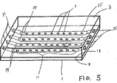
In some cases, it may be desirable to use a new interface device to selectively access a specific location on the microarray slide. FIG. 4 shows an embodiment of the invention that allows fluid to be supplied to individual columns of the microarray. In FIG. 4, the
図5に示すように、インターフェース表面13が、マイクロアレイ用スライド1の表面に対向して押し付けられた場合には、閉鎖されたインターフェース流路39を形成するために、溝25は、表面7によって、閉じられるか、覆われる。本発明のこの実施形態では、各々のインターフェース流路39は、スポット5の縦列を含む。インターフェース機器3のインターフェース入口31とインターフェース出口35は、インターフェース流路39に通路を提供する。
As shown in FIG. 5, when the interface surface 13 is pressed against the surface of the
図6は、マイクロアレイ用スライド1上のスポット5と、インターフェース流路39と、入口流路33と、出口流路37と、インターフェース入口31と、インターフェース出口35とを含むインターフェース機器3の平面図を示す。この例では、流体サンプルは、インターフェース入口31に入り、インターフェース流路39を通り抜け、スポット5上を進み、インターフェース出口35を通り、インターフェース機器を出る。
FIG. 6 is a plan view of the
図4〜6に示される発明の実施形態では、スポット5の縦列11が、個々に接近されることを許容する。サンプル、試薬、あるいは他の反応物質の連続的な流れが、各々のスポットの縦列に供給されることができる。これらの図に示すように、入口流路33と出口流路37とは、インターフェース機器3の内部に形成された閉鎖流路である。入口流路33と出口流路37とは、インターフェース機器3が、マイクロアレイ用スライド1に封止されたときに、同時に閉鎖流路を形成する、溝25とつながった、インターフェース機器3のインターフェース表面中の開放された溝として形成することもできる。入口流路33と出口流路37とを形成する2つの代替方法が、図7と8に示されている。図7に示す実施形態では、入口流路33と出口流路37とは、インターフェース流路39に垂直に形成され、インターフェース入口31とインターフェース出口37とは、インターフェース機器の上方表面15にある。図8に示す実施形態では、マイクロアレイ用スライドを収容するための大きさの凹部41がインターフェース機器3内に形成されている。入口流路33と出口流路37とは、インターフェース流路39に平行に、連続して形成され、インターフェース入口31とインターフェース出口35とは、インターフェース機器3の端部にある。インターフェース入口31とインターフェース出口35とは、図7と8に示されるような外部の配管へ接続するためのねじ山42、または当該分野の当業者によく知られている他の型のコネクタを含む。本発明の他の実施形態においても、同様に、インターフェース入口31とインターフェース出口35とは、ねじ山が付けられているか、他の型のコネクタを含む。
In the embodiment of the invention shown in FIGS. 4-6, the columns 11 of
図9は、アレイ前ミクロ流体回路が、インターフェース入口31とインターフェース流路39との間に含まれ、アレイ後ミクロ流体回路が、インターフェース流路39とインターフェース出口35との間に含まれている本発明の代替可能な2次元的な実施形態を示す。この例では、アレイ前ミクロ流体回路は、単一のインターフェース入口31を通って、個々のインターフェース流路39に、流体を供給される4個のアレイ前流路49、50、51と52に入れるために、流体を分割する分岐点47を含む。アレイ後ミクロ流体回路は、4個のアレイ後流路53、54、55と56を介して複数のインターフェース流路39の出力を受け取り、それらを、単一のインターフェース出口35を介してインターフェース機器3を流出する単一の出力の流れを形成する結合点57で結合して一体にする。
FIG. 9 shows a book in which a pre-array microfluidic circuit is included between the
図9に示す例では、アレイ前ミクロ流体回路は、単一の流体の流れを複数の流体の流れに分割するという単純な仕事を行い、一方、アレイ後ミクロ流体回路は、単一の流体の流れを形成するために、複数の流体の流れを加算する。しかし、アレイ前およびアレイ後ミクロ流体回路は、当該分野でよく知られている、あるいは、後に開発されるミクロ流体的方法や構造を用いて、さらに複雑な処理を行ってもよい。アレイ前およびアレイ後ミクロ流体回路は、特別な適用の要求により、どのような数の入口と出口とを有してもよい。 In the example shown in FIG. 9, the pre-array microfluidic circuit performs the simple task of splitting a single fluid flow into multiple fluid flows, while the post-array microfluidic circuit is a single fluid flow. Add multiple fluid flows to form a flow. However, pre-array and post-array microfluidic circuits may be more complex using well-known or later developed microfluidic methods and structures. The pre-array and post-array microfluidic circuits may have any number of inlets and outlets, depending on the requirements of the particular application.
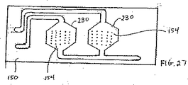
1つのマイクロアレイ中の、個々のスポットまたはスポット群に、選択的に接近するために用いられる、本発明の三次元的な実施形態が、図10に示されている。複数の個々のスポット、あるいは(縦列の配列または他の配列の限定された数のスポットとは異なる)複数の別個のスポット群は、図1〜9に示すような実質的に平面、あるいは“二次元的な”インターフェース機器では、入口および出口流路と、ミクロ流体回路が重複するため、容易に接近できない。入口および出口流路をインターフェース機器構造の異なる面または段に移動することにより、異なるスポットへのより選択的な接近が可能となる。3Dインターフェース機器60は、基板9上の単一のスポット70、72、74、76への接近を提供する反応チャンバー62、64、66、68、およびマイクロアレイ用スライド1上のスポット群80、81、82、83への接近を提供する反応チャンバー78とを含む。インターフェース入口85、86、87、88は、流体が流路90、91、92、93を介して、反応チャンバー62、64、66、68にそれぞれ注入されることを可能にする。インターフェース入口94は、流体が流路95を介して、反応チャンバー78に提供されることを可能にする。流路96、97、98、99は、流体を、反応チャンバー62、64、66、68から、インターフェース出口100、101、102、103に、それぞれ運ぶ。それゆえ、個々のスポット70、72、74、76は、直接流水式で、単一の流体の流れにより、個々に接近されうる。逆に、反応チャンバー78からの流路105は、流体の流れを、流路105から、リザーバ110、111、112に導く3個の分岐107、108、109に、進路を変える分岐点106と、インターフェース出口100、101、102、103を介して、リザーバ110、111、112から空気あるいは他のガスを逃すことを考慮する空気排気流路113、114、115とから構成されるアレイ後ミクロ流体回路に導く。分岐点106のバルブ117は、分岐107、108、109への流体の流れを制御し、リザーバ110、111、112の出口のストップジャンクション119は、リザーバからの流体の流れを妨げるが、空気の流れを妨げない。このアレイ後ミクロ流体回路は、DNA処理に用いられる回路の型を表す。
A three dimensional embodiment of the present invention used to selectively access individual spots or groups of spots in a microarray is shown in FIG. Multiple individual spots or groups of discrete spots (as opposed to a limited number of spots in a tandem or other arrangement) can be substantially planar as shown in FIGS. In a “dimensional” interface device, the inlet and outlet channels and the microfluidic circuit overlap and are not easily accessible. Moving the inlet and outlet channels to different faces or steps of the interface device structure allows for more selective access to different spots. The
図10に示される3Dインターフェース機器は、本発明の多くの重要な特徴を説明する。3Dインターフェース機器は、複数の個々のドット、あるいは縦列でないドットの集団とインターフェース接続できることを示す。インターフェース入口、ウェル、インターフェース出口に接続する多数の双方の流路は、2Dあるいは平面構造より、3D構造に含まれ、(アレイ前、後のいずれか、または両方の)ミクロ流動回路は、インターフェース機器内に含まれ、望ましくはアレイ上に位置する。3D構造に十分な数の層を含むことにより、マイクロアレイ中の全てのスポットに個々に接近することが可能であり、好ましくはインターフェース機器内に多様なミクロ流体回路を含むことが可能である。 The 3D interface device shown in FIG. 10 illustrates many important features of the present invention. The 3D interface device indicates that it can interface with a plurality of individual dots or a group of non-tandem dots. A number of both flow paths connecting to the interface inlet, well, and interface outlet are included in the 3D structure rather than in the 2D or planar structure, and the microfluidic circuit (either before, after, or both) is connected to the interface device. Contained within, preferably located on the array. By including a sufficient number of layers in the 3D structure, it is possible to individually access all the spots in the microarray, and preferably include various microfluidic circuits within the interface device.
本発明のインターフェース機器は、マイクロアレイ中の個々のスポットあるいはスポット群を1またはそれ以上のミクロ流体回路に組み込むことができる。これは、スポットの処理に種々のミクロ流体的な方法の使用を許す。図1〜10で示される例は、ミクロ流体回路のいくつかの例を含む。しかし、本発明のインターフェース機器は、マイクロアレイ上のスポットを処理するために望まれる他の型のミクロ流体回路を含んでいてもよく、本発明は、ここで示したミクロ流体回路に限定されるものではない。インターフェース機器内で形成されるこの型のミクロ流体回路の構成要素は、分岐、接点、バルブ、ストップジャンクション、リザーバを含むが、これらに限定されるものではない。ミクロ流体回路は、流体の流れを混合または分割するための構造、および特別な流路、ウェル、あるいはリザーバへの流体の流れの出し入れを開始及び終了するための構造を含んでいてもよい。 The interface device of the present invention can incorporate individual spots or groups of spots in a microarray into one or more microfluidic circuits. This allows the use of various microfluidic methods for spot processing. The examples shown in FIGS. 1-10 include several examples of microfluidic circuits. However, the interface device of the present invention may include other types of microfluidic circuits desired for processing spots on the microarray, and the present invention is limited to the microfluidic circuits shown herein. is not. The components of this type of microfluidic circuit formed within the interface device include, but are not limited to, branches, contacts, valves, stop junctions, and reservoirs. The microfluidic circuit may include structures for mixing or splitting fluid flows and structures for initiating and terminating fluid flow to and from special channels, wells, or reservoirs.
流体は、動電学的、電気流体力学的、および加圧を含む多数の方法により、ミクロ流体回路の中に入り、ミクロ流体回路を通過する。もっとも好ましい選択は、溶液がイオン性かどうかに関わらず、関与する流速と、マイクロアレイ用基板とインターフェース機器に用いられる材料の種類による。ミクロ流体回路内の流体の受動制御は、流体の特定の物質に対する引力または斥力によって起こる毛管現象を活用することによっても、可能になる。一般に、所有する2001年10月2日発行のUS特許6,296,020号では、本発明に用いるに適した疎水性のパッシブバルブの調整に基づく多くのミクロ流体回路構造が開示されている。しかし、他の型のミクロ流体回路の構成要素もまた、用いることができ、本発明は、特別な型のミクロ流体回路に限定されるものではない。 The fluid enters and passes through the microfluidic circuit in a number of ways, including electrokinetics, electrohydrodynamics, and pressurization. The most preferred choice depends on the flow rate involved and the type of material used for the microarray substrate and interface equipment, regardless of whether the solution is ionic. Passive control of the fluid in the microfluidic circuit is also possible by exploiting the capillary action that occurs due to the attraction or repulsion of the fluid to a particular substance. In general, US Pat. No. 6,296,020 issued Oct. 2, 2001, owned, discloses a number of microfluidic circuit structures based on the adjustment of hydrophobic passive valves suitable for use in the present invention. However, other types of microfluidic circuit components can also be used, and the invention is not limited to a particular type of microfluidic circuit.
機械的バルブ、疎水性流体経路の狭小化やキャピラリーバルブのようなパッシブバルブを含む種々の型のバルブがアレイ前、アレイ後ミクロ流体回路に含められることができる。回路の特定の領域における空気の排気を制御する、それゆえ流体の動きに対抗する背圧を調節するための外部バルブを用いて、流体の流れを制御する遠隔バルブ調整もまた、用いられてもよい。遠隔バルブ調整の方法とシステムとは、ここで参考文献によって加えられる、一般に所有するPCT公開公報WO 02/12734に開示されている。 Various types of valves can be included in the pre-array and post-array microfluidic circuits including mechanical valves, hydrophobic valve narrowing and passive valves such as capillary valves. Remote valve adjustments that control fluid flow using external valves to control the exhaust of air in specific areas of the circuit and thus to adjust the back pressure against fluid movement may also be used. Good. A remote valve adjustment method and system is disclosed in commonly owned PCT publication WO 02/12734, hereby incorporated by reference.
空気排出流路と停止手段とが、流体回路内に含まれていてもよい。圧力がかかった流れを最も活用する場合では、ミクロ流体回路は、移動する流体によって置き換えられた空気が、回路から出ることを許容するために、移動する流体の下流の1またはそれ以上の点で、大気に開放されている。これは、望ましい流体の流れに対抗し得る無用な圧力の蓄積を阻止する。空気は流出するが流体は保たれるキャピラリーバルブ、多孔性の疎水性膜、あるいは同様の方法を用いることによって、流体が、空気強制排気流路を通って、回路から流出することが妨げられる。上記したように、空気の流出を調節することは、回路内の流体の動きを制御することに用いられる。 The air discharge flow path and the stop means may be included in the fluid circuit. In most cases where pressured flows are utilized, the microfluidic circuit is one or more points downstream of the moving fluid to allow air displaced by the moving fluid to exit the circuit. , Open to the atmosphere. This prevents unnecessary pressure buildup that can counter desired fluid flow. By using capillary valves, porous hydrophobic membranes, or similar methods that allow air to escape but retain fluid, fluid is prevented from exiting the circuit through the air forced exhaust flow path. As described above, adjusting the outflow of air is used to control fluid movement in the circuit.
本発明によるインターフェース機器は、ガラス、シリコン、またはPTFE、FEP、PFA、PET、PMAA、あるいはPCなどのある種のプラスチックで、形成されることが好ましい。インターフェース機器の2次元および3次元ミクロ流体回路は、微小リソグラフィ、化学エッチング、薄膜真空蒸着、熱エンボス加工、微量注入成形、あるいはIRおよびUVレーザの両方を用いるレーザ加工を含む種々の方法により、形成される。 The interface device according to the invention is preferably made of glass, silicon or some plastic such as PTFE, FEP, PFA, PET, PMAA, or PC. Interface equipment 2D and 3D microfluidic circuits are formed by a variety of methods including microlithography, chemical etching, thin film vacuum deposition, hot embossing, microinjection molding, or laser processing using both IR and UV lasers. Is done.
ミクロ流体回路の流路、ウェル、リザーバ、バルブ、および他の構成要素は、一般に、インターフェース機器を構築するために用いられる1つの材料の表面に容易に形成されるが、1つの固体材料の内部に形成するのは、容易ではない。それゆえ、インターフェース機器内に位置する回路の構成要素を形成するため、および多重層(3D)構造を形成するためには、インターフェース機器は、多重の層で形成されていてもよい。例えば、開放された流路(溝)あるいはウェルが、第1層に形成され、第2層は、流路あるいはウェルを閉じる上面を形成するために、第1層に封止される、あるいは固定される。個々の層は、三次元的な、多層構造を形成するために整列され、封止される。封止方法は、接続される材料に依存するが、共晶接合またはアノード接合、接着剤やエポキシ樹脂系接着剤の使用、あるいは超音波溶接を含めてもよい。まっすぐな流路が、外部表面(例えば、図4、7、8の流路31、35)からインターフェース機器の内部を貫通する場合には、流路は、インターフェース機器の外部から、機械加工またはエッチングをすることによって、形成されることができる。
Microfluidic circuit flow paths, wells, reservoirs, valves, and other components are generally easily formed on the surface of one material used to construct an interface device, but inside one solid material It is not easy to form. Therefore, in order to form circuit components located within the interface device and to form a multi-layer (3D) structure, the interface device may be formed of multiple layers. For example, an open channel (groove) or well is formed in the first layer, and the second layer is sealed or fixed to the first layer to form an upper surface that closes the channel or well. Is done. The individual layers are aligned and sealed to form a three-dimensional, multilayer structure. The sealing method depends on the material to be connected, but may include eutectic bonding or anodic bonding, use of an adhesive or an epoxy resin adhesive, or ultrasonic welding. If a straight channel passes through the interior of the interface device from an external surface (eg,
流体制御技術の中には、流体回路の一部に電気的な接近を要求するものもある。例えば、動電学的流体制御および電気流体力学的流体制御は、いずれも流体回路内の流路およびバルブに取り付けられた電極を利用する。インターフェース機器構造内に加熱エレメントを含めることが好ましい場合もある。機械的なバルブ、ポンプ、あるいは加熱エレメントのいずれもが、電気的なインターフェース方式を必要とする。もし、これらの制御エレメントが、多重層システム内に埋め込まれている場合には、回路をコントロールするために接続されるための電気的な痕跡が、インターフェース機器の外部にもたらされなければならない。このような付加的な構成要素の全ては、本発明の範囲内にあると考えられる。 Some fluid control technologies require electrical access to a portion of the fluid circuit. For example, electrokinetic fluid control and electrohydrodynamic fluid control both utilize electrodes attached to flow paths and valves in the fluid circuit. It may be preferable to include a heating element within the interface device structure. Any mechanical valve, pump, or heating element requires an electrical interface scheme. If these control elements are embedded in a multilayer system, electrical traces to be connected to control the circuit must be provided outside the interface device. All such additional components are considered to be within the scope of the present invention.
インターフェース機器は、疎水性材料または親水性材料のいずれでも形成されることができるが、多くの場合では、機器の一部または全部に疎水性材料を用いることが好都合である。親水性材料は、その外観の大きさに反比例する毛管力を発生する。それゆえ、それゆえ、親水性多重層構造の小さな割れ目は、親水性キャピラリーシステムを一般的に不安定にする巨大な毛管力を発生することがある。液体は、疎水性流路に引き込まれず、加圧下で、駆動されるので、疎水性材料で形成された構造や、疎水性キャピラリーバルブを使用する構造は、良好に流体の流れを制御することができる。さらに、インターフェース機器のインターフェース表面は、マイクロアレイ用基板の表面に密接に適合し、マイクロアレイ用基板の表面を封止する。もし、インターフェース機器が、疎水性材料で形成される、あるいは疎水性の表面被覆物を有すれば、インターフェース機器と基板間との水性溶液の漏出は、最小限になるだろう。適切な疎水性の材料は、PTFE、FEP、PFAを含む。インターフェース機器は、シリコン、ガラス、PET、PMMA、またはPCのような非疎水性の材料で、構築してもよく、必要に応じて、疎水性材料の真空蒸着技術、回転塗布、あるいは蒸着により、疎水性の被覆物が、親水性材料の上に形成されることもできる。 The interface device can be formed of either a hydrophobic material or a hydrophilic material, but in many cases it is advantageous to use a hydrophobic material for some or all of the device. Hydrophilic materials generate capillary forces that are inversely proportional to the size of their appearance. Therefore, small cracks in the hydrophilic multilayer structure can generate enormous capillary forces that make the hydrophilic capillary system generally unstable. Since the liquid is not drawn into the hydrophobic flow path and is driven under pressure, a structure formed of a hydrophobic material or a structure using a hydrophobic capillary valve can control the flow of the fluid well. it can. Furthermore, the interface surface of the interface device closely matches the surface of the microarray substrate and seals the surface of the microarray substrate. If the interface device is formed of a hydrophobic material or has a hydrophobic surface coating, leakage of the aqueous solution between the interface device and the substrate will be minimal. Suitable hydrophobic materials include PTFE, FEP, PFA. The interface device may be constructed of a non-hydrophobic material such as silicon, glass, PET, PMMA, or PC, optionally by vacuum deposition technique, spin coating, or vapor deposition of the hydrophobic material, A hydrophobic coating can also be formed on the hydrophilic material.
インターフェース機器と、マイクロアレイ用スライドとの間に封止体を提供するために用いられるガスケットは、シリコン、独立気泡フォーム、またはゴムのような弾力性の材料、または、例えばシリコンで被覆されたPTFEまたは他のプラスチックのような弾力性の材料で、被覆されたより弾力性の少ない材料で、形成されてもよい。我々は、他の適したガスケット材料が、ブタジエンと、低分子量ポリエチレンとパラフィン蝋と、およびアメリカン キャン カンパニーによって販売されているパラフィルムMTMから構成される柔軟性のある熱可塑性フィルムで形成することで得られることを見出した。他の適した代替できるガスケット材料は、MJリサーチ インク、ウォルザム、MAにより販売されているワックスシート材料のMJフィルムTMである。これらの材料は、本質的には、弾力性というよりむしろ、可塑性である。用いられる他の封止構造は、弾力性または可塑性の材料のo−リング、またはインターフェース機器またはスライド上に封止剤材料を、塗布される、あるいは直接形成される層を含む。インターフェース機器のマイクロアレイ用スライドへの封止は、粘着性の“ガスケット”層を使用することにより、達成され、この場合では、封止部を得るために、スライドとインターフェース機器を共に固定する必要はない。しかし、接着剤によって与えられる結合強度を増加するために、固定機能を伴って、クランピングと粘着層とを共に与えるほうが効果的な場合もある。 The gasket used to provide the seal between the interface device and the microarray slide is a resilient material such as silicone, closed cell foam, or rubber, or PTFE coated with silicone or It may be formed of a less resilient material coated with a resilient material such as other plastics. We other suitable gasket material, butadiene and, be formed of a thermoplastic film with a flexible comprised Parafilm M TM sold and a paraffin wax low molecular weight polyethylene, and the American scan Company I found out that Another suitable alternative gasket material is MJ Film ™, a wax sheet material sold by MJ Research Inc., Walzam, MA. These materials are essentially plastic rather than elastic. Other sealing structures that are used include o-rings of resilient or plastic materials, or layers on which sealant material is applied or directly formed on an interface device or slide. Sealing the interface device to the microarray slide is accomplished by using an adhesive “gasket” layer, in which case the slide and interface device need not be secured together to obtain a seal. Absent. However, in order to increase the bond strength provided by the adhesive, it may be more effective to provide the clamping and adhesive layers together with a fixing function.
インターフェース機器は、その一部または全部が使い捨てであるような方法で製造されてもよい。多層機器の場合には、特定の層を使い捨にして、他の層を使い捨て不要にすれば望ましい。特に、サンプルや反応材料に接触する層を使い捨てにし、一方、(電極、加熱エレメントなどの)能動素子、あるいは他の製造が高価な部材を含む層を好ましくは再利用すると、好都合である。当然、使用後に機器が使い捨て部分と、再利用部分とに分離されるような方法で、機器を製造することもできるに違いない。 The interface device may be manufactured in such a way that part or all of it is disposable. In the case of a multi-layer device, it is desirable to use a specific layer and make the other layers unnecessary. In particular, it is advantageous to make the layer in contact with the sample or the reactive material disposable, while preferably reusing the layer containing active elements (electrodes, heating elements, etc.) or other expensive components. Of course, it must be possible to manufacture the device in such a way that after use the device is separated into a disposable part and a reusable part.
インターフェース機器を基板に恒久的に付けておくことも可能ではあるが、一部あるいは全ての処理ステップはインターフェース機器を用いて行われ、一旦処理されたスライドは、インターフェース機器から分離され、種々に存在するスライド読解技術を用いて、読解されるためには、現在のところ、インターフェース機器をマイクロアレイ用基板に一時的に封止することが好ましいと考えられている。機器を一緒にクランプする種々の方法が考案されており、本発明の範囲に入ると考えられる。例えば、図2と30で用いられるようなc−溝クランプが用いられる。他の例は、図11と12に示されるものを含む。図11では、インターフェース機器3は、マイクロアレイ用スライド1を考慮して、位置が定められ、クリップ121で固定されている。他の形のクリップまたはクランプ機器も、同様に用いられることができる。インターフェース機器3のインターフェース表面の流路あるいはウェルに相当する開口部を有するガスケット3は、良好な封止体を形成するために、インターフェース機器3とマイクロアレイ用スライド1との間に位置していてもよい。あるいはまた、図12に示すように、代替可能なインターフェース機器125は、インターフェース機器125が、対向側壁129と131とに、マイクロアレイ用スライド1を滑り込ませて、そこで固定されるために、マイクロアレイ用スライド1の端部を支える大きさのスロット127を含んでいてもよい。図11に示すように、インターフェース機器125をマイクロアレイ用スライド1との正しい配列を達成するために、レンズ133を通して、マイクロアレイ用スライド1上のアライメントマークを視覚化することにより、光学的な配列を可能にする1つまたはそれ以上のレンズ133がインターフェース機器3に含まれていてもよい。マイクロアレイ用スライドとインターフェース機器とで構成される反応機器が、装置に接続されている装置ベースのシステムでは、インターフェース機器とマイクロアレイ用スライドを装置に至るまで、固定し、同時にインターフェース機器を、マイクロアレイ用スライドと封止関係をもって支えるクランプが提供されてもよい。
Although it is possible to permanently attach the interface device to the board, some or all of the processing steps are performed using the interface device, and once processed slides are separated from the interface device and exist in various ways. In order to be read using the slide reading technique, it is currently considered preferable to temporarily seal the interface device on the microarray substrate. Various methods for clamping the devices together have been devised and are considered within the scope of the present invention. For example, a c-groove clamp as used in FIGS. 2 and 30 is used. Other examples include those shown in FIGS. In FIG. 11, the position of the
図13〜22は、さらに別のクランプ機構を利用し、本発明に含まれる多数の他の可能な特徴を示す、本発明の別の実施形態を示す。図13の実施形態では、インターフェース機器140は、入出力層142と、ミクロ流体回路層144と、ガスケット146とで、形成される。本発明のこの実施形態では、ガスケット146は、平行スロット148を含む。平行スロット148は、ガスケット146の厚さにより決定されたインターフェース流路の高さと、インターフェース機器140の底面と、マイクロアレイ用スライド150とによって定義されたインターフェース流路の上下表面とを有するマイクロアレイ用スライド上のインターフェース流路を定義する。インターフェース機器140の様々な構成要素がお互いに、およびマイクロアレイ用スライド150と組み立てられ、クランプ部材152で固定される。インターフェース機器140とマイクロアレイ用スライド150とは、以下のように組み立てられる:ガスケット146は、マイクロアレイ用スライド150のマイクロアレイ154に対して、位置合わせされ、取り外し可能に固定される。ミクロ流体回路層144は、ガスケット146に対して、位置合わせされ、インターフェース機器140の入出力層142は、それからミクロ流体回路層144に対して、それゆえガスケット146とマイクロアレイ154に対して、位置合わせされる。このようにして組み立てられた層構造は、クランプ部材152、または別のクランプ構造を用いて、お互いに固定される。弾力性部材153は、マイクロアレイ用スライド150が、安全に、しっかりと保たれるように、クランプ部材152とマイクロアレイ用スライド150との間に置かれる。本発明は、特定のクランプ構造あるいは機構に限定されるものではない。
FIGS. 13-22 illustrate another embodiment of the present invention that utilizes yet another clamping mechanism and illustrates a number of other possible features included in the present invention. In the embodiment of FIG. 13, the
本発明の前の実施形態に関連して述べると、マイクロアレイ用スライド150は、その上に生体分子あるいは反応物質が固定化された平板スライドである。
Referring to the previous embodiment of the present invention, the
図13に示す例では、入口160と出口162とは、入出力層142に形成されている。入口160は、例えば、サンプルや試薬をインターフェース機器140に供給するための管に接合するための接続金具や、アダプタを支持して装着されるための、大きな開口である。出口162は、入口160の外形と同じ外形を有する:さらに、それは、流体の流出を妨げている間に、空気の流出を許すための、疎水性膜164を含んでいてもよい。本発明の機器は、親水性キャピラリー入口、ピペットチップの接近を提供する大きさの入口、または出口を含む種々の型の入口や出口を含んでいてもよい。入口は、入出力層142に直接形成してもよく、また別個に形成して、入出力層142に接着、圧入、あるいは他の方法で固定されてもよい。さらにまた、入口160と出口162との一方、または両方は、ミクロ流体回路層144に、形成される、または固定されることもできる。
In the example shown in FIG. 13, the
図14〜15に示すように、本発明のこの実施例のアレイ前ミクロ流体回路166とアレイ後ミクロ流体回路とは、ミクロ流体回路層144の上表面170に形成される。流体は、上表面176から下表面178へ入出力層142を通過する入口160を介して、アレイ前ミクロ流体回路166の入口流路174に導入される。入出力層142の構造は、図17と18に示されている。
As shown in FIGS. 14-15, the pre-array
図19は、図13〜18の発明の実施形態におけるミクロ流体回路の回路図である。このミクロ流体回路は、流体の流れを分割し、多数のインターフェース流路に供給するように設計されている。インターフェース流路の下流に位置する2組のウェルが、3つの流体をインターフェース流路に制御して供給されることを可能にするために、インターフェース流路の出口と、ウェルの出口とで、パッシブバルブと協力して機能する。この流体は、例えば、2つの洗浄液によって、後に続かれる1つのサンプル溶液、または、1つの試薬と、1つの洗浄液によって後に続かれる1つのサンプル溶液、あるいは実行される反応に要求されるその他の流体の組み合わせである。第1の流体は、入口160に入り、入口流路174を流れ、4段階の二元2機構パターンを有するミクロ流体回路によって、14個の流体の流れに分割される。16個ではなく、14個の流れは、三分の一段階の分岐が除かれているこのによって、達成される。各々の2機能点では、流路の大きさが減少する。流路の大きさの段階的な減少は、パッシブバルブとして機能する流体の流れに対する増加した抵抗を生じる。流れへの抵抗の段階的変化が十分に大きければ、流体は、流れの抵抗に逆らって、次の段階の分岐に入る前に、各々の段階で、分岐全てを満たすだろう。
FIG. 19 is a circuit diagram of the microfluidic circuit in the embodiment of the invention of FIGS. This microfluidic circuit is designed to split the fluid flow and supply it to multiple interface channels. In order to allow two sets of wells located downstream of the interface channel to be supplied in a controlled manner with three fluids to the interface channel, passive at the outlet of the interface channel and the outlet of the well Works in conjunction with valves. This fluid can be, for example, one sample solution followed by two wash solutions, or one sample solution followed by one reagent and one wash solution, or other fluids required for the reaction to be performed. It is a combination. The first fluid enters the
入口186で、インターフェース流路188に位置するパッシブバルブは、流体が、全てのインターフェース流路の入口186に進むまで、流体がインターフェース流路188を満たすことを妨げる。それゆえ、インターフェース流路188は、実質上同時に第1の流体で満たされる。インターフェース流路188に比較して、出口流路192の大きさが、より小さい(そして、それゆえ流体の流れに対する抵抗性がより高い)ため、流体は、インターフェース流路188のそれぞれに満ち、インターフェース流路の出口190で止まる。
At the
第2の流体が、入口160に注入されると、第1の流体は、第1のリザーバ194を満たし、リザーバ194の出口196で止まるために、各々のインターフェース流路188から、出口流路192を経て、第1のリザーバ194に移動する。リザーバ194は、インターフェース流路188からの第1の流体の全てを受け入れる大きさなので、インターフェース流路188は、第2の流体で、満たされる。この場合もやはり、システム中の流体が、多数のリザーバ194のいずれかの出口196を超えて移動する前に、全てのインターフェース流路188は、第2の流体で満たされる。
As the second fluid is injected into the
同様に、第3の流体が、入口160に注入され、インターフェース流路188に注入される場合には、第2の流体は、第1のリザーバ194に移動し、第1の流体は、第2のリザーバ200に移動する。流体がシステム内を移動するにつれて、各々の第2のリザーバ200から導く空気が、空気排気流路202を介して流出する。各々の空気排気流路は、出口経路206と、実質上出口162に接続する主空気排気流路204に接続する。
Similarly, if a third fluid is injected into the
図13〜15に示すように、ミクロ流体回路層144の上側表面のアレイ前ミクロ流体回路166とアレイ後ミクロ流体回路168とは、バイアホール208と210をそれぞれ介して、ミクロ流体層144の下側表面172に接続されている。図22の断面図に示すように、バイアホール208と210は、一列に並び、ガスケット146中のスロット148によって、形成されたインターフェース流路188の入口端186と出口端190に流体を供給する。バイアホール208と210、およびスロット148を簡単に配列するために、スロット148の端部は、バイアホール208と210とが位置する領域を増加するために、(各々のスロット148をダンベル形状にして)より大きく作られる。もしも、拡大された端に付加的な余地を提供することが、必要なら、スロット148の端部は、ずらされることができる。
As shown in FIGS. 13-15, the pre-array
インターフェース機器の特定の適用では、処理の後に、多量の緩衝液あるいは他の洗浄材料で、マイクロアレイ用スライドを洗浄することが望ましい。洗浄液量は、インターフェース機器140のリザーバに収容される量より多くてもよく、この場合には、インターフェース機器140は、洗浄液および他の流体が、インターフェース機器140を通過した後に放出され、収集されることを許容する流体出口を含まなければならない。
In certain applications of interface equipment, it is desirable to wash the microarray slide with a large amount of buffer or other washing material after processing. The amount of cleaning fluid may be greater than the amount contained in the reservoir of
マイクロアレイ154に対応させてガスケット146を位置合わせするためには、比較的透明で、裸眼では見えないマイクロアレイ154中のスポットは、偏光縞または干渉縞を用いて視覚化されてもよい。ガスケット146は、顕微操作機器を用いて、手動で、あるいは機械的に位置合わせされる。ガスケット146は、マイクロアレイ用スライド150に対応させて位置合わせを行うために移動されるが、ひとたび適した位置にあるときは、粘着性材料を有する領域に圧力をかけることによって、マイクロアレイ用スライド150に移動可能に固定されうるように、ガスケットは、その下側表面の一部または全部をベトベトのあるいはネバネバの材料、または接着剤で提供されてもよい。適した粘着性材料は、例えば、シリコンまたは感圧性接着剤である。
To align the
ガスケット146に対応してミクロ流体回路層を位置合わせするのは、種々の方法によって、行われる。ミクロ流体回路層144とガスケット146とは、位置合わせが、機器の2個またはそれ以上の端部を一直線に合わせることによって成し遂げられるような大きさであればよい。あるいは、図16と22に示すように、ミクロ流体回路層144は、適切に位置合わせされた場合に、ガスケット146がその中に適合する凹部145により、提供されることもできる。図16にみられるように、凹部145は、縁147によって取り囲まれており、この例では、縁は凹部の周囲に連続的な壁を形成するが、連続的であるよりも、隙間を有することもできる。マイクロアレイ用スライド150とミクロ流体回路層144とを良好に適合させるために、ガスケット146をわずかに押し込むことを許すためには、凹部145の深さが、ガスケット146の厚さより、わずかに小さいことが望ましい。それゆえ、本発明のこの実施形態では、封止機能がガスケット146によって与えられるので、ミクロ流体回路層144の縁が、マイクロアレイ用スライドを封止する必要はなく、望ましくない。
The alignment of the microfluidic circuit layer corresponding to the
ミクロ流体回路層144に対応させた入出力層142の位置合わせもまた、いくつかの可能な方法によって、行われる。入出力層142とミクロ流体回路層144とは、位置合わせが、機器の2個またはそれ以上の端部を一直線に合わせることによって成し遂げられるような大きさであればよい。あるいは、入出力層142とミクロ流体回路層144のいずれか一つが、他の入出力層142とミクロ流体回路層144の一つにある対応する穴または凹部と結合する1またはそれ以上の杭または突起を使って、与えられる。さらに他の実施形態では、両方の層が、位置合わせ柱が通った一直線に整列された穴を含んでいてもよい。さらに他の実施形態では、入出力層142の下側表面は、ミクロ流体回路144の下側の凹部145と対比しうる、ミクロ流体回路層144を支持するための大きさの凹部を含んでいてもよい。
The alignment of the input /
図13に戻ると、クランプ部材152は、ベースプレート212と、下方への圧力が角のある面218と220とのそれぞれにかかると、弾性的に外側に広がる上方に拡張された分岐214と216とを含む。入出力層142は、分岐214上の突起222と分岐216上の突起224とが入出力層142の両側の凹部226と228に適合するに足りるように、押下げられる。ベースプレート212とマイクロアレイ用スライドの間の弾力部材は、マイクロアレイ用スライド150に上向きのバイアスの力を与え、この力は、入出力層を分岐214と216の突起222と224とをそれぞれに下側に押し付けて、インターフェース機器140をマイクロアレイ用スライド150に固定するために、ガスケット146とミクロ流体回路層144に伝達される。
Returning to FIG. 13, the
マイクロアレイ用スライドが通常のスライド読解機で読解されるために、インターフェース機器は、スライドの処置に続いて、マイクロアレイ用スライド150から取り去られるように適応される。この場合には、マイクロアレイ用スライドは、インターフェース機器140の除去に先立って、反応物質、処理用化学物質などを除去するために、洗浄されるのが好ましい。それゆえ、インターフェース機器140中で、実行される最後の処理ステップは、緩衝液のみがマイクロアレイ用スライド150上に残るように、高容量洗浄である。さらに、空気あるいは気体(例えば窒素)が、洗浄後にマイクロアレイ用スライドを乾かすためにインターフェース機器150に流されてもよい。
In order for the microarray slide to be read with a normal slide reader, the interface device is adapted to be removed from the
代替可能なクランプ機構が、図23と24に示されている。この代替可能な実施形態では、入出力層142が省略されている。図13〜22の実施形態では、入出力層142は、2つの機能を果たす:一つ目は、蓋として働き、クランプ部材と連携して、インターフェース機器の種々の層をお互いに保持することである。二つ目は、流体の導入と、機器から空気を開放とを提供することにある。図23と24の実施形態では、これらの二つの機能は、分離した素子によって行われる。ミクロ流体回路層144の表面を固定し、封止する可動蓋260が、提供される。蓋は、蝶番264によって、クランプ機構の基部261に接続されている。流体の導入機能は、ミクロ流体回路層144に至り、入口流路174に接続するキャピラリーチューブ265によって、行われる。マイクロアレイ用スライドとガスケットとは、図13〜22に関連して述べられたようにして、形成される。クランプ部材の基部261は、スライドの位置合わせのための溝266を含み、この例では、クランプ部材の基部とマイクロアレイ用スライドの間に弾力性材料の2個の条片268を含む。同様に、蓋の底面は、優れた封止体を提供し、ミクロ流体回路層144のミクロ流体回路のための上層を形成するために、シリコンのような弾性材料の層270を含む。ミクロ流体回路層の上側の表面上に、ミクロ流体流路の上層を形成し、ミクロ流体流路内に含まれる材料による蓋の下面の汚染を防止するための材料の薄層を含むことは、望ましく、より好ましい場合もある。図23と24とは、独立した機器を示しているが、多くのこの型のクランプ機構は、それぞれがインターフェース機器と連結した複数のマイクロアレイ用スライドを装置に固定するために、図1に示す型の装置に組み込まれると、正しく評価される。
An alternative clamping mechanism is shown in FIGS. In this alternative embodiment, the input /
図31と32とは、ガスケット404の開口部406が、非対称で、クランプ部材440と442とが、基部402に搭載されていないことを除けば、図30に示す機器と同様な、本発明の機器の別の実施形態を示す。図31は、機器の分解立体斜視図を示し、図32は、組み立てられた機器の平面図を示す。この実施形態では、基部が提供されておらず、クランプ部材は、封止を行い、マイクロアレイ154を含むインターフェース流路を形成するための、インターフェース機器408とマイクロアレイ用スライド150との間に位置するガスケット404とともに、インターフェース機器408とマイクロアレイ用スライド150とを単純に、固定する。インターフェース機器408は、インターフェース流路413への接近を提供する入口410と出口412とを含む。インターフェース機器408は、インターフェース流路の視覚化を許すために、透明な材料で形成されると好ましい。クランプ部材440と442とは、各々が、インターフェース機器408とマイクロアレイ用スライド150の隣接する長端と短端とに沿ってクランプするように、L型を形成するために、切込みを入れて、折り曲げられたc−溝材料の単一の片から形成されると、好ましい。
31 and 32 are similar to the device shown in FIG. 30 except that the
特定の用途では、処理の間にインターフェース機器内で、流体を混合する、あるいは再循環することが望ましい。例えば、もしも、マイクロアレイを液体サンプル中に低濃度で存在する材料を検出するために用いられれば、液体サンプル中の分子がマイクロアレイ中のスポットに拡散するために必要とされる時間の総量が、便利であるというより、より大きくなり、低濃度材料の結合(それに続く検出)が、混合をすることにより、向上するだろう。 In certain applications, it is desirable to mix or recirculate fluid within the interface device during processing. For example, if the microarray is used to detect materials present at low concentrations in a liquid sample, the total amount of time required for the molecules in the liquid sample to diffuse to spots in the microarray is convenient. Rather than being larger, the binding of low-concentration materials (subsequent detection) will be improved by mixing.
もし、図25または27に示される型の全アレイ反応チャンバーが用いられると、流体の混合は、サンプル溶液中の低濃度材料をアレイ中の短い拡散距離に至らせるために、流体を、アレイを横切って前後に移動することによって行われる。混合を行うための1つの機構が、図28の断面図で示される。これは、インターフェース機器の設計が少し異なる図1〜3で示されたスライド処理機器によって用いられたのと同じ混合機構である。両方のバージョンでは、2つの浮袋が、交互に膨張し、収縮する;図28に示す発明のバージョンでは、浮袋の下表面が、柔軟なダイアフラム層で形成されており、一方、図1〜3の実施形態では、(図示される)下表面は、(ここではミクロ流体回路層に類似する)主インターフェース層と同じ材料で形成される。図28に言及すれば、柔軟なダイアフラム250は、ガスケット146とミクロ流体回路層144との間に位置している。ダイアフラム250は、反応チャンバー230の上のミクロ流体回路層144に形成される凹部251と、凹部252を除けば、ガスケット146とミクロ流体回路層144に一方、または両方に固定される。凹部251と、凹部252とは、反応チャンバーの一つの面の対辺に置かれる。凹部251と、凹部252とは、ダイアフラム250が分離した空気リザーバ(例えば浮袋)257と258をと形成するように、接続される仕切り253によって、分離されている。空気リザ−バ257と258とは、それぞれ空気流路254と255とに通じているが、お互いは通じていない。圧力源256は、一方の空気リザーバに陽圧を発生させ、他方の空気リザーバに陰圧を発生させる。図28の例では、空気リザーバ258内の陽圧は、ダイアフラム250を外側に動かし、空気リザーバ257内の陰圧は、ダイアフラム250を内側に引くので、反応チャンバー230では、白い矢印で示される方向に、流体の動きが発生する。圧力源256は、図28に示されるようなピストン、蠕動ポンプ、または比較機器であればよい。空気流路255と256の圧力変化は、好ましくは、等しい振幅で、反対の符号であればよいが、種々の手段により、単一の圧力源により、あるいは別個の圧力源により発生させてもよい。空気経路255と256とを交互に膨張したり、収縮したりすることにより、流体は反応チャンバー230を行ったり戻ったりする。図1に関連して、示し、述べると、多岐管は、多重反応機器間で、単一の源から圧力信号を分配するために用いられる。
If an all-array reaction chamber of the type shown in FIG. 25 or 27 is used, fluid mixing will cause the fluid to flow into the array to bring the low concentration material in the sample solution to a short diffusion distance in the array. This is done by moving back and forth across. One mechanism for performing mixing is shown in the cross-sectional view of FIG. This is the same mixing mechanism used by the slide processing device shown in FIGS. 1-3 with slightly different interface device designs. In both versions, the two bladders inflate and contract alternately; in the version of the invention shown in FIG. 28, the lower surface of the bladder is formed with a flexible diaphragm layer, while in FIGS. In an embodiment, the lower surface (shown) is formed of the same material as the main interface layer (here similar to the microfluidic circuit layer). Referring to FIG. 28, the
混合あるいは攪拌を与える他の方法は、圧電駆動機を用いることである。圧電駆動機は、インターフェース機器(例えば、図30の408)の中または上のいずれか、マイクロアレイ用スライド150上、あるいは基部402の中に搭載されることができる。圧電駆動機を渡って加えられた、交互の電位は、交互位の周波数で、振動することをもたらす。交互位は、正弦波形、方状波形、三角波形、あるいは他の波形であってもよい。圧電駆動機は、例えばUV硬化エポキシ樹脂、あるいは機械的に固定するなどの関連分野の当業者に知られた種々の方法により、インターフェース機器408あるいは基部402に取り付けられる。基部402あるいはインターフェース機器408の圧電駆動機を制御するために用いられる電子回路は、外部制御モジュールによって、電線を経由して、圧電駆動機に接続されると好ましい。一つの典型的な構成は、基部402が、お互いが180°の位相差で、作動し、インターフェース流路内で振動と混合とを発生するためにお互いが距離をもって配置されている2個の圧電駆動機を含むものである。他の手段は、お互いが120°の位相差で、作動する3個の圧電駆動機を用いることである。しかし、本発明は、圧電駆動機の特別な数や、駆動機を作動するために用いられる信号間の特別な位相に制限されるものではない。
Another way to provide mixing or agitation is to use a piezoelectric drive. The piezoelectric drive can be mounted either in or on the interface device (eg, 408 in FIG. 30), on the
液体を混合するための別な方法は、アレイの全ての横列に通ずる単一の曲がりくねった流路を形成して、多重インターフェース流路を直列に接続することによって、マイクロアレイに渡って、流体を再循環することである。流体は、曲がりくねった流路を通って、再循環されることができる。ミクロ流体再循環器の一つの実施形態と、その使用方法とが図29A−19Bに図示されている。図29Aは、入口301と、出口302と、順方向流体経路303と、戻り流体経路304とを含む流体回路300が示されている。この流体回路は、空気ダクト305〜308を含む。ダクト305と307とは、常に開いている単純なダクトであり、一方、ダクト306と308とは、空気を流体回路に注入するために設計されたポンプ309と310とが接続されている。下流側バルブ311は、出口302に接続されたバルブであり、流体流路から流体や空気を置換することを制御するために用いられる。下流のバルブ311は、302の下流のどこかに接続されている。パッシブバルブ312と313とは、停止手段として働く、2個の疎水性の絞りである。親水性の絞りのような、他の形のパッシブバルブも、使用してもよい。314は、ある形のポンプ手段用いて流体回路に押し出されたサンプルまたは流体である。順方向流体経路303は、曲がりくねった流路であるが、どのような流路形状であってもよい。戻り流体経路304は、より真直であるが、曲がりくねっていてもよく、他の形の径路であってもよい。順方向流体経路303と、戻り流体経路304とは、流体が循環されるために、必要な閉回路流路を規定する。入口301と出口302との間の順方向流体経路303と、戻り流体経路304との容積は、ほぼ等しいであろう。ほとんどの再循環プロセスのために、下流バルブは、中に十字を有する円で示されるように、閉じられている。図20Gに示される最後のステップでは、流体は、再循環径路から排出され、下流バルブ311は、中が開渠である円によって示されるように、開かれた構成を示される。
Another method for mixing liquids is to recycle fluid across the microarray by forming a single tortuous flow path leading to all rows of the array and connecting multiple interface flow paths in series. It is to circulate. The fluid can be recirculated through the tortuous flow path. One embodiment of a microfluidic recirculator and its method of use are illustrated in FIGS. 29A-19B. FIG. 29A shows a
図29Aでは、流体314は、回路に初めて入る。図29Bでは、流体314は、回路に、さらに送り込まれている。流体は、パッシブバルブが流れの障害を作るので、パッシブバルブ手段312を超えて流れない。流体は第2のパッシブバルブ313にまで送り込まれる。流体は、313に到達しないが、この段階では、流体は必ず、313を押し通されない。供給される流体の量は、流体回路の容積を知り、それを正確な量に置き換えることにより、パッシブバルブ312と313との両方が、対抗された場合を指示する圧力フィードバック機構により、流体が313に到達した時に検出するセンサーにより、あるいは他の手段により、制御されてもよい。
In FIG. 29A, fluid 314 enters the circuit for the first time. In FIG. 29B, fluid 314 is being pumped further into the circuit. Fluid does not flow past the passive valve means 312 because the passive valve creates a flow obstruction. The fluid is sent to the second passive valve 313. The fluid does not reach 313, but at this stage the fluid is not necessarily pushed through 313. The amount of fluid supplied is known by replacing the fluid circuit volume and replacing it with the correct amount, so that both the
図29Bでは、ひとたび流体が、313あるいはその近傍に到達すると、液体の送り込みは止まる。図29Cと29Dでは、空気が、流体を、パッシブバルブ312より障害が弱いように設計されたパッシブバルブ312を押しのけて進める。ひとたび、空気ポンプ309が、液体を、パッシブバルブ312を超えて押し進めると、ポンプは止まる。戻り径路304で置き換えられた空気は、空気ダクト305を通って、システムから流出する。空気ダクト305と307とは、パッシブバルブに隣接しているので、空気は、バルブをリセットできるが、図29Dの312のように、バルブは、障害を除くために、湿らせるのが好ましいので、バルブは、流体を、バルブからさらに遠くに押し進めることはできない。
In FIG. 29B, once the fluid reaches 313 or near it, the liquid feed stops. In FIGS. 29C and 29D, air pushes the fluid past the
図29Eに示すように、ひとたびパッシブバルブがリセットされると、空気ポンプ130は、流体を戻り径路304に押し進めるために、空気を、空気ダクト308を介して回路に注入する。ポンプは、流体がパッシブバルブ312を超えて押し進められるまで、流体を押し進め、それゆえ、図29Fに示されるように、バルブをリセットする。この時点で、流体は、再び再循環されることができ、あるいは、図29Gに示すように、出口バルブが開けられて、送り込まれた流体が、順方向流体経路303中の流体の全てを回路の外へ押し出すことを再開する。流体は、順方向流体経路303の代わりに、分岐303と305の両方から、排出されることも可能である。図29Cの315および図29Eの316の栓が、空気が誤った径路に流れ落ちることの、物理的な障害として働く。
As shown in FIG. 29E, once the passive valve is reset, the air pump 130 injects air into the circuit via the air duct 308 to force fluid into the
マイクロアレイを処理するために要求されるサンプル量を最小限にするために、インターフェース流路の容積を最小限にすることは、しばしば好ましい。しかし、好ましい低いサンプル量を与えるためには、マイクロアレイ用スライドの比較的大きな部分を網羅するインターフェース流路、あるいはウェルは、かなり浅くしなければならない。鋳型および機械加工によって形成される構成要素の滑らかさの制限は、均一な低い深さのチャンバーを得ることを困難にする。本発明の一つの特徴では、充填材料が、一時的または恒久的に、部分的に満たされ、それゆえ流路の容積を減らすために、好ましいよりも大きい容積を持つインターフェース流路に流し込まれる。充填物は、他の方法で得られるよりも、より滑らかで、より均一な内部表面を形成することができる。充填物材料は、図33に示すように、流路を通過するサンプル450と非混和な液体充填物であってもよいし、あるいは図34に示すように、インターフェース流路内を液状で流れるが、インターフェース流路の内表面の一部である凝固充填物になるために凝固する材料であってもよい。非混和液体の一例は、水性サンプルと一緒に用いられるミネラルオイル、または植物オイルである。最初は、液状で、インターフェース流路の内部表面の一部になるために、凝固する充填物材料の一例は、流路内に流されることに先立って、溶かすために暖められ、それから冷やして凝固させることができるパラフィンである。もしも、固体を保つためには、充填物材料は、マイクロアレイ処理にさらされている間の最高温度より高い融点を持つことが必要である。しかし、充填物材料が、充填物材料に接触する反応物質および試薬溶液に非混和である限り、充填物材料が固体のままである必要はない。しかし、充填物材料は、マイクロアレイ用スライドに粘着せず、サンプルあるいは反応溶液を、マイクロアレイ上のドットの近傍から、排除しないものである必要がある。充填物材料のマイクロアレイ用スライドへの親和力は、考慮されなければならない。同様に、特別な充填物材料が、マイクロアレイ用スライド150の表面を妨害せずに用いられるかどうかは、試薬/反応物質溶液に相対的な充填物材料の密度や、インターフェースチャンバーに対するマイクロアレイ用スライドの方向性が、考慮されなければならない。
In order to minimize the amount of sample required to process the microarray, it is often desirable to minimize the volume of the interface channel. However, to provide the preferred low sample volume, the interface channels or wells that cover a relatively large portion of the microarray slide must be fairly shallow. Limiting the smoothness of the components formed by the mold and machining makes it difficult to obtain a uniform low depth chamber. In one aspect of the present invention, the filler material is poured into an interface flow path having a larger than preferred volume to partially or permanently fill and thus reduce the volume of the flow path. The filling can form a smoother and more uniform inner surface than would otherwise be obtained. The filling material may be a liquid filling that is immiscible with the
本発明のインターフェース機器は、インターフェース機器内で起こる反応をリアルタイムに検出するため、および種々の反応状態をフィードバック制御するために、流体センサー、温度センサー、圧力センサー、電極、および光学センサーに限定されない種々の型のセンサーを含む。インターフェース機器は、加熱エレメント、あるいは反応状態を調整するための他の機構を含んでいてもよい。例えば、加熱エレメントは、PCRの間、熱循環を行う。前記したように、基部は、加熱エレメントを含んでいてもよい。恒久的な構成部材が、本発明の機器の一部に含まれており、機器(例えば、インターフェース機器)の他の部分は、使い捨てであると好ましい。加熱エレメントおよび種々のセンサーからの制御信号およびデータ信号は、電線を介して外部制御モジュールに送られ、および外部制御モジュールから送られることが、好ましい。 The interface device of the present invention is not limited to a fluid sensor, a temperature sensor, a pressure sensor, an electrode, and an optical sensor in order to detect a reaction occurring in the interface device in real time and to feedback control various reaction states. Including the type of sensor. The interface device may include a heating element or other mechanism for adjusting the reaction state. For example, the heating element performs thermal cycling during PCR. As described above, the base may include a heating element. Permanent components are included in some of the devices of the present invention, and other portions of the device (eg, interface device) are preferably disposable. Control and data signals from the heating element and various sensors are preferably sent to and from the external control module via wires.
本発明のシステムにおける優位点の一つは、本発明のシステムは、単一のスライドの処理に用いるために構成されることも、あるいは複数のスライドの処理を扱うために多重化することもできることにある。図1の実施形態の装置を、多重化システムで用いるための機能性を、非常に詳しく述べる。図35は、本発明の好ましい回路図を示す。ユーザインターフェース618は、ユーザが、加熱あるいは冷却期間に加えて望ましい温度などの加熱パラメータ、ポンプ圧力、混合回転数、負荷サイクル、および(図1〜3、30実施形態で用いられる圧空混合のための)混合期間などの混合パラメータを含む、本発明によって与えられた反応条件の仕様を定めることを許す。ユーザインターフェース618で入力されたデータは、マイクロプロセッサや記憶機器などの構成要素を含み、ユーザインターフェース6で進められるパラメータを調整する温度制御装置650およびポンプ制御装置652に送信される。制御信号は、温度制御装置650から加熱ブロック606に送られる。温度フィードバック信号は、好ましく維持でき、調整できる望ましい温度を与えるために、温度制御装置650に送り返される。ユーザインターフェース618によって管理され、ポンプ制御装置652によって調整されたポンプ654(あるいは、他の圧力源)は、圧力多岐管622に入り、管606および661を通って、各々の反応機器604に分配される陽圧と陰圧との圧力差を生ずる。圧力差は、ここで述べるように気体(好ましくは、空気)、あるいは液体(好ましくは、水)の2個の媒体を通って、伝えられることができる。図35に示したように、温度制御装置650とポンプ制御装置652とは、別個に実装されている。しかし、前記したように、ポンプ654、多岐管644、および加熱ブロック606と同様に、2個の制御装置を同じ装置の箱体に実装することもできる。
One advantage of the system of the present invention is that the system of the present invention can be configured for use in processing a single slide or can be multiplexed to handle the processing of multiple slides. It is in. The functionality for using the apparatus of the embodiment of FIG. 1 in a multiplexing system will be described in greater detail. FIG. 35 shows a preferred circuit diagram of the present invention. The
もし、電極、アクティブバルブ、圧電素子などのような他の能動素子が、インターフェース機器内、あるいは装置内に含められるのであれば、装置は、ユーザインターフェース618からの入力を受信する1またはそれ以上の付加的な構成要素を含み、望ましい方式で能動素子を作動させるために、電気的接続を介して、能動素子に制御信号を送る。能動素子が、検出電極、あるいは光学または温度センサーなどのようなセンサーである場合には、付加的な構成要素は、電気的接続を介して、能動素子からの電気信号を受信し、能動素子から受信した信号に関する情報を、ユーザインターフェース上に表示する。コンピュータをユーザインターフェースとして機能し、加熱ブロック、ポンプ、あるいは機器に用いられる他の能動素子を作動させるための制御信号を発生させるために、プログラムすることも可能である。
If other active elements, such as electrodes, active valves, piezoelectric elements, etc. are included in the interface device or device, the device may receive one or more inputs from the
図36〜39は、反応機器と、装置または基部との接続に関するいくつかの他の方法を示す。本発明の他の実施形態の一つでは、図36に示されるように、単一の外部制御モジュールが、基部に提供される、加熱、混合、その他の機能を制御するための多数の、各々が、単一のスライドをインターフェース機器に接続されている基部からの信号を制御し、受信する。図36の実施形態では、サンプルと試薬流体とは、前記した他の実施形態と同様の方法で、各反応機器の上表面の開口部に、手動で供給される。本発明の別の実施形態では、図39に示すように、多数のスライドとインターフェース機器を収容する多重スライド装置が用いられる。単一の外部制御モジュールは、その各々が1または多数のスライドとインターフェース機器を支持する、1または多くの基部を制御してもよい。あるいはまた、1または多数のスライドとインターフェース機器を支持する基部と、加熱、混合、および他の基部の機能を制御する電子機器とは、共に、装置自体の中に組み込まれていてもよい。図37と38の実施形態では、複数の流体のアリコートが、装置に装着され、それらから、個々の反応機器に配給される。図39の実施形態では、多岐管を介して複数のアリコートに分割され、装置内にある多数の反応機器に供給される、単一の流体アリコートが装着されている。 Figures 36-39 show several other methods for connecting the reaction equipment to the apparatus or base. In another embodiment of the present invention, as shown in FIG. 36, a single external control module provides a plurality of each for controlling heating, mixing, and other functions provided to the base. A single slide controls and receives signals from the base connected to the interface device. In the embodiment of FIG. 36, the sample and the reagent fluid are manually supplied to the opening on the upper surface of each reaction device in the same manner as in the other embodiments described above. In another embodiment of the present invention, as shown in FIG. 39, a multiple slide apparatus that accommodates a large number of slides and interface devices is used. A single external control module may control one or many bases, each of which supports one or multiple slides and interface devices. Alternatively, the base that supports one or more slides and interface equipment and the electronics that control heating, mixing, and other base functions may both be incorporated within the device itself. In the embodiment of FIGS. 37 and 38, multiple aliquots of fluid are attached to the apparatus and from there are dispensed to individual reaction equipment. In the embodiment of FIG. 39, a single fluid aliquot is mounted that is divided into a plurality of aliquots via a manifold and fed to multiple reaction devices in the apparatus.
サンプルおよび試薬を少数のスライドに供給するためには、単にサンプルや試薬を、個々のスライドで封止されている個々のインターフェース機器の入口に、ピペットで入れるのが、実験技術者にとって、便利である。しかし、もし、多数のスライドが処理されるには、サンプルと試薬とは、もっと自動的な方法で、スライドに供給されることが好ましい。 To deliver samples and reagents to a small number of slides, it is convenient for the laboratory technician to simply pipette the samples and reagents into the inlets of the individual interface devices that are sealed with the individual slides. is there. However, if a large number of slides are processed, it is preferred that the samples and reagents are supplied to the slides in a more automatic manner.
マルチピペッター機器が、開発され、多数のDNAサンプルを処理する実験室で、一般に用いられている。このようなマルチピペッターは、多数のサンプルを同時に、ミクロタイタープレートにピペットで入れることが可能である。マルチピペッターは、標準的な距離で(典型的に)9mmの均一な間隔があけられている多重ピペットチップを有している。このようなマルチピペット機器は、マルチピペッターのピペットチップを支持するスペースが開けられた入口と、インターフェース機器の入口と噛み合うことのできる出口を有するアダプタを用いて、本発明によるインターフェース機器を介して多数のスライドにサンプルを供給するために用いられる。図37に示すように、アダプタ500は、マルチピペッターのピペットチップ502a〜502dと同じ間隔で、その上表面に多数の入口501a〜501dを有している。アダプタ径路504a〜504dは、アダプタ500の内部を通って、インターフェース機器508a〜508dの入口と噛み合うアダプタ500の底面上のニップル506a〜506dに通ずる。図37に示されるアダプタ径路504a〜504dは、多くの場合、同じ容積の空所を有することが望ましいため。全て同じ長さである。しかし、もし、特別な適用のために、より便利であるか、より望ましいのであれば、アダプタ径路の長さを変えて製造することができる。
Multipipetter instruments have been developed and are commonly used in laboratories that process large numbers of DNA samples. Such a multi-pipette can pipet multiple samples simultaneously into a microtiter plate. The multipipette has multiple pipette tips that are uniformly spaced (typically) 9 mm at a standard distance. Such a multi-pipette device includes a plurality of adapters through an interface device according to the present invention, using an adapter having an inlet having a space for supporting a pipette tip of a multi-pipetter and an outlet capable of engaging with the inlet of the interface device. Used to feed samples to slides. As shown in FIG. 37, the
図38は、その各々がインターフェース機器を有する、多数のスライドを受け入れることができる装置550を示す。この例では、スライドは、アダプタの入口565とインターフェース機器の出口570との距離を最小にするために、アダプタの入口565の片側に置かれている。
FIG. 38 shows a device 550 capable of receiving multiple slides, each having an interface device. In this example, the slide is placed on one side of the
図39は、流体を、単一の入口564から、多数のスライドに分配するための多岐管の図案を示す。この例では、多数のスライドと、それらに結合したインターフェース機器560とは、流体の多岐管562をも含む単一の基部600に固定されている。図39は、基部600に含まれる加熱および混合機能を制御するための、基部600に接続された外部制御モジュールもまた、示している。多岐管を、基部から分離した構造で、図37に示すアダプタ500に類似するように形成することもできる。多岐管562は、サンプルをインターフェース機器に均一に分配でき、サンプルを、各々のスライドに、実質上同時に供給するためのパッシブバルブ部を含んでいてもよい。多岐管562と接続されたインターフェース機器560によって形成されたミクロ流体回路を示す回路図が、図40に示されている。各々のインターフェース機器は、(参照番号566、567、568で示される)いくつかの下側パッシブバルブと共に、単一のインターフェース流路を含む。もし、各々のインターフェース機器が、個別に処理されれば、パッシブバルブ部は、機能的に有意義ではないであろうが、もし、多数のインターフェース機器が、平行に処理されれば、個々のインターフェース機器内のパッシブバルブ部は、全てのインターフェース機器間で、流体の分配を調整できるであろう。
FIG. 39 shows a manifold design for distributing fluid from a
本発明の他の実施形態では、マイクロアレイ用スライドと、スライドによって占められるスペース量を最小にするために、ミクロ流体回路を組み込まれたインターフェース機器とを積み上げることによって、多数のスライドが、同時に処理される。もし、望ましいのであれば、マイクロアレイ用スライドの底面は、堆積体の次のスライドの処理に用いられるミクロ流体回路の最表面として機能することができる。ミクロ流体回路への入口と出口とは、機器の最表面を介するよりもむしろ、各々のインターフェース機器の1またはそれ以上の端部を介して作られる。 In other embodiments of the present invention, multiple slides are processed simultaneously by stacking microarray slides and interface devices incorporating microfluidic circuits to minimize the amount of space occupied by the slides. The If desired, the bottom surface of the microarray slide can serve as the outermost surface of the microfluidic circuit used to process the next slide of the deposit. The inlet and outlet to the microfluidic circuit are made through one or more ends of each interface device, rather than through the outermost surface of the device.
本発明のマイクロアレイインターフェース機器は、マイクロアレイのオンスライド処理を実現するために、サンプルと試薬とをマイクロアレイ用スライドに供給することを容易にする。前記したように、マイクロアレイ用スライドは、DNA、RNA、オリゴヌクレオチド、あるいは蛋白質であってもよい当該の分子のスポットを含む。これらの異なる分子を処理するための種々の方法が知られており、特に、蛋白質を処理する方法は、核酸を処理する方法とは異なるが、それにもかかわらず、特定の基本的な処理ステップは、すべてのマイクロアレイ用スライドで行われ、本発明のマイクロアレイインターフェース機器によって対応されることが好ましい。 The microarray interface device of the present invention facilitates supplying samples and reagents to a microarray slide in order to realize on-slide processing of the microarray. As described above, the microarray slide includes spots of the molecule, which may be DNA, RNA, oligonucleotide, or protein. Various methods are known for processing these different molecules, in particular, the method of processing proteins is different from the method of processing nucleic acids, but nevertheless certain basic processing steps are Preferably performed on all microarray slides and supported by the microarray interface device of the present invention.
本発明のインターフェース機器を用いる一般的な方法は、次の通りである。 A general method using the interface device of the present invention is as follows.
マイクロアレイ用スライドは、市販のものを取得する、それらが処理される実験室で製造される、あるいは他の方法によって取得する。ガラス製のスライドや、プラスチックスライドと同様に、それらを種々の型に表面処理をしたものを含む種々の型のスライドが、本発明の実施で、用いられる。インターフェース機器へ封止されるに先立って、二重らせんのDNAを有するスライドは、一般に二重らせんを分離するために加熱ステップを受け、次に、未結合のらせんを除去するために、洗浄が行われる。さらに、ガスケットとスライドの間に良好な封止体を得るために、ガスケットに接触するスライドの部分を滑らかで、きれいにしておくことが好ましい。 Microarray slides are obtained commercially, manufactured in the laboratory where they are processed, or otherwise obtained. Various types of slides are used in the practice of the present invention, including glass slides and plastic slides, which are surface treated into various types. Prior to sealing to the interface device, slides with double helix DNA are typically subjected to a heating step to separate the double helix and then washed to remove unbound helix. Done. Furthermore, in order to obtain a good sealing body between the gasket and the slide, it is preferable to keep the portion of the slide in contact with the gasket smooth and clean.
インターフェース機器は、スライド、ガスケット(あるいは他の封止手段)、およびインターフェース機器をお互いに適切な位置にあわせ、良好な封止体を得るためにそれらを固定することによって、スライドに封止される。インターフェース機器がスライドに封止された後、マイクロアレイ用スライドを処理するために、以下の基本的なステップが実行される。 The interface device is sealed to the slide by aligning the slide, gasket (or other sealing means), and interface device in place with each other and securing them to obtain a good seal. . After the interface device is sealed to the slide, the following basic steps are performed to process the microarray slide.
1) 事前結合
非特異的結合部位を塞ぐ物質を含む溶液が、インターフェース機器を介してインターフェース流路に導入される。この阻止溶液は、スライドの洗浄を助けるための界面活性剤を含んでいてもよい。この阻止溶液は、起こる反応を完全に行うために、スライド上でインキュベートされていてもよい。もし、マイクロアレイ上で行われる処理が、核酸のハイブリダイゼーションであれば、阻止溶液は、当該分野で知られている前ハイブリダイゼーション緩衝液であり、マイクロアレイ用スライドは、前ハイブリダイゼーション緩衝液と共に、一般に42℃で45分から2時間インキュベートされる。
1) Pre-binding A solution containing a substance blocking the non-specific binding site is introduced into the interface flow path via the interface device. This blocking solution may contain a surfactant to help clean the slide. This blocking solution may be incubated on the slide to complete the reaction that takes place. If the process performed on the microarray is nucleic acid hybridization, the blocking solution is a prehybridization buffer known in the art, and the microarray slide is generally combined with the prehybridization buffer. Incubate at 42 ° C. for 45 minutes to 2 hours.
2) 洗浄
非特異的結合を起こす異質の材料をマイクロアレイから除去するために、洗浄溶液がインターフェース流路に通される。
2) Washing Washing solution is passed through the interface channel to remove extraneous material that causes non-specific binding from the microarray.
3) 結合
マイクロアレイ上の当該分子に選択的に結合し、直接または間接に、検出信号を発生する分子(あるいは複数種の分子)を含む結合溶液が、インターフェース流路に注入される。それから、スライドは、結合溶液と共にインキュベートされる。もし、核酸のハイブリダイゼーションが行われるのであれば、結合溶液は、ハイブリダイゼーション溶液であり、インキュベーションは、一般に、42℃で、一晩行われる。溶液の混合や攪拌は、完全な最大限の結合を得るために要求される時間を減少する。蛋白質−蛋白質、“薬剤”−蛋白質、ペプチド−蛋白質、RNA−DNA結合反応を含むが、これらに限定されない種々の型の結合反応が行われ、続いてマイクロアレイ用スライド上で、検出される。
3) Binding A binding solution that selectively binds to the molecule on the microarray and directly or indirectly generates a detection signal (or a plurality of types of molecules) is injected into the interface channel. The slide is then incubated with the binding solution. If nucleic acid hybridization is to be performed, the binding solution is a hybridization solution and incubation is generally performed at 42 ° C. overnight. Mixing and stirring the solution reduces the time required to obtain a full maximum bond. Various types of binding reactions are performed including, but not limited to, protein-protein, “drug” -protein, peptide-protein, RNA-DNA binding reactions, followed by detection on a microarray slide.
4) 洗浄
結合の検出時にノイズや干渉を引き起こす異質材料(例えばSDS、一般に前ハイブリダイゼーション緩衝液に用いられ、当該分子の結合により生じる蛍光と競合する蛍光を発生する)のみならず、結合溶液から、非結合分子を除去するために、第2の洗浄ステップが、行われる。
4) Washing Not only from foreign materials that cause noise or interference when detecting binding (eg SDS, commonly used in prehybridization buffers, which generate fluorescence that competes with the fluorescence generated by the binding of the molecule), but also from binding solutions In order to remove unbound molecules, a second washing step is performed.
5) 検出
結合溶液からの分子の、マイクロアレイ用スライド上の分子との結合は、一般的に、結合が起こった位置で起こる蛍光、放射能、変色などを検出することで、決定される。結合溶液中の結合分子は、しばしば、例えば蛍光色素で、標識されているので、結合が起きた位置で発光し、蛍光量が、所定の位置での結合分子の数の働きである。もし、インターフェース機器が、スライドへの視覚的な接近を許す表示窓を含む場合には、検出は、インターフェース機器がスライドに貼り付けられている間に行われ、あるいはスライド単独上で行うために、スライドは、インターフェース機器から取り外されてもよい。
5) Detection The binding of molecules from the binding solution to the molecules on the microarray slide is generally determined by detecting fluorescence, radioactivity, discoloration, etc. occurring at the position where the binding occurs. Since the binding molecules in the binding solution are often labeled with, for example, a fluorescent dye, light is emitted at the position where binding has occurred, and the amount of fluorescence is a function of the number of binding molecules at a given position. If the interface device includes a display window that allows visual access to the slide, detection can be done while the interface device is affixed to the slide or on the slide alone, The slide may be removed from the interface device.
本発明は、一般的には、機器の基本的な設計をほとんど変更せずに、溶液中の物質と結合したスライド上に固定された化学物質の、種々の型の結合反応を行うことに用いられる。特別なスライド処理手順によって、強制される主な設計上の制限は、機器が、あらゆる加熱ステップの間に良好な封止体を維持し、インキュベーションステップの間に必要な混合または攪拌を提供し、十分な廃棄物貯蔵量を提供する、あるいは廃棄物を外部貯蔵機器に排水させることが、必要であることである。上で、概説したステップは、すべて、本発明のインターフェース機器の使用で行われる必要はない。例えば、スライドがインターフェース機器に封止される前に、遮断ステップが行われてもよい。同様に、検出ステップは、スライドが、インターフェース機器から取り外された後で、行われてもよい。さらに、インターフェース機器は、上記以外の方法により、スライドを処理するために用いられてもよく、本発明は、上記で特別に開示された以外の処理ステップにインターフェース機器を用いることを含めることが考慮されている。 The present invention is generally used to perform various types of binding reactions of chemicals immobilized on slides that are bonded to substances in solution, with little change to the basic design of the instrument. It is done. The main design limitation imposed by the special slide processing procedure is that the instrument maintains a good seal during every heating step and provides the necessary mixing or agitation during the incubation step, It is necessary to provide a sufficient amount of waste storage or to drain the waste to an external storage device. All the steps outlined above need not be performed with the use of the interface device of the present invention. For example, a blocking step may be performed before the slide is sealed to the interface device. Similarly, the detection step may be performed after the slide is removed from the interface device. Further, the interface device may be used to process slides by methods other than those described above, and the present invention contemplates including using the interface device in processing steps other than those specifically disclosed above. Has been.
結合物質がマイクロアレイにアプライされる前に、結合化合物の生化学的処理において、種々のステップを行うために、種々の前処理モジュールが本発明のインターフェース機器に接続されていてもよい。典型的な前処理モジュールは、分離モジュール、標識モジュール、および精製モジュールを含む。モジュールは、連続してインターフェース機器に接続されることが好ましく、それにより、粗組織サンプルは、粗組織サンプルから(DNA、RNA、あるいは蛋白質のような)結合化合物に精製されるための分離モジュールに最初に導入される。次に、精製された結合化合物は、標識、および/または増幅のために、標識モジュールに入る。最後に、標識された結合化合物は、アレイに添加されるのに先立って、最終的な浄化のために、精製モジュールに入る。あるいはまた、個々の前処理ステップは、連続してどれかのモジュールに押し込む、あるいはマイクロアレイへの導入のために、適切に調整されたサンプルを直接インターフェース機器に添加するように、手動で行われることもできる。各々の前処理モジュールに存在する廃棄試薬や洗浄溶液は、他の前処理モジュールあるいはマイクロアレイインターフェース機器に送られるより、むしろ、その前処理モジュールから直接に廃棄物貯蔵容器に送られるのが好ましい。 Various pretreatment modules may be connected to the interface device of the present invention to perform various steps in the biochemical processing of the binding compound before the binding material is applied to the microarray. Typical pretreatment modules include a separation module, a label module, and a purification module. The module is preferably connected to the interface device in succession so that the crude tissue sample is separated from the crude tissue sample into a separation module for purification into a binding compound (such as DNA, RNA, or protein). First introduced. The purified binding compound then enters a label module for labeling and / or amplification. Finally, the labeled binding compound enters the purification module for final purification prior to being added to the array. Alternatively, the individual pre-treatment steps can be performed manually, either pushing continuously into any module, or adding an appropriately conditioned sample directly to the interface instrument for introduction into the microarray. You can also. It is preferred that waste reagents and cleaning solutions present in each pretreatment module be sent directly from the pretreatment module to the waste storage container, rather than sent to other pretreatment modules or microarray interface equipment.
分離モジュールは、標識およびハイブリダイゼーションに先立って、結合溶液から得られた化合物を、粗組織あるいは細胞から分離する。細胞からの粗液体抽出物あるいは脂質、多糖類、蛋白質、核酸、塩などを含む組織は、直接、このモジュールにアプライされ、差動アフィニティマトリクス、粒径排除または透析方式、電気泳動的挙動を基にされ、(RNA、DNA、または蛋白質の)結合分子が、無用の汚染物質から分離される。 The separation module separates the compound obtained from the binding solution from the crude tissue or cells prior to labeling and hybridization. Crude liquid extracts from cells or tissues containing lipids, polysaccharides, proteins, nucleic acids, salts, etc. are applied directly to this module and are based on differential affinity matrices, particle size exclusion or dialysis methods, and electrophoretic behavior. And binding molecules (RNA, DNA or protein) are separated from unwanted contaminants.
標識/増幅モジュールは、インターフェース機器を用いるアレイでハイブリダイズされる結合分子に蛍光物質または他の標識を組み込む。標識試薬は、予めロードされていてもよく(好ましくは、乾燥した形状で)、サンプルと共に注入されることもできる。標識化反応は、一般に、蛍光性あるいは放射性ヌクレオチド、酵素分子、高原性ペプタイド、あるいは容易に検出可能なタグに親和性のあるビオチンのような他の分子のような、容易に検出可能なタグに、サンプルを連結することを含む。増幅ステップは、ポリメラーゼ連鎖反応、ローリングサークル増幅、リガーゼ連鎖反応、Eberwine増幅、あるいは種々の型のDNAまたはRNAポリメラーゼを用いる他の増幅方法のような核酸を増幅する方法を含むが、これらに限定されない。これらの標識化および増幅方法についての種々の技術は、今後ずっと、単に標識化および増幅ステップとして言及される。 The label / amplification module incorporates a fluorophore or other label into the binding molecule that is hybridized in the array using the interface device. The labeling reagent may be preloaded (preferably in a dry form) or injected with the sample. The labeling reaction is generally performed on easily detectable tags, such as fluorescent or radioactive nucleotides, enzyme molecules, highly original peptides, or other molecules such as biotin that have an affinity for easily detectable tags. , Including linking the samples. Amplification steps include, but are not limited to, methods for amplifying nucleic acids such as polymerase chain reaction, rolling circle amplification, ligase chain reaction, Eberwine amplification, or other amplification methods using various types of DNA or RNA polymerases. . These various techniques for labeling and amplification methods will continue to be referred to simply as labeling and amplification steps.
アレイへの適用に先立って、サンプルを即座に精製するサンプル精製モジュールは、DNA、RNAまたは蛋白質である結合分子と、以前の生化学ステップから残っている種々の汚染物質とを含む液体サンプルを受け取る。汚染物質は、取り込まれなかった蛍光性標識ヌクレオチド、塩、多糖類、脂質、および蛋白質を含むが、これらに限定されない。精製は、差動アフィニティマトリクス(標的の固定と汚染物質の洗浄)、粒径排除、透析方式、あるいは電気泳動的挙動を基にされる。 Prior to application to the array, a sample purification module that instantly purifies the sample receives a liquid sample containing binding molecules that are DNA, RNA, or proteins and various contaminants remaining from previous biochemical steps. . Contaminants include, but are not limited to, fluorescently labeled nucleotides, salts, polysaccharides, lipids, and proteins that have not been incorporated. Purification is based on differential affinity matrices (target fixation and contaminant cleaning), particle size exclusion, dialysis mode, or electrophoretic behavior.
ここで示された本発明の実施の形態は、平面のマイクロアレイ用スライドでの使用が示されたが、本発明のアレイインターフェース機器は、平板でない基板での使用のために適応されることが想定される。特に、インターフェース流路またはインターフェース機器のウェルは、ウェルを有するミクロタイタープレートのような実質的に平たい基板とインターフェースで連結することを許す大きさと、間隔とを有する。さらに、本発明によるインターフェース機器は、光ファイバーの束状構造のような実質的に平らでない基板に適合し、封止するように構築されている。 Although the embodiments of the present invention shown here have been shown for use with planar microarray slides, it is assumed that the array interface device of the present invention is adapted for use with non-planar substrates. Is done. In particular, the well of the interface channel or interface device has a size and spacing that allows it to interface with a substantially flat substrate, such as a microtiter plate with wells. Furthermore, the interface device according to the present invention is constructed to fit and seal on a substantially non-planar substrate, such as a bundle of optical fibers.
本発明は、多数の例と共に、記述され、開示された。しかし、本発明の範囲は、個々で提供された特別な例に限定されるものではなく、当該分野の当業者によって、考案されるに従って含められる種々の変更が意図されており、ここに付け加えられるクレームにより定義される。 The invention has been described and disclosed with numerous examples. However, the scope of the present invention is not limited to the specific examples provided individually, and various modifications that are included as devised by those skilled in the art are contemplated and appended hereto. Defined by claims.
Claims (23)
b.前記インターフェース表面に位置し、少なくとも1個の開口部が形成されているため、前記開口部がインターフェース流路の境界を定めるガスケットと、
c.前記主インターフェース層に形成され、前記少なくとも1個の開口部に通じている入口流路と、
d.前記主インターフェース層に形成され、前記少なくとも1個の開口部に通じている出口流路と、
e.前記インターフェース表面に近接する前記主インターフェース層に形成された少なくとも一つの浮袋と、前記少なくとも一つの浮袋が、浮袋を膨張させると外側にゆがみ、浮袋を収縮すると内側にゆがむ柔軟性の下側表面を有し、前記浮袋は、前記主インターフェース層を通る少なくとも一つの空気流路に通じており、圧力源に接続されるように適合される
を含む第1の表面に固定化された生物学的サンプルを有する基板の表面にインターフェース接続されるための、インターフェース機器。a. A main interface layer having an interface surface modified to conform to the first surface of the substrate;
b. Located on the interface surface and formed with at least one opening, the opening defines a boundary of the interface flow path; and
c. An inlet channel formed in the main interface layer and leading to the at least one opening;
d. An outlet channel formed in the main interface layer and leading to the at least one opening;
e. At least one bladder formed in the main interface layer proximate to the interface surface; and the at least one bladder having a flexible lower surface that warps outward when the bladder is inflated and warps inward when the bladder is contracted. And the bladder is in communication with at least one air flow path through the main interface layer and is adapted to be connected to a pressure source, the biological sample immobilized on the first surface Interface equipment for interfacing to a surface of a substrate having
b.前記インターフェース表面に位置し、多数の開口部が形成されているため、前記開口部がインターフェース流路の境界を定めるガスケットと、
c.前記主インターフェース層に形成され、前記各々の開口部に通じている少なくとも1つの入口流路と、
d.前記主インターフェース層に形成され、前記各々の開口部に通じている少なくとも1つの出口流路と、
を含む、第1の表面に固定化された生物学的サンプルを有する基板の表面にインターフェース接続されるための、インターフェース機器であって、
前記インターフェース表面に近接する前記主インターフェース層に形成された少なくとも一つの浮袋と、前記少なくとも一つの浮袋が、浮袋を膨張させると外側にゆがみ、浮袋を収縮すると内側にゆがむ柔軟性の下側表面を有し、前記浮袋は、前記主インターフェース層を通る少なくとも一つの空気流路に通じており、圧力源に接続されるように適応する、ことを特徴とするインターフェース機器。 a. A main interface layer having an interface surface adapted to suit the first surface of the substrate;
b. Since the opening is located on the interface surface and a large number of openings are formed, the gasket defines the boundary of the interface flow path; and
c. At least one inlet channel formed in the main interface layer and leading to each of the openings;
d. At least one outlet channel formed in the main interface layer and leading to each of the openings;
An interface device for interfacing to a surface of a substrate having a biological sample immobilized on a first surface, comprising :
At least one bladder formed in the main interface layer proximate to the interface surface; and the at least one bladder having a flexible lower surface that warps outward when the bladder is inflated and warps inward when the bladder is contracted. An interface device, characterized in that the bladder is in communication with at least one air flow path through the main interface layer and adapted to be connected to a pressure source.
b.生物学的サンプルを含む少なくとも一つのインターフェース流路を形成するために前記基板の前記第1の表面を封止するために適応されるインターフェース機器と、 b. An interface device adapted to seal the first surface of the substrate to form at least one interface flow path containing a biological sample;
を含み、 Including
前記インターフェース機器は、 The interface device is
1)堅い材料で形成され、前記基板の第1の表面に一致するよう適応されるインターフェース表面を有する主インターフェース層と、 1) a main interface layer having an interface surface formed of a rigid material and adapted to conform to the first surface of the substrate;
2)前記インターフェース表面に位置し、少なくとも1つの開口部が形成され、それにより、前記開口部がインターフェース流路またはチャンバーの境界を定めるガスケットと、 2) a gasket located on the interface surface and formed with at least one opening, whereby the opening delimits an interface flow path or chamber;
3)前記主インターフェース層を通り、少なくとも1つの開口部に通じている入口流路と、 3) an inlet channel through the main interface layer and leading to at least one opening;
4)前記主インターフェース層を通り、少なくとも1つの開口部に通じている出口流路と、 4) an outlet channel through the main interface layer and leading to at least one opening;
を有する、固定化された生物学的サンプルを有する基板表面への流体の供給を制御されるために提供された反応機器であって、A reaction device provided to be controlled to supply fluid to a substrate surface having an immobilized biological sample having
さらに、前記インターフェース表面に近接する前記主インターフェース層中に形成された少なくとも1つの浮袋を含み、前記少なくとも1つの浮袋は、浮袋を膨張させると外側にゆがみ、浮袋を収縮すると内側にゆがむ柔軟性の下側表面を有し、前記浮袋は、前記主インターフェース層を通る少なくとも一つの空気流路に通じており、圧力源に接続されるように適応される、 And at least one bladder formed in the main interface layer proximate to the interface surface, the at least one bladder having a flexibility that warps outward when the bladder is inflated and warps inward when the bladder is contracted. Having a lower surface, the bladder is in communication with at least one air flow path through the main interface layer and adapted to be connected to a pressure source;
ことを特徴とする反応機器。A reaction device characterized by that.
Applications Claiming Priority (5)
| Application Number | Priority Date | Filing Date | Title |
|---|---|---|---|
| US27438901P | 2001-03-09 | 2001-03-09 | |
| US28442701P | 2001-04-17 | 2001-04-17 | |
| US31370301P | 2001-08-20 | 2001-08-20 | |
| US33985101P | 2001-12-12 | 2001-12-12 | |
| PCT/US2002/007113 WO2002072264A1 (en) | 2001-03-09 | 2002-03-08 | Method and system for microfluidic interfacing to arrays |
Publications (3)
| Publication Number | Publication Date |
|---|---|
| JP2004533605A JP2004533605A (en) | 2004-11-04 |
| JP2004533605A5 JP2004533605A5 (en) | 2006-01-05 |
| JP4148778B2 true JP4148778B2 (en) | 2008-09-10 |
Family
ID=27501106
Family Applications (1)
| Application Number | Title | Priority Date | Filing Date |
|---|---|---|---|
| JP2002571216A Expired - Fee Related JP4148778B2 (en) | 2001-03-09 | 2002-03-08 | Microfluidic interface equipment with arrays |
Country Status (6)
| Country | Link |
|---|---|
| US (3) | US7223363B2 (en) |
| EP (1) | EP1372848A4 (en) |
| JP (1) | JP4148778B2 (en) |
| KR (1) | KR100916074B1 (en) |
| CA (1) | CA2450676C (en) |
| WO (1) | WO2002072264A1 (en) |
Cited By (1)
| Publication number | Priority date | Publication date | Assignee | Title |
|---|---|---|---|---|
| KR101885087B1 (en) * | 2017-06-12 | 2018-08-03 | 티엔에스(주) | Chip for molecular diagnosis based on lap-on-a-chip |
Families Citing this family (400)
| Publication number | Priority date | Publication date | Assignee | Title |
|---|---|---|---|---|
| US6048734A (en) | 1995-09-15 | 2000-04-11 | The Regents Of The University Of Michigan | Thermal microvalves in a fluid flow method |
| US6893877B2 (en) | 1998-01-12 | 2005-05-17 | Massachusetts Institute Of Technology | Methods for screening substances in a microwell array |
| US6677160B1 (en) * | 1999-09-29 | 2004-01-13 | Pharmacia & Upjohn Company | Methods for creating a compound library and identifying lead chemical templates and ligands for target molecules |
| CA2290731A1 (en) * | 1999-11-26 | 2001-05-26 | D. Jed Harrison | Apparatus and method for trapping bead based reagents within microfluidic analysis system |
| US6432290B1 (en) | 1999-11-26 | 2002-08-13 | The Governors Of The University Of Alberta | Apparatus and method for trapping bead based reagents within microfluidic analysis systems |
| US20020151040A1 (en) | 2000-02-18 | 2002-10-17 | Matthew O' Keefe | Apparatus and methods for parallel processing of microvolume liquid reactions |
| US20050118073A1 (en) * | 2003-11-26 | 2005-06-02 | Fluidigm Corporation | Devices and methods for holding microfluidic devices |
| US7867763B2 (en) | 2004-01-25 | 2011-01-11 | Fluidigm Corporation | Integrated chip carriers with thermocycler interfaces and methods of using the same |
| US6890093B2 (en) * | 2000-08-07 | 2005-05-10 | Nanostream, Inc. | Multi-stream microfludic mixers |
| WO2002011888A2 (en) * | 2000-08-07 | 2002-02-14 | Nanostream, Inc. | Fluidic mixer in microfluidic system |
| US6692700B2 (en) | 2001-02-14 | 2004-02-17 | Handylab, Inc. | Heat-reduction methods and systems related to microfluidic devices |
| KR100916074B1 (en) * | 2001-03-09 | 2009-09-08 | 바이오마이크로 시스템즈, 인크. | Method and system for microfluidic interfacing to arrays |
| US7010391B2 (en) | 2001-03-28 | 2006-03-07 | Handylab, Inc. | Methods and systems for control of microfluidic devices |
| US6852287B2 (en) | 2001-09-12 | 2005-02-08 | Handylab, Inc. | Microfluidic devices having a reduced number of input and output connections |
| US8895311B1 (en) | 2001-03-28 | 2014-11-25 | Handylab, Inc. | Methods and systems for control of general purpose microfluidic devices |
| US7829025B2 (en) | 2001-03-28 | 2010-11-09 | Venture Lending & Leasing Iv, Inc. | Systems and methods for thermal actuation of microfluidic devices |
| US7323140B2 (en) | 2001-03-28 | 2008-01-29 | Handylab, Inc. | Moving microdroplets in a microfluidic device |
| US20050009101A1 (en) * | 2001-05-17 | 2005-01-13 | Motorola, Inc. | Microfluidic devices comprising biochannels |
| EP1524028B1 (en) * | 2001-05-25 | 2008-09-24 | Tecan Trading AG | Apparatus and processing set for the preparation of a hybridisation chamber |
| US20030108664A1 (en) * | 2001-10-05 | 2003-06-12 | Kodas Toivo T. | Methods and compositions for the formation of recessed electrical features on a substrate |
| DE10149684B4 (en) * | 2001-10-09 | 2005-02-17 | Clondiag Chip Technologies Gmbh | Device for holding a substance library carrier |
| DE10150549A1 (en) * | 2001-10-12 | 2003-04-17 | Roche Diagnostics Gmbh | Separation module, useful for the separation of corpuscles from blood, comprises two channels from a junction with a faster flow in one channel taking most of the particles, and a slower flow with few particles through the other channel |
| US8053249B2 (en) * | 2001-10-19 | 2011-11-08 | Wisconsin Alumni Research Foundation | Method of pumping fluid through a microfluidic device |
| AU2002348982A1 (en) * | 2001-10-25 | 2003-05-06 | Exiqon A/S | Closed substrate platforms suitable for analysis of biomolecules |
| US20030138969A1 (en) * | 2002-01-24 | 2003-07-24 | Jakobsen Mogens Havsteen | Closed substrate platforms suitable for analysis of biomolecules |
| US7770436B2 (en) * | 2001-10-31 | 2010-08-10 | Rheosense, Inc. | Micro rheometer for measuring flow viscosity and elasticity for micron sample volumes |
| US6877892B2 (en) * | 2002-01-11 | 2005-04-12 | Nanostream, Inc. | Multi-stream microfluidic aperture mixers |
| US9943847B2 (en) | 2002-04-17 | 2018-04-17 | Cytonome/St, Llc | Microfluidic system including a bubble valve for regulating fluid flow through a microchannel |
| US6976590B2 (en) | 2002-06-24 | 2005-12-20 | Cytonome, Inc. | Method and apparatus for sorting particles |
| US20070065808A1 (en) * | 2002-04-17 | 2007-03-22 | Cytonome, Inc. | Method and apparatus for sorting particles |
| US6808075B2 (en) * | 2002-04-17 | 2004-10-26 | Cytonome, Inc. | Method and apparatus for sorting particles |
| WO2003091940A1 (en) * | 2002-04-23 | 2003-11-06 | Exegetics, Inc. | System and method for collecting dna and fingerprints |
| EP1499705A2 (en) * | 2002-05-01 | 2005-01-26 | Massachusetts Institute of Technology | Microfermentors for rapid screening and analysis of biochemical processes |
| US20060199260A1 (en) * | 2002-05-01 | 2006-09-07 | Zhiyu Zhang | Microbioreactor for continuous cell culture |
| US7901939B2 (en) | 2002-05-09 | 2011-03-08 | University Of Chicago | Method for performing crystallization and reactions in pressure-driven fluid plugs |
| EP3290921B1 (en) * | 2002-05-09 | 2022-06-15 | The University of Chicago | Device and method for pressure-driven plug transport and reaction |
| US20030217923A1 (en) * | 2002-05-24 | 2003-11-27 | Harrison D. Jed | Apparatus and method for trapping bead based reagents within microfluidic analysis systems |
| US20030232344A1 (en) * | 2002-06-14 | 2003-12-18 | Arthur Schleifer | Hybridization process for arrays |
| JP2005530165A (en) | 2002-06-20 | 2005-10-06 | ビジョン・バイオシステムズ・リミテッド | Biological reaction device with fluid discharge mechanism |
| EP1385006A3 (en) * | 2002-07-24 | 2004-09-01 | F. Hoffmann-La Roche Ag | System and cartridge for processing a biological sample |
| US7214348B2 (en) * | 2002-07-26 | 2007-05-08 | Applera Corporation | Microfluidic size-exclusion devices, systems, and methods |
| US8277753B2 (en) | 2002-08-23 | 2012-10-02 | Life Technologies Corporation | Microfluidic transfer pin |
| JP3824160B2 (en) * | 2002-08-28 | 2006-09-20 | 株式会社島津製作所 | High-speed liquid chromatograph mixer |
| US7279134B2 (en) * | 2002-09-17 | 2007-10-09 | Intel Corporation | Microfluidic devices with porous membranes for molecular sieving, metering, and separations |
| AU2003277309A1 (en) * | 2002-10-08 | 2004-05-04 | Tara Nylese | Portable diagnostic device and method for determining temporal variations in concentrations |
| JP3746756B2 (en) * | 2002-10-22 | 2006-02-15 | 株式会社日立製作所 | Solution stirring device, solution stirring method |
| GB2395006A (en) * | 2002-10-29 | 2004-05-12 | Micro Chemical Systems Ltd | Apparatus and method for performing an assay |
| US7402279B2 (en) * | 2002-10-31 | 2008-07-22 | Agilent Technologies, Inc. | Device with integrated microfluidic and electronic components |
| AU2003291439A1 (en) * | 2002-11-08 | 2004-06-03 | Irm, Llc | Apparatus and methods to process substrate surface features |
| US20040157336A1 (en) * | 2002-11-14 | 2004-08-12 | Affymetrix, Inc. | Automated fluid control system and process |
| US20040101870A1 (en) * | 2002-11-26 | 2004-05-27 | Caubet Bruno S. | Microvolume biochemical reaction chamber |
| TWI255971B (en) | 2002-11-29 | 2006-06-01 | Asml Netherlands Bv | Lithographic apparatus and device manufacturing method |
| TWI245739B (en) * | 2002-12-05 | 2005-12-21 | Ibm | Method and device for flowing a liquid on a surface |
| AU2003302264A1 (en) | 2002-12-20 | 2004-09-09 | Biotrove, Inc. | Assay apparatus and method using microfluidic arrays |
| CA2512071A1 (en) * | 2002-12-30 | 2004-07-22 | The Regents Of The University Of California | Methods and apparatus for pathogen detection and analysis |
| JP3920223B2 (en) * | 2003-01-07 | 2007-05-30 | 日本碍子株式会社 | Reactive chip and target substance binding detection method using this chip |
| CN1249437C (en) * | 2003-02-17 | 2006-04-05 | 中国科学院力学研究所 | Method and apparatus for bio-molecular chip minute quantity sample application and reaction |
| WO2004083824A1 (en) * | 2003-03-20 | 2004-09-30 | Dakocytomation Denmark A/S | System for establishing a sample cover on a substrate |
| US20060073074A1 (en) * | 2004-10-06 | 2006-04-06 | Lars Winther | Enhanced sample processing system and methods of biological slide processing |
| US20040235147A1 (en) * | 2003-05-21 | 2004-11-25 | Affymetrix, Inc. | System, method, and encased probe array product |
| US20040241660A1 (en) * | 2003-05-30 | 2004-12-02 | Applera Corporation | Apparatus and method for hybridization |
| US7055695B2 (en) | 2003-06-02 | 2006-06-06 | Caliper Life Sciencee, Inc. | Container providing a controlled hydrated environment |
| US20050079517A1 (en) * | 2003-06-19 | 2005-04-14 | Michael Goncharko | Controlled evaporation, temperature control and packaging for optical inspection of biological samples |
| US8679853B2 (en) * | 2003-06-20 | 2014-03-25 | Roche Diagnostics Operations, Inc. | Biosensor with laser-sealed capillary space and method of making |
| US20040265171A1 (en) * | 2003-06-27 | 2004-12-30 | Pugia Michael J. | Method for uniform application of fluid into a reactive reagent area |
| US20080257754A1 (en) * | 2003-06-27 | 2008-10-23 | Pugia Michael J | Method and apparatus for entry of specimens into a microfluidic device |
| US20060240573A1 (en) * | 2003-07-29 | 2006-10-26 | Lamdagen, Llc | Optical system including nanostructures for biological or chemical sensing |
| EP2402089A1 (en) * | 2003-07-31 | 2012-01-04 | Handylab, Inc. | Processing particle-containing samples |
| US7767152B2 (en) * | 2003-08-11 | 2010-08-03 | Sakura Finetek U.S.A., Inc. | Reagent container and slide reaction retaining tray, and method of operation |
| US9518899B2 (en) | 2003-08-11 | 2016-12-13 | Sakura Finetek U.S.A., Inc. | Automated reagent dispensing system and method of operation |
| US7744817B2 (en) | 2003-08-11 | 2010-06-29 | Sakura Finetek U.S.A., Inc. | Manifold assembly |
| DE10340473B4 (en) * | 2003-09-03 | 2007-08-23 | Eppendorf Ag | Cover of a hybridization chamber |
| EP1663497B2 (en) | 2003-09-05 | 2020-03-25 | Stokes Bio Limited | A microfluidic analysis system |
| US9597644B2 (en) | 2003-09-05 | 2017-03-21 | Stokes Bio Limited | Methods for culturing and analyzing cells |
| US7407630B2 (en) * | 2003-09-19 | 2008-08-05 | Applera Corporation | High density plate filler |
| US20050084866A1 (en) * | 2003-10-15 | 2005-04-21 | Caren Michael P. | Methods and apparatus for sample mixing |
| EP1525916A1 (en) * | 2003-10-23 | 2005-04-27 | F. Hoffmann-La Roche Ag | Flow triggering device |
| US20050095602A1 (en) * | 2003-11-04 | 2005-05-05 | West Jason A. | Microfluidic integrated microarrays for biological detection |
| US7238521B2 (en) * | 2003-11-24 | 2007-07-03 | Biocept, Inc. | Microarray hybridization device having bubble-fracturing elements |
| EP1704405A1 (en) * | 2003-12-31 | 2006-09-27 | The President and Fellows of Harvard College | Assay device and method |
| EP1711590B1 (en) | 2004-01-08 | 2016-12-14 | Dako Denmark A/S | Apparatus and methods for processing biological samples and a reservoir therefore |
| SG10201506381RA (en) | 2004-01-25 | 2015-09-29 | Fluidigm Corp | Crystal forming devices and systems and methods for making and using the same |
| JP3860174B2 (en) * | 2004-03-01 | 2006-12-20 | 倉敷紡績株式会社 | Simultaneous multi-sample hybridization method |
| AU2005222618A1 (en) | 2004-03-12 | 2005-09-29 | Biotrove, Inc. | Nanoliter array loading |
| US20050214930A1 (en) * | 2004-03-26 | 2005-09-29 | Bynum Magdalena A | Apparatus and method for preventing cross contamination when dissassembling an array |
| WO2005093388A1 (en) * | 2004-03-26 | 2005-10-06 | Infectio Recherche Inc. | Removable microfluidic flow cell |
| FR2868431B1 (en) * | 2004-03-31 | 2006-05-26 | Inodiag Sa | INCUBATION DEVICE FOR BLADES OF SEROLOGY AND HISTOLOGY |
| US7802923B2 (en) * | 2004-04-02 | 2010-09-28 | Ab Sciex Llc | Microfluidic connections |
| US20050244951A1 (en) * | 2004-04-30 | 2005-11-03 | Gordon Gary B | Array hybridization chamber with disassembly feature and method |
| US8852862B2 (en) | 2004-05-03 | 2014-10-07 | Handylab, Inc. | Method for processing polynucleotide-containing samples |
| ES2553097T3 (en) * | 2004-05-03 | 2015-12-04 | Handylab, Inc. | Processing of samples containing polynucleotides |
| DE102004022263A1 (en) * | 2004-05-06 | 2005-12-15 | Clondiag Chip Technologies Gmbh | Apparatus and method for detecting molecular interactions |
| DE102005052713A1 (en) * | 2005-11-04 | 2007-05-16 | Clondiag Chip Tech Gmbh | Apparatus and method for detecting molecular interactions |
| US7799553B2 (en) * | 2004-06-01 | 2010-09-21 | The Regents Of The University Of California | Microfabricated integrated DNA analysis system |
| US7745207B2 (en) | 2006-02-03 | 2010-06-29 | IntegenX, Inc. | Microfluidic devices |
| WO2006032044A2 (en) * | 2004-09-15 | 2006-03-23 | Microchip Biotechnologies, Inc. | Microfluidic devices |
| KR100668304B1 (en) * | 2004-09-16 | 2007-01-12 | 삼성전자주식회사 | A device for the injection of PCR solution into a PCR channel and a PCR chip unit comprising the device |
| KR100601966B1 (en) * | 2004-10-07 | 2006-07-18 | 삼성전자주식회사 | A microchip unit and a method for conducting a biochemical reaction by using the microchip unit |
| US7968287B2 (en) | 2004-10-08 | 2011-06-28 | Medical Research Council Harvard University | In vitro evolution in microfluidic systems |
| US20080185043A1 (en) * | 2004-11-16 | 2008-08-07 | Koninklijke Philips Electronics, N.V. | Microfluidic Device |
| JP2006153785A (en) * | 2004-12-01 | 2006-06-15 | Hitachi Ltd | Solution stirring device and analyzing system |
| US9260693B2 (en) | 2004-12-03 | 2016-02-16 | Cytonome/St, Llc | Actuation of parallel microfluidic arrays |
| KR100612879B1 (en) * | 2004-12-06 | 2006-08-14 | 삼성전자주식회사 | Hybridization device using the control of pump and valves in closed system |
| US20060166223A1 (en) * | 2005-01-26 | 2006-07-27 | Reed Michael W | DNA purification and analysis on nanoengineered surfaces |
| CA2535317C (en) * | 2005-02-11 | 2010-04-13 | Sakura Finetek U.S.A., Inc. | Reagent container and slide reaction and retaining tray, and method of operation |
| JPWO2006098370A1 (en) * | 2005-03-16 | 2008-08-28 | 日本電気株式会社 | DELAY CIRCUIT, MICROCHIP HAVING ADJUSTING MECHANISM FOR EFFECTIVE PASSING TIME OF PATH, AND METHOD FOR MANUFACTURING THE SAME |
| EP1864106A1 (en) * | 2005-03-16 | 2007-12-12 | Attogenix Biosystems Pte Ltd. | Methods and device for transmitting, enclosing and analysing fluid samples |
| CN101180540A (en) * | 2005-03-29 | 2008-05-14 | 因弗因斯医药瑞士股份有限公司 | Hybrid device |
| CN101203598A (en) | 2005-04-21 | 2008-06-18 | 塞莱勒斯诊断公司 | Enhanced fluidic method and apparatus for automated rapid immunohistochemistry |
| GB0508983D0 (en) * | 2005-05-03 | 2005-06-08 | Oxford Gene Tech Ip Ltd | Cell analyser |
| US8206974B2 (en) * | 2005-05-19 | 2012-06-26 | Netbio, Inc. | Ruggedized apparatus for analysis of nucleic acid and proteins |
| DE102005026528B4 (en) | 2005-06-08 | 2019-08-22 | Infineon Technologies Ag | Semiconductor device having at least one media channel and method for producing semiconductor devices each having at least one media channel |
| US20060280029A1 (en) * | 2005-06-13 | 2006-12-14 | President And Fellows Of Harvard College | Microfluidic mixer |
| TWI253435B (en) * | 2005-06-13 | 2006-04-21 | Univ Chung Yuan Christian | Loop micro fluid system |
| CN101203296A (en) | 2005-06-23 | 2008-06-18 | 皇家飞利浦电子股份有限公司 | Device for mixing a liquid medium |
| JP4673149B2 (en) * | 2005-06-29 | 2011-04-20 | ローム株式会社 | Method of using microchip, microchannel, and microchip |
| US8288151B2 (en) * | 2005-06-29 | 2012-10-16 | Canon Kabushiki Kaisha | Biochemical reaction cassette |
| US8480053B2 (en) * | 2005-09-02 | 2013-07-09 | California Institute Of Technology | Method and apparatus for the mechanical actuation of valves in fluidic devices |
| US8075851B2 (en) | 2005-09-29 | 2011-12-13 | Siemens Medical Solutions Usa, Inc. | Microfluidic chip capable of synthesizing radioactively labeled molecules on a scale suitable for human imaging with positron emission tomography |
| US7857435B2 (en) * | 2005-10-11 | 2010-12-28 | Silverbrook Research Pty Ltd | Method of purging printhead using hammer mechanism |
| US7370936B2 (en) * | 2005-10-11 | 2008-05-13 | Silverbrook Research Pty Ltd | Method of maintaining a printhead using film transport of ink |
| US8822206B2 (en) * | 2005-10-11 | 2014-09-02 | The Johns Hopkins University | Device for high-throughput stimulation, immunostaining, and visualization of single cells |
| US7506952B2 (en) * | 2005-10-11 | 2009-03-24 | Silverbrook Research Pty Ltd | Method of removing particulates from a printhead using film transfer |
| US8449837B2 (en) * | 2005-10-11 | 2013-05-28 | The Johns Hopkins University | Microfluidic device for high-throughput cellular gradient and dose response studies |
| EP1945815A4 (en) * | 2005-10-11 | 2009-02-18 | Handylab Inc | Polynucleotide sample preparation device |
| WO2007052471A1 (en) * | 2005-11-07 | 2007-05-10 | Konica Minolta Medical & Graphic, Inc. | Microreactor and method of liquid feeding making use of the same |
| JP4556849B2 (en) * | 2005-11-14 | 2010-10-06 | 株式会社日立プラントテクノロジー | Microreactor system |
| KR20070052958A (en) * | 2005-11-18 | 2007-05-23 | 주식회사 엘지생명과학 | Plastic chip for pcr having on-chip polymer valve |
| CN102327738A (en) * | 2005-11-22 | 2012-01-25 | 迈克罗拉布诊断有限公司 | Liquid processing structure, flow control device and plug member assembling and method |
| US9056291B2 (en) | 2005-11-30 | 2015-06-16 | Micronics, Inc. | Microfluidic reactor system |
| US7763453B2 (en) | 2005-11-30 | 2010-07-27 | Micronics, Inc. | Microfluidic mixing and analytic apparatus |
| WO2008002462A2 (en) * | 2006-06-23 | 2008-01-03 | Micronics, Inc. | Methods and devices for microfluidic point-of-care immunoassays |
| CN1987480A (en) * | 2005-12-23 | 2007-06-27 | 博奥生物有限公司 | Sample adding mouth for adding fluid sample to hydrophilic micro fine pipeline by transfer pipet sucking head |
| US7749365B2 (en) | 2006-02-01 | 2010-07-06 | IntegenX, Inc. | Optimized sample injection structures in microfluidic separations |
| US7520164B1 (en) * | 2006-05-05 | 2009-04-21 | E.I. Spectra, Llc | Thin film particle sensor |
| US20110189714A1 (en) * | 2010-02-03 | 2011-08-04 | Ayliffe Harold E | Microfluidic cell sorter and method |
| US9452429B2 (en) | 2006-02-02 | 2016-09-27 | E. I. Spectra, Llc | Method for mutiplexed microfluidic bead-based immunoassay |
| US8171778B2 (en) * | 2006-05-05 | 2012-05-08 | E I Spectra, LLC | Thin film particle sensor |
| US8616048B2 (en) * | 2006-02-02 | 2013-12-31 | E I Spectra, LLC | Reusable thin film particle sensor |
| US9293311B1 (en) | 2006-02-02 | 2016-03-22 | E. I. Spectra, Llc | Microfluidic interrogation device |
| US7862000B2 (en) * | 2006-02-03 | 2011-01-04 | California Institute Of Technology | Microfluidic method and structure with an elastomeric gas-permeable gasket |
| ATE523244T1 (en) | 2006-02-07 | 2011-09-15 | Stokes Bio Ltd | LIQUID BRIDGE SYSTEM AND METHOD |
| US20100200021A1 (en) * | 2006-02-17 | 2010-08-12 | Nils Adey | Slide Conditioning Systems and Methods |
| DE102006009424A1 (en) * | 2006-02-24 | 2007-09-06 | Universität Rostock | Electrohydrodynamic micropump and its use |
| US7766033B2 (en) * | 2006-03-22 | 2010-08-03 | The Regents Of The University Of California | Multiplexed latching valves for microfluidic devices and processors |
| US7998708B2 (en) * | 2006-03-24 | 2011-08-16 | Handylab, Inc. | Microfluidic system for amplifying and detecting polynucleotides in parallel |
| EP2001990B1 (en) | 2006-03-24 | 2016-06-29 | Handylab, Inc. | Integrated system for processing microfluidic samples, and method of using same |
| US10900066B2 (en) | 2006-03-24 | 2021-01-26 | Handylab, Inc. | Microfluidic system for amplifying and detecting polynucleotides in parallel |
| US11806718B2 (en) | 2006-03-24 | 2023-11-07 | Handylab, Inc. | Fluorescence detector for microfluidic diagnostic system |
| US8883490B2 (en) | 2006-03-24 | 2014-11-11 | Handylab, Inc. | Fluorescence detector for microfluidic diagnostic system |
| US20090181864A1 (en) * | 2006-03-31 | 2009-07-16 | Nam Trung Nguyen | Active control for droplet-based microfluidics |
| WO2007133710A2 (en) | 2006-05-11 | 2007-11-22 | Raindance Technologies, Inc. | Microfluidic devices and methods of use thereof |
| US9562837B2 (en) * | 2006-05-11 | 2017-02-07 | Raindance Technologies, Inc. | Systems for handling microfludic droplets |
| US8459509B2 (en) | 2006-05-25 | 2013-06-11 | Sakura Finetek U.S.A., Inc. | Fluid dispensing apparatus |
| US20070280857A1 (en) * | 2006-06-02 | 2007-12-06 | Applera Corporation | Devices and Methods for Positioning Dried Reagent In Microfluidic Devices |
| EP1870687B1 (en) * | 2006-06-23 | 2012-09-12 | STMicroelectronics Srl | Assembly of an integrated device enabling a facilitated fluidic connection to regions of the device |
| JP4651715B2 (en) * | 2006-07-05 | 2011-03-16 | 株式会社日立ハイテクノロジーズ | Liquid analyzer |
| KR100790881B1 (en) * | 2006-07-06 | 2008-01-02 | 삼성전자주식회사 | Micro-fluid reaction chip, and method for manufacturing the same |
| US20080031089A1 (en) * | 2006-08-04 | 2008-02-07 | Zhenghua Ji | Low-volume mixing of sample |
| US20080032311A1 (en) * | 2006-08-04 | 2008-02-07 | Zhenghua Ji | Low volume mixing of sample |
| WO2008135564A2 (en) * | 2007-05-03 | 2008-11-13 | Clondiag Gmbh | Assays |
| US10753927B2 (en) | 2006-09-22 | 2020-08-25 | ALERE TECHNOLOGIES GmbH | Methods for detecting an analyte |
| WO2008039875A1 (en) * | 2006-09-28 | 2008-04-03 | California Institute Of Technology | System and method for interfacing with a microfluidic chip |
| US7718420B2 (en) * | 2006-10-10 | 2010-05-18 | Postech Academy-Industry Foundation | Microfluidic biochip for blood typing based on agglutination reaction |
| US8841116B2 (en) * | 2006-10-25 | 2014-09-23 | The Regents Of The University Of California | Inline-injection microdevice and microfabricated integrated DNA analysis system using same |
| JP2008122179A (en) * | 2006-11-10 | 2008-05-29 | Konica Minolta Medical & Graphic Inc | Micro-integrated analysis chip and micro-integrated analysis system |
| JP2008122233A (en) * | 2006-11-13 | 2008-05-29 | Konica Minolta Medical & Graphic Inc | Micro-integrated analysis chip and micro-integrated analysis system |
| JP2008122234A (en) * | 2006-11-13 | 2008-05-29 | Konica Minolta Medical & Graphic Inc | Micro-integrated analysis chip and micro-integrated analysis system |
| EP2091647A2 (en) | 2006-11-14 | 2009-08-26 | Handylab, Inc. | Microfluidic system for amplifying and detecting polynucleotides in parallel |
| EP2089699B1 (en) | 2006-11-21 | 2016-09-14 | CE-Mate B.V. | Ion sensor for fluid samples and method for its manufacture |
| JP5137551B2 (en) * | 2006-12-28 | 2013-02-06 | キヤノン株式会社 | Biochemical reaction cassette |
| US20100248975A1 (en) * | 2006-12-29 | 2010-09-30 | Gunjan Tiwari | Fluorogenic peptide substrate arrays for highly multiplexed, real-time monitoring of kinase activities |
| US8426152B2 (en) * | 2007-01-03 | 2013-04-23 | Lamdagen Corporation | Enzymatic assay for LSPR |
| WO2008091694A2 (en) | 2007-01-23 | 2008-07-31 | Siemens Medical Solutions Usa, Inc. | Fully-automated microfluidic system for the synthesis of radiolabeled biomarkers for positron emission tomography |
| CN101715483A (en) | 2007-02-05 | 2010-05-26 | 微芯片生物工艺学股份有限公司 | microfluidic and nanofluidic devices, systems, and applications |
| WO2008097559A2 (en) | 2007-02-06 | 2008-08-14 | Brandeis University | Manipulation of fluids and reactions in microfluidic systems |
| US7863035B2 (en) * | 2007-02-15 | 2011-01-04 | Osmetech Technology Inc. | Fluidics devices |
| US8071035B2 (en) * | 2007-04-12 | 2011-12-06 | Siemens Medical Solutions Usa, Inc. | Microfluidic radiosynthesis system for positron emission tomography biomarkers |
| US8592221B2 (en) | 2007-04-19 | 2013-11-26 | Brandeis University | Manipulation of fluids, fluid components and reactions in microfluidic systems |
| KR100870982B1 (en) | 2007-05-03 | 2008-12-01 | 주식회사 바이오트론 | A multilayer Bio-reactor |
| JP5170239B2 (en) * | 2007-05-15 | 2013-03-27 | 和光純薬工業株式会社 | Pressure manifold for equalizing pressure in an integrated PCR-CE microfluidic device |
| WO2008141659A1 (en) * | 2007-05-18 | 2008-11-27 | Medimate Holding B.V. | Test chip with plug for measuring the concentration of an analyte in a liquid, housing for test chip and socket for plug |
| US20080294361A1 (en) * | 2007-05-24 | 2008-11-27 | Popp Shane M | Intelligent execution system for the monitoring and execution of vaccine manufacturing |
| EP2465609B1 (en) | 2007-06-21 | 2016-12-28 | Gen-Probe Incorporated | Method for mixing the contents of a detection chamber |
| US20090017528A1 (en) * | 2007-07-12 | 2009-01-15 | Pei-Tai Chen | Nucleic Acid Hybridization Device |
| EP3741869A1 (en) | 2007-07-13 | 2020-11-25 | Handylab, Inc. | Polynucleotide capture materials and methods of using same |
| US9618139B2 (en) | 2007-07-13 | 2017-04-11 | Handylab, Inc. | Integrated heater and magnetic separator |
| US8287820B2 (en) | 2007-07-13 | 2012-10-16 | Handylab, Inc. | Automated pipetting apparatus having a combined liquid pump and pipette head system |
| US8105783B2 (en) | 2007-07-13 | 2012-01-31 | Handylab, Inc. | Microfluidic cartridge |
| US9186677B2 (en) | 2007-07-13 | 2015-11-17 | Handylab, Inc. | Integrated apparatus for performing nucleic acid extraction and diagnostic testing on multiple biological samples |
| US8182763B2 (en) | 2007-07-13 | 2012-05-22 | Handylab, Inc. | Rack for sample tubes and reagent holders |
| US8133671B2 (en) | 2007-07-13 | 2012-03-13 | Handylab, Inc. | Integrated apparatus for performing nucleic acid extraction and diagnostic testing on multiple biological samples |
| US8454906B2 (en) * | 2007-07-24 | 2013-06-04 | The Regents Of The University Of California | Microfabricated droplet generator for single molecule/cell genetic analysis in engineered monodispersed emulsions |
| US7993608B2 (en) * | 2007-08-07 | 2011-08-09 | Massachusetts Institute Of Technology | Fluid injection port |
| US9440231B2 (en) | 2007-08-14 | 2016-09-13 | Fluidigm Corporation | Polymer microfluidic biochip fabrication |
| CN101842161A (en) * | 2007-08-23 | 2010-09-22 | 辛温尼奥生物系统公司 | Trapping magnetic sorting system for target species |
| US7695976B2 (en) * | 2007-08-29 | 2010-04-13 | Plexera Bioscience, Llc | Method for uniform analyte fluid delivery to microarrays |
| US20090139311A1 (en) * | 2007-10-05 | 2009-06-04 | Applied Biosystems Inc. | Biological Analysis Systems, Devices, and Methods |
| DE202007016855U1 (en) * | 2007-11-30 | 2008-02-14 | DKFZ Deutsches Krebsforschungszentrum Stiftung des öffentlichen Rechts | Incubation tray for protein array incubations |
| KR20110030415A (en) | 2008-01-22 | 2011-03-23 | 인터젠엑스 인크. | Universal sample preparation system and use in an integrated analysis system |
| EP2265705A4 (en) * | 2008-03-19 | 2013-11-13 | Cynvenio Biosystems Inc | Trapping magnetic cell sorting system |
| WO2009119918A2 (en) * | 2008-03-28 | 2009-10-01 | アークレイ株式会社 | Fluid agitation method, fluid agitation system, and cartridge |
| US20090286692A1 (en) * | 2008-04-15 | 2009-11-19 | Wainwright Norman R | Cartridge and Method for Sample Analysis |
| WO2009129415A1 (en) * | 2008-04-16 | 2009-10-22 | Cynvenio Biosystems, Llc | Magnetic separation system with pre and post processing modules |
| US8680025B2 (en) * | 2008-05-09 | 2014-03-25 | Akonni Biosystems, Inc. | Microarray system |
| CN102046806B (en) * | 2008-05-09 | 2014-10-08 | 阿科尼生物系统公司 | Microarray system |
| US8975039B2 (en) * | 2008-06-09 | 2015-03-10 | SYFR, Inc. | Automatic sample staining method |
| US20100167943A1 (en) * | 2008-06-09 | 2010-07-01 | Nils Adey | System and Method for Hybridization Slide Processing |
| US20110190153A1 (en) * | 2008-06-09 | 2011-08-04 | Nils Adey | System and method for hybridization slide processing |
| EP2143491A1 (en) * | 2008-07-10 | 2010-01-13 | Carpegen GmbH | Device for analysing a chemical or biological sample |
| US20100009351A1 (en) * | 2008-07-11 | 2010-01-14 | Handylab, Inc. | Polynucleotide Capture Materials, and Method of Using Same |
| USD787087S1 (en) | 2008-07-14 | 2017-05-16 | Handylab, Inc. | Housing |
| CN101368206B (en) * | 2008-07-16 | 2012-08-22 | 深圳华因康基因科技有限公司 | Sequencing reaction small chamber, gene sequencing reaction bench and gene sequencing device |
| WO2010009365A1 (en) | 2008-07-18 | 2010-01-21 | Raindance Technologies, Inc. | Droplet libraries |
| EP2319912B8 (en) | 2008-08-01 | 2019-03-13 | Kirkstall Limited | Bioreactor Chamber |
| GB0815472D0 (en) * | 2008-08-22 | 2008-10-01 | Iti Scotland Ltd | Microfluidic system |
| WO2010025282A2 (en) | 2008-08-29 | 2010-03-04 | Infusion Innnovations, Inc | Check valve-less fluid-transfer collection assembly and method of using the same |
| US11130128B2 (en) | 2008-09-23 | 2021-09-28 | Bio-Rad Laboratories, Inc. | Detection method for a target nucleic acid |
| WO2011120024A1 (en) | 2010-03-25 | 2011-09-29 | Quantalife, Inc. | Droplet generation for droplet-based assays |
| US9156010B2 (en) | 2008-09-23 | 2015-10-13 | Bio-Rad Laboratories, Inc. | Droplet-based assay system |
| US10512910B2 (en) | 2008-09-23 | 2019-12-24 | Bio-Rad Laboratories, Inc. | Droplet-based analysis method |
| CN102203581B (en) * | 2008-10-10 | 2013-10-23 | 西泰克公司 | Microfluidic apparatus and method for preparing cytological specimens |
| US20100093098A1 (en) * | 2008-10-14 | 2010-04-15 | Siemens Medical Solutions | Nonflow-through appratus and mehod using enhanced flow mechanisms |
| US8501115B2 (en) * | 2008-10-24 | 2013-08-06 | Statspin, Inc. | Modular system for performing laboratory protocols and associated methods |
| CH699853A1 (en) * | 2008-11-13 | 2010-05-14 | Tecan Trading Ag | Meter and method for determining provided by a laboratory fluid system parameters. |
| US8507231B2 (en) * | 2008-11-25 | 2013-08-13 | Syngenta Participations Ag | High throughput screening platform for high ethanol production |
| CN102341691A (en) | 2008-12-31 | 2012-02-01 | 尹特根埃克斯有限公司 | Instrument with microfluidic chip |
| FR2941385B1 (en) * | 2009-01-23 | 2011-04-01 | Millipore Corp | METHOD FOR PROVIDING A CIRCUIT FOR BIOLOGICAL LIQUID AND CIRCUIT OBTAINED |
| FR2941531B1 (en) * | 2009-01-26 | 2019-07-05 | Phuong Lan TRAN | MICROFLUIDIC DEVICE, SYSTEM AND METHOD FOR IMPLEMENTING THE SAME |
| WO2010119396A1 (en) * | 2009-04-15 | 2010-10-21 | Koninklijke Philips Electronics N.V. | Cartridge for an amplification process |
| CN102413913A (en) | 2009-04-23 | 2012-04-11 | 皇家飞利浦电子股份有限公司 | Mixer with zero dead volume and method for mixing |
| US20120064527A1 (en) * | 2009-05-27 | 2012-03-15 | Akira Maekawa | Nucleic acid analysis device, nucleic acid analysis apparatus, and nucleic acid analysis method |
| US20100300563A1 (en) * | 2009-05-27 | 2010-12-02 | John Ramunas | Modular device and method for moving fluids to and from a sample delivery element |
| WO2010141326A1 (en) | 2009-06-02 | 2010-12-09 | Integenx Inc. | Fluidic devices with diaphragm valves |
| AU2010256429B2 (en) | 2009-06-05 | 2015-09-17 | Integenx Inc. | Universal sample preparation system and use in an integrated analysis system |
| DK2440941T3 (en) * | 2009-06-10 | 2017-08-28 | Cynvenio Biosystems Inc | Sheath flow devices and methods |
| DE102009033008A1 (en) | 2009-07-02 | 2011-01-05 | Dst Diagnostische Systeme & Technologien Gmbh | New PoC test system and procedures |
| EP2451575A2 (en) * | 2009-07-07 | 2012-05-16 | Boehringer Ingelheim Microparts GmbH | Plasma separation reservoir |
| WO2011011062A2 (en) * | 2009-07-24 | 2011-01-27 | Akonni Biosystems | Flow cell device |
| WO2011019516A2 (en) * | 2009-08-11 | 2011-02-17 | Baril Corporation | Microfluidic diagnostic device |
| US8934098B2 (en) * | 2009-08-31 | 2015-01-13 | Life Technologies Corporation | Fast-indexing filter wheel and method of use |
| SG169918A1 (en) * | 2009-10-02 | 2011-04-29 | Fluidigm Corp | Microfluidic devices with removable cover and methods of fabrication and application |
| US8584703B2 (en) | 2009-12-01 | 2013-11-19 | Integenx Inc. | Device with diaphragm valve |
| US9132423B2 (en) | 2010-01-29 | 2015-09-15 | Micronics, Inc. | Sample-to-answer microfluidic cartridge |
| US10351905B2 (en) | 2010-02-12 | 2019-07-16 | Bio-Rad Laboratories, Inc. | Digital analyte analysis |
| US9399797B2 (en) | 2010-02-12 | 2016-07-26 | Raindance Technologies, Inc. | Digital analyte analysis |
| CA2789425C (en) | 2010-02-12 | 2020-04-28 | Raindance Technologies, Inc. | Digital analyte analysis with polymerase error correction |
| EP2366993A1 (en) * | 2010-03-08 | 2011-09-21 | Nxp B.V. | A sensor and a method of assembling a sensor |
| JP5497587B2 (en) * | 2010-03-23 | 2014-05-21 | 株式会社日立ハイテクノロジーズ | Microchannel chip and microarray chip |
| ITTO20100068U1 (en) * | 2010-04-20 | 2011-10-21 | Eltek Spa | MICROFLUID AND / OR EQUIPMENT DEVICES FOR MICROFLUID DEVICES |
| DE102010028012A1 (en) * | 2010-04-21 | 2011-10-27 | Qiagen Gmbh | Liquid control for micro flow system |
| JP6042803B2 (en) | 2010-04-26 | 2016-12-14 | レオセンス,インコーポレイテッド | Portable viscometer |
| EP2564206A4 (en) | 2010-04-29 | 2016-09-07 | Leica Biosystems Richmond Inc | Analytical system for performing laboratory protocols and associated methods |
| US9707563B2 (en) * | 2010-05-04 | 2017-07-18 | Agency For Science, Technology And Research | Reagent fluid dispensing device, and method of dispensing a reagent fluid |
| US8512538B2 (en) | 2010-05-28 | 2013-08-20 | Integenx Inc. | Capillary electrophoresis device |
| US10216698B2 (en) | 2010-06-07 | 2019-02-26 | Commissariat à l 'Energie Atomique et aux Energies Alternatives | Analysis device including a MEMS and/or NEMS network |
| KR101248189B1 (en) * | 2010-06-10 | 2013-03-27 | 주식회사 제이오텍 | Test apparatus using of gene chip |
| CH703278B1 (en) | 2010-06-15 | 2016-11-15 | Csem Centre Suisse D'electronique Et De Microtechnique Sa - Rech Et Développement | Device and platform for multiplex analysis. |
| WO2012024657A1 (en) | 2010-08-20 | 2012-02-23 | IntegenX, Inc. | Microfluidic devices with mechanically-sealed diaphragm valves |
| EP2606154B1 (en) | 2010-08-20 | 2019-09-25 | Integenx Inc. | Integrated analysis system |
| KR101044363B1 (en) * | 2010-08-23 | 2011-06-29 | 주식회사 월드퍼니처 | Environment-friendly loess panel with improved mechanical strength |
| EP2622103B2 (en) | 2010-09-30 | 2022-11-16 | Bio-Rad Laboratories, Inc. | Sandwich assays in droplets |
| WO2012082464A2 (en) | 2010-12-14 | 2012-06-21 | Life Technologies Corporation | Systems and methods for run-time sequencing run quality monitoring |
| JP5616773B2 (en) * | 2010-12-21 | 2014-10-29 | 株式会社日立ハイテクノロジーズ | Reaction device for nucleic acid analysis and nucleic acid analyzer |
| WO2012092394A1 (en) | 2010-12-29 | 2012-07-05 | Cardinal Health 414, Llc | Closed vial fill system for aseptic dispensing |
| CN202649594U (en) * | 2011-01-10 | 2013-01-02 | 伊鲁米那股份有限公司 | Optical component, excitation light module and optical imaging system |
| US8951781B2 (en) * | 2011-01-10 | 2015-02-10 | Illumina, Inc. | Systems, methods, and apparatuses to image a sample for biological or chemical analysis |
| CN102175589B (en) * | 2011-01-20 | 2013-04-17 | 重庆天海医疗设备有限公司 | Flow type counting chamber and urine sample sampling method thereof |
| US8752732B2 (en) | 2011-02-01 | 2014-06-17 | Sakura Finetek U.S.A., Inc. | Fluid dispensing system |
| EP2673614B1 (en) | 2011-02-11 | 2018-08-01 | Raindance Technologies, Inc. | Method for forming mixed droplets |
| US9150852B2 (en) | 2011-02-18 | 2015-10-06 | Raindance Technologies, Inc. | Compositions and methods for molecular labeling |
| US8709353B2 (en) * | 2011-03-24 | 2014-04-29 | Boehringer Ingelheim Microparts Gmbh | Device and method for producing a fluidic connection between cavities |
| CA3082652A1 (en) | 2011-04-15 | 2012-10-18 | Becton, Dickinson And Company | Scanning real-time microfluidic thermocycler and methods for synchronized thermocycling and scanning optical detection |
| WO2012144794A2 (en) * | 2011-04-19 | 2012-10-26 | 주식회사 바이오포커스 | Method for manufacturing a microvalve device mounted on a lab-on-a-chip, and microvalve device manufactured by same |
| JP6084370B2 (en) * | 2011-05-10 | 2017-02-22 | 国立大学法人 東京大学 | Automatic reaction equipment for histochemistry |
| EP3216872B1 (en) | 2011-06-02 | 2020-04-01 | Bio-Rad Laboratories, Inc. | Enzyme quantification |
| KR101197208B1 (en) * | 2011-06-29 | 2012-11-02 | 한국과학기술원 | Micro pump and driving method thereof |
| US8357293B1 (en) * | 2011-07-11 | 2013-01-22 | Gerhardt Van Drie | Biological waste digester |
| US20130102772A1 (en) | 2011-07-15 | 2013-04-25 | Cardinal Health 414, Llc | Systems, methods and devices for producing, manufacturing and control of radiopharmaceuticals-full |
| US9417332B2 (en) | 2011-07-15 | 2016-08-16 | Cardinal Health 414, Llc | Radiopharmaceutical CZT sensor and apparatus |
| WO2013012813A1 (en) | 2011-07-15 | 2013-01-24 | Cardinal Health 414, Llc | Modular cassette synthesis unit |
| US8658430B2 (en) | 2011-07-20 | 2014-02-25 | Raindance Technologies, Inc. | Manipulating droplet size |
| BR112014005008B1 (en) * | 2011-09-09 | 2020-10-20 | Ventana Medical Systems, Inc | microscope slide transfer device, automated microscope slide transfer device and method of moving microscope slides |
| US8932543B2 (en) | 2011-09-21 | 2015-01-13 | Sakura Finetek U.S.A., Inc. | Automated staining system and reaction chamber |
| US8580568B2 (en) | 2011-09-21 | 2013-11-12 | Sakura Finetek U.S.A., Inc. | Traceability for automated staining system |
| KR102121853B1 (en) | 2011-09-30 | 2020-06-12 | 벡톤 디킨슨 앤드 컴퍼니 | Unitized reagent strip |
| USD692162S1 (en) | 2011-09-30 | 2013-10-22 | Becton, Dickinson And Company | Single piece reagent holder |
| US10865440B2 (en) | 2011-10-21 | 2020-12-15 | IntegenX, Inc. | Sample preparation, processing and analysis systems |
| US20150136604A1 (en) | 2011-10-21 | 2015-05-21 | Integenx Inc. | Sample preparation, processing and analysis systems |
| WO2013067202A1 (en) | 2011-11-04 | 2013-05-10 | Handylab, Inc. | Polynucleotide sample preparation device |
| KR101617278B1 (en) * | 2011-11-17 | 2016-05-03 | 인제대학교 산학협력단 | Device for separating single cells and fixing and maintaining position of single cells |
| KR102090934B1 (en) * | 2012-01-09 | 2020-03-19 | 퍼킨엘머 헬스 사이언시즈, 아이엔씨. | Microfluidic reactor system |
| WO2013111025A1 (en) * | 2012-01-24 | 2013-08-01 | Koninklijke Philips N.V. | Flow through device for staining and/or analyzing a biological sample |
| EP2810080B1 (en) | 2012-02-03 | 2024-03-27 | Becton, Dickinson and Company | External files for distribution of molecular diagnostic tests and determination of compatibility between tests |
| EP2819783B1 (en) | 2012-02-27 | 2018-10-10 | Ecole Polytechnique Fédérale de Lausanne (EPFL) | Sample processing device with detachable slide |
| US9909962B2 (en) | 2012-03-09 | 2018-03-06 | Leica Biosystems Richmond, Inc. | Device and method for controlling the temperature in a moving fluid in a laboratory sample processing system |
| ES2682281T3 (en) | 2012-03-16 | 2018-09-19 | Stat-Diagnostica & Innovation, S.L. | Test cartridge with integrated transfer module |
| US8804105B2 (en) | 2012-03-27 | 2014-08-12 | E. I. Spectra, Llc | Combined optical imaging and electrical detection to characterize particles carried in a fluid |
| JP2013205282A (en) * | 2012-03-29 | 2013-10-07 | Brother Ind Ltd | Inspection object holder, inspection device, and inspection method |
| US9797006B2 (en) * | 2012-04-10 | 2017-10-24 | Keck Graduate Institute Of Applied Life Sciences | System and cartridge for efficient nucleic acid testing |
| US8900529B2 (en) | 2012-04-27 | 2014-12-02 | General Electric Company | Microfluidic chamber device and fabrication |
| US9080941B2 (en) | 2012-04-27 | 2015-07-14 | General Electric Company | Microfluidic flow cell assemblies for imaging and method of use |
| US9150907B2 (en) | 2012-04-27 | 2015-10-06 | General Electric Company | Microfluidic flow cell assemblies and method of use |
| JP5692164B2 (en) * | 2012-05-22 | 2015-04-01 | ウシオ電機株式会社 | Reagent supply method to microchip and reagent supply apparatus to microchip |
| KR101337136B1 (en) * | 2012-05-30 | 2013-12-05 | 충북대학교 산학협력단 | Droplet-based microfluidic system integrated with diaphragm feeder |
| WO2014062719A2 (en) | 2012-10-15 | 2014-04-24 | Nanocellect Biomedical, Inc. | Systems, apparatus, and methods for sorting particles |
| US20140322706A1 (en) * | 2012-10-24 | 2014-10-30 | Jon Faiz Kayyem | Integrated multipelx target analysis |
| EP3919174A3 (en) * | 2012-10-24 | 2022-03-09 | Genmark Diagnostics Inc. | Integrated multiplex target analysis |
| CN110243653A (en) * | 2012-11-01 | 2019-09-17 | 莱卡生物系统墨尔本私人有限公司 | Fluid delivery system |
| WO2014083799A1 (en) * | 2012-11-27 | 2014-06-05 | 日本電気株式会社 | Fluidic chip and waste liquid processing method for same |
| EP3462172B1 (en) * | 2012-12-17 | 2023-09-06 | Accellix Ltd | Systems and methods for detecting a biological condition |
| CN104919191B (en) | 2012-12-21 | 2019-07-09 | 精密公司 | Fluid circuit and relevant manufacturing method |
| JP6935167B2 (en) | 2012-12-21 | 2021-09-15 | ペルキネルマー ヘルス サイエンシーズ, インコーポレイテッド | Low elasticity film for microfluidic use |
| KR20150097764A (en) | 2012-12-21 | 2015-08-26 | 마이크로닉스 인코포레이티드. | Portable fluorescence detection system and microassay cartridge |
| US20150343445A1 (en) * | 2012-12-21 | 2015-12-03 | Leica Biosystems Melbourne Pty Ltd | Method of producing a reagent on-board an instrument |
| US9687847B1 (en) * | 2013-02-13 | 2017-06-27 | University Of South Florida | Microfluidic platforms for optical biosensing |
| US9636673B2 (en) * | 2013-03-01 | 2017-05-02 | Micronit Microfluidics B.V. | Method for manufacturing microfluidic chips, device for functionalizing microfluidic chips, microfluidic chip and device for holding a microfluidic chip |
| US10168341B2 (en) * | 2013-03-08 | 2019-01-01 | Emory University | Devices for determining cell force properties and methods of manufacturing the devices |
| CA2906443C (en) | 2013-03-15 | 2021-05-04 | Genmark Diagnostics, Inc. | Systems, methods, and apparatus for manipulating deformable fluid vessels |
| EP2799137A1 (en) * | 2013-04-30 | 2014-11-05 | Koninklijke Philips N.V. | Fluidic system for processing a sample fluid |
| US10793820B2 (en) * | 2013-04-30 | 2020-10-06 | Lawrence Livermore National Security, Llc | Miniaturized, automated in-vitro tissue bioreactor |
| WO2014182844A1 (en) | 2013-05-07 | 2014-11-13 | Micronics, Inc. | Microfluidic devices and methods for performing serum separation and blood cross-matching |
| EP2994543B1 (en) | 2013-05-07 | 2018-08-15 | Micronics, Inc. | Device for preparation and analysis of nucleic acids |
| EP2994532B1 (en) | 2013-05-07 | 2017-11-15 | Micronics, Inc. | Methods for preparation of nucleic acid-containing samples using clay minerals and alkaline solutions |
| DE102013217959A1 (en) | 2013-09-09 | 2015-03-12 | Efficient Robotics Gmbh | Microfluidic analysis device and manufacturing process |
| JP6531989B2 (en) * | 2013-09-25 | 2019-06-19 | 国立大学法人 東京大学 | Solution mixing method |
| US9604214B2 (en) * | 2013-10-01 | 2017-03-28 | Owl biomedical, Inc. | Cell sorting system using microfabricated components |
| US11901041B2 (en) | 2013-10-04 | 2024-02-13 | Bio-Rad Laboratories, Inc. | Digital analysis of nucleic acid modification |
| US9453996B2 (en) | 2013-10-23 | 2016-09-27 | Tokitae Llc | Devices and methods for staining and microscopy |
| US9498778B2 (en) | 2014-11-11 | 2016-11-22 | Genmark Diagnostics, Inc. | Instrument for processing cartridge for performing assays in a closed sample preparation and reaction system |
| USD881409S1 (en) | 2013-10-24 | 2020-04-14 | Genmark Diagnostics, Inc. | Biochip cartridge |
| US9463461B2 (en) * | 2013-10-25 | 2016-10-11 | The Johns Hopkins University | Self-contained cartridge and methods for integrated biochemical assay at the point-of-care |
| GB2520063B (en) * | 2013-11-08 | 2018-01-31 | Intelligent Fingerprinting Ltd | Skin-print fluorescence analysis method and apparatus |
| CN110560187B (en) | 2013-11-18 | 2022-01-11 | 尹特根埃克斯有限公司 | Cartridge and instrument for sample analysis |
| US9944977B2 (en) | 2013-12-12 | 2018-04-17 | Raindance Technologies, Inc. | Distinguishing rare variations in a nucleic acid sequence from a sample |
| EP3155399B1 (en) | 2014-04-11 | 2020-12-02 | Rheosense Inc. | Viscometer and methods for using the same |
| GB2544198B (en) | 2014-05-21 | 2021-01-13 | Integenx Inc | Fluidic cartridge with valve mechanism |
| US11150460B2 (en) * | 2014-05-29 | 2021-10-19 | Leica Microsystems Cms Gmbh | Cell culture microscopy slides |
| US10124333B2 (en) | 2014-06-10 | 2018-11-13 | Reolab Inc. | Discrete elements for 3D microfluidics |
| WO2015189390A1 (en) | 2014-06-13 | 2015-12-17 | Q-Linea Ab | Method for detecting and characterising a microorganism |
| EP3549675A1 (en) | 2014-06-19 | 2019-10-09 | Akonni Biosystems, Inc. | Molecular analysis system and use thereof |
| WO2016009720A1 (en) * | 2014-07-18 | 2016-01-21 | 株式会社島津製作所 | Device for constant-volume collection using centrifugation or for further storage |
| US10632462B2 (en) * | 2014-09-15 | 2020-04-28 | The Trustees Of The University Of Pennsylvania | Apparatus and methods for manufacturing a microfluidic device |
| CN113092563A (en) | 2014-10-22 | 2021-07-09 | 尹特根埃克斯有限公司 | Systems and methods for sample preparation, processing, and analysis |
| EP3216852A4 (en) * | 2014-11-04 | 2018-09-26 | Toppan Printing Co., Ltd. | Method for introducing nucleic acid, method for detecting nucleic acid, method for analyzing biological component, array device for biological component assay, and kit for analyzing biological component |
| US10005080B2 (en) | 2014-11-11 | 2018-06-26 | Genmark Diagnostics, Inc. | Instrument and cartridge for performing assays in a closed sample preparation and reaction system employing electrowetting fluid manipulation |
| US9598722B2 (en) | 2014-11-11 | 2017-03-21 | Genmark Diagnostics, Inc. | Cartridge for performing assays in a closed sample preparation and reaction system |
| US9599629B2 (en) | 2014-11-14 | 2017-03-21 | Cytoskeleton, Inc. | Modular fluid dispensing devices |
| US10399079B2 (en) | 2015-01-30 | 2019-09-03 | Hewlett-Packard Development Company, L.P. | Diagnostic device |
| WO2016153000A1 (en) * | 2015-03-24 | 2016-09-29 | 国立大学法人東京大学 | Fluid device, system and method |
| GB201507026D0 (en) | 2015-04-24 | 2015-06-10 | Linea Ab Q | Medical sample transportation container |
| WO2016196210A2 (en) * | 2015-05-29 | 2016-12-08 | Illumina, Inc. | Sample carrier and assay system for conducting designated reactions |
| JP6640998B2 (en) * | 2015-06-05 | 2020-02-05 | ミメタス ビー.ブイ. | Micro fluid plate |
| TWI581862B (en) * | 2015-06-16 | 2017-05-11 | 亞諾法生技股份有限公司 | Holding carrier for a microfluidic device |
| WO2016209734A1 (en) * | 2015-06-22 | 2016-12-29 | Fluxergy, Llc | Device for analyzing a fluid sample and use of test card with same |
| EP3325964A1 (en) * | 2015-07-17 | 2018-05-30 | Lawrence M. Boyd | Apparatus and method for sorting of cells |
| CN113252230A (en) * | 2015-07-20 | 2021-08-13 | 美国血液技术公司 | Device for measuring pressure in a fluid path |
| CN105154323B (en) * | 2015-08-14 | 2017-08-29 | 深圳市瀚海基因生物科技有限公司 | A kind of single-molecule sequencing chip |
| AU2016312678B2 (en) | 2015-08-26 | 2019-12-12 | EMULATE, Inc. | Perfusion manifold assembly |
| WO2017040733A1 (en) * | 2015-09-01 | 2017-03-09 | President And Fellows Of Harvard College | Balloon actuation for laminated devices |
| US10647981B1 (en) | 2015-09-08 | 2020-05-12 | Bio-Rad Laboratories, Inc. | Nucleic acid library generation methods and compositions |
| US9958362B1 (en) * | 2015-10-02 | 2018-05-01 | The Florida State University Research Foundation, Inc. | Microscope sample preparation device |
| GB201518993D0 (en) * | 2015-10-27 | 2015-12-09 | Randox Lab Ltd | Improvements relating to analysis of biochips |
| EP3374752B1 (en) * | 2015-11-13 | 2023-08-09 | Ventana Medical Systems, Inc. | Closed-system passive mixing flow cell system for tissue slide staining |
| US11045803B2 (en) * | 2016-02-02 | 2021-06-29 | Konica Minolta, Inc. | Liquid delivery method, and detection system and detection apparatus for implementation of this method |
| GB2554767A (en) | 2016-04-21 | 2018-04-11 | Q Linea Ab | Detecting and characterising a microorganism |
| US10288556B2 (en) * | 2016-04-21 | 2019-05-14 | Instrumentation Laboratory Company | Optical flow cell apparatus and method for reducing deflection of sample chamber |
| US11065620B2 (en) | 2016-07-12 | 2021-07-20 | EMULATE, Inc. | Removing bubbles in a microfluidic device |
| SG10202103252VA (en) * | 2016-09-30 | 2021-05-28 | Tel Array Diagnostics Inc | Microfluidic device |
| US11331669B2 (en) * | 2017-02-15 | 2022-05-17 | Hewlett-Packard Development Company, L.P. | Microfluidic network |
| US11982611B2 (en) * | 2017-03-20 | 2024-05-14 | Nanocellect Biomedical, Inc. | Systems, apparatuses, and methods for cell sorting and flow cytometry |
| GB2562081B (en) * | 2017-05-04 | 2020-07-15 | Imrali Ahmet | Slide cleaner |
| CN107225006B (en) * | 2017-07-03 | 2018-04-03 | 南京岚煜生物科技有限公司 | More flux micro-fluidic chips based on the flowing of active control liquid |
| CN109283135B (en) * | 2017-07-21 | 2021-06-08 | 合肥欣奕华智能机器有限公司 | Display panel detection device |
| WO2019046455A1 (en) * | 2017-08-30 | 2019-03-07 | The Charles Stark Draper Laboratory Inc. | Microfluidic tissue biopsy and immune response drug evaluation devices and systems |
| WO2019075321A1 (en) * | 2017-10-13 | 2019-04-18 | The Charles Stark Draper Laboratory, Inc. | Miniaturized dna microarray for small-volume sample processing |
| JP7036746B2 (en) | 2017-11-29 | 2022-03-15 | 積水化学工業株式会社 | Microfluidic chip |
| WO2019116422A1 (en) * | 2017-12-11 | 2019-06-20 | 株式会社ニコン | Fluid device |
| JPWO2019146102A1 (en) * | 2018-01-29 | 2021-02-25 | 株式会社ニコン | Fluid devices and their use |
| WO2019146104A1 (en) * | 2018-01-29 | 2019-08-01 | 株式会社ニコン | Fluid device and system |
| WO2019168970A1 (en) * | 2018-02-28 | 2019-09-06 | Reolab | Modular microchannel systems |
| EP3788381A4 (en) * | 2018-04-30 | 2022-05-04 | The Johns Hopkins University | Disposable reagent scaffold for biochemical process integration |
| CN108854640A (en) * | 2018-07-02 | 2018-11-23 | 苏州晨霞美合智能科技有限公司 | A kind of new material processing raw material mixing equipment |
| EP3824265B1 (en) * | 2018-07-16 | 2024-02-14 | Ventana Medical Systems, Inc. | Automated staining system |
| EP3857210B1 (en) * | 2018-09-24 | 2023-05-24 | University of Manitoba | A passive mixing microfluidic urinary albumin chip (ual-chip) for chronic kidney disease assessment |
| CN112654427B (en) | 2018-11-16 | 2022-12-27 | 亿明达股份有限公司 | Laminated fluid circuit of fluid box |
| EP4371930A2 (en) * | 2018-12-06 | 2024-05-22 | Xcella Biosciences, Inc. | Lateral loading of microcapillary arrays |
| US11161109B2 (en) * | 2019-09-19 | 2021-11-02 | Invidx Corp. | Point-of-care testing cartridge with sliding cap |
| EP3798640A1 (en) * | 2019-09-27 | 2021-03-31 | Lunaphore Technologies SA | Biological sample processing system and microfluidic cartridge therefor |
| CN111617812B (en) * | 2019-10-17 | 2021-12-03 | 北京京东方健康科技有限公司 | Microfluidic substrate, fluid driving method thereof and microfluidic device |
| CA3135035A1 (en) * | 2019-12-10 | 2021-06-17 | Illumina Singapore Pte. Ltd. | Actuation systems and methods for use with flow cells |
| CN113275045A (en) * | 2020-02-20 | 2021-08-20 | 北京京东方健康科技有限公司 | Detection chip, operation method thereof and detection system |
| US20230123901A1 (en) * | 2020-03-26 | 2023-04-20 | Siemens Healthcare Diagnostics Inc. | Random access automated molecular testing system |
| KR102470163B1 (en) * | 2020-12-24 | 2022-11-23 | 주식회사 바이오티엔에스 | Lid heater assembly of pcr apparatus |
| JP2022159961A (en) * | 2021-04-05 | 2022-10-18 | Ckd株式会社 | Piping-welded structure |
| EP4194542A1 (en) | 2021-12-07 | 2023-06-14 | Fluigent | Apparatus for feeding a liquid medium to a fluidic system |
| WO2023240112A2 (en) * | 2022-06-08 | 2023-12-14 | Georgia Tech Research Corporation | Enabling roll-to-roll manufacture of gradient thin film with multifunctional properties |
| WO2024013232A1 (en) * | 2022-07-13 | 2024-01-18 | Treefrog Therapeutics | Connection device |
| FR3137953A1 (en) * | 2022-07-13 | 2024-01-19 | Treefrog Therapeutics | Connection device |
| WO2024030286A1 (en) * | 2022-08-02 | 2024-02-08 | Illumina, Inc. | Non-contact dispensers and related systems and methods |
Family Cites Families (125)
| Publication number | Priority date | Publication date | Assignee | Title |
|---|---|---|---|---|
| US3745091A (en) * | 1970-11-18 | 1973-07-10 | Miles Lab | Biological reaction chamber apparatus |
| US3726764A (en) * | 1971-08-06 | 1973-04-10 | Miles Lab | Microbiological chamber apparatus |
| US3879106A (en) * | 1973-04-11 | 1975-04-22 | Pelam Inc | Microscope slide cover slip |
| US3891327A (en) * | 1973-11-01 | 1975-06-24 | Grace W R & Co | Mounted slides and method of securing a cover glass to a glass slide having a specimen thereon |
| US4171866A (en) | 1978-04-20 | 1979-10-23 | Tolles Walter E | Disposable volumetric slide |
| US4248904A (en) * | 1979-05-21 | 1981-02-03 | Fenimore David C | Method for preparing samples for application to a thin layer chromatographic sheet |
| US4426451A (en) * | 1981-01-28 | 1984-01-17 | Eastman Kodak Company | Multi-zoned reaction vessel having pressure-actuatable control means between zones |
| US4505557A (en) * | 1982-08-16 | 1985-03-19 | Helena Laboratories, Inc. | Microscope slide |
| US4494912A (en) * | 1982-09-16 | 1985-01-22 | Pauliukonis Richard S | Energy conserving air pump |
| US4447140A (en) * | 1982-09-29 | 1984-05-08 | Campbell Jeptha E | Microscope slides |
| US4441793A (en) * | 1983-01-10 | 1984-04-10 | Elkins Carlos D | Microscopic evaluation slide |
| US4526690A (en) * | 1983-02-04 | 1985-07-02 | Millipore Corporation | Apparatus for nucleic acid quantification |
| US4673657A (en) * | 1983-08-26 | 1987-06-16 | The Regents Of The University Of California | Multiple assay card and system |
| US4687423A (en) * | 1985-06-07 | 1987-08-18 | Ivac Corporation | Electrochemically-driven pulsatile drug dispenser |
| USRE33826E (en) * | 1985-07-23 | 1992-02-18 | Hycor Biomedical, Inc. | Microscope inspection slide |
| JPS6238408A (en) * | 1985-08-13 | 1987-02-19 | Fuji Photo Film Co Ltd | Cover film for microscope |
| DE3530993A1 (en) * | 1985-08-30 | 1987-03-05 | Miles Lab | TEST STRIP WITH DETERMINABLE SAMPLE CAPACITY |
| US5023187A (en) * | 1985-09-13 | 1991-06-11 | Fisher Scientific Company | Method and device for accelerated treatment of thin sample on surface |
| US4790640A (en) | 1985-10-11 | 1988-12-13 | Nason Frederic L | Laboratory slide |
| US4948564A (en) * | 1986-10-28 | 1990-08-14 | Costar Corporation | Multi-well filter strip and composite assemblies |
| US4722598A (en) * | 1986-12-04 | 1988-02-02 | Max M. Ford | Diagnostic microscope slide having multiple sample wells and cover |
| US4849340A (en) * | 1987-04-03 | 1989-07-18 | Cardiovascular Diagnostics, Inc. | Reaction system element and method for performing prothrombin time assay |
| GB8722902D0 (en) * | 1987-09-30 | 1987-11-04 | Shandon Southern Prod | Tissue &c processing |
| US5100775A (en) * | 1988-03-16 | 1992-03-31 | Smyczek Peter J | Method for conducting nucleic acid hybridization in chamber with precise fluid delivery |
| US4908319A (en) * | 1988-03-16 | 1990-03-13 | Smyczek Peter J | Laboratory apparatus |
| US4911782A (en) * | 1988-03-28 | 1990-03-27 | Cyto-Fluidics, Inc. | Method for forming a miniaturized biological assembly |
| US5200152A (en) * | 1988-03-28 | 1993-04-06 | Cytonix Corporation | Miniaturized biological assembly |
| US5503803A (en) * | 1988-03-28 | 1996-04-02 | Conception Technologies, Inc. | Miniaturized biological assembly |
| SE462408B (en) * | 1988-11-10 | 1990-06-18 | Pharmacia Ab | OPTICAL BIOSENSOR SYSTEM USING SURFACE MONITORING RESONSE FOR THE DETECTION OF A SPECIFIC BIOMOLIC CYCLE, TO CALIBRATE THE SENSOR DEVICE AND TO CORRECT FOUND BASELINE OPERATION IN THE SYSTEM |
| US5346672A (en) * | 1989-11-17 | 1994-09-13 | Gene Tec Corporation | Devices for containing biological specimens for thermal processing |
| US5258163A (en) | 1990-04-14 | 1993-11-02 | Boehringer Mannheim Gmbh | Test carrier for analysis of fluids |
| US5192503A (en) * | 1990-05-23 | 1993-03-09 | Mcgrath Charles M | Probe clip in situ assay apparatus |
| US5100626A (en) * | 1990-05-24 | 1992-03-31 | Levin Andrew E | Binding assay device with removable cassette and manifold |
| US5061381A (en) | 1990-06-04 | 1991-10-29 | Abaxis, Inc. | Apparatus and method for separating cells from biological fluids |
| SE9100392D0 (en) * | 1991-02-08 | 1991-02-08 | Pharmacia Biosensor Ab | A METHOD OF PRODUCING A SEALING MEANS IN A MICROFLUIDIC STRUCTURE AND A MICROFLUIDIC STRUCTURE COMPRISING SUCH SEALING MEANS |
| US5273905A (en) | 1991-02-22 | 1993-12-28 | Amoco Corporation | Processing of slide mounted material |
| US5460945A (en) | 1991-05-30 | 1995-10-24 | Center For Blood Research, Inc. | Device and method for analysis of blood components and identifying inhibitors and promoters of the inflammatory response |
| DE4132743A1 (en) * | 1991-10-02 | 1993-04-08 | Boehringer Mannheim Gmbh | TEST CARRIER FOR THE ANALYSIS OF LIQUIDS |
| US5637469A (en) * | 1992-05-01 | 1997-06-10 | Trustees Of The University Of Pennsylvania | Methods and apparatus for the detection of an analyte utilizing mesoscale flow systems |
| US5726026A (en) * | 1992-05-01 | 1998-03-10 | Trustees Of The University Of Pennsylvania | Mesoscale sample preparation device and systems for determination and processing of analytes |
| US5393494A (en) * | 1992-05-28 | 1995-02-28 | Diasys Corporation | Apparatus for drawing fluid sample, components thereof, and slide assembly for use therewith |
| US5360741A (en) | 1992-09-29 | 1994-11-01 | Triangle Biomedical Sciences, Inc. | DNA hybridization incubator |
| US5364790A (en) * | 1993-02-16 | 1994-11-15 | The Perkin-Elmer Corporation | In situ PCR amplification system |
| DE4332720C2 (en) * | 1993-09-25 | 1997-02-13 | Karlsruhe Forschzent | Micro diaphragm pump |
| US6225059B1 (en) * | 1993-11-01 | 2001-05-01 | Nanogen, Inc. | Advanced active electronic devices including collection electrodes for molecular biological analysis and diagnostics |
| US5417576A (en) * | 1993-11-12 | 1995-05-23 | Iowa Methodist Medical Center | Means and method for microbiological growth and in situ observation with microscopes |
| US5466603A (en) | 1994-02-15 | 1995-11-14 | Meehan; Brian W. | Temperature regulated hybridization chamber |
| US5571721A (en) | 1994-05-05 | 1996-11-05 | Erie Scientific Company | Improved biological culture slide and method of making same |
| US5661029A (en) * | 1994-05-12 | 1997-08-26 | Biomed | Biological culture growth and observation device |
| US6287850B1 (en) * | 1995-06-07 | 2001-09-11 | Affymetrix, Inc. | Bioarray chip reaction apparatus and its manufacture |
| DE69527585T2 (en) | 1994-06-08 | 2003-04-03 | Affymetrix Inc | Method and device for packaging chips |
| US5639428A (en) * | 1994-07-19 | 1997-06-17 | Becton Dickinson And Company | Method and apparatus for fully automated nucleic acid amplification, nucleic acid assay and immunoassay |
| IL115327A (en) * | 1994-10-07 | 2000-08-13 | Bayer Ag | Diaphragm pump |
| US5658413A (en) * | 1994-10-19 | 1997-08-19 | Hewlett-Packard Company | Miniaturized planar columns in novel support media for liquid phase analysis |
| US5578270A (en) | 1995-03-24 | 1996-11-26 | Becton Dickinson And Company | System for nucleic acid based diagnostic assay |
| GB9506312D0 (en) * | 1995-03-28 | 1995-05-17 | Medical Res Council | Improvements in or relating to sample processing |
| US5518925A (en) * | 1995-06-06 | 1996-05-21 | Becton Dickinson Co | Culture slide assembly |
| US5605813A (en) | 1995-06-06 | 1997-02-25 | Becton, Dickinson And Company | Culture slide assembly |
| US6168948B1 (en) * | 1995-06-29 | 2001-01-02 | Affymetrix, Inc. | Miniaturized genetic analysis systems and methods |
| US5856174A (en) * | 1995-06-29 | 1999-01-05 | Affymetrix, Inc. | Integrated nucleic acid diagnostic device |
| US20020022261A1 (en) * | 1995-06-29 | 2002-02-21 | Anderson Rolfe C. | Miniaturized genetic analysis systems and methods |
| EP1291441A3 (en) * | 1995-09-12 | 2003-03-19 | Becton, Dickinson and Company | Device and method for DNA amplification and assay |
| US6130098A (en) | 1995-09-15 | 2000-10-10 | The Regents Of The University Of Michigan | Moving microdroplets |
| US6132580A (en) * | 1995-09-28 | 2000-10-17 | The Regents Of The University Of California | Miniature reaction chamber and devices incorporating same |
| US5863502A (en) * | 1996-01-24 | 1999-01-26 | Sarnoff Corporation | Parallel reaction cassette and associated devices |
| US5741647A (en) * | 1996-02-16 | 1998-04-21 | Tam; Joseph Wing On | Flow through nucleic acid hybridisation uses thereof and a device thereof |
| US6114122A (en) * | 1996-03-26 | 2000-09-05 | Affymetrix, Inc. | Fluidics station with a mounting system and method of using |
| US5962215A (en) | 1996-04-05 | 1999-10-05 | Mercury Diagnostics, Inc. | Methods for testing the concentration of an analyte in a body fluid |
| US6033544A (en) * | 1996-10-11 | 2000-03-07 | Sarnoff Corporation | Liquid distribution system |
| US6399023B1 (en) * | 1996-04-16 | 2002-06-04 | Caliper Technologies Corp. | Analytical system and method |
| US6144447A (en) | 1996-04-25 | 2000-11-07 | Pharmacia Biotech Ab | Apparatus for continuously measuring physical and chemical parameters in a fluid flow |
| US5935524A (en) * | 1996-05-07 | 1999-08-10 | E. I. Du Pont De Nemours And Company | Holder for fluorometric samples |
| US6054277A (en) * | 1996-05-08 | 2000-04-25 | Regents Of The University Of Minnesota | Integrated microchip genetic testing system |
| US5846727A (en) | 1996-06-06 | 1998-12-08 | Board Of Supervisors Of Louisiana State University And Agricultural & Mechanical College | Microsystem for rapid DNA sequencing |
| AU3568897A (en) * | 1996-06-07 | 1998-01-05 | Eos Biotechnology, Inc. | Immobilised linear oligonucleotide arrays |
| JP3788519B2 (en) * | 1996-06-28 | 2006-06-21 | カリパー・ライフ・サイエンシズ・インコーポレーテッド | High-throughput screening assay system for microscale fluid devices |
| US6074827A (en) * | 1996-07-30 | 2000-06-13 | Aclara Biosciences, Inc. | Microfluidic method for nucleic acid purification and processing |
| JP2002515044A (en) * | 1996-08-21 | 2002-05-21 | スミスクライン・ビーチャム・コーポレイション | A rapid method for sequencing and synthesizing bead-based combinatorial libraries |
| US6379929B1 (en) * | 1996-11-20 | 2002-04-30 | The Regents Of The University Of Michigan | Chip-based isothermal amplification devices and methods |
| US5958341A (en) * | 1996-12-23 | 1999-09-28 | American Registry Of Pathology | Apparatus for efficient processing of tissue samples on slides |
| EP0990142A4 (en) * | 1996-12-31 | 2000-09-27 | Genometrix Genomics Inc | Multiplexed molecular analysis apparatus and method |
| US6052224A (en) * | 1997-03-21 | 2000-04-18 | Northern Edge Associates | Microscope slide system and method of use |
| US6143496A (en) | 1997-04-17 | 2000-11-07 | Cytonix Corporation | Method of sampling, amplifying and quantifying segment of nucleic acid, polymerase chain reaction assembly having nanoliter-sized sample chambers, and method of filling assembly |
| US5989499A (en) | 1997-05-02 | 1999-11-23 | Biomerieux, Inc. | Dual chamber disposable reaction vessel for amplification reactions |
| US5922604A (en) | 1997-06-05 | 1999-07-13 | Gene Tec Corporation | Thin reaction chambers for containing and handling liquid microvolumes |
| EP0991928A2 (en) * | 1997-06-27 | 2000-04-12 | Immunetics | Rapid flow-through binding assay apparatus and method |
| US5876675A (en) * | 1997-08-05 | 1999-03-02 | Caliper Technologies Corp. | Microfluidic devices and systems |
| US5989402A (en) | 1997-08-29 | 1999-11-23 | Caliper Technologies Corp. | Controller/detector interfaces for microfluidic systems |
| WO1999014368A2 (en) * | 1997-09-15 | 1999-03-25 | Whitehead Institute For Biomedical Research | Methods and apparatus for processing a sample of biomolecular analyte using a microfabricated device |
| WO1999015876A1 (en) * | 1997-09-19 | 1999-04-01 | Aclara Biosciences, Inc. | Apparatus and method for transferring liquids |
| WO1999019717A1 (en) * | 1997-10-15 | 1999-04-22 | Aclara Biosciences, Inc. | Laminate microstructure device and method for making same |
| US6096268A (en) * | 1997-10-31 | 2000-08-01 | Dade Behring Inc. | Chromogenic and turbidimetric assay device |
| US6074725A (en) * | 1997-12-10 | 2000-06-13 | Caliper Technologies Corp. | Fabrication of microfluidic circuits by printing techniques |
| US6162639A (en) | 1997-12-19 | 2000-12-19 | Amira Medical | Embossed test strip system |
| US6037168A (en) * | 1997-12-31 | 2000-03-14 | Cytonix Corporation | Microbiological assembly comprising resealable closure means |
| US6167910B1 (en) * | 1998-01-20 | 2001-01-02 | Caliper Technologies Corp. | Multi-layer microfluidic devices |
| US6200814B1 (en) * | 1998-01-20 | 2001-03-13 | Biacore Ab | Method and device for laminar flow on a sensing surface |
| US6306347B1 (en) * | 1998-01-21 | 2001-10-23 | Bayer Corporation | Optical sensor and method of operation |
| US6050719A (en) * | 1998-01-30 | 2000-04-18 | Affymetrix, Inc. | Rotational mixing method using a cartridge having a narrow interior |
| US6251343B1 (en) * | 1998-02-24 | 2001-06-26 | Caliper Technologies Corp. | Microfluidic devices and systems incorporating cover layers |
| US6132685A (en) | 1998-08-10 | 2000-10-17 | Caliper Technologies Corporation | High throughput microfluidic systems and methods |
| EP1105458B1 (en) | 1998-08-10 | 2007-02-21 | Genomic Solutions, Inc. | A thermal/fluidic cycling device for the purpose of nucleic acid hybridization |
| US6103199A (en) * | 1998-09-15 | 2000-08-15 | Aclara Biosciences, Inc. | Capillary electroflow apparatus and method |
| US6158712A (en) | 1998-10-16 | 2000-12-12 | Agilent Technologies, Inc. | Multilayer integrated assembly having an integral microminiature valve |
| US6063579A (en) * | 1998-10-30 | 2000-05-16 | Incyte Pharmaceuticals, Inc. | Alignment mechanism |
| US6251601B1 (en) * | 1999-02-02 | 2001-06-26 | Vysis, Inc. | Simultaneous measurement of gene expression and genomic abnormalities using nucleic acid microarrays |
| US6008893A (en) | 1999-03-22 | 1999-12-28 | Biacore Ab | Reversible-flow conduit system |
| US6555361B1 (en) * | 1999-03-24 | 2003-04-29 | Corning Incorporated | Hybridization chamber for high density nucleic acid arrays |
| ATE242486T1 (en) * | 1999-04-01 | 2003-06-15 | Cellomics Inc | MINIATURIZED CELL ARRANGEMENT METHODS AND CELL-BASED SCREENING DEVICE |
| ATE416369T1 (en) | 1999-04-20 | 2008-12-15 | Cytologix Corp | FLUID CHANGE IN A CHAMBER ON A MICROSCOPE SUBJECT SLIDE |
| US6225109B1 (en) * | 1999-05-27 | 2001-05-01 | Orchid Biosciences, Inc. | Genetic analysis device |
| US6159727A (en) | 1999-06-04 | 2000-12-12 | Clontech Laboratories, Inc. | Hybridization chamber |
| US6136592A (en) | 1999-06-25 | 2000-10-24 | Leighton; Stephen B. | Multiple micro-arrays |
| US6399394B1 (en) * | 1999-06-30 | 2002-06-04 | Agilent Technologies, Inc. | Testing multiple fluid samples with multiple biopolymer arrays |
| US6268219B1 (en) * | 1999-07-09 | 2001-07-31 | Orchid Biosciences, Inc. | Method and apparatus for distributing fluid in a microfluidic device |
| US6272939B1 (en) * | 1999-10-15 | 2001-08-14 | Applera Corporation | System and method for filling a substrate with a liquid sample |
| US6569674B1 (en) * | 1999-12-15 | 2003-05-27 | Amersham Biosciences Ab | Method and apparatus for performing biological reactions on a substrate surface |
| US6284531B1 (en) * | 2000-01-12 | 2001-09-04 | Hong Zhu | Multi-compartment device for cultivating microorganisms |
| US6309875B1 (en) * | 2000-02-29 | 2001-10-30 | Agilent Technologies, Inc. | Apparatus for biomolecular array hybridization facilitated by agitation during centrifuging |
| US6436662B1 (en) * | 2000-04-04 | 2002-08-20 | Digene Corporation | Device and method for cytology slide preparation |
| US6623860B2 (en) * | 2000-10-10 | 2003-09-23 | Aclara Biosciences, Inc. | Multilevel flow structures |
| WO2002073184A2 (en) * | 2001-03-07 | 2002-09-19 | Symyx Technologies, Inc. | Gas chromatograph injection valve |
| KR100916074B1 (en) * | 2001-03-09 | 2009-09-08 | 바이오마이크로 시스템즈, 인크. | Method and system for microfluidic interfacing to arrays |
| US6960437B2 (en) * | 2001-04-06 | 2005-11-01 | California Institute Of Technology | Nucleic acid amplification utilizing microfluidic devices |
| US7318912B2 (en) * | 2001-06-07 | 2008-01-15 | Nanostream, Inc. | Microfluidic systems and methods for combining discrete fluid volumes |
-
2002
- 2002-03-08 KR KR1020037011916A patent/KR100916074B1/en not_active IP Right Cessation
- 2002-03-08 JP JP2002571216A patent/JP4148778B2/en not_active Expired - Fee Related
- 2002-03-08 CA CA2450676A patent/CA2450676C/en not_active Expired - Fee Related
- 2002-03-08 WO PCT/US2002/007113 patent/WO2002072264A1/en active Application Filing
- 2002-03-08 EP EP02719167A patent/EP1372848A4/en not_active Withdrawn
- 2002-03-08 US US10/204,913 patent/US7223363B2/en not_active Expired - Fee Related
- 2002-08-02 US US10/211,503 patent/US7235400B2/en not_active Expired - Fee Related
- 2002-08-13 US US10/487,126 patent/US20050019898A1/en not_active Abandoned
Cited By (1)
| Publication number | Priority date | Publication date | Assignee | Title |
|---|---|---|---|---|
| KR101885087B1 (en) * | 2017-06-12 | 2018-08-03 | 티엔에스(주) | Chip for molecular diagnosis based on lap-on-a-chip |
Also Published As
| Publication number | Publication date |
|---|---|
| KR20030094280A (en) | 2003-12-11 |
| KR100916074B1 (en) | 2009-09-08 |
| EP1372848A4 (en) | 2006-08-09 |
| CA2450676C (en) | 2010-03-30 |
| EP1372848A1 (en) | 2004-01-02 |
| JP2004533605A (en) | 2004-11-04 |
| CA2450676A1 (en) | 2002-09-19 |
| US7235400B2 (en) | 2007-06-26 |
| WO2002072264A1 (en) | 2002-09-19 |
| US20040037739A1 (en) | 2004-02-26 |
| US20020192701A1 (en) | 2002-12-19 |
| US20050019898A1 (en) | 2005-01-27 |
| US7223363B2 (en) | 2007-05-29 |
Similar Documents
| Publication | Publication Date | Title |
|---|---|---|
| JP4148778B2 (en) | Microfluidic interface equipment with arrays | |
| US20050196321A1 (en) | Fluidic programmable array devices and methods | |
| US6960467B2 (en) | Biochannel assay for hybridization with biomaterial | |
| EP1691924B1 (en) | A modular biochip assembly | |
| US7863054B2 (en) | Microfluidic system, sample analysis device, and target substance detection/measurement method | |
| US20120329681A1 (en) | System and method for multiplex liquid handling | |
| US20110268832A1 (en) | System and Method for Making Lab Card by Embossing | |
| WO2002041994A2 (en) | Microfluidic devices and methods for chemical assays | |
| US20080038714A1 (en) | Instrument to Pneumatically Control Lab Cards and Method Thereof | |
| JP2010501076A (en) | Method and apparatus for attaching a fluid cell to a planar substrate | |
| US8007267B2 (en) | System and method for making lab card by embossing | |
| US20070077547A1 (en) | Assay assembly | |
| KR20030090636A (en) | Three-dimensional microfluidics incorporating passive fluid control structures | |
| US7278210B2 (en) | Method for producing a 3-D microscope flow-through cell | |
| JP2006284451A (en) | Micro total analysis system for analyzing target material in specimen | |
| KR100430383B1 (en) | Method for manufaturing micro mixing channel device and method for fixing a tube on molded panel | |
| Townsend et al. | Design and construction of a micromilled fluidic device as part of a DNA biosensor |
Legal Events
| Date | Code | Title | Description |
|---|---|---|---|
| A521 | Written amendment |
Free format text: JAPANESE INTERMEDIATE CODE: A523 Effective date: 20050304 |
|
| A621 | Written request for application examination |
Free format text: JAPANESE INTERMEDIATE CODE: A621 Effective date: 20050304 |
|
| A131 | Notification of reasons for refusal |
Free format text: JAPANESE INTERMEDIATE CODE: A131 Effective date: 20080108 |
|
| RD02 | Notification of acceptance of power of attorney |
Free format text: JAPANESE INTERMEDIATE CODE: A7422 Effective date: 20071227 |
|
| A521 | Written amendment |
Free format text: JAPANESE INTERMEDIATE CODE: A523 Effective date: 20080401 |
|
| RD04 | Notification of resignation of power of attorney |
Free format text: JAPANESE INTERMEDIATE CODE: A7424 Effective date: 20080318 |
|
| TRDD | Decision of grant or rejection written | ||
| A01 | Written decision to grant a patent or to grant a registration (utility model) |
Free format text: JAPANESE INTERMEDIATE CODE: A01 Effective date: 20080527 |
|
| A01 | Written decision to grant a patent or to grant a registration (utility model) |
Free format text: JAPANESE INTERMEDIATE CODE: A01 |
|
| A61 | First payment of annual fees (during grant procedure) |
Free format text: JAPANESE INTERMEDIATE CODE: A61 Effective date: 20080624 |
|
| FPAY | Renewal fee payment (event date is renewal date of database) |
Free format text: PAYMENT UNTIL: 20110704 Year of fee payment: 3 |
|
| R150 | Certificate of patent or registration of utility model |
Free format text: JAPANESE INTERMEDIATE CODE: R150 |
|
| FPAY | Renewal fee payment (event date is renewal date of database) |
Free format text: PAYMENT UNTIL: 20120704 Year of fee payment: 4 |
|
| FPAY | Renewal fee payment (event date is renewal date of database) |
Free format text: PAYMENT UNTIL: 20120704 Year of fee payment: 4 |
|
| S111 | Request for change of ownership or part of ownership |
Free format text: JAPANESE INTERMEDIATE CODE: R313113 |
|
| FPAY | Renewal fee payment (event date is renewal date of database) |
Free format text: PAYMENT UNTIL: 20120704 Year of fee payment: 4 |
|
| R350 | Written notification of registration of transfer |
Free format text: JAPANESE INTERMEDIATE CODE: R350 |
|
| FPAY | Renewal fee payment (event date is renewal date of database) |
Free format text: PAYMENT UNTIL: 20120704 Year of fee payment: 4 |
|
| FPAY | Renewal fee payment (event date is renewal date of database) |
Free format text: PAYMENT UNTIL: 20120704 Year of fee payment: 4 |
|
| LAPS | Cancellation because of no payment of annual fees |