JP4143549B2 - Image processing apparatus and method, computer program, and computer-readable storage medium - Google Patents
Image processing apparatus and method, computer program, and computer-readable storage medium Download PDFInfo
- Publication number
- JP4143549B2 JP4143549B2 JP2004020386A JP2004020386A JP4143549B2 JP 4143549 B2 JP4143549 B2 JP 4143549B2 JP 2004020386 A JP2004020386 A JP 2004020386A JP 2004020386 A JP2004020386 A JP 2004020386A JP 4143549 B2 JP4143549 B2 JP 4143549B2
- Authority
- JP
- Japan
- Prior art keywords
- conversion curve
- output pixel
- display area
- displayed
- slider bar
- Prior art date
- Legal status (The legal status is an assumption and is not a legal conclusion. Google has not performed a legal analysis and makes no representation as to the accuracy of the status listed.)
- Expired - Fee Related
Links
- 238000000034 method Methods 0.000 title claims description 33
- 238000004590 computer program Methods 0.000 title claims description 12
- 238000006243 chemical reaction Methods 0.000 claims description 100
- 238000003672 processing method Methods 0.000 claims 12
- 239000003086 colorant Substances 0.000 description 5
- 238000010586 diagram Methods 0.000 description 4
- 230000008602 contraction Effects 0.000 description 3
- 101100129500 Caenorhabditis elegans max-2 gene Proteins 0.000 description 2
- 238000004364 calculation method Methods 0.000 description 1
- 230000007423 decrease Effects 0.000 description 1
- 238000005516 engineering process Methods 0.000 description 1
- 239000004973 liquid crystal related substance Substances 0.000 description 1
- 229920006395 saturated elastomer Polymers 0.000 description 1
Images


Classifications
-
- G—PHYSICS
- G06—COMPUTING; CALCULATING OR COUNTING
- G06T—IMAGE DATA PROCESSING OR GENERATION, IN GENERAL
- G06T5/00—Image enhancement or restoration
- G06T5/40—Image enhancement or restoration using histogram techniques
-
- G—PHYSICS
- G06—COMPUTING; CALCULATING OR COUNTING
- G06T—IMAGE DATA PROCESSING OR GENERATION, IN GENERAL
- G06T5/00—Image enhancement or restoration
- G06T5/90—Dynamic range modification of images or parts thereof
- G06T5/92—Dynamic range modification of images or parts thereof based on global image properties
-
- G—PHYSICS
- G06—COMPUTING; CALCULATING OR COUNTING
- G06T—IMAGE DATA PROCESSING OR GENERATION, IN GENERAL
- G06T2200/00—Indexing scheme for image data processing or generation, in general
- G06T2200/24—Indexing scheme for image data processing or generation, in general involving graphical user interfaces [GUIs]
-
- G—PHYSICS
- G06—COMPUTING; CALCULATING OR COUNTING
- G06T—IMAGE DATA PROCESSING OR GENERATION, IN GENERAL
- G06T2207/00—Indexing scheme for image analysis or image enhancement
- G06T2207/10—Image acquisition modality
- G06T2207/10024—Color image
Landscapes
- Physics & Mathematics (AREA)
- General Physics & Mathematics (AREA)
- Engineering & Computer Science (AREA)
- Theoretical Computer Science (AREA)
- Image Processing (AREA)
- Facsimile Image Signal Circuits (AREA)
Description
本発明は、画像データを処理する技術に関するものである。 The present invention relates to a technique for processing image data.
近年、デジタルカメラとダイレクトに接続するプリンタが登場し、印刷に関してはその操作が簡便なものとなってきている。 In recent years, printers that are directly connected to digital cameras have appeared, and operations relating to printing have become simple.
しかし、その一方で、画像の明るさやコントラスト等を意図的に調整、変更する場合には、パーソナルコンピュータ(PC)で編集することが必要になる。 However, on the other hand, when the brightness and contrast of an image are intentionally adjusted or changed, editing with a personal computer (PC) is required.
ここで、PC上に稼働するアプリケーションについて考察する。 Here, consider an application running on a PC.
一般的な、画像データの明るさやコントラスト等を処理するアプリケーションプログラムの多く(たとえば、特許文献1)は、明るさスライダーバーやコントラストスライダーバーを有するGUI(グラフィカルユーザインタフェース)上で、各スライダーバーのスライド位置を調整することで行うことが多い。
しかし、これまでの明るさ、コントラストの調整では、それぞれが独立したものであった。例えば、明るさを或る程度の設定を行った後、コントラストを上げる操作を行うと、画像の明るさが更に明るくなるという現象が発生する。つまり、目的とする明るさに設定したにもかかわらず、コントラストを調整することで明るさも変化しまうことになり、明るさ、コントラストを交互に何度も調整しないと、意図した変換を得ることができないものであった。これは、明るさとコントラストの相関関係が不明瞭であり、明るさやコントラストを変更することは、画像データに対してどのような変更が加えられるかが判然としないためである。 However, the brightness and contrast adjustments so far have been independent of each other. For example, when an operation for increasing the contrast is performed after the brightness is set to some extent, a phenomenon that the brightness of the image is further increased occurs. In other words, even if you set the desired brightness, adjusting the contrast will also change the brightness.If you do not adjust the brightness and contrast alternately, you can obtain the intended conversion. It was impossible. This is because the correlation between brightness and contrast is unclear, and changing the brightness and contrast does not make clear what change is made to the image data.
本発明は、上記の問題を鑑みたものであり、明るさ、コントラスト等の調整用のスライダーバーと変換カーブとの相関関係を判りやすくし、変換カーブを定義する指標軸をダイレクトに操作した場合にも、その結果が明るさやコントラストといったパラメータに如何なる影響を与えたのかについても一目瞭然とするユーザインタフェース技術を提供しようとするものである。 The present invention has been made in view of the above problems, and makes it easy to understand the correlation between the conversion slider bar for adjusting brightness, contrast, etc. and the conversion curve, and when the index axis defining the conversion curve is operated directly In addition, it is intended to provide a user interface technology that makes it obvious at a glance how the result has affected parameters such as brightness and contrast.
この課題を解決するため、例えば、発明の画像処理装置は以下の構成を備える。すなわち、
入力画素値に対する出力画素値の関係を示す変換カーブを第1の表示エリアに表示し、明るさを調整するためのスライダーバーを前記第1の表示エリア外に設けられた第2の表示エリアに表示する表示手段と、
前記第2の表示エリアに設けられたスライダーバーを用いて前記変換カーブを調整し、表示された変換カーブを更新する第1の調整手段と、
前記第1の表示エリア内にて、出力画素値の上限を既定する出力画素最大値の軸、出力画素値の下限を既定する出力画素最小値の軸、入力画素値がそれ以上である場合に前記出力画素最大値にするハイライト軸、入力画素値がそれ以下の場合に前記出力画素最小値にするシャドウ軸のうち少なくとも1つの位置を変更することで前記変換カーブを調整し、表示された変換カーブを更新する第2の調整手段と、
前記第2の調整手段で前記変換カーブを調整した場合、調整後の変換カーブに基づいて前記スライダーバーの状態を更新する更新手段とを備える。
In order to solve this problem, for example, an image processing apparatus of the invention has the following configuration. That is,
A conversion curve indicating the relationship of the output pixel value to the input pixel value is displayed in the first display area, and a slider bar for adjusting the brightness is displayed in the second display area provided outside the first display area. Display means for displaying;
First adjustment means for adjusting the conversion curve using a slider bar provided in the second display area and updating the displayed conversion curve;
In the first display area, an output pixel maximum value axis defining the upper limit of the output pixel value, an output pixel minimum value axis defining the lower limit of the output pixel value, and an input pixel value greater than that The conversion curve is adjusted by changing the position of at least one of the highlight axis that makes the output pixel maximum value and the shadow axis that makes the output pixel minimum value when the input pixel value is less than that, and is displayed A second adjusting means for updating the conversion curve;
And updating means for updating the state of the slider bar based on the adjusted conversion curve when the conversion curve is adjusted by the second adjusting means.
本発明によれば、スライダーバーを操作した場合に変換カーブがリアルタイムに反映されることが可能になる。更に、変換カーブを定義する指標軸をダイレクトに変更した場合にはその結果に基づいてスライダーバーの状態を変更することで、指標軸のダイレクト調整結果が明るさ等にどのような影響を与えるのかについても客観的に把握することも可能になる。 According to the present invention, the conversion curve can be reflected in real time when the slider bar is operated. In addition, if the index axis that defines the conversion curve is changed directly, how the direct adjustment result of the index axis affects the brightness etc. by changing the state of the slider bar based on the result It is also possible to objectively grasp the situation.
以下、添付図面に従って本発明に係る実施形態を詳細に説明する。 Hereinafter, embodiments according to the present invention will be described in detail with reference to the accompanying drawings.
<装置構成の説明>
図1は、本発明の実施形態における画像処理装置の主要な構成要素を示すブロック図である。
<Description of device configuration>
FIG. 1 is a block diagram showing main components of an image processing apparatus according to an embodiment of the present invention.
図1において、101は、ユーザからの指示や、データを入力する入力部で、キーボードやマウス(登録商標)などのポインティングデバイスを含む。102は、本実施形態の画像編集アプリケーションを操作するためのGUIなどを表示する表示部で、通常はCRTや、液晶ディスプレイなどが用いられる。103は、OS、複数のアプリケーション(本実施形態の画像編集アプリケーションを含む)並びに様々な形式の画像ファイルを記憶する記憶部で、通常は、ハードディスクが用いられる。104は装置全体の制御をプログラムによって司るCPUである。105はBIOSやブートプログラムを記憶するROMであり、106はCPU104のワークエリアとして使用されるRAMである。電源投入時は、CPU104はROM105のブートプログラムに従って、記憶部103に格納されたOSをRAM106にロードし、それを実行し、そのOSの起動後に本実施形態の画像編集アプリケーションを記憶部103よりRAM106にロードして実行することになる。107は画像を入力するための画像入力部である。画像入力部107は、デジタルカメラと通信するのであればUSBインタフェース、或いはメモリカードリーダを接続するインタフェースとなるし、ネットワークから画像データを入力するのであればネットワークインタフェース、原稿画像を読取るのであればイメージスキャナを接続するインタフェースとなる。
In FIG. 1,
なお、図1に示す画像処理装置の構成は一例であってこれによって本願発明が限定されるものではない。また、上記構成において、画像処理装置が起動して、本実施形態における画像編集アプリケーションを実行することになる。 The configuration of the image processing apparatus shown in FIG. 1 is an example, and the present invention is not limited thereby. In the above configuration, the image processing apparatus is activated to execute the image editing application in the present embodiment.
<画像調整の説明>
図2は、本実施形態の画像編集アプリケーションを操作するためのGUIを示している。
<Description of image adjustment>
FIG. 2 shows a GUI for operating the image editing application of this embodiment.
図2において、200が調整用GUIであるウインドウを示している。ウインドウ200には、変換対象となる画像ファイルを示す情報(パス+ファイル名)を指定するエリア201、及び、指定された画像ファイルの画像をデコードして表示する画像表示領域202が設けられている。203は、指定された画像ファイルに対して実際に変換処理を行うボタン、204は変換をキャンセルするボタンであり、それぞれは入力部101に連動するカーソルを移動し、クリックすることで実行される。
In FIG. 2, a
また、240は調整対象の色成分選択エリアであり、全色、R、G、Bの4つボタンで構成され、ユーザは入力部101に連動するカーソルをいずれかに移動して指示(クリック)することで、変更対象の色成分が選択できる。なお、デフォルトでは「全色」が選択状態になっている。
250は全色、R、G又はBに対応するトーンカーブ(変換テーブルの変換曲線でもある)を表示するトーンカーブエリア、260は明るさスライダーバー、270はコントラストスライダーバーである。本実施形態では、トーンカーブエリア250、明るさスライダーバー260及びコントラストスライダーバー270を操作することによって全色、R、G又はBの調整が可能である。
A
なお、本実施形態におけるトーンカーブエリア250には、ユーザが指定した画像ファイルの各色成分(本実施形態ではR、G、B)のヒストグラムを、トーンカーブに重畳表示するようにした。なお、表示するヒストグラムは、色成分選択エリア240で指定された色とは無関係で、常にR、G、Bそれぞれの輝度を横軸に、度数を縦軸にして表示するようにした。ただし、色成分選択エリア240で指定された色成分のみのヒストグラムを表示しても構わない。ヒストグラムを表示する理由は、各色成分のトーンカーブを調整する際の指標とするためであり、トーンカーブエリア250内に表示するのは、ユーザが視点位置を頻繁に変化させないで、以下に説明するトーンカーブの調整を行えるようにするためである。
In the
以下、本実施形態のトーンカーブエリア250を更に詳細に説明する。
Hereinafter, the
本実施形態のトーンカーブエリア250は、ほぼ正方形であって、横軸は入力画素値(補正前の画素値でもある)、縦軸は出力画素値(補正後の画素値でもある)、それぞれは0〜255の範囲である。すなわち、RGBそれぞれが8ビットで表現されている。
The
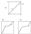
図3(A)はトーンカーブエリア250の詳細を示しており、初期状態でもある。なお、上記のようにヒストグラムも重畳表示するものであるが、以下の説明では理解を容易にするため、各色のヒストグラムについては示しない。
FIG. 3A shows details of the
さて、図3(A)において、251は全色、R、G又はBに対応するトーンカーブであって、初期状態では入力画素値=出力画素値の関係を維持された直線状である。ここで、ユーザは例えばトーンカーブ251上の点Aを入力部101を用いて点A’に移動させることで、図3(B)のように変更することもでき、且つ、図3(B)のB点を点B’に移動させて図3(C)のように変更することもできる。トーンカーブ251を変更を行うと、入出力関係が変るので、図2の画像表示領域202における色調も、これに応じて変化するようにした。トーンカーブの形状変化は、例えば、図3(A)から図3(B)への変化の際には、点Aを点A’に移動させたとき、トーンカーブ251上の点Aに近い部分ほど、移動後の点A’の影響を受けるように補正することで行った。これは点B→B’の変更でも同様である。従って、ユーザはトーンカーブ251の形状を自由に変更することができる。なお、トーンカーブ251をガンマ曲線で表現する場合には、そのガンマ曲線のパラメータのスライダーバーを設けるようにしても構わない。
In FIG. 3A,
次に、明るさスライダーバー260、コントラストスライダーバー270とトーンカーブ251との関係について説明する。
Next, the relationship among the
明るさスライダーバー260は、水平方向に移動可能なツマミ260a(ユーザが移動操作する対象)と、現在のツマミ260の位置に応じた補正量を表示するエリア260bで構成される。ツマミ260aは初期状態で、中央位置にあるので、補正量エリア260bには「0」が表示され、ツマミ260aを右に移動すると、補正量エリア260b内の数値は増加する。逆に、ツマミ260aを左に移動すると、補正量エリア260b内の数値は減少(マイナス)になる。
The
上記動作は、コントラストスライダーバー270についても同様である。つまり、ツマミ270aの位置を変化させると、それに応じた値によって補正量エリア270bの数値が変化する。
The above operation is the same for the
本実施形態では、明るさスライダーバー260やコントラストスライダーバー270を操作すると、それに応じてリアルタイムにトーンカーブ251が変化するものである。以下、その具体例を説明する。
In the present embodiment, when the
なお、以下の説明に先立ち、用語について定義しておくこととする。
(1)出力画素最大値(OUT_MAX):トーンカーブ251で変換された出力画素値の取り得る最大値。
(2)出力画素最小値(OUT_MIN):トーンカーブ251で変換された出力画素値の取り得る最小値。
(3)入力画素ハイライト値(IN_HLT):「出力画素最大値」となる入力画素値の最小値(つまり、これ以上の値を持つ入力画素値はすべて「出力画素最大値」となること意味する)。
(4)入力画素シャドウ値(IN_SDW):「出力画素最小値」となる入力画素値の最大値(つまり、これ以下の値を持つ入力画素値はすべて「出力画素最小値」となること意味する)。
Prior to the following explanation, terms are defined.
(1) Output pixel maximum value (OUT_MAX): The maximum value that the output pixel value converted by the
(2) Output pixel minimum value (OUT_MIN): The minimum value that the output pixel value converted by the
(3) Input pixel highlight value (IN_HLT): The minimum value of the input pixel value that is the “maximum output pixel value” (that is, all input pixel values having a value greater than this are the “maximum output pixel value”) To do).
(4) Input pixel shadow value (IN_SDW): The maximum value of the input pixel value that is the “minimum output pixel value” (that is, all input pixel values having a value less than this value become the “minimum output pixel value”) ).
図4(A)乃至(C)は、明るさスライダーバー260を操作した際のトーンカーブ251の変化を示す図である。図4(A)の場合、出力画素最大値=255、出力画素最小値=0、入力画素ハイライト値=255、入力画素シャドウ値=0の場合でもある。トーンカーブ251はデフォルトのままで直線状態である。
4A to 4C are diagrams showing changes in the
今、明るさスライダーバー260のツマミ260aを右側(+)に移動させると、図4(B)に示すようにトーンカーブ251が上方向に移動する。図4(B)の場合、IN_HLT=I1、IN_SDW=0、OUT_MAX=255、OUT_MIN=O1となる。
Now, when the
一方、図4(C)は明るさを減少させた場合、すなわち、明るさスライダーバー260のツマミ260aを左方向(−方向)に移動させた場合のトーンカーブを示している。図4(C)の場合、IN_HLT=255、IN_SDW=I2、OUT_MAX=O2、OUT_MIN=0となる。
On the other hand, FIG. 4C shows a tone curve when the brightness is reduced, that is, when the
図5(A)乃至(C)はコントラストスライダーバー270を操作した際のトーンカーブ251の変化を示す図である。図5(A)は初期状態である。
5A to 5C are diagrams showing changes in the
今、コントラストスライダーバー270のツマミ270aを右側(+)に移動させると、図5(B)に示すようにトーンカーブ251の傾きが大きくなり、IN_SDW=I3、IN_HLT=I4となる。また、OUT_MAX=255、OUT_MIN=0であり、変化はない。
Now, when the
また、図5(A)の状態で、コントラストスライダーバー270のツマミ270aを左側(−)に移動させると、図5(C)のようにトーンカーブ251の傾きが小さくなる。図5(C)の場合、IN_SDW=0、IN_HLT=255で図5(A)と変らないが、OUT_MAX=O3、OUT_MIN=O4となる。
In addition, when the
上記は、初期状態に対して、明るさスライダーバー260、コントラストスライダーバー270の一方のみを操作した例であった。そこで、両方を操作した場合について説明する。
The above is an example in which only one of the
例えば、図4(B)の状態で、コントラストを上げる操作(コントラストスライダーバー270のツマミ270aを右に移動した場合)に、飽和していない斜線部分の傾きを大きくすることになるから、例えば図6(A)のようになる。
For example, in the state of FIG. 4B, the operation of increasing the contrast (when the
図4(B)での4つのパラメータは、
IN_HLT=I1、IN_SDW=0、OUT_MAX=255、OUT_MIN=O1
であったのに対し、図6(A)では、
IN_HLT=I6、IN_SDW=I5、OUT_MAX=255、OUT_MIN=O1
となる。
The four parameters in FIG.
IN_HLT = I 1 , IN_SDW = 0, OUT_MAX = 255, OUT_MIN = O 1
On the other hand, in FIG.
IN_HLT = I 6 , IN_SDW = I 5 , OUT_MAX = 255, OUT_MIN = O 1
It becomes.
なお、図6(A)は、図5(B)の状態で、明るさを上げるようにした場合でもあるのは、容易に理解できよう。 Note that FIG. 6A can be easily understood that the brightness is increased in the state of FIG. 5B.
また、図4(B)の状態で、コントラストを下げた(コントラストスライダーバー270のツマミ270aを左に移動した場合)には、図6(B)のようになる。
4B, when the contrast is lowered (when the
以上、本実施形態における明るさスライダーバー260、コントラストスライダーバー270の操作によるトーンカーブ251の変化について説明したが、本実施形態におけるトーンカーブによる変換は、次のようにまとめることができる。
The change in the
図7の外枠は、図2におけるトーンカーブエリア250を示している。図示のように、IN_SDW線分(垂直線分)とOUT_MIN線分(水平線分)との交点を点A(x1,y1)と定義し、IN_HLT線分(垂直線分)とOUT_MAX線分(水平線分)との交点を点B(x2、y2)と定義し、入力画素値をDとしたとき、
i. D<IN_SDW(x1)の場合には出力値はy1に固定、
ii. IN_SDW≦D≦IN_HLT(x2)の場合、出力値は点A−Bを結ぶトーンカーブ(の形状)に依存した値、
iii. IN_HLT<Dの場合、出力値はy2に固定、
なお、点A−B間を結ぶトーンカーブは先に説明したように、その形状に変化を持たせることが可能であるが、明るさスライダーバー260、コントラストスライダーバー270を調整することで、その形状が水平或いは垂直軸に沿って伸縮することになる。
The outer frame in FIG. 7 shows the
i. When D <IN_SDW (x1), the output value is fixed at y1.
ii. In the case of IN_SDW ≦ D ≦ IN_HLT (x2), the output value depends on the tone curve (shape) connecting the points AB,
iii. If IN_HLT <D, the output value is fixed at y2.
As described above, the tone curve connecting the points A and B can be changed in its shape, but by adjusting the
<明るさスライダーバーの操作した場合の処理>
明るさスライダーバーの操作した場合の処理を図8(A)及び(B)を用いて説明する。図8(A)及び(B)で説明される処理は、CPU104が画像編集アプリケーションに従って実行する処理である。
<Processing when the brightness slider bar is operated>
Processing when the brightness slider bar is operated will be described with reference to FIGS. The processes described in FIGS. 8A and 8B are processes executed by the
先ず、ステップS301では、明るさスライダーバーが動き、新しい明るさ量Br1が決定する。ステップS302では、図12(A)におけるシャドウIN_SDWと出力画素最小値OUT_MINとの交点Aと、ハイライトIN_HLTと出力画素最大値OUT_MAXとの交点Bを求め、2点A,Bを結ぶ直線Lを求める。 First, in step S301, the brightness slider bar moves to determine a new brightness amount Br1. In step S302, an intersection A between the shadow IN_SDW and the output pixel minimum value OUT_MIN in FIG. 12A and an intersection B between the highlight IN_HLT and the output pixel maximum value OUT_MAX are obtained, and a straight line L connecting the two points A and B is obtained. Ask.
次にステップS303では、直線Lと、x=0との交点である点A1と、直線LとX=255との交点である点B1を求める。ステップS304では、現時点での明るさBr0を求める。トーンカーブでの明るさの定義は、点A1とB1の中点のy座標であるので、そこから、Br0を求めればよい。ステップS305では、Br1と、Br0との差より、明るさの変化量Dを算出する。ステップS306では、点A1と、B1のY座標を、D分移動させた点A2、B2の位置を算出する。ステップS307では、点A2、B2を結ぶ直線L1を算出する(図12(A)参照)。ステップS308では、直線L1とハイライトIN_HLTとの交点を算出し、そのy座標を新しい出力画素最大値Max1とし、OUT_MAXをその位置に更新する。 In step S303, a point A1 that is an intersection of the straight line L and x = 0 and a point B1 that is an intersection of the straight line L and X = 255 are obtained. In step S304, the current brightness Br0 is obtained. Since the definition of the brightness in the tone curve is the y coordinate of the midpoint between the points A1 and B1, Br0 may be obtained therefrom. In step S305, the brightness change amount D is calculated from the difference between Br1 and Br0. In step S306, the positions of points A2 and B2 obtained by moving the Y coordinate of point A1 and B1 by D are calculated. In step S307, a straight line L1 connecting the points A2 and B2 is calculated (see FIG. 12A). In step S308, the intersection of the straight line L1 and the highlight IN_HLT is calculated, the y coordinate is set as the new output pixel maximum value Max1, and OUT_MAX is updated to that position.
ステップS309では、直線L1と、シャドウIN_SDWとの交点を算出し、その交点のy座標を、新しい出力画素最小値Min1とし、その位置にOUT_MINを更新する。 In step S309, the intersection point of the straight line L1 and the shadow IN_SDW is calculated, the y coordinate of the intersection point is set as a new output pixel minimum value Min1, and OUT_MIN is updated at that position.
ステップS310では、図11(B)のように、Max1>255である場合の処理を行う。Max1>255の場合、Max1を“255”に設定し、Max2とする。そして、Max2と、直線L1との交点のX座標を、新しいハイライトH1とし、その位置にハイライトIN_HLTを移動させる。 In step S310, as shown in FIG. 11B, processing when Max1> 255 is performed. When Max1> 255, Max1 is set to “255” and set to Max2. Then, the X coordinate of the intersection of Max2 and the straight line L1 is set as a new highlight H1, and the highlight IN_HLT is moved to that position.
ステップS311では、Min1<0の場合、Min1=0とし、その位置をMin2とする。そして、Min2と直線L1との交点のX座標を、新しいシャドウS1とし、その位置にシャドウIN_SDWを移動させる。 In step S311, if Min1 <0, Min1 = 0 and the position is Min2. Then, the X coordinate of the intersection of Min2 and the straight line L1 is set as a new shadow S1, and the shadow IN_SDW is moved to that position.
ステップS312では、移動後のハイライトIN_HLT、シャドウIN_SDW、出力画素最大値OUT_MAX、出力画素最小値OUT_MINに従ってトーンカーブをリアルタイムに伸縮させる。伸縮は、図14に示したように、曲線の形状を保ったまま、水平、或いは、垂直方向に伸縮されることで行う。さらに、CPU104は、各色のヒストグラムを再計算し、その結果を変更後のトーンカーブとともにリアルタイムにトーンカーブエリア250に表示する。
In step S312, the tone curve is expanded or contracted in real time according to the highlight IN_HLT, shadow IN_SDW, output pixel maximum value OUT_MAX, and output pixel minimum value OUT_MIN after movement. As shown in FIG. 14, the expansion and contraction is performed by expanding and contracting horizontally or vertically while maintaining the shape of the curve. Furthermore, the
<明るさをトーンカーブ上で操作した場合の説明>
上記は、明るさスライダーバー260を左右に移動させることで明るさを変えるものであったが、ハイライトIN_HLT、シャドウIN_SDW、出力画素最大値OUT_MAX、出力画素最小値OUT_MINのいずれか1つの位置を変更した場合に、明るさスライダーバー260に反映させる例を図9を用いて説明する。
<Explanation when brightness is operated on the tone curve>
In the above, the brightness is changed by moving the
4つのパラメータ(ハイライトIN_HLT、シャドウIN_SDW、出力画素最大値OUT_MAX、出力画素最小値OUT_MIN)のそれぞれは、初期状態では、トーンカーブエリア250の外枠の4辺に等しい状態にあり、先に説明した意味を持つ指標軸である。
Each of the four parameters (highlight IN_HLT, shadow IN_SDW, output pixel maximum value OUT_MAX, output pixel minimum value OUT_MIN) is in a state equal to the four sides of the outer frame of the
ユーザは、このトーンカーブエリア250のいずれかの一辺を、入力部101で指定し、ドラッグ操作することで、トーンカーブエリア250の内側の所望とする位置に所望とする指標軸を移動させることができる。ただし、各パラメータは、水平線、垂直線のいずれかであるので、この特性は維持したままの移動となる。例えば、トーンカーブエリア250の右端の垂直線をクリックすると、そこに垂直線ハイライトIN_HLTが移動可能であることを示すハンドラが表示されるので、そのハンドラをドラッグ操作することで、垂直線まま、トーンカーブエリア250内で移動可能となる。そして、必要なら4つのパラメータの線分をすべて移動させることもできる。
The user can move a desired index axis to a desired position inside the
図9で説明される処理は、CPU104が画像編集アプリケーションに従って実行する処理である。
The process illustrated in FIG. 9 is a process executed by the
先ず、ステップS401では、ハイライトIN_HLT、シャドウIN_SDW、出力画素最大値OUT_MAX、出力画素最小値OUT_MINのいずれかが、ユーザによって移動させられる。このとき、点A、Bのいずれかが移動することになるが、その際には点A,B間のトーンカーブも連動して伸縮してリアルタイムに表示更新することになる。さらに、CPU104は、各色のヒストグラムを再計算し、その結果を変更後のトーンカーブとともにリアルタイムにトーンカーブエリア250に表示する。
First, in step S401, one of highlight IN_HLT, shadow IN_SDW, output pixel maximum value OUT_MAX, and output pixel minimum value OUT_MIN is moved by the user. At this time, one of the points A and B moves, and at that time, the tone curve between the points A and B is also expanded and contracted and updated and displayed in real time. Furthermore, the
ステップS402では、図12(A)の点A,Bより、直線Lを算出する。ステップS403では、直線Lと、x=0、x=255との交点である、点A1、B1を求める。次いでステップS404では、点A、B1の中点のy座標より、明るさBrを算出する。 In step S402, a straight line L is calculated from points A and B in FIG. In step S403, points A1 and B1, which are the intersections of the straight line L and x = 0, x = 255, are obtained. Next, in step S404, brightness Br is calculated from the y coordinate of the midpoint of points A and B1.
ステップS405では、求めた明るさBrの値に応じて、明るさスライダーバー260のツマミ260aの位置を変更する。
In step S405, the position of the
以上説明したように、本実施形態によれば、明るさスライダーバー260のツマミ260aを移動させて明るさを調整した場合には、その調整の結果がリアルタイムにトーンカーブに反映されることになり、視覚的に明るさが如何なる状態になったのかを把握できるようになる。また、シャドウIN_SDW、ハイライトIN_HLT、出力画素最大値OUT_MAX、出力画素最小値OUT_MINのいずれかが、ユーザによって移動させた場合にも、それによる明るさ量がスライダーバー260のツマミ位置260aに反映されることになり、ユーザは自身の操作が明るくなるように作用させたのかどうかを簡単にして直感的に把握することができる。
As described above, according to the present embodiment, when the
<コントラストスライダーバーの操作した場合の処理>
次に、本実施形態におけるコントラスト調整とトーンカーブを連動させる例について図10を用いて説明する。
<Processing when the contrast slider bar is operated>
Next, an example of linking the contrast adjustment and the tone curve in this embodiment will be described with reference to FIG.
図10で説明される処理は、CPU104が画像編集アプリケーションに従って実行する処理である。
The process illustrated in FIG. 10 is a process executed by the
先ず、ステップS501では、コントラストスライダーバー270のツマミ270aの操作により、新しいコントラストCt1を決定する。次に、ステップS502では、図13(A)の、シャドウIN_SDWと出力画素最小値OUT_MINとの交点A、ハイライトIN_HLTと出力画素最大値OUT_MAXとの交点Bを求め、点A、B結ぶ直線Lを求める。次に、ステップS503では、直線Lと、X=0との交点である点A1と、直線LとX=255との交点である点B1を求める。ステップS504では、点A1と点B1との中点である点Mを求める。ステップS505では、Ct1より、新しい直線を算出する。コントラスト(Ct)と、直線Lの傾きaとの関係は、
a = tan( Ct*π/2/255);
で与えられる。この式に則り、Ct1より、新しい直線の傾きa1を算出し、点Mを通る直線L1を算出する。ステップS506では、直線L1と出力画素最大値OUT_MAXとの交点を求め、そのx座標を新しいハイライトH1とする。
First, in step S501, a new contrast Ct1 is determined by operating the
a = tan (Ct * π / 2/255);
Given in. In accordance with this equation, a new straight line slope a1 is calculated from Ct1, and a straight line L1 passing through the point M is calculated. In step S506, the intersection of the straight line L1 and the output pixel maximum value OUT_MAX is obtained, and the x coordinate is set as a new highlight H1.
ステップS507では、直線L1と出力画素最小値OUT_MINと交点を求め、そのx座標を新しいシャドウS1とする。 In step S507, the intersection of the straight line L1 and the output pixel minimum value OUT_MIN is obtained, and the x coordinate is set as a new shadow S1.
ステップS508では、図13(B)のように、H1>255の場合、H1=255とし、その位置をH2とする。そして、H2と直線L1との交点のY座標を、新しい画素最大値Max1とする。 In step S508, as shown in FIG. 13B, if H1> 255, H1 = 255 and the position is H2. Then, the Y coordinate of the intersection of H2 and the straight line L1 is set as a new pixel maximum value Max1.
ステップS509では、図13(B)のように、S1<0の場合、S1=0とし、その位置をS2とする。そして、S2と直線L1との交点のY座標を、新しい画素最小値Min1とする。 In step S509, as shown in FIG. 13B, when S1 <0, S1 = 0 and the position is S2. And the Y coordinate of the intersection of S2 and the straight line L1 is made into the new pixel minimum value Min1.
最後に、ステップS510において、移動後のハイライトIN_HLT、シャドウIN_SDW、出力画素最大値OUT_MAX、出力画素最小値OUT_MINに従ってトーンカーブをリアルタイムに伸縮させる。さらに、CPU104は、各色のヒストグラムを再計算し、その結果を変更後のトーンカーブとともにリアルタイムにトーンカーブエリア250に表示する。
Finally, in step S510, the tone curve is expanded or contracted in real time according to the highlight IN_HLT, shadow IN_SDW, output pixel maximum value OUT_MAX, and output pixel minimum value OUT_MIN after movement. Furthermore, the
<コントラストをトーンカーブ上で操作した場合の説明>
コントラストを調整するのは、上記のコントラストスライドバー270だけでなく、4つのパラメータ{ハイライトIN_HLT、シャドウIN_SDW、出力画素最大値OUT_MAX、出力画素最小値OUT_MIN}のいずれか1つを移動させた場合にも可能である。この処理を図11を用いて説明する。図11で説明される処理は、CPU104が画像編集アプリケーションに従って実行する処理である。
<Explanation when contrast is operated on tone curve>
The contrast is adjusted when not only the above
先ず、ステップS601で、シャドウIN_SDW、ハイライトIN_HLT、出力画素最大値OUT_MAX、出力画素最小値OUT_MINのいずれか1つがユーザによって移動させる。この結果、点A,Bのいずれか一方も移動することになるので、トーンカーブもそれに応じて伸縮表示更新することになる。さらに、CPU104は、各色のヒストグラムを再計算し、その結果を変更後のトーンカーブとともにリアルタイムにトーンカーブエリア250に表示する。
First, in step S601, one of shadow IN_SDW, highlight IN_HLT, output pixel maximum value OUT_MAX, and output pixel minimum value OUT_MIN is moved by the user. As a result, either one of the points A and B moves, so that the tone curve is also updated in accordance with the expansion / contraction display. Furthermore, the
ステップS602では、図12(A)のトーンカーブ701での点A、Bより、直線Lを算出する。ステップS603では、直線Lと、X=0、X=255との交点であるA1、B1を求める。 In step S602, a straight line L is calculated from points A and B on the tone curve 701 in FIG. In step S603, A1 and B1 which are intersections of the straight line L and X = 0 and X = 255 are obtained.
ステップS604では、点A、B1を結ぶ直線の傾きから、新しいコントラストCtを算出する。コントラスト算出では、以下の式を用いる。このとき、A1の座標を(X1, Y1)、B1の座標を(X2, Y2)とする。
Ct = atan( (Y2-Y1)/(X2-X1)/(π/2)*255 );
ステップS605では、求めたコントラストCtの値に従い、コントラストスライダーバー270のツマミ270aの位置に変更し、表示更新する。
In step S604, a new contrast Ct is calculated from the slope of the straight line connecting the points A and B1. In the contrast calculation, the following formula is used. At this time, the coordinates of A1 are (X1, Y1), and the coordinates of B1 are (X2, Y2).
Ct = atan ((Y2-Y1) / (X2-X1) / (π / 2) * 255);
In step S605, the position is changed to the position of the
以上のように、コントラストスライダーバー270によってトーンカーブを変更した場合には、ユーザはそのツマミ270aの位置でもってコントラストをどの程度変更したのかを把握できると共に、トーンカーブのシャドウIN_SDW、ハイライトIN_HLT、出力画素最大値OUT_MAX、出力画素最小値OUT_MINのいずれかの移動によっても、ツマミ270aの位置にそれが反映されることになり、コントラストを一意に設定できるようになり、ユーザインタフェース上でのまぎらわしさを軽減できるようになる。
As described above, when the tone curve is changed by the
なお、明るさ及びコントラストの調整は、図2における色成分選択エリア240で選択した色成分についてのみなされる。また、トーンカーブ上でハイライトIN_HLT、シャドウIN_SDW、出力画素最大値OUT_MAX、出力画素最小値OUT_MINのいずれかの位置を変更した場合、その結果は明るさ及びコントラストの両方に影響を与えることも当然に有り得る。従って、実際には図9の処理を終えたら図11の処理に進むものである(順序は逆でも構わない)。
The brightness and contrast are adjusted only for the color component selected in the color
<メイン処理の説明>
次に、本実施形態におけるCPU104が画像編集アプリケーションに従って実行するメイン処理を図16のフローチャートに従って説明する。
<Description of main processing>
Next, main processing executed by the
先ず、ステップS1にて、編集したい画像ファイルを選択する。この選択は、図2のGUIウインドウ200内のエリア201にパス付きのファイル名を入力することで行う。例えば、ファイル一覧を表示してその中から入力部101で指定することで行う。画像ファイルの選択が行われると、ステップS2に進み、トーンカーブを初期化する。この初期化では、入力画素値=出力画素値(すなわち、x、y座標系でいうと「y=x」なる傾き「1」の線形)に設定する。
First, in step S1, an image file to be edited is selected. This selection is performed by inputting a file name with a path in the
次に、ステップS3に進み、現在のトーンカーブに従って画像ファイルの画像データを変換する。変換結果はRAM106に格納するものとする。初期化直後のトーンカーブは、「入力画素値=出力画素値」の関係にあるので、結局のところ、選択した画像ファイルに対して何も変換していないことと等価のものとなる。変換結果の画像は、図2の画像表示領域202に表示される(原画像に比べて小さいので間引き表示する)。
In step S3, the image data of the image file is converted according to the current tone curve. The conversion result is stored in the
次に、ステップS4に進み、変換後の画像データのヒストグラムを生成し、トーンカーブエリア250に表示する。本実施形態で表示するヒストグラムはRGBの各色成分についてのものであるので、それぞれの色のヒストグラムを表示する。画像ファイルを選択し、トーンカーブの初期化直後のトーンカーブエリア250の状態を示すのが図15(A)である。なお、ヒストグラムを作成する処理は、単純である。一次元変数Red()、Green()、Blue()を用意し、入力した画素のR、G、Bの成分をPr,Pg,Pb(いずれも整数)としたとき、
Red(Pr)←Red(Pr)+1
Green(Pg)←Green(Pg)+1
Blue(Pb)←Blue(Pb)+1
として、全画素について求めていけばよい。
In
Red (Pr) ← Red (Pr) +1
Green (Pg) ← Green (Pg) +1
Blue (Pb) ← Blue (Pb) +1
As for all pixels.
次に、ステップS5に進み、ユーザによる指示入力を待ち、その指示入力をステップS6、8、9にて判定することになる。 Next, the process proceeds to step S5, waiting for an instruction input by the user, and the instruction input is determined in steps S6, S8 and S9.
先ず、トーンカーブの形状変更指示、明るさスライダーバー260やコントラストスライダーバー270の操作、或いは、トーンカーブエリア250におけるハイライトIN_HLT、シャドウIN_SDW、出力画素最大値OUT_MAX、出力画素最小値OUT_MINの移動操作であると判断した場合、ステップS6からステップS7に進み、先に説明したトーンカーブの変更処理を行う。トーンカーブの変更処理が行われると、変更後のトーンカーブに従って画像変換を行うべくステップS3に戻ることになる。この結果、ヒストグラムが再度生成され、更新されることになる。図12(B)は、明るさを上げた操作をした場合におけるトーンカーブエリアの表示状態を示している。図12(B)に示す如く、本実施形態の画像編集アプリケーションによれば、トーンカーブをリアルタイムに変更することができ、その結果に基づく各色のヒストグラムの変化をリアルタイムに知ることができる。
First, the tone curve shape change instruction, the operation of the
以上、ステップS3乃至S7を繰り返すことで、ユーザは、意図したトーンカーブを決定することになる。 As described above, by repeating steps S3 to S7, the user determines the intended tone curve.
さて、ステップS5にて入力された操作がOKボタン203であると判定した場合には、その時点で変換されていた画像を保存する。保存する際には、オリジナル画像ファイルに上書きするものとするが、名前を変えて保存しても構わない。また、キャンセルボタン204が押下された場合には本処理を終了することになる。
If it is determined in step S5 that the input operation is the
以上説明したように本実施形態によれば、画像のトーンカーブを調整するためのGUIウインドウにおいて、スライダーバーによる調整結果がリアルタイムにトーンカーブに反映することにより、ユーザの操作とトーンカーブとの関係が一目瞭然とさせることができる。また、ハイライトIN_HLT、シャドウIN_SDW、出力画素最大値OUT_MAX、出力画素最小値OUT_MINの1つを移動させる操作を行った場合にも、その結果が、明るさ及びコントラストスライダーバーに反映されることになるので、明るさ及びコントラストに対してどのような操作を行ったのかも容易に理解しつつ操作することが可能となる。また、トーンカーブの調整を行えば、各色のヒストグラムもそれに応じてリアルタイムに変化するので、画像データの変換結果を客観的に評価することも可能となる。更にまた、トーンカーブの変化と各色のヒストグラムの変化とを視点を変えずに知ることもできる優れたユーザインタフェースを提供することが可能となる。 As described above, according to the present embodiment, in the GUI window for adjusting the tone curve of the image, the adjustment result by the slider bar is reflected in the tone curve in real time, so that the relationship between the user operation and the tone curve is achieved. Can be seen at a glance. In addition, when an operation of moving one of highlight IN_HLT, shadow IN_SDW, output pixel maximum value OUT_MAX, and output pixel minimum value OUT_MIN is performed, the result is reflected in the brightness and contrast slider bar. Therefore, it is possible to operate while easily understanding what operation is performed on the brightness and contrast. Further, if the tone curve is adjusted, the histogram of each color also changes in real time accordingly, so that the conversion result of the image data can be objectively evaluated. Furthermore, it is possible to provide an excellent user interface that can know the change of the tone curve and the change of the histogram of each color without changing the viewpoint.
なお、本実施形態から明らかなように、本発明は、パーソナルコンピュータ等の汎用コンピュータ上で実行するコンピュータプログラムに適用されるものである。また、通常、コンピュータプログラムはCD−ROM等のコンピュータ可読記憶媒体に格納されている。そして、その媒体をコンピュータが有するドライブにセットしてシステムにコピーもしくはインストールされて実行可能となるわけであるから、当然、本発明はかかるコンピュータ可読記憶媒体をもその範疇とする。 As is clear from this embodiment, the present invention is applied to a computer program executed on a general-purpose computer such as a personal computer. In general, the computer program is stored in a computer-readable storage medium such as a CD-ROM. Since the medium can be set in a drive of the computer and copied or installed in the system and executed, the present invention naturally includes such a computer-readable storage medium.
また、本実施形態で説明したGUIは、本発明の一つの例であって、上記実施形態のみによって本発明が限定されるものでもない。 The GUI described in the present embodiment is an example of the present invention, and the present invention is not limited only by the above-described embodiment.
Claims (19)
前記第2の表示エリアに設けられたスライダーバーを用いて前記変換カーブを調整し、表示された変換カーブを更新する第1の調整手段と、
前記第1の表示エリア内にて、出力画素値の上限を既定する出力画素最大値の軸、出力画素値の下限を既定する出力画素最小値の軸、入力画素値がそれ以上である場合に前記出力画素最大値にするハイライト軸、入力画素値がそれ以下の場合に前記出力画素最小値にするシャドウ軸のうち少なくとも1つの位置を変更することで前記変換カーブを調整し、表示された変換カーブを更新する第2の調整手段と、
前記第2の調整手段で前記変換カーブを調整した場合、調整後の変換カーブに基づいて前記スライダーバーの状態を更新する更新手段と
を備えることを特徴とする画像処理装置。 A conversion curve indicating the relationship of the output pixel value to the input pixel value is displayed in the first display area, and a slider bar for adjusting the brightness is displayed in the second display area provided outside the first display area. Display means for displaying;
First adjustment means for adjusting the conversion curve using a slider bar provided in the second display area and updating the displayed conversion curve;
In the first display area, an output pixel maximum value axis defining the upper limit of the output pixel value, an output pixel minimum value axis defining the lower limit of the output pixel value, and an input pixel value greater than that The conversion curve is adjusted by changing the position of at least one of the highlight axis that makes the output pixel maximum value and the shadow axis that makes the output pixel minimum value when the input pixel value is less than that, and is displayed A second adjusting means for updating the conversion curve;
An image processing apparatus comprising: an updating unit that updates the state of the slider bar based on the converted conversion curve when the conversion curve is adjusted by the second adjusting unit.
前記第2の表示エリアに設けられたスライダーバーを用いて前記変換カーブを調整し、表示された変換カーブを更新する第1の調整手段と、
前記第1の表示エリア内にて、出力画素値の上限を既定する出力画素最大値の軸、出力画素値の下限を既定する出力画素最小値の軸、入力画素値がそれ以上である場合に前記出力画素最大値にするハイライト軸、入力画素値がそれ以下の場合に前記出力画素最小値にするシャドウ軸のうち少なくとも1つの位置を変更することで前記変換カーブを調整し、表示された変換カーブを更新する第2の調整手段と、
前記第2の調整手段で前記変換カーブを調整した場合、調整後の変換カーブに基づいて前記スライダーバーの状態を更新する更新手段と
を備えることを特徴とする画像処理装置。 A conversion curve indicating the relationship of the output pixel value to the input pixel value is displayed in the first display area, and a slider bar for adjusting the contrast is displayed in the second display area provided outside the first display area. Display means to
First adjustment means for adjusting the conversion curve using a slider bar provided in the second display area and updating the displayed conversion curve;
In the first display area, an output pixel maximum value axis defining the upper limit of the output pixel value, an output pixel minimum value axis defining the lower limit of the output pixel value, and an input pixel value greater than that The conversion curve is adjusted by changing the position of at least one of the highlight axis that makes the output pixel maximum value and the shadow axis that makes the output pixel minimum value when the input pixel value is less than that, and is displayed A second adjusting means for updating the conversion curve;
Updating means for updating the state of the slider bar based on the converted conversion curve when the conversion curve is adjusted by the second adjusting means;
An image processing apparatus comprising:
前記第2の表示エリアに設けられた前記明るさスライダーバー及び前記コントラストスライダーバーを用いて前記変換カーブを調整し、表示された変換カーブを更新する第1の調整手段と、
前記第1の表示エリア内にて、出力画素値の上限を既定する出力画素最大値の軸、出力画素値の下限を既定する出力画素最小値の軸、入力画素値がそれ以上である場合に前記出力画素最大値にするハイライト軸、入力画素値がそれ以下の場合に前記出力画素最小値にするシャドウ軸のうち少なくとも1つの位置を変更することで前記変換カーブを調整し、表示された変換カーブを更新する第2の調整手段と、
前記第2の調整手段で前記変換カーブを調整した場合、調整後の変換カーブに基づいて前記明るさスライダーバー及び前記コントラストスライダーバーの状態を更新する更新手段と
を備えることを特徴とする画像処理装置。 A conversion curve indicating the relationship between the input pixel value and the output pixel value is displayed in the first display area, and a brightness slider bar for adjusting brightness and a contrast slider bar for adjusting contrast are displayed in the first display area. Display means for displaying in a second display area provided outside the area;
First adjusting means for adjusting the conversion curve using the brightness slider bar and the contrast slider bar provided in the second display area, and updating the displayed conversion curve;
In the first display area, an output pixel maximum value axis defining the upper limit of the output pixel value, an output pixel minimum value axis defining the lower limit of the output pixel value, and an input pixel value greater than that The conversion curve is adjusted by changing the position of at least one of the highlight axis that makes the output pixel maximum value and the shadow axis that makes the output pixel minimum value when the input pixel value is less than that, and is displayed A second adjusting means for updating the conversion curve;
Updating means for updating states of the brightness slider bar and the contrast slider bar based on the adjusted conversion curve when the conversion curve is adjusted by the second adjustment means;
An image processing apparatus comprising:
前記第2の表示エリアに設けられたスライダーバーを用いて前記変換カーブを調整し、表示された変換カーブを更新する第1の調整工程と、
前記第1の表示エリア内にて、出力画素値の上限を既定する出力画素最大値の軸、出力画素値の下限を既定する出力画素最小値の軸、入力画素値がそれ以上である場合に前記出力画素最大値にするハイライト軸、入力画素値がそれ以下の場合に前記出力画素最小値にするシャドウ軸のうち少なくとも1つの位置を変更することで前記変換カーブを調整し、表示された変換カーブを更新する第2の調整工程と、
前記第2の調整工程で前記変換カーブを調整した場合、調整後の変換カーブに基づいて前記スライダーバーの状態を更新する更新工程と
を備えることを特徴とする画像処理方法。 A conversion curve indicating the relationship of the output pixel value to the input pixel value is displayed in the first display area, and a slider bar for adjusting the brightness is displayed in the second display area provided outside the first display area. A display process to display;
A first adjustment step of adjusting the conversion curve using a slider bar provided in the second display area and updating the displayed conversion curve;
In the first display area, an output pixel maximum value axis defining the upper limit of the output pixel value, an output pixel minimum value axis defining the lower limit of the output pixel value, and an input pixel value greater than that The conversion curve is adjusted by changing the position of at least one of the highlight axis that makes the output pixel maximum value and the shadow axis that makes the output pixel minimum value when the input pixel value is less than that, and is displayed A second adjustment step for updating the conversion curve;
An image processing method comprising: an update step of updating the state of the slider bar based on the adjusted conversion curve when the conversion curve is adjusted in the second adjustment step.
前記第2の表示エリアに設けられたスライダーバーを用いて前記変換カーブを調整し、表示された変換カーブを更新する第1の調整工程と、A first adjustment step of adjusting the conversion curve using a slider bar provided in the second display area and updating the displayed conversion curve;
前記第1の表示エリア内にて、出力画素値の上限を既定する出力画素最大値の軸、出力画素値の下限を既定する出力画素最小値の軸、入力画素値がそれ以上である場合に前記出力画素最大値にするハイライト軸、入力画素値がそれ以下の場合に前記出力画素最小値にするシャドウ軸のうち少なくとも1つの位置を変更することで前記変換カーブを調整し、表示された変換カーブを更新する第2の調整工程と、In the first display area, an output pixel maximum value axis defining the upper limit of the output pixel value, an output pixel minimum value axis defining the lower limit of the output pixel value, and an input pixel value greater than that The conversion curve is adjusted by changing the position of at least one of the highlight axis that makes the output pixel maximum value and the shadow axis that makes the output pixel minimum value when the input pixel value is less than that, and is displayed A second adjustment step for updating the conversion curve;
前記第2の調整工程で前記変換カーブを調整した場合、調整後の変換カーブに基づいて前記スライダーバーの状態を更新する更新工程とAn update step of updating the state of the slider bar based on the adjusted conversion curve when the conversion curve is adjusted in the second adjustment step;
を備えることを特徴とする画像処理方法。An image processing method comprising:
前記第2の表示エリアに設けられた前記明るさスライダーバー及び前記コントラストスライダーバーを用いて前記変換カーブを調整し、表示された変換カーブを更新する第1の調整工程と、A first adjustment step of adjusting the conversion curve using the brightness slider bar and the contrast slider bar provided in the second display area, and updating the displayed conversion curve;
前記第1の表示エリア内にて、出力画素値の上限を既定する出力画素最大値の軸、出力画素値の下限を既定する出力画素最小値の軸、入力画素値がそれ以上である場合に前記出力画素最大値にするハイライト軸、入力画素値がそれ以下の場合に前記出力画素最小値にするシャドウ軸のうち少なくとも1つの位置を変更することで前記変換カーブを調整し、表示された変換カーブを更新する第2の調整工程と、In the first display area, an output pixel maximum value axis defining the upper limit of the output pixel value, an output pixel minimum value axis defining the lower limit of the output pixel value, and an input pixel value greater than that The conversion curve is adjusted by changing the position of at least one of the highlight axis that makes the output pixel maximum value and the shadow axis that makes the output pixel minimum value when the input pixel value is less than that, and is displayed A second adjustment step for updating the conversion curve;
前記第2の調整工程で前記変換カーブを調整した場合、調整後の変換カーブに基づいて前記明るさスライダーバー及び前記コントラストスライダーバーの状態を更新する更新工程とAn update step of updating the states of the brightness slider bar and the contrast slider bar based on the adjusted conversion curve when the conversion curve is adjusted in the second adjustment step;
を備えることを特徴とする画像処理方法。An image processing method comprising:
入力画素値に対する出力画素値の関係を示す変換カーブを第1の表示エリアに表示し、明るさを調整するためのスライダーバーを前記第1の表示エリア外に設けられた第2の表示エリアに表示する表示手段と、
前記第2の表示エリアに設けられたスライダーバーを用いて前記変換カーブを調整し、表示された変換カーブを更新する第1の調整手段と、
前記第1の表示エリア内にて、出力画素値の上限を既定する出力画素最大値の軸、出力画素値の下限を既定する出力画素最小値の軸、入力画素値がそれ以上である場合に前記出力画素最大値にするハイライト軸、入力画素値がそれ以下の場合に前記出力画素最小値にするシャドウ軸のうち少なくとも1つの位置を変更することで前記変換カーブを調整し、表示された変換カーブを更新する第2の調整手段と、
前記第2の調整手段で前記変換カーブを調整した場合、調整後の変換カーブに基づいて前記スライダーバーの状態を更新する更新手段と
として機能させることを特徴とするコンピュータプログラム。 A computer program for causing a computer to function as an image processing apparatus by being read and executed by a computer,
A conversion curve indicating the relationship of the output pixel value to the input pixel value is displayed in the first display area, and a slider bar for adjusting the brightness is displayed in the second display area provided outside the first display area. Display means for displaying;
First adjustment means for adjusting the conversion curve using a slider bar provided in the second display area and updating the displayed conversion curve;
In the first display area, an output pixel maximum value axis defining the upper limit of the output pixel value, an output pixel minimum value axis defining the lower limit of the output pixel value, and an input pixel value greater than that The conversion curve is adjusted by changing the position of at least one of the highlight axis that makes the output pixel maximum value and the shadow axis that makes the output pixel minimum value when the input pixel value is less than that, and is displayed A second adjusting means for updating the conversion curve;
When the conversion curve is adjusted by the second adjustment means, the computer program is made to function as update means for updating the state of the slider bar based on the adjusted conversion curve.
入力画素値に対する出力画素値の関係を示す変換カーブを第1の表示エリアに表示し、コントラストを調整するためのスライダーバーを前記第1の表示エリア外に設けられた第2の表示エリアに表示する表示手段と、A conversion curve indicating the relationship of the output pixel value to the input pixel value is displayed in the first display area, and a slider bar for adjusting the contrast is displayed in the second display area provided outside the first display area. Display means to
前記第2の表示エリアに設けられたスライダーバーを用いて前記変換カーブを調整し、表示された変換カーブを更新する第1の調整手段と、First adjustment means for adjusting the conversion curve using a slider bar provided in the second display area and updating the displayed conversion curve;
前記第1の表示エリア内にて、出力画素値の上限を既定する出力画素最大値の軸、出力画素値の下限を既定する出力画素最小値の軸、入力画素値がそれ以上である場合に前記出力画素最大値にするハイライト軸、入力画素値がそれ以下の場合に前記出力画素最小値にするシャドウ軸のうち少なくとも1つの位置を変更することで前記変換カーブを調整し、表示された変換カーブを更新する第2の調整手段と、In the first display area, an output pixel maximum value axis defining the upper limit of the output pixel value, an output pixel minimum value axis defining the lower limit of the output pixel value, and an input pixel value greater than that The conversion curve is adjusted by changing the position of at least one of the highlight axis that makes the output pixel maximum value and the shadow axis that makes the output pixel minimum value when the input pixel value is less than that, and is displayed A second adjusting means for updating the conversion curve;
前記第2の調整手段で前記変換カーブを調整した場合、調整後の変換カーブに基づいて前記スライダーバーの状態を更新する更新手段とUpdating means for updating the state of the slider bar based on the converted conversion curve when the conversion curve is adjusted by the second adjusting means;
として機能させることを特徴とするコンピュータプログラム。A computer program that functions as a computer program.
入力画素値に対する出力画素値の関係を示す変換カーブを第1の表示エリアに表示し、明るさを調整するための明るさスライダーバー及びコントラストを調整するためのコントラストスライダーバーを前記第1の表示エリア外に設けられた第2の表示エリアに表示する表示手段と、A conversion curve indicating the relationship between the input pixel value and the output pixel value is displayed in the first display area, and a brightness slider bar for adjusting brightness and a contrast slider bar for adjusting contrast are displayed in the first display area. Display means for displaying in a second display area provided outside the area;
前記第2の表示エリアに設けられた前記明るさスライダーバー及び前記コントラストスライダーバーを用いて前記変換カーブを調整し、表示された変換カーブを更新する第1の調整手段と、First adjusting means for adjusting the conversion curve using the brightness slider bar and the contrast slider bar provided in the second display area, and updating the displayed conversion curve;
前記第1の表示エリア内にて、出力画素値の上限を既定する出力画素最大値の軸、出力画素値の下限を既定する出力画素最小値の軸、入力画素値がそれ以上である場合に前記出力画素最大値にするハイライト軸、入力画素値がそれ以下の場合に前記出力画素最小値にするシャドウ軸のうち少なくとも1つの位置を変更することで前記変換カーブを調整し、表示された変換カーブを更新する第2の調整手段と、In the first display area, an output pixel maximum value axis defining the upper limit of the output pixel value, an output pixel minimum value axis defining the lower limit of the output pixel value, and an input pixel value greater than that The conversion curve is adjusted by changing the position of at least one of the highlight axis that makes the output pixel maximum value and the shadow axis that makes the output pixel minimum value when the input pixel value is less than that, and is displayed A second adjusting means for updating the conversion curve;
前記第2の調整手段で前記変換カーブを調整した場合、調整後の変換カーブに基づいて前記明るさスライダーバー及び前記コントラストスライダーバーの状態を更新する更新手段とUpdating means for updating states of the brightness slider bar and the contrast slider bar based on the adjusted conversion curve when the conversion curve is adjusted by the second adjustment means;
として機能させることを特徴とするコンピュータプログラム。A computer program that functions as a computer program.
Priority Applications (2)
| Application Number | Priority Date | Filing Date | Title |
|---|---|---|---|
| JP2004020386A JP4143549B2 (en) | 2004-01-28 | 2004-01-28 | Image processing apparatus and method, computer program, and computer-readable storage medium |
| US11/044,701 US20050163368A1 (en) | 2004-01-28 | 2005-01-27 | Image processing apparatus and method therefor |
Applications Claiming Priority (1)
| Application Number | Priority Date | Filing Date | Title |
|---|---|---|---|
| JP2004020386A JP4143549B2 (en) | 2004-01-28 | 2004-01-28 | Image processing apparatus and method, computer program, and computer-readable storage medium |
Publications (3)
| Publication Number | Publication Date |
|---|---|
| JP2005217655A JP2005217655A (en) | 2005-08-11 |
| JP2005217655A5 JP2005217655A5 (en) | 2007-03-15 |
| JP4143549B2 true JP4143549B2 (en) | 2008-09-03 |
Family
ID=34792607
Family Applications (1)
| Application Number | Title | Priority Date | Filing Date |
|---|---|---|---|
| JP2004020386A Expired - Fee Related JP4143549B2 (en) | 2004-01-28 | 2004-01-28 | Image processing apparatus and method, computer program, and computer-readable storage medium |
Country Status (2)
| Country | Link |
|---|---|
| US (1) | US20050163368A1 (en) |
| JP (1) | JP4143549B2 (en) |
Families Citing this family (13)
| Publication number | Priority date | Publication date | Assignee | Title |
|---|---|---|---|---|
| TWI283396B (en) * | 2004-03-23 | 2007-07-01 | Lite On Technology Corp | Method for adjusting image contrast |
| US7286131B2 (en) * | 2005-05-26 | 2007-10-23 | Microsoft Corporation | Generating an approximation of an arbitrary curve |
| JP4665775B2 (en) * | 2006-01-24 | 2011-04-06 | 富士ゼロックス株式会社 | User interface device and control method thereof |
| JP4325627B2 (en) | 2006-02-21 | 2009-09-02 | ソニー株式会社 | Image display method, image display apparatus, and imaging apparatus |
| US8487931B2 (en) * | 2006-09-07 | 2013-07-16 | Adobe Systems Incorporated | Dynamic feedback and interaction for parametric curves |
| JP4780129B2 (en) * | 2008-03-21 | 2011-09-28 | ブラザー工業株式会社 | Image processing method and image processing apparatus |
| JP5697570B2 (en) * | 2011-09-29 | 2015-04-08 | 京セラドキュメントソリューションズ株式会社 | Image forming apparatus |
| JP6244654B2 (en) * | 2013-05-14 | 2017-12-13 | 船井電機株式会社 | Image display device |
| CN104184974B (en) * | 2014-09-03 | 2018-02-09 | 北京时代奥视科技股份有限公司 | The screening technique and device of video luminance signal display methods and anomalous video signal |
| WO2017219962A1 (en) * | 2016-06-21 | 2017-12-28 | Zhejiang Dahua Technology Co., Ltd. | Systems and methods for image processing |
| US10346020B2 (en) * | 2016-10-20 | 2019-07-09 | Adobe Inc. | Relatively changing a parametric value using a pressure sensitive user interface element |
| JP7403279B2 (en) * | 2019-10-31 | 2023-12-22 | キヤノン株式会社 | Image processing device and image processing method |
| US11783453B2 (en) * | 2021-06-10 | 2023-10-10 | Bank Of America Corporation | Adapting image noise removal model based on device capabilities |
Family Cites Families (8)
| Publication number | Priority date | Publication date | Assignee | Title |
|---|---|---|---|---|
| JPH0997319A (en) * | 1995-09-28 | 1997-04-08 | Fujitsu Ltd | Processor for correcting color space image and method therefor |
| US5982379A (en) * | 1996-06-04 | 1999-11-09 | Ricoh Company, Ltd. | Interactive color system editor and method of specifying potable color system framework representation |
| US5874988A (en) * | 1996-07-08 | 1999-02-23 | Da Vinci Systems, Inc. | System and methods for automated color correction |
| EP1489833A1 (en) * | 1997-06-17 | 2004-12-22 | Seiko Epson Corporation | Image processing apparatus, image processing method, color adjustment method, and color adjustment system |
| US7039876B2 (en) * | 1997-10-06 | 2006-05-02 | Canon Kabushiki Kaisha | User interface for image acquisition devices |
| JP2001209785A (en) * | 1999-11-19 | 2001-08-03 | Fujitsu Ltd | Device and method for image processing and image processing program storage medium |
| US7006688B2 (en) * | 2001-07-05 | 2006-02-28 | Corel Corporation | Histogram adjustment features for use in imaging technologies |
| KR100490405B1 (en) * | 2002-07-02 | 2005-05-17 | 삼성전자주식회사 | Method for adjusting image color in printing system and graphical user interface therefor |
-
2004
- 2004-01-28 JP JP2004020386A patent/JP4143549B2/en not_active Expired - Fee Related
-
2005
- 2005-01-27 US US11/044,701 patent/US20050163368A1/en not_active Abandoned
Also Published As
| Publication number | Publication date |
|---|---|
| JP2005217655A (en) | 2005-08-11 |
| US20050163368A1 (en) | 2005-07-28 |
Similar Documents
| Publication | Publication Date | Title |
|---|---|---|
| US8310720B2 (en) | Color adjustment apparatus, image forming apparatus, and computer-readable recording medium | |
| US20050163368A1 (en) | Image processing apparatus and method therefor | |
| JP4677323B2 (en) | Image processing apparatus and image processing method | |
| US7697161B2 (en) | Method of displaying wallpaper and apparatus for displaying wallpaper | |
| JP5006757B2 (en) | Image processing apparatus and image processing method | |
| JP2000261649A (en) | Image processing method, device thereof and storage medium | |
| PT947955E (en) | APPARATUS FOR GENERATING RANGE CURVES ADAPTED TO A DETAILED APPLICATION FOR COLOR CORRECTION EQUIPMENT | |
| WO2005104041A1 (en) | Image plotting device and method thereof | |
| JP2007228189A (en) | Color table editing apparatus, color table editing method, program and storage medium | |
| KR20110075179A (en) | Correction method of image color using multi-touchable touch screen | |
| JP2008110008A (en) | Embroidery data creating device, embroidery data creating program, and recording medium recorded with the embroidery data creating program | |
| KR20030088862A (en) | Apparatus for producing sewing data and program for producing sewing data | |
| JP7114049B2 (en) | Image processing device and image processing program | |
| JP2008219422A (en) | Apparatus and method for processing information | |
| CN108255450B (en) | Method and system for WORD document display control of spliced wall | |
| KR101145602B1 (en) | Correction method of image color using multi-touchable touch screen | |
| JP7330734B2 (en) | Image processing device and its control method and program | |
| JPH0785099A (en) | System for displaying hierarchy | |
| JP2006121421A (en) | Device and method for color converging image data and recording medium recording its program | |
| JP2009253474A (en) | Image processing device, image processing method, and image processing program | |
| JP2009032121A (en) | Color generation support device and color generation support program | |
| JP3848000B2 (en) | Image processing apparatus, image processing method, and storage medium | |
| JP2005084089A (en) | Image comparison display method and its device, and image comparison display program | |
| JP4802981B2 (en) | Color conversion table creation program, color conversion table creation device, and color conversion table creation system | |
| JP2008118355A (en) | Image processor and image processing method |
Legal Events
| Date | Code | Title | Description |
|---|---|---|---|
| A521 | Request for written amendment filed |
Free format text: JAPANESE INTERMEDIATE CODE: A523 Effective date: 20070129 |
|
| A621 | Written request for application examination |
Free format text: JAPANESE INTERMEDIATE CODE: A621 Effective date: 20070129 |
|
| A977 | Report on retrieval |
Free format text: JAPANESE INTERMEDIATE CODE: A971007 Effective date: 20080305 |
|
| A131 | Notification of reasons for refusal |
Free format text: JAPANESE INTERMEDIATE CODE: A131 Effective date: 20080314 |
|
| A521 | Request for written amendment filed |
Free format text: JAPANESE INTERMEDIATE CODE: A523 Effective date: 20080509 |
|
| TRDD | Decision of grant or rejection written | ||
| A01 | Written decision to grant a patent or to grant a registration (utility model) |
Free format text: JAPANESE INTERMEDIATE CODE: A01 Effective date: 20080606 |
|
| A01 | Written decision to grant a patent or to grant a registration (utility model) |
Free format text: JAPANESE INTERMEDIATE CODE: A01 |
|
| A61 | First payment of annual fees (during grant procedure) |
Free format text: JAPANESE INTERMEDIATE CODE: A61 Effective date: 20080616 |
|
| FPAY | Renewal fee payment (event date is renewal date of database) |
Free format text: PAYMENT UNTIL: 20110620 Year of fee payment: 3 |
|
| R150 | Certificate of patent or registration of utility model |
Ref document number: 4143549 Country of ref document: JP Free format text: JAPANESE INTERMEDIATE CODE: R150 Free format text: JAPANESE INTERMEDIATE CODE: R150 |
|
| FPAY | Renewal fee payment (event date is renewal date of database) |
Free format text: PAYMENT UNTIL: 20120620 Year of fee payment: 4 |
|
| FPAY | Renewal fee payment (event date is renewal date of database) |
Free format text: PAYMENT UNTIL: 20120620 Year of fee payment: 4 |
|
| FPAY | Renewal fee payment (event date is renewal date of database) |
Free format text: PAYMENT UNTIL: 20130620 Year of fee payment: 5 |
|
| LAPS | Cancellation because of no payment of annual fees |