JP4143103B2 - MOBILE DEVICE, ITS CONTROL SYSTEM, CONTROL PROGRAM, AND SUPERVISION SYSTEM - Google Patents
MOBILE DEVICE, ITS CONTROL SYSTEM, CONTROL PROGRAM, AND SUPERVISION SYSTEM Download PDFInfo
- Publication number
- JP4143103B2 JP4143103B2 JP2006342638A JP2006342638A JP4143103B2 JP 4143103 B2 JP4143103 B2 JP 4143103B2 JP 2006342638 A JP2006342638 A JP 2006342638A JP 2006342638 A JP2006342638 A JP 2006342638A JP 4143103 B2 JP4143103 B2 JP 4143103B2
- Authority
- JP
- Japan
- Prior art keywords
- processing unit
- spatial
- action plan
- contact condition
- determination
- Prior art date
- Legal status (The legal status is an assumption and is not a legal conclusion. Google has not performed a legal analysis and makes no representation as to the accuracy of the status listed.)
- Expired - Fee Related
Links
- VJYFKVYYMZPMAB-UHFFFAOYSA-N ethoprophos Chemical compound CCCSP(=O)(OCC)SCCC VJYFKVYYMZPMAB-UHFFFAOYSA-N 0.000 title 1
- PWPJGUXAGUPAHP-UHFFFAOYSA-N lufenuron Chemical compound C1=C(Cl)C(OC(F)(F)C(C(F)(F)F)F)=CC(Cl)=C1NC(=O)NC(=O)C1=C(F)C=CC=C1F PWPJGUXAGUPAHP-UHFFFAOYSA-N 0.000 title 1
- 230000009471 action Effects 0.000 claims abstract description 179
- 230000008859 change Effects 0.000 claims abstract description 147
- 238000012545 processing Methods 0.000 claims description 177
- 230000006870 function Effects 0.000 claims description 12
- 230000001133 acceleration Effects 0.000 claims description 4
- 238000003384 imaging method Methods 0.000 claims description 4
- 230000001939 inductive effect Effects 0.000 abstract description 6
- 230000006399 behavior Effects 0.000 description 33
- 210000002414 leg Anatomy 0.000 description 32
- 238000010586 diagram Methods 0.000 description 16
- 238000000034 method Methods 0.000 description 9
- 230000003542 behavioural effect Effects 0.000 description 7
- 230000001965 increasing effect Effects 0.000 description 7
- 238000005259 measurement Methods 0.000 description 6
- 230000008569 process Effects 0.000 description 6
- 230000004044 response Effects 0.000 description 6
- 230000010365 information processing Effects 0.000 description 3
- 239000013598 vector Substances 0.000 description 3
- 238000004891 communication Methods 0.000 description 2
- 210000000629 knee joint Anatomy 0.000 description 2
- 241000282326 Felis catus Species 0.000 description 1
- 206010017577 Gait disturbance Diseases 0.000 description 1
- 241000282412 Homo Species 0.000 description 1
- 241001465754 Metazoa Species 0.000 description 1
- 210000000544 articulatio talocruralis Anatomy 0.000 description 1
- 210000002310 elbow joint Anatomy 0.000 description 1
- 238000005516 engineering process Methods 0.000 description 1
- 210000004394 hip joint Anatomy 0.000 description 1
- 230000006872 improvement Effects 0.000 description 1
- 210000001503 joint Anatomy 0.000 description 1
- 238000012423 maintenance Methods 0.000 description 1
- 210000000323 shoulder joint Anatomy 0.000 description 1
- 230000007704 transition Effects 0.000 description 1
- 210000000707 wrist Anatomy 0.000 description 1
Images


Classifications
-
- B—PERFORMING OPERATIONS; TRANSPORTING
- B62—LAND VEHICLES FOR TRAVELLING OTHERWISE THAN ON RAILS
- B62D—MOTOR VEHICLES; TRAILERS
- B62D57/00—Vehicles characterised by having other propulsion or other ground- engaging means than wheels or endless track, alone or in addition to wheels or endless track
- B62D57/02—Vehicles characterised by having other propulsion or other ground- engaging means than wheels or endless track, alone or in addition to wheels or endless track with ground-engaging propulsion means, e.g. walking members
- B62D57/032—Vehicles characterised by having other propulsion or other ground- engaging means than wheels or endless track, alone or in addition to wheels or endless track with ground-engaging propulsion means, e.g. walking members with alternately or sequentially lifted supporting base and legs; with alternately or sequentially lifted feet or skid
-
- G—PHYSICS
- G05—CONTROLLING; REGULATING
- G05D—SYSTEMS FOR CONTROLLING OR REGULATING NON-ELECTRIC VARIABLES
- G05D1/00—Control of position, course, altitude or attitude of land, water, air or space vehicles, e.g. using automatic pilots
- G05D1/02—Control of position or course in two dimensions
- G05D1/021—Control of position or course in two dimensions specially adapted to land vehicles
- G05D1/0212—Control of position or course in two dimensions specially adapted to land vehicles with means for defining a desired trajectory
-
- G—PHYSICS
- G05—CONTROLLING; REGULATING
- G05D—SYSTEMS FOR CONTROLLING OR REGULATING NON-ELECTRIC VARIABLES
- G05D1/00—Control of position, course, altitude or attitude of land, water, air or space vehicles, e.g. using automatic pilots
- G05D1/02—Control of position or course in two dimensions
- G05D1/021—Control of position or course in two dimensions specially adapted to land vehicles
- G05D1/0231—Control of position or course in two dimensions specially adapted to land vehicles using optical position detecting means
- G05D1/0246—Control of position or course in two dimensions specially adapted to land vehicles using optical position detecting means using a video camera in combination with image processing means
- G05D1/0251—Control of position or course in two dimensions specially adapted to land vehicles using optical position detecting means using a video camera in combination with image processing means extracting 3D information from a plurality of images taken from different locations, e.g. stereo vision
-
- G—PHYSICS
- G05—CONTROLLING; REGULATING
- G05D—SYSTEMS FOR CONTROLLING OR REGULATING NON-ELECTRIC VARIABLES
- G05D1/00—Control of position, course, altitude or attitude of land, water, air or space vehicles, e.g. using automatic pilots
- G05D1/02—Control of position or course in two dimensions
- G05D1/021—Control of position or course in two dimensions specially adapted to land vehicles
- G05D1/0268—Control of position or course in two dimensions specially adapted to land vehicles using internal positioning means
- G05D1/027—Control of position or course in two dimensions specially adapted to land vehicles using internal positioning means comprising intertial navigation means, e.g. azimuth detector
-
- G—PHYSICS
- G05—CONTROLLING; REGULATING
- G05D—SYSTEMS FOR CONTROLLING OR REGULATING NON-ELECTRIC VARIABLES
- G05D1/00—Control of position, course, altitude or attitude of land, water, air or space vehicles, e.g. using automatic pilots
- G05D1/02—Control of position or course in two dimensions
- G05D1/021—Control of position or course in two dimensions specially adapted to land vehicles
- G05D1/0276—Control of position or course in two dimensions specially adapted to land vehicles using signals provided by a source external to the vehicle
- G05D1/0278—Control of position or course in two dimensions specially adapted to land vehicles using signals provided by a source external to the vehicle using satellite positioning signals, e.g. GPS
Landscapes
- Engineering & Computer Science (AREA)
- Radar, Positioning & Navigation (AREA)
- Remote Sensing (AREA)
- Physics & Mathematics (AREA)
- Automation & Control Theory (AREA)
- General Physics & Mathematics (AREA)
- Aviation & Aerospace Engineering (AREA)
- Computer Vision & Pattern Recognition (AREA)
- Mechanical Engineering (AREA)
- Chemical & Material Sciences (AREA)
- Transportation (AREA)
- Combustion & Propulsion (AREA)
- Multimedia (AREA)
- Electromagnetism (AREA)
- Control Of Position, Course, Altitude, Or Attitude Of Moving Bodies (AREA)
- Manipulator (AREA)
- Vehicle Body Suspensions (AREA)
Abstract
Description
本発明は、行動計画にしたがって自律的に移動する装置、当該移動装置を制御するシステム、当該移動装置に搭載されているコンピュータにその制御機能を付与するプログラム、および当該移動装置を監督するシステムに関する。 The present invention relates to a device that moves autonomously according to an action plan, a system that controls the mobile device, a program that gives a control function to a computer mounted on the mobile device, and a system that supervises the mobile device. .
ロボットがその高機能化にともなって荷物を運搬したり、あるいは人間を目的地まで誘導したりする等の業務または作業を遂行する機会が増えており、ロボットが人間との接触を回避しながら移動する必要性が高まっている。そこで、ロボットの周囲にある複数の物体(障害物)の移動速度を考慮に入れることにより、当該物体との接触を回避しながらロボットを移動させる技術が提案されている(たとえば、非特許文献1参照)。この技術によれば、ロボットが物体との接触を回避しながら目的地にたどり着くための最適な経路計画生成のため、各物体の動きを予測し、この予測に基づいて接触が起きないような経路を計画するというサイクルが短時間で繰り返される。
しかし、ロボットが周囲の人間の移動速度(移動方向を含む。)の変化等の挙動変化に応じて挙動をただちに変化させると、その人間または別の人間の挙動変化を誘発し、ロボットと人間との接触可能性がかえって高くなる場合がある。すなわち、たとえばロボットと向かい合っている人間がロボットからみて右に動いたことに応じてロボットがただちに左に動くと、これにつられるようにしてこの人間または他の人間がその向きを変え、これによって両者が接触する可能性が高まる場合がある。このような場合、ロボットおよびその周囲にいる人間が協調しながら移動することが困難となる。 However, if a robot immediately changes its behavior in response to a change in behavior such as a change in the movement speed (including the movement direction) of the surrounding human, it induces a change in the behavior of that human or another human, The possibility of contact may increase. That is, for example, when a robot immediately moves to the left in response to a person facing the robot moving to the right as viewed from the robot, this person or another person changes its direction as if he or she is dragged. There is a case where the possibility of contact between the two increases. In such a case, it is difficult for the robot and the people around it to move in cooperation.
そこで、本発明は、人間等の物体の挙動変化を誘発する頻度を抑制しながら、当該物体との接触を回避して移動または行動しうる移動装置等を提供することを解決課題とする。 Therefore, an object of the present invention is to provide a moving device or the like that can move or act while avoiding contact with an object while suppressing the frequency of inducing a behavior change of an object such as a human being.
第1発明の移動装置は、制御システムを備え、前記制御システムによって動作が制御されることにより位置の変化態様を定める第1行動計画要素および姿勢の変化態様を定める第2行動計画要素のそれぞれにしたがって位置および姿勢のそれぞれを独立に調節する移動装置であって、前記制御システムが、前記第2行動計画要素に基づいて定まる前記移動装置の端点軌道のうち少なくとも一部を含む判定面において、前記移動装置の現在像、物体の現在像および前記現在像よりも空間的広がりが大きい、前記物体の挙動状態に応じた前記物体の断続的または連続的な未来像のそれぞれを基準空間要素、第1空間要素および前記第1空間要素よりも空間的な広がりが大きい第2空間要素のそれぞれとして認識する第1処理部と、前記第1処理部による認識結果に基づき、前記判定面において接触条件としての前記第1行動計画要素としての経路に沿って移動したときの前記基準空間要素と前記第1空間要素との交点または接点があるという第2接触条件、または、前記基準空間要素から前記第1空間要素までの距離が長くなるほど高くなるように定義されている移動コストが規定範囲内であるという第1接触条件および前記第2接触条件を満たす前記第1空間要素の有無を判定する第2処理部と、前記第2処理部により前記判定面において前記接触条件を満たす前記第1空間要素が存在すると判定されたことを要件として前記端点軌道の変更をともなう前記第2行動計画要素を仮定し、前記仮定のもとで前記第1処理部に前記変更後の前記端点軌道のうち少なくとも一部を含む新たな判定面において前記基準空間要素、前記第1空間要素および前記第2空間要素を認識させ、かつ、前記新たな判定面において前記接触条件を満たす前記第1空間要素の有無を判定させ、前記第2処理部により前記新たな判定面において前記接触条件を満たす前記第1空間要素がなおも存在すると判定されたことを要件として、前記変更前の前記端点軌道のうち少なくとも一部を含む前記判定面において、前記第1処理部による認識結果に基づき、前記基準空間要素が前記第2空間要素との接触を回避しうるように前記第1行動計画要素としての経路を変更する一方、前記第2処理部により前記新たな判定面において前記接触条件を満たす前記第1空間要素が存在しないと判定されたことを要件として前記仮定どおりに新たな前記第2行動計画要素を設定する第3処理部とを備えていることを特徴とする。 The moving device according to the first aspect of the present invention includes a control system, and each of the first action plan element that determines the change mode of the position and the second action plan element that sets the change mode of the posture by controlling the operation by the control system. Accordingly , in the determination surface that independently adjusts each of the position and orientation, the control system includes at least a part of the end point trajectory of the movement device determined based on the second action plan element, A current image of the mobile device, a current image of the object, and an intermittent or continuous future image of the object corresponding to a behavioral state of the object having a larger spatial extent than the current image, respectively, as a reference spatial element, A first processing unit that recognizes each of a spatial element and a second spatial element having a larger spatial extent than the first spatial element; and the first processing unit According recognition result based on the determination of the first as the contact condition at the surface action plan intersection between the reference spatial element when moved along a path as element and the first spatial element and the second that contacts are contact conditions, or satisfy the first contact condition and the second contact condition that the movement cost is defined as the distance from the reference spatial element to said first spatial element, the higher the longer is within the prescribed range A second processing unit that determines the presence or absence of the first space element, and the second processing unit that determines that the first space element that satisfies the contact condition exists on the determination surface is present in the end point trajectory. assuming the second action plan element involving changing, new including at least a part of said end point trajectory after change to the first processor under the assumption Recognizing the reference space element, the first space element, and the second space element on a fixed surface, and determining whether or not the first space element satisfies the contact condition on the new determination surface; In the determination surface including at least a part of the end point trajectory before the change, on the condition that the processing unit determines that the first spatial element that satisfies the contact condition still exists in the new determination surface Based on the recognition result by the first processing unit, the second processing unit changes the route as the first action plan element so that the reference spatial element can avoid contact with the second spatial element. The new second action plan is required as described above on the condition that it is determined that the first spatial element satisfying the contact condition does not exist on the new determination plane. And a third processing unit for setting an element.
第1発明の移動装置によれば、移動装置の現在像、物体の現在像、およびこの物体の挙動状態に応じた物体の断続的または連続的な未来像のそれぞれが判定面における「基準空間要素」「第1空間要素」および「第2空間要素」のそれぞれとして認識される。物体の断続的または連続的な未来像は物体の現在像よりも空間的な広がりが大きいことに応じて、第2空間要素は判定面において第1空間要素よりも空間的な広がりが大きい空間要素として認識される。すなわち、第1空間要素は判定面において第2空間要素よりも空間的な広がりが小さい空間要素として認識される。ここで「判定面」は移動装置等の実空間における位置、形状および広がり(サイズ)を2次元的に認識するために定義された平面または曲面である。「判定面」は「一の判定面」または「判定面群を構成する各判定面」を意味する。判定面は移動装置の姿勢の変化態様を定める「第2行動計画要素」に基づいて定まる前記移動装置の端点軌道のうち少なくとも一部を含んでいる。判定面における「空間要素」は当該判定面における点、線分、領域、閉曲線(領域の輪郭)等として定義される。なお、移動装置に物体が取り付けられている等、当該物体が移動装置と一体的に移動するような場合、移動装置と物体とがまとめられて判定面における第1空間要素として認識されうる。 According to the moving apparatus of the first aspect of the present invention, the current image of the moving apparatus, the current image of the object, and the intermittent or continuous future image of the object according to the behavior state of the object, "Recognized as" first spatial element "and" second spatial element ". In accordance with the fact that the intermittent or continuous future image of the object has a larger spatial spread than the current image of the object, the second spatial element has a larger spatial spread than the first spatial element in the determination plane. Recognized as That is, the first spatial element is recognized as a spatial element whose spatial extent is smaller than that of the second spatial element on the determination surface. Here, the “determination surface” is a plane or a curved surface defined for two-dimensionally recognizing the position, shape, and spread (size) in a real space such as a moving device. “Determination surface” means “one determination surface” or “each determination surface constituting a determination surface group”. Discriminant plane includes at least part of the end point trajectory of said mobile apparatus determined based on the "second action plan element" within the meaning of the variant of the posture of the mobile device. A “spatial element” on the determination plane is defined as a point, line segment, region, closed curve (region outline), or the like on the determination plane. When the object moves integrally with the moving device, such as when an object is attached to the moving device, the moving device and the object can be combined and recognized as the first spatial element on the determination plane.
続いて、接触条件としての第2接触条件、または、第1接触条件および第2接触条件を満たす第1空間要素の有無が判定される。「第1接触条件」は基準空間要素から第1空間要素までの距離が長くなるほど高くなるように定義されている移動コストが規定範囲内であるまたは移動コストの低さが所定順位以上であるという条件である。「第2接触条件」は第1行動計画要素としての経路に沿って移動したときの基準空間要素と第1空間要素との交点または接点があるという条件である。その結果、接触条件を満たす第1空間要素が存在すると判定された場合、端点軌道の変更を伴う第2行動計画要素が仮定される。当該仮定のもとで当該変更後の端点軌道のうち少なくとも一部を含む新たな判定面において基準空間要素、第1空間要素および第2空間要素があらためて認識される。また、当該新たな判定面において接触条件を満たす第1空間要素の有無が判定される。 Subsequently, the second contact condition as the contact conditions, or the presence or absence of the first spatial element that satisfies the first contact condition and the second contact condition is determined. The “first contact condition” is that the movement cost defined so as to increase as the distance from the reference space element to the first space element becomes longer is within a specified range, or the movement cost is lower than a predetermined rank. It is a condition. The “second contact condition” is a condition that there is an intersection or a contact point between the reference space element and the first space element when moving along the route as the first action plan element. As a result, when it is determined that there is a first spatial element that satisfies the contact condition, a second action plan element with a change in the end point trajectory is assumed. Under the assumption, the reference space element, the first space element, and the second space element are newly recognized on a new determination plane including at least a part of the changed end point trajectory. In addition, the presence or absence of the first spatial element that satisfies the contact condition on the new determination surface is determined.
そして、当該新たな判定面において接触条件を満たす第1空間要素がなおも存在すると判定されたことを要件として当該変更前の端点軌道のうち少なくとも一部を含む判定面において基準空間要素が第2空間要素との接触を回避しうる経路が移動装置の位置の変化態様を定める「第1行動計画要素」として設定される。これにより、移動装置がその姿勢を変化させただけでは物体との接触する可能性がある状況で第1行動計画要素としての経路が変更される。また、移動装置が第1行動計画要素としての経路にしたがうことにより、物体との接触を回避しながら移動を継続することができる。その一方、当該新たな判定面において接触条件を満たす第1空間要素が存在しないと判定されたことを要件として、当該仮定どおりに新たな「第2行動計画要素」が設定される。さらに、移動装置が第2行動計画要素にしたがって姿勢を変化させることにより、物体との接触を回避しながら第1行動計画要素としての経路を変更することなく移動を継続することができる。 Then, on the condition that it is determined that the first spatial element that satisfies the contact condition still exists in the new determination plane, the reference spatial element is the second in the determination plane including at least a part of the end point trajectory before the change. A path that can avoid contact with the space element is set as a “first action plan element” that defines a change mode of the position of the mobile device. As a result, the route as the first action plan element is changed in a situation where there is a possibility of contact with the object only by changing the posture of the mobile device. Further, since the moving device follows the route as the first action plan element, the movement can be continued while avoiding contact with the object. On the other hand, on the condition that it is determined that there is no first spatial element that satisfies the contact condition on the new determination surface, a new “second action plan element” is set as the assumption. Furthermore, the movement device can change the posture in accordance with the second action plan element, so that the movement can be continued without changing the route as the first action plan element while avoiding contact with the object.
前記のように移動装置の姿勢変更のみによって物体との接触が図られることに加え、さらに次の理由により第1行動計画要素としての経路の変更頻度が抑制されている。すなわち、判定面における広がりが比較的小さい第1空間要素のうち少なくとも1つが接触条件を満たすことが経路の変更要件とされている。このため、第2空間要素等、第1空間要素よりも広がりが大きい空間要素を基準として接触条件の充足性が判定される場合よりも、第1行動計画要素としての経路の変更頻度およびこれに伴う移動装置の移動方向等の変更頻度が低く抑制される。そして、移動装置の挙動変化に応じて物体の挙動変化が誘発される可能性を低下させることができる。 In addition to the contact with the object being achieved only by changing the posture of the moving device as described above, the frequency of changing the route as the first action plan element is further suppressed for the following reason. That is, the route change requirement is that at least one of the first spatial elements having a relatively small spread on the determination surface satisfies the contact condition. For this reason, the change frequency of the route as the first action plan element and the change in the contact condition are determined rather than the case where the satisfiability of the contact condition is determined based on the spatial element having a larger spread than the first spatial element, such as the second spatial element. The change frequency of the moving direction of the accompanying moving device is suppressed low. And possibility that the behavior change of an object will be induced according to the behavior change of a moving device can be reduced.
特に複数の判定面のそれぞれにおいて各空間要素が認識され、かつ、当該複数の判定面のうちいずれかにおいて接触条件を満たす第1空間要素が存在することが第1行動計画要素の変更要件とされることにより、移動装置および物体のそれぞれの3次元的な形状およびサイズに鑑みた適当な頻度で経路が変更されうる。すなわち、移動装置および物体のそれぞれは一般的に形状およびサイズが床面からの高さ等、位置に応じて変化するという外形特性を有している。このため、複数の判定面のそれぞれにおいて認識された基準空間要素および第1空間要素のそれぞれの形状およびサイズ(一方の空間要素を基準とする他方の空間要素の相対的なサイズも含まれる。)に、移動装置および物体のそれぞれの異なる箇所の形状およびサイズが反映されうる。これにより、移動装置および物体のそれぞれの立体的外形特性、位置および速度等の挙動状態に鑑みて、基準空間要素として認識された移動装置が第1空間要素として認識された物体との接触を回避する観点から適当な頻度で第1行動計画要素としての経路が変更されうる。 In particular, each spatial element is recognized on each of the plurality of determination planes, and the first spatial action element is required to be changed in any one of the plurality of determination planes. Thus, the route can be changed at an appropriate frequency in consideration of the three-dimensional shape and size of each of the moving device and the object. That is, each of the moving device and the object generally has an external characteristic that the shape and size change depending on the position, such as the height from the floor surface. For this reason, the shape and size of each of the reference space element and the first space element recognized on each of the plurality of determination surfaces (including the relative size of the other space element based on one space element). The shape and size of the different parts of the mobile device and the object can be reflected. As a result, in consideration of the behavioral state of each of the moving device and the object, such as the three-dimensional external characteristics, position, and velocity, the moving device recognized as the reference space element avoids contact with the object recognized as the first space element. Therefore, the route as the first action plan element can be changed at an appropriate frequency.
また、次のような理由により移動装置が物体との接触を確実に回避する観点から適当な経路が設定される。すなわち、新たな経路が設定される場合、基準空間要素が判定面における広がりが比較的大きい第2空間要素との接触を回避しうる経路が当該新たな経路として設定される。このため、基準空間要素が第1空間要素等の第2空間要素よりも広がりが小さい空間要素を基準として新たな経路が設定される場合よりも、移動装置が物体との確実な接触回避の観点から適当な経路が設定される。 In addition, an appropriate route is set from the viewpoint of reliably avoiding the mobile device from contacting the object for the following reason. That is, when a new route is set, a route that can avoid contact of the reference space element with the second space element having a relatively large spread on the determination surface is set as the new route. For this reason, the viewpoint that the mobile device avoids contact with an object more reliably than when a new route is set with reference to a spatial element whose reference spatial element is smaller than the second spatial element such as the first spatial element. An appropriate route is set from
特に複数の判定面のそれぞれにおいて各空間要素が認識され、かつ、当該複数の判定面のすべてにおいて基準空間要素が第2空間要素との接触を回避する経路が第1行動計画要素として設定されることにより、移動装置および物体のそれぞれの3次元的な形状およびサイズに鑑みて、両者の接触回避の観点から適当な経路が設定されうる。 In particular, each spatial element is recognized on each of the plurality of determination planes, and a path on which the reference spatial element avoids contact with the second spatial element is set as the first action plan element on all of the plurality of determination planes. Thus, in view of the three-dimensional shape and size of each of the moving device and the object, an appropriate route can be set from the viewpoint of avoiding contact between them.
なお、本発明の構成空間要素が情報を「認識する」とは、メモリ等の記憶装置から情報を読み取ること、データベースから情報を検索すること、通信機能を利用して情報を受信すること、検索等した基礎情報から必要な情報を測定、推定、算定、設定、予測等すること、測定等した情報をメモリに格納すること等、情報を、これを必要とする情報処理のために準備するあらゆる情報処理を包含する概念である。 The configuration space element of the present invention “recognizes” information means reading information from a storage device such as a memory, retrieving information from a database, receiving information using a communication function, and retrieving. Everything that prepares information for information processing that requires it, such as measuring, estimating, calculating, setting, and predicting necessary information from basic information and storing the measured information in memory It is a concept that includes information processing.
第2発明の移動装置は、第1発明の移動装置において、前記第1処理部が前記端点軌道としての前記移動装置の第1部分の上端点軌道のうち少なくとも一部を含む前記判定面としての第1判定面において前記基準空間要素、前記第1空間要素および前記第2空間要素を認識し、前記第2処理部が前記第1処理部による認識結果に基づいて前記第1判定面において前記接触条件を満たす前記第1空間要素の有無を判定し、前記第2処理部により前記第1判定面において前記接触条件を満たす前記第1空間要素が存在すると判定されたことを要件として、前記第3処理部が前記第1部分の上端点軌道の下降を前記第2行動計画要素として仮定することを特徴とする。 Mobile device of the second invention, in the mobile apparatus of the first invention, the first processing unit as the discriminant plane including at least part of the upper end trajectory of the first portion of the mobile device serving as the end point trajectory The reference space element, the first space element, and the second space element are recognized on a first determination surface, and the second processing unit performs the contact on the first determination surface based on a recognition result by the first processing unit. It is determined whether the first spatial element satisfying the condition is present, and the third processing unit determines that the first spatial element satisfying the contact condition exists on the first determination surface by the second processing unit. The processing unit assumes that the upper end point trajectory of the first portion is lowered as the second action plan element.
第3発明の移動装置は、第2発明の移動装置において、前記第1部分として鉛直方向に対して傾動可能な基体の上側に設けられた頭部を備え、前記第2処理部により前記第1判定面において前記接触条件を満たす前記第1空間要素が存在すると判定されたことを要件として、前記第3処理部が前記基体の鉛直方向に対する傾斜角度を増加させることによる前記頭部の上端点軌道の下降を前記第2行動計画要素として設定することを特徴とする。 According to a third aspect of the present invention, there is provided a moving apparatus according to the second aspect, further comprising: a head provided on the upper side of the base body that is tiltable with respect to a vertical direction as the first portion; The upper end point trajectory of the head by the third processing unit increasing the inclination angle with respect to the vertical direction of the base on the condition that it is determined that the first spatial element satisfying the contact condition exists on the determination surface. Is set as the second action plan element.
第4発明の移動装置は、第2発明の移動装置において、前記第1部分として基体から延設された腕体を備え、前記第2処理部により前記第1判定面において前記接触条件を満たす前記第1空間要素が存在すると判定されたことを要件として、前記第3処理部が前記腕体の姿勢変化による前記腕体の上端点軌道の下降を前記第2行動計画要素として設定することを特徴とする。 According to a fourth aspect of the present invention, there is provided the moving device according to the second aspect, wherein the moving device of the second aspect includes an arm body extending from the base body as the first portion, and the second processing unit satisfies the contact condition on the first determination surface. The third processing unit sets the lowering of the upper end point trajectory of the arm body due to the posture change of the arm body as the second action plan element on condition that it is determined that the first space element exists. And
第2〜第4発明の移動装置によれば、移動装置の第1部分が物体と接触する可能性がある場合、第1部分(頭部(第3発明)または腕体(第4発明)が含まれる。)の上端点軌道を下降させることによって当該物体との接触を回避しうるか否かが判定される。具体的には、第1部分の上端点軌道のうち少なくとも一部を含む判定面において接触条件を満たす第1空間要素が存在すると判定された場合、当該第1部分の上端点軌道が下降するように第2行動計画要素が変更されたという仮定のもとで、当該変更後の第1部分の上端点軌道のうち少なくとも一部を含む判定面において接触条件の有無が判定される。 According to the moving device of the second to fourth inventions, when there is a possibility that the first part of the moving device is in contact with an object, the first portion (head (third invention) or arm (fourth invention) is It is determined whether or not contact with the object can be avoided by lowering the upper end point trajectory. Specifically, when it is determined that the first spatial element satisfying the contact condition exists on the determination surface including at least a part of the upper end point trajectory of the first part, the upper end point trajectory of the first part is lowered. On the assumption that the second action plan element is changed, the presence / absence of the contact condition is determined on the determination surface including at least a part of the upper end point trajectory of the first portion after the change.
そして、当該判定結果が否定的であった場合、前記のように第1行動計画要素としての経路が変更される一方、第2行動計画要素はそのままに維持される。移動装置は第1行動計画要素としての当該変更後の経路にしたがって移動することにより、物体との接触を回避しながらその目的位置まで移動することができる。その一方、当該判定結果が肯定的であった場合、第1行動計画要素としての経路は変更されない一方、第2行動計画要素がその仮定どおりに変更される。そして、移動装置が第1行動計画要素としての経路にしたがって移動し、かつ、第2行動計画要素にしたがって姿勢を変化させることにより、物体との接触を回避しながらその目的位置まで移動することができる。これにより、移動装置の移動方向の変更頻度を低く抑え、移動装置の移動方向変更により物体の予期せぬ挙動変化を誘発する事態が回避されうる。 And when the said determination result is negative, while the path | route as a 1st action plan element is changed as mentioned above, a 2nd action plan element is maintained as it is. The moving device can move to the target position while avoiding contact with the object by moving according to the changed route as the first action plan element. On the other hand, when the determination result is affirmative, the route as the first action plan element is not changed, while the second action plan element is changed according to the assumption. Then, the moving device moves according to the route as the first action plan element and changes the posture according to the second action plan element, thereby moving to the target position while avoiding contact with the object. it can. Thereby, the change frequency of the moving direction of the moving device can be kept low, and a situation in which an unexpected behavior change of the object is induced by changing the moving direction of the moving device can be avoided.
第5発明の移動装置は、第1発明の移動装置において、前記第1処理部が前記端点軌道としての前記移動装置の第2部分の下端点軌道のうち少なくとも一部を含む前記判定面としての第2判定面において前記基準空間要素、前記第1空間要素および前記第2空間要素を認識し、前記第2処理部が前記第1処理部による認識結果に基づいて前記第2判定面において前記接触条件を満たす前記第1空間要素の有無を判定し、前記第2処理部により前記第2判定面において前記接触条件を満たす前記第1空間要素が存在すると判定されたことを要件として、前記第3処理部が前記第2部分の下端点軌道の上昇を前記第2行動計画要素として仮定することを特徴とする。 Mobile device of the fifth invention, in the mobile apparatus of the first invention, the first processing unit as the discriminant plane including at least part of the lower end trajectory of the second part of the mobile device serving as the end point trajectory Recognizing the reference space element, the first space element, and the second space element on a second determination surface, the second processing unit performs the contact on the second determination surface based on a recognition result by the first processing unit. It is determined whether or not there is the first space element that satisfies the condition, and the third processing unit determines that the first space element that satisfies the contact condition exists on the second determination surface by the second processing unit. The processing unit assumes that the lower end point trajectory of the second part is increased as the second action plan element.
第6発明の移動装置は、第5発明の移動装置において、基体から延設されて離床および着床を繰り返しながら動作する複数の脚体を前記第2部分として備え、前記第2処理部により前記第2判定面において前記接触条件を満たす前記第1空間要素が存在すると判定されたことを要件として、前記第3処理部が前記複数の脚体のうち離床状態にある脚体の下端点軌道の上昇を前記第2行動計画要素として設定することを特徴とする。 A moving device according to a sixth invention is the moving device according to the fifth invention, comprising a plurality of legs extending from the base body and operating while repeating leaving and landing as the second portion, On the condition that the first spatial element satisfying the contact condition is present on the second determination surface, the third processing unit of the lower end point trajectory of the leg that is out of bed among the plurality of legs. An increase is set as the second action plan element.
第7発明の移動装置は、第5発明の移動装置において、前記第2部分として基体から延設された腕体を備え、前記第2処理部により前記第2判定面において前記接触条件を満たす前記第1空間要素が存在すると判定されたことを要件として、前記第3処理部が前記腕体の姿勢変化による前記腕体の下端点軌道の上昇を前記第2行動計画要素として設定することを特徴とする。 A moving device according to a seventh invention is the moving device according to the fifth invention, wherein the moving device of the fifth invention comprises an arm body extending from the base as the second portion, and the second processing section satisfies the contact condition on the second determination surface. The third processing unit sets, as the second action plan element, an increase in the lower end point trajectory of the arm body due to a change in posture of the arm body on the condition that it is determined that the first space element exists. And
第5〜第7発明の移動装置によれば、移動装置の第2部分(複数の脚体(第6発明)または腕体(第7発明)が含まれる。)が物体と接触する可能性がある場合、第2部分の下端点軌道を上昇させることによって当該物体との接触を回避しうるか否かが判定される。具体的には、第2部分の下端点軌道のうち少なくとも一部を含む判定面において接触条件を満たす第1空間要素が存在すると判定された場合、当該第2部分の下端点軌道が上昇するように第2行動計画要素が変更されたという仮定のもとで、当該変更後の第2部分の下端点軌道のうち少なくとも一部を含む判定面において接触条件の有無が判定される。 According to the moving device of the fifth to seventh inventions, there is a possibility that the second part of the moving device (including a plurality of legs (sixth invention) or an arm (seventh invention)) contacts the object. In some cases, it is determined whether or not contact with the object can be avoided by raising the lower end point trajectory of the second part. Specifically, when it is determined that the first spatial element satisfying the contact condition exists on the determination surface including at least a part of the lower end point trajectory of the second part, the lower end point trajectory of the second part is increased. On the assumption that the second action plan element has been changed, the presence or absence of the contact condition is determined on the determination surface including at least a part of the lower end point trajectory of the second portion after the change.
そして、当該判定結果が否定的であった場合、前記のように第1行動計画要素としての経路が変更される一方、第2行動計画要素はそのままに維持される。移動装置は第1行動計画要素としての当該変更後の経路にしたがって移動することにより、物体との接触を回避しながらその目的位置まで移動することができる。その一方、当該判定結果が肯定的であった場合、第1行動計画要素としての経路は変更されない一方、第2行動計画要素がその仮定どおりに変更される。そして、移動装置が第1行動計画要素としての経路にしたがって移動し、かつ、第2行動計画要素にしたがって姿勢を変化させることにより、物体との接触を回避しながらその目的位置まで移動することができる。これにより、移動装置の移動方向の変更頻度を低く抑え、移動装置の移動方向変更により物体の予期せぬ挙動変化を誘発する事態が回避されうる。 And when the said determination result is negative, while the path | route as a 1st action plan element is changed as mentioned above, a 2nd action plan element is maintained as it is. The moving device can move to the target position while avoiding contact with the object by moving according to the changed route as the first action plan element. On the other hand, when the determination result is affirmative, the route as the first action plan element is not changed, while the second action plan element is changed according to the assumption. Then, the moving device moves according to the route as the first action plan element and changes the posture according to the second action plan element, thereby moving to the target position while avoiding contact with the object. it can. Thereby, the change frequency of the moving direction of the moving device can be kept low, and a situation in which an unexpected behavior change of the object is induced by changing the moving direction of the moving device can be avoided.
第8発明の移動装置は、第1発明の移動装置において、前記第1処理部が前記端点軌道としての前記移動装置の第3部分の左または右端点軌道のうち少なくとも一部を含む前記判定面としての第3判定面において前記基準空間要素、前記第1空間要素および前記第2空間要素を認識し、前記第2処理部が前記第1処理部による認識結果に基づいて前記第3判定面において前記接触条件を満たす前記第1空間要素の有無を判定し、前記第2処理部により前記第3判定面において前記接触条件を満たす前記第1空間要素が存在すると判定されたことを要件として、前記第3処理部が前記第3部分の左または右端点軌道の左移動または右移動を前記第2行動計画要素として仮定することを特徴とする。 Mobile apparatus of the eighth invention, the discriminant plane in a mobile device, comprising at least a portion of the left or right edge trajectory of the third part of the mobile device serving as the first processing unit is the endpoint trajectory of the first invention The reference space element, the first space element, and the second space element are recognized on the third determination surface, and the second processing unit determines the third determination surface based on the recognition result by the first processing unit. The presence or absence of the first space element that satisfies the contact condition is determined, and the second processing unit determines that the first space element that satisfies the contact condition exists on the third determination surface, The third processing unit assumes leftward movement or rightward movement of the left or right end point trajectory of the third part as the second action plan element.
第9発明の移動装置は、第8発明の移動装置において、前記第3部分として基体から延設された腕体を備え、前記第2処理部により前記第3判定面において前記接触条件を満たす前記第1空間要素が存在すると判定されたことを要件として、前記第3処理部が前記腕体の姿勢変化による前記腕体の左または右端点軌道の右移動または左移動を前記第2行動計画要素として設定することを特徴とする。 A moving device of a ninth invention is the moving device of the eighth invention, comprising an arm body extending from a base body as the third portion, wherein the second processing unit satisfies the contact condition on the third determination surface. On the condition that it is determined that the first spatial element exists, the third processing unit performs the right movement or the left movement of the left or right end point trajectory of the arm body due to the posture change of the arm body. It is characterized by setting as.
第10発明の移動装置は、第8発明の移動装置において、基体から延設されて離床および着床を繰り返しながら動作する複数の脚体を前記第3部分として備え、前記第2処理部により前記第3判定面において前記接触条件を満たす前記第1空間要素が存在すると判定されたことを要件として、前記第3処理部が前記複数の脚体の左または右端点軌道の右移動または左移動を前記第2行動計画要素として設定することを特徴とする前記第3部分として基体から延設された腕体を備え、前記第2処理部により前記第3判定面において前記接触条件を満たす前記第1空間要素が存在すると判定されたことを要件として、前記第3処理部が該腕体の姿勢変化による該腕体の左または右端点軌道の右移動または左移動を前記第2行動計画要素として設定することを特徴とする。 A moving apparatus according to a tenth aspect of the present invention is the moving apparatus according to the eighth aspect, comprising a plurality of legs that extend from the base and operate while repeatedly leaving and landing as the third portion, On the condition that it is determined that the first spatial element satisfying the contact condition exists on the third determination surface, the third processing unit performs right movement or left movement of the left or right end point trajectories of the plurality of legs. The first action plan element includes an arm extending from a base body as the third part, and the first processing condition is satisfied by the second processing unit on the third determination surface. On the condition that it is determined that there is a spatial element, the third processing unit sets the right or left movement of the left or right end point trajectory of the arm body due to the posture change of the arm body as the second action plan element And wherein the Rukoto.
第8〜第10発明の移動装置によれば、移動装置の第3部分(腕体(第9発明)または複数の脚体(第10発明)が含まれる。)が物体と接触する可能性がある場合、第3部分の左または右端点軌道を右側または左側に移動させることによって当該物体との接触を回避しうるか否かが判定される。具体的には、第3部分の左または右端点軌道のうち少なくとも一部を含む第3判定面において接触条件を満たす第1空間要素が存在すると判定された場合、当該第3部分の左または右端点軌道が右側または左側に移動するように第2行動計画要素が変更されたという仮定のもとで、当該変更後の第3部分の左または右端点軌道のうち少なくとも一部を含む第3判定面において接触条件の有無が判定される。 According to the moving device of the eighth to tenth inventions, there is a possibility that the third portion of the moving device (including the arm (9th invention) or the plurality of legs (10th invention)) contacts the object. In some cases, it is determined whether or not contact with the object can be avoided by moving the left or right end point trajectory of the third part to the right or left. Specifically, when it is determined that the first spatial element satisfying the contact condition exists on the third determination plane including at least a part of the left or right end point trajectory of the third portion, the left or right end of the third portion On the assumption that the second action plan element has been changed so that the point trajectory moves to the right or left, a third determination including at least a part of the left or right end point trajectory of the third part after the change The presence or absence of contact conditions on the surface is determined.
そして、当該判定結果が否定的であった場合、前記のように第1行動計画要素としての経路が変更される。移動装置は第1行動計画要素としての当該変更後の経路にしたがって移動することにより、物体との接触を回避しながらその目的位置まで移動することができる。その一方、当該判定結果が肯定的であった場合、第1行動計画要素としての経路は変更されない一方、第2行動計画要素がその仮定どおりに変更される。そして、移動装置が第1行動計画要素としての経路にしたがって移動し、かつ、第2行動計画要素にしたがって姿勢を変化させることにより、物体との接触を回避しながらその目的位置まで移動することができる。これにより、移動装置の移動方向の変更頻度を低く抑え、移動装置の移動方向変更により物体の予期せぬ挙動変化を誘発する事態が回避されうる。 If the determination result is negative, the route as the first action plan element is changed as described above. The moving device can move to the target position while avoiding contact with the object by moving according to the changed route as the first action plan element. On the other hand, when the determination result is affirmative, the route as the first action plan element is not changed, while the second action plan element is changed according to the assumption. Then, the moving device moves according to the route as the first action plan element and changes the posture according to the second action plan element, thereby moving to the target position while avoiding contact with the object. it can. Thereby, the change frequency of the moving direction of the moving device can be kept low, and a situation in which an unexpected behavior change of the object is induced by changing the moving direction of the moving device can be avoided.
第11発明の移動装置は、第1〜第10発明のうちいずれか1つの移動装置において、前記第1処理部が前記物体の挙動状態を前記判定面における前記第1空間要素の位置、速度および加速度のうち一部または全部として認識し、かつ、前記基準空間要素を含まないように前記認識結果に応じて断続的または連続的に拡張された前記第1空間要素を前記第2空間要素として認識することを特徴とする。 The moving device according to an eleventh aspect of the present invention is the moving device according to any one of the first to tenth aspects, wherein the first processing unit determines the behavior state of the object, the position, speed, and The first space element that is recognized as a part or all of the acceleration and is expanded intermittently or continuously according to the recognition result so as not to include the reference space element is recognized as the second space element. It is characterized by doing.
第11発明の移動装置によれば、判定面における第2空間要素の広がりが、物体の挙動状態に応じた判定面における第1空間要素の位置、速度および加速度のうち少なくとも1つに応じて定められる。これにより、物体の位置等に基づいて予測される当該物体の未来像の重ね合わせに接触しないように、移動装置が移動または行動することができる。 According to the moving device of the eleventh aspect, the spread of the second space element on the determination surface is determined according to at least one of the position, velocity, and acceleration of the first space element on the determination surface according to the behavior state of the object. It is done. Accordingly, the moving device can move or act so as not to contact the superimposition of the future image of the object predicted based on the position of the object.
第12発明の移動装置は、第11発明の移動装置において、前記第1処理部が前記物体の挙動状態を前記判定面における前記第1空間要素の速度、ならびに前記基準空間要素に対する前記第1空間要素の相対位置および相対速度として認識し、かつ、前記認識結果に応じて断続的または連続的に拡張された前記第1空間要素を前記第2空間要素として認識することを特徴とする。第13発明の移動装置は、第1〜第12発明のうちいずれか1つの移動装置において、前記移動装置の周囲の一部を撮像範囲とするカメラを備え、前記第1処理部が前記カメラを通じて得られた画像に基づき、前記第1空間要素および前記第2空間要素を認識することを特徴とする。 The moving device according to a twelfth aspect of the present invention is the moving device according to the eleventh aspect of the present invention, wherein the first processing unit determines the behavior state of the object based on the speed of the first space element on the determination surface and the first space relative to the reference space element. The first spatial element that is recognized as a relative position and a relative speed of an element and that is expanded intermittently or continuously according to the recognition result is recognized as the second spatial element. A mobile device according to a thirteenth aspect of the present invention is the mobile device according to any one of the first to twelfth aspects, further comprising a camera having a part of the periphery of the mobile device as an imaging range, wherein the first processing unit passes through the camera. The first spatial element and the second spatial element are recognized based on the obtained image.
第12発明の移動装置によれば、判定面における第2空間要素の広がりが、物体の挙動状態に応じた判定面における第1空間要素の速度、ならびに基準空間要素に対する第1空間要素の相対位置および相対速度に応じて定められる。これにより、物体の速度、ならびに移動装置を基準とした物体の相対位置および相対速度に基づいて予測される当該物体の未来像の重ね合わせに接触しないように、移動装置が移動または行動することができる。 According to the moving device of the twelfth aspect of the present invention, the spread of the second space element on the determination surface is determined by the speed of the first space element on the determination surface according to the behavior state of the object, and the relative position of the first space element with respect to the reference space element And determined according to the relative speed. As a result, the moving device may move or act so as not to touch the superimposition of the future image of the object predicted based on the speed of the object and the relative position and relative speed of the object with respect to the moving device. it can.
第14発明の移動装置は、第1〜第13発明のうちいずれか1つの移動装置において、前記第1処理部が前記判定面において前記移動装置の外形特性に応じて拡張された、前記物体の外形特性に応じた領域を前記第1空間要素として認識することを特徴とする。 A moving device according to a fourteenth aspect of the present invention is the moving device according to any one of the first to thirteenth aspects, wherein the first processing unit is expanded on the determination surface according to an external characteristic of the moving device. A region corresponding to an external characteristic is recognized as the first spatial element.
第14発明の移動装置によれば、移動装置および物体のそれぞれの外形特性が判定面における第1空間要素の外形特性にまとめて反映されうる。このため、判定面における基準空間要素の簡易的な取り扱い、ひいては基準空間要素と第1空間要素との接触可能性の有無の判定等の容易化が図られながらも、当該判定精度の向上または維持が図られうる。 According to the mobile device of the fourteenth aspect, the external characteristics of the mobile device and the object can be collectively reflected in the external characteristics of the first spatial element on the determination surface. For this reason, while simplifying easy handling of the reference space element on the determination surface and, in turn, determining whether or not there is a possibility of contact between the reference space element and the first space element, improvement or maintenance of the determination accuracy is achieved. Can be achieved.
第15発明の移動装置は、第14発明の移動装置において、前記第1処理部が前記判定面において、前記移動装置および前記物体のそれぞれの外形特性に応じた2つの領域のミンコフスキー和を前記第1空間要素として認識することを特徴とする。 The mobile device according to a fifteenth aspect is the mobile device according to the fourteenth invention, wherein the first processing unit calculates the Minkowski sum of two regions according to the external characteristics of the mobile device and the object on the determination surface. It is characterized by being recognized as one spatial element.
第15発明の移動装置によれば、移動装置および物体のそれぞれの外形特性が判定面におけるミンコフスキー和としての第1空間要素の外形特性にまとめて反映されうる。このため、判定面における基準空間要素の点または微小領域としての簡易的な取り扱い、ひいては基準空間要素と第1空間要素との接触可能性の有無の判定等の容易化が図られながらも、当該判定精度の向上または維持が図られうる。 According to the moving device of the fifteenth aspect, the external characteristics of the moving device and the object can be collectively reflected in the external characteristics of the first spatial element as the Minkowski sum on the determination plane. For this reason, although easy handling such as a point of the reference space element or a minute region on the determination surface, and determination of the possibility of contact between the reference space element and the first space element is facilitated, The determination accuracy can be improved or maintained.
第16発明の移動装置は、第1〜第15発明のうちいずれか1つの移動装置において、前記第2処理部が、前記移動コストが正の下限値を有する前記規定範囲内に含まれていることを前記第1接触条件として、該第1接触条件を満たす前記第1空間要素の有無を判定することを特徴とする。 The mobile device according to a sixteenth aspect of the present invention is the mobile device according to any one of the first to fifteenth aspects, wherein the second processing unit is included in the specified range in which the travel cost has a positive lower limit value. This is characterized in that the presence or absence of the first spatial element that satisfies the first contact condition is determined.
第16発明の移動装置によれば、物体が移動装置の近くにあるため、移動装置の挙動を変化させると物体の予期せぬ挙動変化を誘発し、かえって両者の接触可能性が高くなる可能性がある状態で行動計画要素が変更される事態が回避されうる。 According to the mobile device of the sixteenth aspect of the invention, since the object is near the mobile device, changing the behavior of the mobile device may induce an unexpected behavior change of the object, which may increase the possibility of contact between the two. A situation in which the action plan element is changed in a certain state can be avoided.
第17発明の制御システムは、位置の変化態様を定める第1行動計画要素および姿勢の変化態様を定める第2行動計画要素のそれぞれにしたがって位置および姿勢のそれぞれを独立に調節するように移動装置の動作を制御するシステムであって、前記第2行動計画要素に基づいて定まる前記移動装置の端点軌道のうち少なくとも一部を含む判定面において、前記移動装置の現在像、物体の現在像および前記現在像よりも空間的広がりが大きい、前記物体の挙動状態に応じた前記物体の断続的または連続的な未来像のそれぞれを基準空間要素、第1空間要素および前記第1空間要素よりも空間的な広がりが大きい第2空間要素のそれぞれとして認識する第1処理部と、前記第1処理部による認識結果に基づき、前記判定面において接触条件としての前記第1行動計画要素としての経路に沿って移動したときの前記基準空間要素と前記第1空間要素との交点または接点があるという第2接触条件、または、前記基準空間要素から前記第1空間要素までの距離が長くなるほど高くなるように定義されている移動コストが規定範囲内であるという第1接触条件および前記第2接触条件を満たす前記第1空間要素の有無を判定する第2処理部と、前記第2処理部により前記判定面において前記接触条件を満たす前記第1空間要素が存在すると判定されたことを要件として前記端点軌道の変更をともなう前記第2行動計画要素を仮定し、前記仮定のもとで前記第1処理部に前記変更後の前記端点軌道のうち少なくとも一部を含む新たな判定面において前記基準空間要素、前記第1空間要素および前記第2空間要素を認識させ、かつ、前記新たな判定面において前記接触条件を満たす前記第1空間要素の有無を判定させ、前記第2処理部により前記新たな判定面において前記接触条件を満たす前記第1空間要素がなおも存在すると判定されたことを要件として、前記変更前の前記端点軌道のうち少なくとも一部を含む前記判定面において、前記第1処理部による認識結果に基づき、前記基準空間要素が前記第2空間要素との接触を回避しうるように前記第1行動計画要素としての経路を変更する一方、前記第2処理部により前記新たな判定面において前記接触条件を満たす前記第1空間要素が存在しないと判定されたことを要件として前記仮定どおりに新たな前記第2行動計画要素を設定する第3処理部とを備えていることを特徴とする。 Control system of the seventeenth invention, the mobile device so as to adjust the respective positions and attitude independently according to their second action plan element for determining the variant of the first action plan element and orientation defining a variant of the position A system for controlling an operation, wherein a determination plane including at least a part of an end point trajectory of the moving device determined based on the second action plan element includes a current image of the moving device, a current image of an object, and the current Each of the intermittent or continuous future images of the object corresponding to the behavioral state of the object, which has a larger spatial extent than the image, is more spatial than the reference spatial element, the first spatial element, and the first spatial element. a first processing section recognizes a respective spread is large second spatial element based on the recognition result by the first processing unit, and contact conditions in the discriminant plane A second contact condition in which there is an intersection or contact point between the reference space element and the first space element when moving along the path as the first action plan element, or from the reference space element to the first the second process for determining the presence or absence of the first spatial element that satisfies the first contact condition and the second contact condition that the movement cost is defined to be higher as the distance to the spatial element is long it is within the prescribed range and parts, assuming the second action plan element involving changing the endpoint trajectory by the second processing unit as the contact condition is satisfied the requirement that the first spatial element is determined to exist in the discriminant plane, the reference spatial element in the new discriminant plane including at least part of said end point trajectory after change to the first processor under the assumption, the first spatial element and To recognize the serial second spatial element, and said in the new discriminant plane is determined whether the contact condition is satisfied the first spatial element, the contact condition is satisfied in the new discriminant plane by the second processing unit On the basis of the recognition result by the first processing unit on the determination surface including at least a part of the end point trajectory before the change, on the condition that it is determined that the first spatial element still exists. While changing the path as the first action plan element so that the spatial element can avoid contact with the second spatial element, the second processing unit satisfies the contact condition on the new determination plane. And a third processing unit for setting a new second action plan element according to the assumption on the condition that it is determined that one spatial element does not exist.
第17発明の制御システムによれば、移動装置の姿勢変更等による経路変更頻度、ひいては人間等の物体の挙動変化を誘発する頻度を低く抑制しながら、当該物体との接触を回避して移動するように移動装置の動作を制御することができる。 According to the control system of the seventeenth aspect of the present invention, it is possible to move while avoiding the contact with the object while suppressing the frequency of route change due to the posture change of the moving device, and thus the frequency of inducing the behavior change of an object such as a human being low. Thus, the operation of the mobile device can be controlled.
第18発明の制御プログラムは、位置の変化態様を定める第1行動計画要素および姿勢の変化態様を定める第2行動計画要素のそれぞれにしたがって位置および姿勢のそれぞれを独立に調節する移動装置に搭載されているコンピュータを第17発明の制御システムとして機能させることを特徴とする。 A control program according to an eighteenth aspect of the invention is mounted on a mobile device that independently adjusts each of a position and a posture in accordance with each of a first action plan element that defines a position change mode and a second action plan element that defines a posture change mode. The computer is made to function as the control system of the seventeenth invention .
第18発明の制御プログラムによれば、移動装置に搭載されているコンピュータを、移動装置の姿勢変更等による経路変更頻度、ひいては人間等の物体の挙動変化を誘発する頻度を低く抑制しながら、当該物体との接触を回避して移動するように当該移動装置を制御するシステムとして機能させることができる。 According to the control program of the eighteenth aspect of the present invention, the computer mounted on the mobile device is suppressed while reducing the frequency of route change due to the posture change of the mobile device, and thus the frequency of inducing the behavior change of an object such as a human being. It is possible to function as a system for controlling the moving device so as to move while avoiding contact with an object.
第19発明の監督システムは、位置の変化態様を定める第1行動計画要素および姿勢の変化態様を定める第2行動計画要素のそれぞれにしたがって位置および姿勢のそれぞれを独立に調節する移動装置を監督するシステムであって、第18発明の制御プログラムのうち少なくとも一部を前記移動装置に搭載されている前記コンピュータに対して配信または放送することを特徴とする。 A supervisory system according to a nineteenth aspect of the invention supervises a mobile device that independently adjusts each of a position and a posture in accordance with each of a first action plan element that defines a position change mode and a second action plan element that defines a posture change mode. A system is characterized in that at least a part of the control program according to the eighteenth aspect of the invention is distributed or broadcasted to the computer mounted on the mobile device.
第19発明の監督システムによれば、移動装置の姿勢変更等による経路変更頻度、ひいては人間等の物体の挙動変化を誘発する頻度を低く抑制しながら、当該物体との接触を回避して移動するように行動しうる移動装置を、当該移動装置に搭載されているコンピュータへのプログラムの任意の時点での配信等によって実現することができる。 According to the supervisory system of the nineteenth aspect of the present invention, the frequency of route change due to the posture change of the mobile device, etc., and thus the frequency of inducing the behavior change of an object such as a human being, is suppressed to a low level, while avoiding contact with the object. A mobile device that can act as described above can be realized by distributing a program to a computer mounted on the mobile device at an arbitrary time.
本発明の移動装置等の実施形態について図面を用いて説明する。 Embodiments of the moving device and the like of the present invention will be described with reference to the drawings.
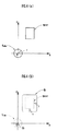
まず、本発明の移動装置の一実施形態であるロボットの構成について図1を用いて説明する。ロボット1は基体(胴体部)10と、基体10の上部に設けられた頭部11と、基体10の上部左右両側から延設された左右の腕体12と、基体10の下部から下方に延設された左右の脚体13とを備えている。添字「L」および「R」は左右を区別するために付されている。ロボット1は、再表03/090978号公報や、再表03/090979号公報に開示されているように、アクチュエータ(図示略)から伝達される力によって、人間の肩関節、肘関節、手根関節、股関節、膝関節、足関節等の複数の関節に相当する複数の関節部分において腕体12や脚体13を屈伸運動させることができる。ロボット1は、左右の脚体13のそれぞれの離床および着床を伴う動きによって自律的に移動することができる。基体10の鉛直方向に対する傾斜角度が調節されることによって、頭部11の高さが調節されうる。頭部11には、左右に並んでロボット1の前方に向けられた一対のCCDカメラ21が内蔵されている。頭部11がアクチュエータによって基体10に対して回動、傾動等されることでCCDカメラ21の撮像範囲が調節されうる。
First, the configuration of a robot which is an embodiment of the moving apparatus of the present invention will be described with reference to FIG. The
ロボット1はその歩行または走行動作を制御する制御システム100を備えている。制御システム100は、ハードウェアとしてのECUまたはコンピュータ(CPU,ROM,RAM,I/O等により構成されている。)と、ソフトウェアとしての本発明の「制御プログラム」とにより構成されている。制御プログラムはコンピュータのメモリに予め格納されていてもよいが、ロボット1から本発明の「監督システム」を構成するサーバに要求信号が送信されたことに応じて当該サーバによって制御プログラムがネットワークや人工衛星を介して当該コンピュータに配信または放送された上でそのメモリに格納されてもよい。
The
制御システム100は第1処理部110と、第2処理部120と、第3処理部130とを備えている。第1処理部110はロボット1、その位置および速度(向きおよび長さにより定義される速度ベクトルを意味する。以下同じ。)のそれぞれを、判定面における基準空間要素Q0、基準位置Oおよび基準速度v0のそれぞれとして認識する。また、第1処理部110は人間等の物体、その位置および速度のそれぞれを判定面における第1空間要素Q1、物体位置pおよび物体速度vのそれぞれとして認識する。さらに、第1処理部110は基準位置Oに対する物体位置pの相対位置、および基準速度v0に対する物体速度vの相対速度に応じて断続的または連続的に拡張された第1空間要素Q1を第2空間要素Q2として認識する。基準空間要素Q0の判定面における形状およびサイズはメモリ(図示略)から読み取られることで認識される。第2処理部120は第1処理部110による認識結果に基づき、判定面において基準空間要素Q0との接触可能性があるという「接触条件」を満たす第1空間要素Q1の有無を判定する。第3処理部130は第2処理部120によって判定面において接触条件を満たす第1空間要素Q1が存在すると判定されたことを要件として、第1処理部110により認識結果に基づき、判定面において基準空間要素Q0が第2空間要素Q2との接触を回避しうる経路を「第1行動計画要素」として設定する。
The
続いて、前記構成のロボットの機能について図2〜図9を用いて説明する。ロボット1はたとえば図6に一点鎖線で示されているような予め設定されている、または後述するように第3処理部130により設定された第1行動計画要素としての経路Rkに沿って歩行または走行している。
Next, functions of the robot having the above-described configuration will be described with reference to FIGS. The
第1処理部110が「第1処理」を実行する(図2/S110)。第1処理部110はロボット1、その位置および速度のそれぞれを、判定面における基準空間要素Q0、ロボット座標系における基準位置Oおよび基準速度v0のそれぞれとして認識する(図2/S112)。たとえば、ロボット1ならびにその位置および速度のそれぞれが図6に示されている判定面における点または微小な領域としての基準空間要素Q0、基準位置Oおよび基準速度v0として認識される。後述するようにCCDカメラ21を通じて得られた画像に基づき測定された物体xの位置は、ロボット1を基準とする相対位置に該当するので、ロボット1の位置測定は省略される。なお、物体xの測定位置が緯度および経度により表されている等、当該相対位置に該当しない場合、ロボット1の位置は当該相対位置の測定のために測定される。ロボット1の位置はそのGPS機能により得られる緯度および経度を表す信号や、ジャイロスコープから逐次出力されるロボット1の加速度を表す信号に基づいて測定される。ロボット1の速度はロボット1の時系列的な測定位置、ジャイロスコープから出力される信号、または脚体13の各関節角度および逆動力学モデル等に基づいて測定されうる。
The
また、第1処理部110は人間等の物体、その位置および速度のそれぞれを判定面における第1空間要素Q1、物体位置pおよび物体速度vのそれぞれとして認識する(図2/S114)。たとえば、図3に示されているようにロボット1の前方(CCDカメラ21の撮像範囲)に物体x1〜x4が存在する場合、各物体x1〜x4ならびにその位置および速度ベクトルのそれぞれが図6に示されているように判定面における第1空間要素(領域)Q11〜Q14、物体位置p1〜p4および物体速度v1〜v4として認識される。物体xの位置はCCDカメラ21を通じて得られた当該物体xの画像の解析に基づいて測定される。CCDカメラ21を通じて得られた画像に基づいて測定された位置は、ロボット1を基準とした相対位置に該当する。
In addition, the
判定面における基準空間要素Q0の形状およびサイズはメモリ(ロボット1の形状およびサイズが格納されている。)から読み取られることで認識されうる。また、判定面における第1空間要素Q1の形状およびサイズは、CCDカメラ21を通じて得られた画像に基づいて物体xの人間、犬(小形動物)等の種類が認識された後、当該認識結果に基づくメモリまたはデータベース(物体の種類、形状およびサイズが関連付けられて格納または管理されている。)の照会によって認識されうる。さらに、物体xの位置は、この物体xが有する通信装置等から送信された緯度および経度を表す信号が受信された上で、当該信号に基づいて測定または認識されてもよい。また、物体xの速度はこの物体xの位置の時間変化として測定されうる。判定面は緯度および経度により任意の点が特定される平面または曲面として定義されていてもよいが、CCDカメラ21を通じて得られる画像に基づいて認識されるロボット1の周辺における床面の傾斜角度や、段差や凹凸の有無等の形状に基づいて逐次定義されてもよい。
The shape and size of the reference space element Q 0 on the determination surface can be recognized by reading from the memory (the shape and size of the
ロボット1がその腕体12により箱を持っている場合や、基体10にロボット1に機能を付加するためのオプションとなる機器が取り付けられている場合等、当該箱や機器等の物体がロボット1と一体的に移動している状況では、当該一体的に移動しているロボット1および当該物体の形状およびサイズがロボット1の形状およびサイズとして認識されてもよい。
When the
ロボット1の外形特性(形状およびサイズ)に応じて拡張された、判定面における物体xの外形特性に応じた領域が、第1空間要素Q1として認識される。より具体的には、ロボット1および物体xのそれぞれの外形特性に応じた、判定面における外形特性を有する2つの領域のミンコフスキー和が第1領域Q1として認識される。たとえば、図4(a)に示されている判定面においてロボット1および物体xのそれぞれが円形状のロボット領域qrobotおよび矩形状の物体領域qobjectとして定義される場合、図4(b)に示されているように角が丸い矩形状の領域として表現される当該2つの領域のミンコフスキー和qrobot+qobjectが第1空間要素Q1として認識される。ロボット領域qrobotの中心が物体領域qobjectの輪郭をなぞるようにロボット領域qrobotを物体領域qobjectの周囲で移動させた場合、ロボット領域qrobotのうち物体領域qobjectからはみ出した部分が描く環状の領域と、物体領域qobjectとの和がミンコフスキー和に該当する。ロボット領域qrobotの形状およびサイズはロボット1のサイズ(または形状およびサイズ)に応じてメモリに予め格納されており、当該メモリから読み出されることにより認識される。物体領域qobjectはCCDカメラ21を通じて得られた画像に基づいて認識される物体xのサイズ(または形状およびサイズ)に応じた広がりを有する領域として認識される。なお、物体領域qobjectがそのまま第1空間要素Q1として認識されてもよく、ミンコフスキー和とは異なる方法によりロボット領域qrobotのサイズ等の外形特性に応じて拡張された物体領域qobjectが第1空間要素Q1として認識されてもよい。
Was extended in accordance with the contour characteristics of the robot 1 (shape and size), the area corresponding to the contour characteristics of the object x on the discriminant plane is recognized as the first spatial element Q 1. More specifically, the Minkowski sum of the two regions having the external characteristics on the determination surface according to the external characteristics of the
さらに、第1処理部110は基準位置Oおよび物体位置p、ならびに基準速度v0および物体速度vに応じて拡張された第1空間要素Q1を第2空間要素Q2として認識する(図2/S116)。たとえば図5(a)左側に示されている第1空間要素Q1が基準速度v0に対する物体速度vの相対速度(ベクトル)v−v0に応じた方向に連続的に引き伸ばされた結果として、図5(a)右側に示されているほぼまっすぐな帯状の第2空間要素Q2が認識される。第1空間要素Q1の引き伸ばし量は、第1空間要素の速度v、物体位置(相対位置)p(=p−O)、および相対速度v−v0に基づき、次式(1)にしたがって設定される。
(引き伸ばし量)=|p|・|v|/|v−v0|‥(1)
Further, the
(Stretching amount) = | p | ・ | v | / | v−v 0 | (1)
また、図5(b)左側に示されている第1空間要素Q1が相対速度v−v0にしたがって旋回するように連続的に引き伸ばされた結果として、図5(b)右側に示されている屈曲した帯状の第2空間要素Q2が認識される。前述した図3に示されている状況において、図6に示されているような第2空間要素Q21〜Q24が認識される。なお、図5(c)左側に示されている第1空間要素Q1が相対速度v−v0に応じた方向に断続的に引き伸ばされた結果として、図5(c)右側に示されている分離した空間要素からなる第2空間要素Q2が認識されてもよい。第1空間要素Q1の引き伸ばし部分は、物体の挙動状態(位置および速度)に応じて予測される当該物体の未来像に相当する。 Further, as a result of the first space element Q 1 shown on the left side of FIG. 5B being continuously stretched so as to turn according to the relative speed v−v 0 , it is shown on the right side of FIG. 5B. A bent belt-like second spatial element Q 2 is recognized. In the situation shown in FIG. 3 described above, the second spatial elements Q 21 to Q 24 as shown in FIG. 6 are recognized. As a result of the first spatial element Q 1 shown on the left side of FIG. 5C being intermittently stretched in the direction corresponding to the relative speed v−v 0 , the first space element Q 1 is shown on the right side of FIG. A second spatial element Q 2 consisting of separate spatial elements may be recognized. Stretched portion of the first spatial element Q 1 is equivalent to the future image of the object predicted in accordance with the object behavior state of (position and velocity).
続いて、第2処理部120が第1処理部110により認識された判定面における基準空間要素Q0と第1空間要素Q1との接触可能性の有無、すなわち、ロボット1と各物体との接触可能性の有無を判定する「第2処理」を実行する(図2/S120)。
Subsequently, the
第2処理部120は、判定面における基準空間要素Q0からの移動コストに関する「第1接触条件」を満たしている第1空間要素Q1の有無を判定する(図2/S122)。移動コストは判定面において基準空間要素が第1空間要素に接触するまでの所要時間および移動距離のうち一方または両方の関数として第3処理部130により評価される。図6に示されている基準空間要素Q0と、第1空間要素Q11〜Q14のそれぞれとの直線距離もしくは経路(一点鎖線)に沿った距離d、基準空間要素Q0および当該第1空間要素Q11〜Q14がそれぞれの基準速度v0および速度vを維持したまま移動し、基準空間要素Q0および第1空間要素Q11〜Q14のそれぞれに接するまでの所要時間t=(d/|v0−v|))、または当該距離dおよび所要時間tのうち一方もしくは両方の増加関数が移動コストとして評価される。
The
たとえば「移動コストが規定範囲{0,ε+(>0)}にあること」という第1接触条件が採用され、かつ、図6に一点鎖線で示されている経路Rkが最新の行動計画に応じて設定されている場合を考察する。この場合、4つの第1空間要素Q11〜Q14のうち、基準空間要素Q0に近い3つの第1空間要素Q11〜Q13が第1接触条件を満たしていると判定されうる。 For example, the first contact condition that “the movement cost is within a specified range {0, ε + (> 0)}” is adopted, and the route R k indicated by the one-dot chain line in FIG. 6 is the latest action plan. Consider the case where it is set according to. In this case, it can be determined that of the four first space elements Q 11 to Q 14 , three first space elements Q 11 to Q 13 that are close to the reference space element Q 0 satisfy the first contact condition.
第2処理部120は第1接触条件を満たす第1空間要素Q1が存在すると判定した場合(図2/S122‥YES)、当該第1空間要素Q1のうちロボット1の行動計画に応じた、判定面における基準位置Oから目標位置pdまで延びる基準空間要素Q0の経路RKとの位置関係に関する「第2接触条件」を満たしている第1空間要素Q1の有無を判定する(図2/S124)。
When the
たとえば「経路RKと第1空間要素Q1との交点または接点が存在すること」が第2接触条件として採用され、かつ、図6に一点鎖線で示されている経路RKが第1行動計画要素として設定されている場合を考察する。この場合、前記のように第1接触条件を満たしている3つの第1空間要素Q11〜Q13のうち、経路RKと交わっている第1空間要素Q12が第2接触条件を満たしていると判定される。なお「第1空間要素Q1までの最短距離またはその経路RKの一部もしくは全部に沿った累積または積分が所定値以下であること」や「基準位置Oにおける経路RKの接線(基準空間要素Q0の移動方向に延びている。)と第1空間要素Q1との交点または接点が存在すること」等が第2接触条件として採用されてもよい。 For example, "the route R K and intersection or contact between the first spatial element Q 1 is present" is adopted as the second contact condition, and the route R K shown in Figure 6 by a one-dot chain line first action Consider the case where it is set as a planning element. In this case, among the first first three meets a contact condition spatial elements Q 11 to Q 13 as the first spatial element Q 12 is also intersected with the path R K is satisfied the second contact condition It is determined that Note tangent (reference space of "the shortest distance or a path that accumulated or integral part or along the whole of R K is equal to or less than a predetermined value of the first up spatial element Q 1" and "reference position O in the path R K “The intersection or contact between the element Q 0 and the first space element Q 1 exists” may be adopted as the second contact condition.
前記のように「第1接触条件」および「第2接触条件」の両方を満たす第1空間要素Q1が存在する場合(図2/S122‥YES,S124‥YES)、基準空間要素Q0との接触可能性がある第1空間要素Q1が存在すると判定される。なお、第1接触条件および第2接触条件のうち一方のみを満たす第1空間要素Q1が存在する場合も、基準空間要素Q0との接触可能性がある第1空間要素Q1が存在すると判定されてもよい。 As described above, when the first space element Q 1 that satisfies both the “first contact condition” and the “second contact condition” exists (FIG. 2 / S122... YES, S124... YES), the reference space element Q 0 It is determined that there is a first spatial element Q 1 that can be contacted. In addition, even when there is a first space element Q 1 that satisfies only one of the first contact condition and the second contact condition, there is a first space element Q 1 that is likely to contact the reference space element Q 0. It may be determined.
そして、第2処理部120によって第2接触条件を満たしている第1空間要素Q1が存在すると判定された場合(図2/S124‥YES)、第3処理部130がすべての第2空間要素Q2との接触を回避しうるような基準空間要素Q0の新たな経路を第1行動計画要素として設定する「第3処理」を実行する(図2/S130)。
If it is determined by the
前記のように図6に示されている例では4つの第1空間要素Q11〜Q14のうち1つの第1空間要素Q12が第1および第2接触条件を満たすので、実線で示されているようにすべての第2空間要素Q21〜Q24と接触しない新たな経路RK+1が第1行動計画要素として設定される。これに応じて、ロボット1は先の第1行動計画要素としての図6に一点鎖線で示されている経路RKではなく、新たな第1行動計画要素としての図6に実線で示されている経路RK+1にしたがって移動する。
One of the first spatial element Q 12 of the first spatial element Q 11 to Q 14 of the four in the example shown in FIG. 6 because the first and second contact condition is satisfied as described above, is indicated by a solid line As shown, a new route R K + 1 that does not contact all the second space elements Q 21 to Q 24 is set as the first action plan element. In response to this, the
さらに、第3処理部130は判定面において基準空間要素Q0の基準位置Oおよび目的位置pdの距離|O−pd|が閾値δ以下になったか否か、すなわち、ロボット1画素の目的位置に到達したか否かを判定する(図2/S132)。なお、第2処理部120による判定結果が否定的(図2/S122‥NO,S124‥NO)であった場合も当該判定が実行される(図2/S132)。
Further, the
そして、当該判定結果が否定的であった場合(図2/S122‥NO)、前述の第1処理、第2処理等が再び実行される。たとえば図6に示されている状況から図7に示されている状況に変遷し、4つの第1空間要素Q11〜Q14のうち1つの第1空間要素Q12が再び第1および第2接触条件を満足していると判定された場合、図7において先の第1行動計画要素としての一点鎖線で示されている経路RK+1が、新たな第1行動計画要素としての実線で示されている新たな経路RK+2に変更される。一方、当該判定結果が肯定的であった場合(図2/S132‥YES)、前述の一連の処理が終了する。 And when the said determination result is negative (FIG. 2 / S122 ... NO), the above-mentioned 1st process, 2nd process, etc. are performed again. For example, a transition is made from the situation shown in FIG. 6 to the situation shown in FIG. 7, and one first spatial element Q 12 out of the four first spatial elements Q 11 to Q 14 becomes the first and second again. When it is determined that the contact condition is satisfied, the route R K + 1 indicated by the one-dot chain line as the first first action plan element in FIG. 7 is indicated by the solid line as the new first action plan element. It is changed to the new route R K + 2 shown. On the other hand, when the determination result is affirmative (FIG. 2 / S132... YES), the above-described series of processing ends.
前記機能を発揮するロボット1によれば、次の理由により第1行動計画要素としての経路Rkの変更頻度が抑制されている。
According to the
すなわち、判定面において移動コストに関する第1接触条件を満たす第1空間要素Q1のみが第2接触条件の充当性判定の対象とされている(図2/S122‥YES,S124参照)。これにより、ロボット1から遠くに存在する物体xに対応する第1空間要素Q1については、第2接触条件の充当性判定ひいては経路変更の要否判定の対象からはずされる。このため、すべての第1空間要素Q1が第2接触条件の充当性判定の対象とされる場合よりも経路Rkの変更頻度が抑制される。
That is, only the first space element Q 1 that satisfies the first contact condition regarding the movement cost on the determination surface is the target of the applicability determination of the second contact condition (see FIG. 2 / YES in S122, S124). As a result, the first spatial element Q 1 corresponding to the object x located far from the
また、判定面において第1接触条件を満たす第1空間要素Q1のうち少なくとも1つが、現在経路との位置関係に関する第2接触条件をさらに満たすことが経路Rkの変更要件とされている(図2/S124‥YES,S130参照)。第1空間要素Q1は判定面において広がりが比較的小さい空間要素として認識される(図5(a)〜図5(c)参照)。このため、第2空間要素Q2等、第1空間要素Q1よりも広がりが大きい空間要素を基準として第2接触条件の充足性が判定される場合よりも、第1行動計画要素としての経路Rkの変更頻度が低く抑制される。 In addition, it is a requirement for changing the route R k that at least one of the first spatial elements Q 1 satisfying the first contact condition on the determination surface further satisfies the second contact condition regarding the positional relationship with the current route ( (See FIG. 2 / S124... YES, S130). The first spatial element Q 1 is recognized as a spatial element having a relatively small spread on the determination surface (see FIGS. 5A to 5C). Therefore, the route as the first action plan element is greater than the case where the sufficiency of the second contact condition is determined with reference to a spatial element that is larger than the first spatial element Q 1 such as the second spatial element Q 2. The change frequency of R k is suppressed to be low.
さらに、判定面における第1空間要素Q1の形状およびサイズがデータベース等への照会により認識されうる。これにより、CCDカメラ21等による物体xのサイズ(または形状およびサイズ)の測定精度の限界のために物体xがその実際のサイズに鑑みて判定面における広がりが過大な第1空間要素Q1として認識される事態が回避されうる。そして、第1行動計画としての経路の変更頻度およびこれにともなうロボット1の移動方向等の変更頻度が低く抑制される。すなわち、CCDカメラ21等を通じた物体xの外形特性認識精度の限界のためにロボット1の経路が頻繁に変更される事態が回避される。
Further, the first shape and the size of the spatial element Q 1 on the discriminant plane can be recognized by a query to a database or the like. As a result, the object x is defined as the first spatial element Q 1 having an excessively large spread on the determination plane in view of the actual size due to the limit of the measurement accuracy of the size (or shape and size) of the object x by the
前記のように第1行動計画要素としての経路Rkの変更頻度が抑制される分だけ、ロボット1が移動方向を変化させる等、その挙動を変化させる頻度が抑制される。これにより、ロボット1の挙動変化に応じて人間等の物体xの挙動変化が誘発されてしまい、ロボット1と当該物体xとが接触する可能性がかえって高まるような事態が回避されうる。さらに、第1行動計画要素としての経路Rkの変更頻度が抑制される分だけ、当該経路変更に要する情報処理の負荷が軽減されうる。
As described above, the frequency with which the behavior of the
また、次のような理由によりロボット1が物体xとの接触を確実に回避する観点から適当な経路Rk+1が設定される。すなわち、前記のように判定面において第1接触条件および第2接触条件を満たす第1空間要素Q1が1つでも存在する場合、基準空間要素Q0が第2空間要素Q2との接触を回避しうるような新たな経路Rk+1が設定される(図2/S122‥YES,S124‥YES,S130、図6〜図7参照)。第2空間要素Q2は判定面において広がりが比較的大きい空間要素として認識される(図5(a)〜図5(c)参照)。このため、基準空間要素Q0が第1空間要素Q1等、第2空間要素Q2よりも広がりが小さい空間要素を基準として新たな経路が設定される場合よりも、ロボット1が物体xとの確実な接触回避の観点から適当な経路Rk+1が設定される。
Further, an appropriate route R k + 1 is set from the viewpoint of surely avoiding the
さらに、判定面における第1空間要素Q1の形状およびサイズがデータベース等への照会により認識され、第2空間要素Q2の形状およびサイズが当該第1空間要素Q1の形状およびサイズに基づいて定められる。これにより、CCDカメラ21等による物体xのサイズの測定精度の限界のために物体xがその実際のサイズに鑑みて判定面における広がりが過大な第2空間要素Q2として認識される事態が回避されうる。そして、第1行動計画としての経路が、物体xとの接触の観点から過剰に変更される事態が回避される。
Furthermore, the shape and size of the first space element Q 1 on the determination surface are recognized by a query to a database or the like, and the shape and size of the second space element Q 2 are based on the shape and size of the first space element Q 1. Determined. This avoids a situation in which the object x is recognized as the second spatial element Q 2 having an excessively large spread on the determination plane in view of the actual size due to the limit of the measurement accuracy of the size of the object x by the
続いて、一の判定面のみならず、複数の判定面のそれぞれにおいて各空間要素Q0,Q1およびQ2が認識され、かつ、当該複数の判定面のうちいずれかにおいて第1および第2接触条件を満たす第1空間要素Q1が存在することが第1行動計画要素の変更要件とされている実施形態について説明する。 Subsequently, each of the spatial elements Q 0 , Q 1, and Q 2 is recognized not only on one determination plane but also on each of the plurality of determination planes, and the first and second ones on any of the plurality of determination planes. An embodiment in which the presence of the first spatial element Q 1 that satisfies the contact condition is regarded as a change requirement for the first action plan element will be described.
例として図8に示されているようにロボット1が、ロボット1よりも背の低い猫や犬などの第1物体x1と、ロボット1と背の高さが同程度の人間などの第2物体x2との間をすれ違うように歩行する状況を考える。
For example, as shown in FIG. 8, the
この状況でロボット1、第1物体x1および第2物体x2のそれぞれが1つの判定面Pでのみ認識された場合、当該判定面Pでは図9(c)に示されているような基準空間要素Q0ならびに第1空間要素Q11およびQ12として認識される場合がある。この場合、第1および第2接触条件を満たす第1空間要素Q1が存在すると判定され、先の経路Rkが新たな経路Rk+1に変更されうる(図2/S124‥YES,S130参照)。すなわち、ロボット1等の立体的外形特性が考慮されていないため、第1空間要素Q1が大きい空間要素として認識され、この分だけロボット1が物体xとの接触を回避するための新たな第1行動計画要素が設定される可能性が高くなる。
In this situation, when each of the
その一方、複数の判定面のそれぞれにおいて基準空間要素Q0等が認識されることにより、ロボット1および各物体xのそれぞれの立体的形状特性に鑑みて適当な頻度で経路が変更され、かつ、ロボット1および各物体xの確実な接触回避の観点から適当な経路が設定されうる。
On the other hand, by recognizing the reference space element Q 0 or the like on each of the plurality of determination surfaces, the path is changed at an appropriate frequency in view of the three-dimensional shape characteristics of the
たとえば前記状況で床面からの高さh1の判定平面P(h1)および高さh2(>h1)の判定平面P(h2)のそれぞれにおいて基準空間要素Q0等が認識される場合を考える。この場合、判定面P(h1)においては第1物体x1および第2物体x2のそれぞれが図9(a)に示されているような第1空間要素Q11およびQ12として認識される。また、高さh2(>h1)の判定面P(h2)においては第2物体x2のみが図9(b)に示されているような第1空間要素Q12として認識される。判定面P(h2)では第1物体x1は認識されていない。これは、第1物体x1の背が高さh2に満たないからである。 For example, in the above situation, the reference space element Q 0 or the like is recognized in each of the determination plane P (h 1 ) having a height h 1 from the floor and the determination plane P (h 2 ) having a height h 2 (> h 1 ). Consider the case. In this case, on the determination plane P (h 1 ), the first object x 1 and the second object x 2 are recognized as the first spatial elements Q 11 and Q 12 as shown in FIG. The Also be in the discriminant plane P of the height h 2 (> h 1) ( h 2) recognized as the first spatial element Q 12, such as shown in the second object x 2 although only 9 (b) . The first object x 1 is not recognized on the determination plane P (h 2 ). This is because the height of the first object x 1 is less than the height h 2 .
また、第2物体x2が判定面P(h2)では比較的大きい第1空間要素Q12として認識される一方、判定面P(h1)では比較的小さい第1空間要素Q12として認識されている。これは、ロボット1の上半身が腕体12等の存在のため下半身よりもサイズが大きく(図1参照)、第2物体x2である人間も同様に上半身が下半身よりもサイズが大きいためである。別の言い方をすると、ロボット1および第2物体x2の上半身にかかる判定面P(h2)におけるロボット領域qrobotおよび物体領域qobjectのミンコフスキー和のサイズがロボット1および物体x2の下半身にかかる判定面P(h1)におけるミンコフスキー和qrobot+qobjectよりも大きくなるからである(図4参照)。これら2つの判定面P(h1)およびP(h2)の両方において基準空間要素Q0から目的位置pdまで延びる経路Rkと第1空間要素Q1とは交わらないので第2接触条件を満たす第1空間要素Q1が存在しないと判定され、第1行動計画要素としての経路Rkはそのままに維持される(図2/S124‥NO参照)。
The second object x 2 is recognized as a relatively large first space element Q 12 on the determination plane P (h 2 ), while it is recognized as a relatively small first space element Q 12 on the determination plane P (h 1 ). Has been. This is because the upper body of the
これにより、ロボット1および物体xのそれぞれの3次元形状およびサイズに鑑みた適当な頻度で経路Rkが変更されうる。すなわち、ロボット1および物体xのそれぞれは一般的に形状およびサイズが床面からの高さ等、位置に応じて変化するという外形特性を有している。このため、複数の判定面のそれぞれにおいて認識された第1空間要素Q1の形状およびサイズに、ロボット1および物体xのそれぞれの異なる箇所(高さ)の形状およびサイズが反映されうる。これにより、ロボット1および物体xのそれぞれの立体的外形特性、位置および速度等の挙動状態に鑑みて、基準空間要素Q0として認識されたロボット1が第1空間要素Q1として認識された物体xとの接触を回避する観点から適当な頻度で第1行動計画要素としての経路Rkが変更されうる。
As a result, the path R k can be changed at an appropriate frequency in consideration of the three-dimensional shapes and sizes of the
また、複数の判定面のすべてにおいて基準空間要素Q0が第2空間要素Q2との接触を回避する経路Rk+1が第1行動計画要素として設定される。これにより、ロボット1および物体のそれぞれの3次元的な形状およびサイズに鑑みて、両者の接触回避の観点から適当な経路Rk+1が設定されうる。
In addition, a route R k + 1 that avoids contact of the reference space element Q 0 with the second space element Q 2 is set as the first action plan element in all of the plurality of determination surfaces. Thereby, in view of the three-dimensional shapes and sizes of the
したがって、ロボット1が、人間等の物体xの挙動変化を誘発する頻度を低く抑制しながら、当該物体xとの接触を回避して移動を継続することができる。
Therefore, the
また、ロボット1および物体xのそれぞれの外形特性に応じた2つの領域q0およびqのミンコフスキー和q0+qが第1空間要素Q1として認識される。これにより、ロボット1および物体xのそれぞれのサイズおよび形状が判定面における第1空間要素Q1のサイズおよび形状にまとめて反映されうる。このため、判定面における基準空間要素Q0の点または微小領域としての簡易的な取り扱い、ひいては基準空間要素Q0との接触可能性がある第1空間要素Q1の有無の判定等の容易化が図られながらも、当該判定精度の向上または維持が図られうる。
Further, the Minkowski sum q 0 + q of the two regions q 0 and q corresponding to the external characteristics of the
なお、前記制御方法がロボット1のように左右一対の脚体の動作によって移動するロボットのほか、3つ以上の脚体の動作によって移動するロボットや、車輪式移動ロボット(自動車)等、移動機能を有するあらゆる装置に適用されてもよい。
In addition to the robot that moves by the movement of a pair of left and right legs like the
また、移動コストに関する規定範囲の下限値として0ではなく正値が採用された場合、移動コストが当該下限値未満である場合には第1接触条件が満たされず、新たな第1行動計画要素としての経路Rkは変更されない(図2/S122‥NO参照)。これにより、物体xがロボット1の近くにあるため、ロボット1の挙動を変化させると物体xの挙動変化を誘発し、かえって両者の接触可能性が高くなる可能性がある状態で、ロボット1の移動方向が変更される事態が回避されうる。
In addition, when a positive value is adopted instead of 0 as the lower limit value of the specified range regarding the movement cost, the first contact condition is not satisfied when the movement cost is less than the lower limit value, and the new first action plan element The route R k is not changed (see NO in FIG. 2 / S122). As a result, since the object x is near the
続いて、本発明の移動装置の他の実施形態についてさらに図10〜図16を用いて説明する。当該他の実施形態によれば、ロボット1は「第2行動計画要素」にしたがってその姿勢を制御する。
Next, another embodiment of the moving device of the present invention will be described with reference to FIGS. According to the other embodiment, the
第1処理部110は第2行動計画要素に基づいて定まるロボット1の端点軌道trのうち少なくとも一部を含む判定面において基準空間要素Q0、第1空間要素Q1および第2空間要素Q2を認識する。第2処理部120は第1処理部110による認識結果に基づき、第1および第2接触条件を満たす第1空間要素Q1の有無を判定する。第3処理部130は第2処理部120により当該接触条件を満たす第1空間要素Q1が存在すると判定されたことを要件として、端点軌道trの変更をともなう第2行動計画要素の変更を仮定する。すなわち、第3処理部130は第2処理部120により当該接触条件を満たす第1空間要素Q1が存在すると判定されたことを要件として、ただちに前記のように第1行動計画要素としての経路を変更するのではない点において前記実施形態と相違する。
The
第1処理部110は第3処理部130により仮定された当該変更後の第2行動計画要素にしたがってロボット1の姿勢が制御されたという仮定のもとで、端点軌道trのうち少なくとも一部を含む判定面においてあらためて基準空間要素Q0、第1空間要素Q1および第2空間要素Q2を認識する。第2処理部120は第1処理部110による当該仮定のもとでの認識結果に基づき、判定面において接触条件を満たす第1空間要素Q0の有無を判定する。第3処理部130は当該仮定のもとで第2処理部120により当該接触条件を満たす第1空間要素Q1が存在すると判定されたことを要件として、第1処理部110による認識結果に基づき、判定面において基準空間要素Q0が第2空間要素Q2との接触を回避しうるように第1行動計画要素としての経路Rk+1を変更する。その一方、第3処理部130は当該仮定のもとで第2処理部120により当該接触条件を満たす第1空間要素Q1が存在しないと判定されたことを要件として、当該仮定どおりに第2行動計画要素を設定する。
The
前記構成のロボット1の機能について図10〜図16を用いて説明する。
The function of the
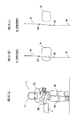
まず、図10(a)に示されているように第2行動計画要素として頭部(第1部分)11の波状の上端点軌道tr1(変更前)が定義され、図16(a)に示されているように当該上端点軌道tr1(変更前)の全部を含む波状の第1判定面P1(変更前)において第1および第2接触条件を満たす第1空間要素Q1の有無が判定される場合を考える。頭部11の上端点軌道tr1(変更前)が波状となっているのは着床状態にある脚体13の膝関節角度等の変化をともなう姿勢の変化に応じて頭部11が上下動するためである。なお、ロボット1の「第1部分」としては頭部11のほか、左右の腕体12が対象とされてもよい。また、波状の上端点軌道tr1(変更前)の全部ではなく一部(当該波の極大点群または極小点群など。)のみを含む、図16(b)に示されているような平面が第1判定面P1(変更前)として定義されてもよい。
First, as shown in FIG. 10A, a wavy upper end point trajectory tr 1 (before change) of the head (first portion) 11 is defined as a second action plan element, and FIG. As shown, the presence or absence of the first spatial element Q 1 that satisfies the first and second contact conditions on the wavy first determination plane P 1 (before change) including the entire upper end point trajectory tr 1 (before change). Suppose that is determined. The upper end point trajectory tr 1 (before change) of the
図10(a)に示されている頭部11の上端点軌道tr1(変更前)は物体xに接触しているので、ロボット1が現状の第1および第2行動計画要素にしたがって移動を継続すると図11(a)に破線で示されているように頭部11が物体xに接触してしまう。このため、第2処理部120によって第1判定面P1(変更前)において第1接触条件に加え、図11(b)に示されているように第1行動計画要素としての経路Rkと交わるという第2接触条件を満たす第1空間要素Q1が存在すると判定される。第1行動計画要素としての経路Rkは第2行動計画要素としての頭部13の上端点軌道tr1(変更前)と同一であってもよい。
Since the upper end point trajectory tr 1 (before change) of the
第2処理部120による当該肯定的な判定結果に応じて、第3処理部130により頭部11の上端点軌道tr1(変更前)を下降させるような第2行動計画要素が仮定される。これにより、たとえば少なくとも図11(b)に示されている区間s01〜s02にわたり、図10(b)に示されているようにロボット1がその基体10の鉛直方向への傾斜角度を増加させることにより前傾姿勢をとって頭部11を下げながら移動する、頭部11の上端点軌道tr1(変更後)が第2行動計画要素として仮定される。
A second action plan element that lowers the upper end point trajectory tr 1 (before change) of the
続いて、第1処理部110により当該仮定のもとで、頭部11の波状の上端点軌道tr1(変更後)を含む波状の第1判定面P1(変更後)において基準空間要素Q0等が認識される(図2/S110参照)。
Subsequently, the
図10(b)に示されている頭部11の上端点軌道tr1(変更後)は物体xに接触しないので、ロボット1が当該仮定された第2行動計画要素にしたがって移動すると図11(a)に実線で示されているように頭部11が物体xの下方に位置する。このため、第2処理部120によって第1判定面P1(変更後)において図11(c)に示されているように第1行動計画要素としての経路Rkと接するまたは交わるという第2接触条件を満たす第1空間要素Q1が存在しないと判定される。
Since the upper end point trajectory tr 1 (after change) of the
第2処理部120による当該判定結果に応じて、第3処理部130によって当該過程どおりに第2行動計画要素が設定される。これにより、たとえば図10(b)に示されているようにロボット1がその基体10の鉛直方向への傾斜角度を増加させることにより前傾姿勢をとって頭部11を下げながら移動する、頭部11の上端点軌道tr1(変更後)が第2行動計画要素として設定される。ロボット1はこの新たな第2行動計画要素にしたがってその姿勢を制御しながら移動する。これにより、先の第1行動計画要素としての経路Rkを変更することなく、物体xとの接触を回避しながらその目的位置まで移動することができる。また、ロボット1の移動方向の変更頻度を低く抑え、物体xの予期せぬ挙動変化を誘発する事態が回避されうる。
In accordance with the determination result by the
一方、第2処理部120によって第1判定面P1(変更後)において第1および第2接触条件を満たす第1空間要素Q1が存在すると判定されたことに応じて、第3処理部130により前記のように第2空間要素Q2との接触を回避しうるような基準空間要素Q0の経路Rk+1が新たな第1行動計画要素として設定される(図2/S130、図6参照)。ロボット1は第1行動計画要素としての当該変更後の経路Rk+1にしたがって移動することにより、物体xとの接触を回避しながらその目的位置まで移動することができる。
On the other hand, in response to the determination by the
また、図12(a)に示されているように第2行動計画要素として右脚体(第2部分)13Rの上下動する波状の下端点軌道tr2(変更前)が設定され、当該下端点軌道tr2(変更前)の全部を含む波状の第2判定面P2(変更前)(図16(a)参照)において第1および第2接触条件を満たす第1空間要素Q1の有無が判定される場合を考える。脚体13の下端点軌道tr2(変更前)が上下動する波状となっているのはロボット1がその脚体13の着床および離床を繰り返しながら移動するためである。なお、ロボット1の「第2部分」としては一方の脚体13のみならず両方の脚体13や、各腕体12が対象とされてもよい。
Also, as shown in FIG. 12 (a), a wavy lower end point trajectory tr 2 (before change) of the right leg (second portion) 13R is set as the second action plan element, and the lower end Presence / absence of the first spatial element Q 1 that satisfies the first and second contact conditions on the wavy second determination plane P 2 (before change) (see FIG. 16A) including the entire point trajectory tr 2 (before change). Suppose that is determined. The lower end point trajectory tr 2 (before change) of the leg 13 has a wavy shape that moves up and down because the
図12(a)に示されている右脚体13Rの下端点軌道tr2(変更前)は物体xに接触しているので、ロボット1が現状の第1および第2行動計画要素にしたがって移動を継続すると図13(a)に破線で示されているように右脚体13Rが物体xに接触してしまう(ロボット1がつまづいてしまう)。このため、第2処理部120によって第2判定面P2(変更前)において第1接触条件に加え、図13(b)に示されているように第1行動計画要素としての経路Rkと交わるという第2接触条件を満たす第1空間要素Q1が存在すると判定される。なお、第1行動計画要素としての経路Rkは第2行動計画要素としての各脚体13の下端点軌道tr2(変更前)と同一であってもよい。
Since the lower end point trajectory tr 2 (before change) of the
第2処理部120による当該肯定的な判定結果に応じて、第3処理部130により右脚体13Rの下端点軌道tr2(変更前)を上昇させるような第2行動計画要素が仮定される。これにより、たとえば少なくとも図13(b)に示されている区間s01〜s02にわたり、図12(b)に示されているようにロボット1が離床状態にある右脚体13Rを通常よりも高く持ち上げることで物体xをまたぐように移動する、右脚体13Rの下端点軌道tr2(変更後)が第2行動計画要素として仮定される。この場合、図13(b)に示されている区間s01〜s02の距離がロボット1の歩幅よりも小さいことが当該第2行動計画要素の仮定のための要件とされている。
In accordance with the positive determination result by the
続いて、第1処理部110により当該仮定のもとで、右脚体13Rの波状の下端点軌道tr2(変更後)を含む波状の第2判定面P2(変更後)において基準空間要素Q0等が認識される(図2/S110参照)。
Subsequently, under the assumption, the
図12(b)に示されている右脚体13Rの上端点軌道tr2(変更後)は物体xに接触しないので、ロボット1が当該仮定された第2行動計画要素にしたがって移動すると図13(a)に実線で示されているように右脚体13Rが物体xの上方に位置する。このため、第2処理部120によって第2判定面P2(変更後)において図13(c)に示されているように第1行動計画要素としての経路Rkと接するまたは交わるという第2接触条件を満たす第1空間要素Q1が存在しないと判定される。
Since the upper end point trajectory tr 2 (after change) of the
第2処理部120による当該否定的な判定結果に応じて、第3処理部130によって当該仮定どおりに第2行動計画要素が設定される。これにより、たとえば図12(b)に示されている右脚体13Rの下端点軌道tr2(変更後)が第2行動計画要素として設定される。なお、ロボット1が物体xをまたぐために、必要に応じて物体xの手前でその歩幅を調節することも第2行動計画要素として設定されてもよい。ロボット1はこの新たな第2行動計画要素にしたがってその姿勢を制御しながら移動する。これにより、先の第1行動計画要素としての経路Rkを変更することなく、物体xとの接触(つまづき)を回避しながらその目的位置まで移動することができる。また、ロボット1の移動方向の変更頻度を低く抑えることで、物体xの予期せぬ挙動変化を誘発する事態が回避されうる。
In accordance with the negative determination result by the
一方、第2処理部120によって第2判定面P2(変更後)において第1および第2接触条件を満たす第1空間要素Q1が存在すると判定されたことに応じて、第3処理部130により前記のように第2空間要素Q2との接触を回避しうるような基準空間要素Q0の経路Rk+1が新たな第1行動計画要素として設定される(図2/S130、図6参照)。ロボット1は第1行動計画要素としての当該変更後の経路Rk+1にしたがって移動することにより、物体xとの接触を回避しながらその目的位置まで移動することができる。
On the other hand, when the
さらに、図14(a)に示されているように第2行動計画要素として右腕体(第3部分)12Rの波状の右端点軌道tr3(変更前)が設定され、当該右端点軌道tr3(変更前)の全部を含む第3判定面P3(変更前)(図16(a)参照)において、第1および第2接触条件を満たす第1空間要素Q1の有無が判定される場合を考える。右腕体12の右端点軌道tr 3 (変更前)が左右に変動する波状となっているのはロボット1がその姿勢安定のために腕体12の振り動作を繰り返しながら移動するためである。なお、ロボット1の「第3部分」としては一方の腕体12のみならず両方の腕体12、各脚体13が対象とされてもよい。
Furthermore, Figure 14 right arm member as the second action plan element as shown in (a) (third part) 12R corrugated right end trajectory tr 3 of (before change) is set, the right end trajectory tr 3 When the presence or absence of the first spatial element Q 1 satisfying the first and second contact conditions is determined on the third determination plane P 3 including all of (before change) (before change) (see FIG. 16A). think of. The right end point trajectory tr 3 right arm member 12 (before the change) is a wave that fluctuates to the left and right are for the
図14(a)に示されている右腕体12Rの右端点軌道tr3(変更前)は物体xに接触しているので、ロボット1が現状の第1および第2行動計画要素にしたがって移動を継続すると図15(a)に破線で示されているように右腕体12Rが物体xに接触してしまう。このため、第2処理部120によって第3判定面P3(変更前)において第1接触条件に加え、図15(b)に示されているように第1行動計画要素としての経路Rkと交わるという第2接触条件を満たす第1空間要素Q1が存在すると判定される。
Since the right end point trajectory tr 3 (before change) of the
第2処理部120による当該肯定的な判定結果に応じて、第3処理部130により右腕体12Rの右端点軌道tr3(変更前)を左側に移動させるような第2行動計画要素が仮定される。これにより、たとえば少なくとも図15(b)に示されている区間s01〜s02にわたり、図14(b)に示されているようにロボット1が右腕体12Rを左側に移動させる右腕体12Rの右端点軌道tr3(変更後)が第2行動計画要素として仮定される。
In accordance with the positive determination result by the
続いて、第1処理部110により当該仮定のもとで、右腕体12Rの波状の右端点軌道tr3(変更後)を含む波状の第3判定面P3(変更後)において基準空間要素Q0等が認識される(図2/S110参照)。
Subsequently, under the assumption, the
図14(b)に示されている右腕体12Rの右端点軌道tr3(変更後)は物体xに接触しないので、ロボット1が当該仮定された第2行動計画要素にしたがって移動すると図15(a)に実線で示されているように右腕体12Rが物体xから横向きに離れて位置する。このため、第2処理部120によって第3判定面P3(変更後)において図15(c)に示されているように第1行動計画要素としての経路Rkと接するまたは交わるという第2接触条件を満たす第1空間要素Q1が存在しないと判定される。
Since the right end point trajectory tr 3 (after change) of the
第2処理部120による当該否定的な判定結果に応じて、第3処理部130によって当該仮定どおりに第2行動計画要素が設定される。これにより、たとえば図14(b)に示されている右腕体12Rの右端点軌道tr3(変更後)が第2行動計画要素として設定される。ロボット1はこの新たな第2行動計画要素にしたがってその姿勢を制御しながら移動する。これにより、先の第1行動計画要素としての経路Rkを変更することなく、物体xとの接触を回避しながらその目的位置まで移動することができる。また、ロボット1の移動方向の変更頻度を低く抑えることで、物体xの予期せぬ挙動変化を誘発する事態が回避されうる。
In accordance with the negative determination result by the
一方、第2処理部120によって第3判定面P3(変更後)において第1および第2接触条件を満たす第1空間要素Q1が存在すると判定されたことに応じて、第3処理部130により前記のように第2空間要素Q2との接触を回避しうるような基準空間要素Q0の経路Rk+1が新たな第1行動計画要素として設定される(図2/S130、図6参照)。ロボット1は第1行動計画要素としての当該変更後の経路Rk+1にしたがって移動することにより、物体xとの接触を回避しながらその目的位置まで移動することができる。
On the other hand, in response to the determination by the
一または複数の第1判定面P1、一または複数の第2判定面P2および一または複数の第3判定面P3のうちから任意に選択された判定面における接触条件を満たす第1空間要素Q1の有無判定、および当該判定結果に応じた第1または第2行動計画要素の変更が組み合わせられてもよい。これにより、ロボット1がその姿勢を安定に維持できるという条件下で、前傾姿勢をとって頭部11を下げながら、離床状態にある脚体13を通常より高く持ち上げる等、さまざまに姿勢を制御して物体xとの接触を回避しながら移動することができる。
A first space that satisfies a contact condition on a determination surface arbitrarily selected from one or more first determination surfaces P 1 , one or more second determination surfaces P 2, and one or more third determination surfaces P 3. presence determining element Q 1, and the first or second action plan element of may be combined changes in accordance with the determination result. This allows the
なお、基準空間要素Q0ひいてはロボット1の速度の方向および大きさのうち一方または両方の変化率が閾値以下とすることが(付加的な)第1行動計画要素として設定されてもよい。これにより、第1行動計画要素の変更によるロボット1の過剰な速度変化およびこれにともなう挙動変化が抑制されうる。また、物体xの予期せぬ挙動変化を誘発し、ロボット1と物体xとの接触可能性をかえって高めるような事態が回避されうる。さらに、ロボット1にその能力を超えた速度変化またはこれにともなう挙動変化を強いる事態が回避されうる。
Note that it may be set as the (additional) first action plan element that the rate of change of one or both of the direction and magnitude of the speed of the reference space element Q 0 and the robot 1 is not more than a threshold value. Thereby, the excessive speed change of the
また、基準空間要素Q0ひいてはロボット1の速度の大きさが向きよりも優先的に変更されるように第1行動計画要素が設定されてもよい。この場合、ロボット1の速度の方向(移動方向)の変化が物体の挙動変化を誘発しやすい傾向があることに鑑みて、ロボット1の速度の大きさ(速さ)が向きよりも優先的に変更される。これにより、物体xの挙動変化を誘発するようなロボット1の挙動変化の頻度が低く抑えられうる。
Further, the first action plan element may be set so that the reference space element Q 0 and thus the speed of the
さらに、第3処理部130がロボット1の移動方向の予告を「第3行動計画要素」として設定し、制御システム100が第3行動計画にしたがってロボット1の搭載機器の動作を制御してもよい。たとえば、搭載機器としてのアクチュエータの動作が制御されることにより、基体10、頭部11、腕部12および脚部13等、人間の身体部分に対応する可動部分の第3行動計画要素にしたがった動きによりロボット1の移動方向が予告されてもよい。これにより、頭部11の正面(顔)の向きを変える、腕部12の姿勢を変える、基体10の上部を下部に対してひねる等、人間にとって馴染みやすい行動様式によって当該人間(物体x)に違和感を覚えさせることなくロボット1の移動方向を明確に認識させることができる。そして、物体xの方向転換等の行動を誘起し、ロボット1と物体xとの接触可能性を低減させることができる。また、ロボット1に方向指示器、光照射装置、または音声出力装置等を搭載機器としてもたせ、第3行動計画要素にしたがって方向指示器の点灯、光照射装置によるビームの照射、音声出力装置による音声の出力が制御されることで、ロボット1の移動方向が予告されてもよい。
Further, the
1‥ロボット(移動装置)、100‥制御システム、112‥第1処理部、120‥第2処理部、130‥第3処理部、x‥物体、Q0‥基準空間要素、Q1‥第1空間要素、Q2‥第2空間要素
1 ‥ robot (mobile apparatus), 100 ‥
Claims (19)
前記第2行動計画要素に基づいて定まる前記移動装置の端点軌道のうち少なくとも一部を含む判定面において、前記移動装置の現在像、物体の現在像および前記現在像よりも空間的広がりが大きい、前記物体の挙動状態に応じた前記物体の断続的または連続的な未来像のそれぞれを基準空間要素、第1空間要素および前記第1空間要素よりも空間的な広がりが大きい第2空間要素のそれぞれとして認識する第1処理部と、
前記第1処理部による認識結果に基づき、前記判定面において接触条件としての前記第1行動計画要素としての経路に沿って移動したときの前記基準空間要素と前記第1空間要素との交点または接点があるという第2接触条件、または、前記基準空間要素から前記第1空間要素までの距離が長くなるほど高くなるように定義されている移動コストが規定範囲内であるという第1接触条件および前記第2接触条件を満たす前記第1空間要素の有無を判定する第2処理部と、
前記第2処理部により前記判定面において前記接触条件を満たす前記第1空間要素が存在すると判定されたことを要件として前記端点軌道の変更をともなう前記第2行動計画要素を仮定し、前記仮定のもとで前記第1処理部に前記変更後の前記端点軌道のうち少なくとも一部を含む新たな判定面において前記基準空間要素、前記第1空間要素および前記第2空間要素を認識させ、かつ、前記新たな判定面において前記接触条件を満たす前記第1空間要素の有無を判定させ、
前記第2処理部により前記新たな判定面において前記接触条件を満たす前記第1空間要素がなおも存在すると判定されたことを要件として、前記変更前の前記端点軌道のうち少なくとも一部を含む前記判定面において、前記第1処理部による認識結果に基づき、前記基準空間要素が前記第2空間要素との接触を回避しうるように前記第1行動計画要素としての経路を変更する一方、前記第2処理部により前記新たな判定面において前記接触条件を満たす前記第1空間要素が存在しないと判定されたことを要件として前記仮定どおりに新たな前記第2行動計画要素を設定する第3処理部とを備えていることを特徴とする移動装置。 A control system, and each of the position and orientation is independent according to each of a first action plan element that defines a change mode of position and a second action plan element that defines a change mode of posture by controlling the operation by the control system. a mobile device for adjusting the said control system,
In the determination surface including at least a part of the end point trajectory of the moving device determined based on the second action plan element, the current image of the moving device, the current image of the object, and the spatial spread are larger than the current image. Each of the intermittent or continuous future images of the object according to the behavior state of the object is represented by a reference space element, a first space element, and a second space element having a larger spatial extent than the first space element, respectively. A first processing unit recognized as
Based on a recognition result by the first processing unit , an intersection or a contact point between the reference space element and the first space element when moving along a route as the first action plan element as a contact condition on the determination surface The first contact condition that the movement cost defined to be higher as the distance from the reference space element to the first space element is longer is within a specified range, and the first contact condition a second processing unit for determining the presence or absence of the first spatial element that satisfies the second contact condition,
Assuming that the second processing unit with the change of the end point trajectory is assumed as a requirement that the second processing unit has determined that the first spatial element satisfying the contact condition exists on the determination surface, the assumption Originally, the first processing unit is made to recognize the reference space element, the first space element, and the second space element in a new determination plane including at least a part of the end point trajectory after the change, and Determining whether or not the first spatial element satisfies the contact condition on the new determination surface;
The second processing unit includes, as a requirement that the first spatial element that satisfies the contact condition still exists on the new determination surface, including at least a part of the end point trajectory before the change. In the determination plane, based on the recognition result by the first processing unit , the route as the first action plan element is changed so that the reference space element can avoid contact with the second space element, while the first space A third processing unit that sets a new second action plan element according to the assumption on the condition that it is determined by the two processing units that the first spatial element that satisfies the contact condition does not exist on the new determination plane And a moving device.
前記第1処理部が前記端点軌道としての前記移動装置の第1部分の上端点軌道のうち少なくとも一部を含む前記判定面としての第1判定面において前記基準空間要素、前記第1空間要素および前記第2空間要素を認識し、
前記第2処理部が前記第1処理部による認識結果に基づいて前記第1判定面において前記接触条件を満たす前記第1空間要素の有無を判定し、
前記第2処理部により前記第1判定面において前記接触条件を満たす前記第1空間要素が存在すると判定されたことを要件として、前記第3処理部が前記第1部分の上端点軌道の下降を前記第2行動計画要素として仮定することを特徴とする移動装置。 The mobile device according to claim 1, wherein
The reference spatial element in the first discriminant plane as the discriminant plane including at least part of the upper end trajectory of the first portion of the first processing unit is the mobile device serving as the end point trajectory, said first spatial element and Recognizing said second spatial element;
The second processing unit determines the presence or absence of the first spatial element that satisfies the contact condition on the first determination surface based on a recognition result by the first processing unit,
The third processing unit lowers the upper end point trajectory of the first portion on the condition that the second processing unit determines that the first spatial element satisfying the contact condition exists on the first determination surface. A moving apparatus which is assumed as the second action plan element.
前記第1部分として鉛直方向に対して傾動可能な基体の上側に設けられた頭部を備え、
前記第2処理部により前記第1判定面において前記接触条件を満たす前記第1空間要素が存在すると判定されたことを要件として、前記第3処理部が前記基体の鉛直方向に対する傾斜角度を増加させることによる前記頭部の上端点軌道の下降を前記第2行動計画要素として設定することを特徴とする移動装置。 The mobile device according to claim 2, wherein
A head provided on the upper side of the base body tiltable with respect to the vertical direction as the first part;
The third processing unit increases the inclination angle of the base body with respect to the vertical direction on condition that the second processing unit determines that the first spatial element satisfying the contact condition exists on the first determination surface. Accordingly, the lowering of the upper end point trajectory of the head is set as the second action plan element.
前記第1部分として基体から延設された腕体を備え、
前記第2処理部により前記第1判定面において前記接触条件を満たす前記第1空間要素が存在すると判定されたことを要件として、前記第3処理部が前記腕体の姿勢変化による前記腕体の上端点軌道の下降を前記第2行動計画要素として設定することを特徴とする移動装置。 The mobile device according to claim 2, wherein
An arm body extending from the base body as the first portion;
On condition that the second processing unit has determined that the first spatial element satisfying the contact condition exists on the first determination surface, the third processing unit is configured so that the arm body is changed by the posture change of the arm body. A moving apparatus, wherein the lowering of the upper end point trajectory is set as the second action plan element.
前記第1処理部が前記端点軌道としての前記移動装置の第2部分の下端点軌道のうち少なくとも一部を含む前記判定面としての第2判定面において前記基準空間要素、前記第1空間要素および前記第2空間要素を認識し、
前記第2処理部が前記第1処理部による認識結果に基づいて前記第2判定面において前記接触条件を満たす前記第1空間要素の有無を判定し、
前記第2処理部により前記第2判定面において前記接触条件を満たす前記第1空間要素が存在すると判定されたことを要件として、前記第3処理部が前記第2部分の下端点軌道の上昇を前記第2行動計画要素として仮定することを特徴とする移動装置。 The mobile device according to claim 1, wherein
The reference spatial element in the second discriminant plane as the discriminant plane including at least part of the lower end trajectory of the second part of the mobile device serving as the first processing unit is the endpoint trajectory, said first spatial element and Recognizing said second spatial element;
The second processing unit determines the presence or absence of the first spatial element that satisfies the contact condition on the second determination surface based on a recognition result by the first processing unit;
On the condition that the second processing unit determines that the first spatial element satisfying the contact condition exists on the second determination surface, the third processing unit increases the lower end point trajectory of the second portion. A moving apparatus which is assumed as the second action plan element.
前記第2処理部により前記第2判定面において前記接触条件を満たす前記第1空間要素が存在すると判定されたことを要件として、前記第3処理部が前記複数の脚体のうち離床状態にある脚体の下端点軌道の上昇を前記第2行動計画要素として設定することを特徴とする移動装置。 The moving device according to claim 5, comprising a plurality of legs that extend from the base body and operate while repeating leaving and landing as the second portion,
The third processing unit is in a state of getting out of the plurality of legs, on condition that the second processing unit determines that the first spatial element satisfying the contact condition exists on the second determination surface. A moving device characterized in that an increase in a lower end point trajectory of a leg is set as the second action plan element.
前記第2処理部により前記第2判定面において前記接触条件を満たす前記第1空間要素が存在すると判定されたことを要件として、前記第3処理部が前記腕体の姿勢変化による前記腕体の下端点軌道の上昇を前記第2行動計画要素として設定することを特徴とする移動装置。 The moving device according to claim 5, comprising an arm body extending from the base body as the second portion,
On condition that the second processing unit has determined that the first spatial element satisfying the contact condition exists on the second determination plane, the third processing unit is configured so that the arm body is changed by the posture change of the arm body. A moving apparatus, wherein an increase in a lower end point trajectory is set as the second action plan element.
前記第1処理部が前記端点軌道としての前記移動装置の第3部分の左または右端点軌道のうち少なくとも一部を含む前記判定面としての第3判定面において前記基準空間要素、前記第1空間要素および前記第2空間要素を認識し、
前記第2処理部が前記第1処理部による認識結果に基づいて前記第3判定面において前記接触条件を満たす前記第1空間要素の有無を判定し、
前記第2処理部により前記第3判定面において前記接触条件を満たす前記第1空間要素が存在すると判定されたことを要件として、前記第3処理部が前記第3部分の左または右端点軌道の左移動または右移動を前記第2行動計画要素として仮定することを特徴とする移動装置。 The mobile device according to claim 1, wherein
The reference spatial element in the third discriminant plane as the discriminant plane including at least part of the left or right edge trajectory of the third part of the first processing unit is the mobile device serving as the end point trajectory, said first space Recognizing the element and the second spatial element;
The second processing unit determines the presence or absence of the first spatial element that satisfies the contact condition on the third determination surface based on a recognition result by the first processing unit,
On condition that the second processing unit has determined that the first spatial element satisfying the contact condition exists on the third determination plane, the third processing unit is configured to detect the left or right end point trajectory of the third portion. A moving apparatus that assumes left movement or right movement as the second action plan element.
前記第2処理部により前記第3判定面において前記接触条件を満たす前記第1空間要素が存在すると判定されたことを要件として、前記第3処理部が前記腕体の姿勢変化による前記腕体の左または右端点軌道の右移動または左移動を前記第2行動計画要素として設定することを特徴とする移動装置。 The moving device according to claim 8, comprising an arm body extending from the base body as the third portion,
On condition that the second processing unit has determined that the first spatial element satisfying the contact condition exists on the third determination surface, the third processing unit is configured so that the arm body is changed by the posture change of the arm body. A moving device, wherein a right movement or a left movement of a left or right end point trajectory is set as the second action plan element.
前記第2処理部により前記第3判定面において前記接触条件を満たす前記第1空間要素が存在すると判定されたことを要件として、前記第3処理部が前記複数の脚体の左または右端点軌道の右移動または左移動を前記第2行動計画要素として設定することを特徴とする移動装置。 The moving device according to claim 8, comprising a plurality of legs that extend from the base body and operate while repeating leaving and landing as the third portion,
If the second processing unit determines that the first spatial element satisfying the contact condition is present on the third determination plane, the third processing unit performs left or right end point trajectories of the plurality of legs. A rightward movement or leftward movement is set as the second action plan element.
前記第1処理部が前記物体の挙動状態を前記判定面における前記第1空間要素の位置、速度および加速度のうち一部または全部として認識し、かつ、前記基準空間要素を含まないように前記認識結果に応じて断続的または連続的に拡張された前記第1空間要素を前記第2空間要素として認識することを特徴とする移動装置。 In the movement apparatus as described in any one of Claims 1-10,
The first processing unit recognizes the behavior state of the object as a part or all of the position, velocity, and acceleration of the first spatial element on the determination plane and does not include the reference spatial element. A moving device that recognizes the first space element expanded intermittently or continuously as the second space element according to a result.
前記第1処理部が前記物体の挙動状態を前記判定面における前記第1空間要素の速度、ならびに前記基準空間要素に対する前記第1空間要素の相対位置および相対速度として認識し、かつ、前記認識結果に応じて断続的または連続的に拡張された前記第1空間要素を前記第2空間要素として認識することを特徴とする移動装置。 The mobile device according to claim 11, wherein
The first processing unit recognizes the behavior state of the object as a speed of the first space element on the determination surface, and a relative position and a relative speed of the first space element with respect to the reference space element, and the recognition result The moving device is characterized in that the first space element expanded intermittently or continuously according to the above is recognized as the second space element.
前記移動装置の周囲の一部を撮像範囲とするカメラを備え、A camera having an imaging range in a part of the periphery of the moving device;
前記第1処理部が前記カメラを通じて得られた画像に基づき、前記第1空間要素および前記第2空間要素を認識することを特徴とする移動装置。The moving apparatus, wherein the first processing unit recognizes the first space element and the second space element based on an image obtained through the camera.
前記第1処理部が前記判定面において、前記移動装置および前記物体のそれぞれの外形特性に応じた2つの領域のミンコフスキー和を前記第1空間要素として認識することを特徴とする移動装置。 The mobile device according to claim 14, wherein
The moving device, wherein the first processing unit recognizes, as the first spatial element, a Minkowski sum of two regions corresponding to the external characteristics of the moving device and the object on the determination plane.
前記第2処理部が、前記移動コストが正の下限値を有する前記規定範囲内に含まれていることを前記第1接触条件として、前記接触条件としての前記第1接触条件および前記第2接触条件を満たす前記第1空間要素の有無を判定することを特徴とする移動装置。 In the movement apparatus as described in any one of Claims 1-15,
The second processing unit, said that it contains within the prescribed range as the first contact condition, the first contact condition and the second contact as the contact condition where the movement cost has a positive lower limit mobile apparatus characterized by determining the presence or absence of the first spatial element that satisfies the condition.
前記第1処理部による認識結果に基づき、前記判定面において接触条件としての前記第1行動計画要素としての経路に沿って移動したときの前記基準空間要素と前記第1空間要素との交点または接点があるという第2接触条件、または、前記基準空間要素から前記第1空間要素までの距離が長くなるほど高くなるように定義されている移動コストが規定範囲内であるという第1接触条件および前記第2接触条件を満たす前記第1空間要素の有無を判定する第2処理部と、
前記第2処理部により前記判定面において前記接触条件を満たす前記第1空間要素が存在すると判定されたことを要件として前記端点軌道の変更をともなう前記第2行動計画要素を仮定し、前記仮定のもとで前記第1処理部に前記変更後の前記端点軌道のうち少なくとも一部を含む新たな判定面において前記基準空間要素、前記第1空間要素および前記第2空間要素を認識させ、かつ、前記新たな判定面において前記接触条件を満たす前記第1空間要素の有無を判定させ、
前記第2処理部により前記新たな判定面において前記接触条件を満たす前記第1空間要素がなおも存在すると判定されたことを要件として、前記変更前の前記端点軌道のうち少なくとも一部を含む前記判定面において、前記第1処理部による認識結果に基づき、前記基準空間要素が前記第2空間要素との接触を回避しうるように前記第1行動計画要素としての経路を変更する一方、前記第2処理部により前記新たな判定面において前記接触条件を満たす前記第1空間要素が存在しないと判定されたことを要件として前記仮定どおりに新たな前記第2行動計画要素を設定する第3処理部とを備えていることを特徴とする制御システム。 A system for controlling the operation of a mobile device to independently adjust each of a position and a posture according to each of a first action plan element that defines a change mode of a position and a second action plan element that defines a change mode of a posture. The determination plane including at least a part of the end point trajectory of the moving device determined based on the second action plan element has a larger spatial spread than the current image of the moving device, the current image of the object, and the current image. , Each of an intermittent or continuous future image of the object according to the behavior state of the object is represented by a reference space element, a first space element, and a second space element having a larger spatial extent than the first space element. A first processing unit recognized as each;
Based on a recognition result by the first processing unit , an intersection or a contact point between the reference space element and the first space element when moving along a route as the first action plan element as a contact condition on the determination surface The first contact condition that the movement cost defined to be higher as the distance from the reference space element to the first space element is longer is within a specified range, and the first contact condition a second processing unit for determining the presence or absence of the first spatial element that satisfies the second contact condition,
Assuming that the second action plan element with the change of the end point trajectory is assumed on the condition that the second processing unit has determined that the first spatial element satisfying the contact condition exists on the determination surface, the assumption Originally, the first processing unit is made to recognize the reference space element, the first space element, and the second space element in a new determination plane including at least a part of the end point trajectory after the change, and Determining whether or not the first spatial element satisfies the contact condition on the new determination surface;
The second processing unit includes, as a requirement that the first spatial element that satisfies the contact condition still exists on the new determination surface, including at least a part of the end point trajectory before the change. In the determination plane, based on the recognition result by the first processing unit , the route as the first action plan element is changed so that the reference space element can avoid contact with the second space element, while the first space A third processing unit that sets a new second action plan element according to the assumption on the condition that it is determined by the two processing units that the first spatial element that satisfies the contact condition does not exist on the new determination plane And a control system .
請求項18記載の制御プログラムのうち少なくとも一部を前記移動装置に搭載されている前記コンピュータに対して配信または放送することを特徴とする監督システム。 A system for supervising a mobile device that independently adjusts each of a position and a posture according to each of a first action plan element that defines a change mode of a position and a second action plan element that defines a change mode of a posture ,
19. A supervisory system, wherein at least a part of the control program according to claim 18 is distributed or broadcasted to the computer mounted on the mobile device.
Priority Applications (5)
| Application Number | Priority Date | Filing Date | Title |
|---|---|---|---|
| JP2006342638A JP4143103B2 (en) | 2006-12-20 | 2006-12-20 | MOBILE DEVICE, ITS CONTROL SYSTEM, CONTROL PROGRAM, AND SUPERVISION SYSTEM |
| US11/958,928 US7529622B2 (en) | 2006-12-20 | 2007-12-18 | Mobile apparatus, and control method thereof, control program and supervisory system therefor |
| EP07254967A EP1935768B1 (en) | 2006-12-20 | 2007-12-20 | Mobile apparatus and control method thereof |
| AT07254967T ATE485996T1 (en) | 2006-12-20 | 2007-12-20 | MOBILE DEVICE AND CONTROL METHOD THEREOF |
| DE602007010076T DE602007010076D1 (en) | 2006-12-20 | 2007-12-20 | Mobile device and control method therefor |
Applications Claiming Priority (1)
| Application Number | Priority Date | Filing Date | Title |
|---|---|---|---|
| JP2006342638A JP4143103B2 (en) | 2006-12-20 | 2006-12-20 | MOBILE DEVICE, ITS CONTROL SYSTEM, CONTROL PROGRAM, AND SUPERVISION SYSTEM |
Publications (2)
| Publication Number | Publication Date |
|---|---|
| JP2008149436A JP2008149436A (en) | 2008-07-03 |
| JP4143103B2 true JP4143103B2 (en) | 2008-09-03 |
Family
ID=39280511
Family Applications (1)
| Application Number | Title | Priority Date | Filing Date |
|---|---|---|---|
| JP2006342638A Expired - Fee Related JP4143103B2 (en) | 2006-12-20 | 2006-12-20 | MOBILE DEVICE, ITS CONTROL SYSTEM, CONTROL PROGRAM, AND SUPERVISION SYSTEM |
Country Status (5)
| Country | Link |
|---|---|
| US (1) | US7529622B2 (en) |
| EP (1) | EP1935768B1 (en) |
| JP (1) | JP4143103B2 (en) |
| AT (1) | ATE485996T1 (en) |
| DE (1) | DE602007010076D1 (en) |
Families Citing this family (19)
| Publication number | Priority date | Publication date | Assignee | Title |
|---|---|---|---|---|
| JP5080333B2 (en) * | 2007-04-06 | 2012-11-21 | 本田技研工業株式会社 | Object recognition device for autonomous mobile objects |
| EP2075096A1 (en) * | 2007-12-27 | 2009-07-01 | Leica Geosystems AG | Method and system for extremely precise positioning of at least one object in the end position of a space |
| JP5104355B2 (en) * | 2008-02-01 | 2012-12-19 | 富士通株式会社 | Robot control apparatus, robot control method, and robot control program |
| JP5337408B2 (en) * | 2008-05-28 | 2013-11-06 | 村田機械株式会社 | Autonomous mobile body and its movement control method |
| JP5208649B2 (en) | 2008-09-29 | 2013-06-12 | 本田技研工業株式会社 | Mobile device |
| TWI392983B (en) * | 2008-10-06 | 2013-04-11 | Sonix Technology Co Ltd | Robot apparatus control system using a tone and robot apparatus |
| JP4998506B2 (en) | 2009-04-22 | 2012-08-15 | トヨタ自動車株式会社 | Robot control device, robot control method, and legged robot |
| JP5310236B2 (en) * | 2009-04-28 | 2013-10-09 | トヨタ自動車株式会社 | Legged robot and its control method |
| ATE516930T1 (en) * | 2009-05-15 | 2011-08-15 | Honda Res Inst Europe Gmbh | AUTONOMOUS ROBOTS WITH PLANNING IN UNPREDICTABLE, DYNAMIC AND COMPLEX ENVIRONMENTS |
| US8849452B2 (en) * | 2009-08-03 | 2014-09-30 | Honda Motor Co., Ltd. | Robot and control system |
| JP5284923B2 (en) * | 2009-10-28 | 2013-09-11 | 本田技研工業株式会社 | Control device for legged mobile robot |
| JP5465142B2 (en) * | 2010-09-27 | 2014-04-09 | 本田技研工業株式会社 | Robot and its action control system |
| JP5480799B2 (en) * | 2010-12-14 | 2014-04-23 | 本田技研工業株式会社 | Mobile device, robot and control system thereof |
| KR20150053860A (en) * | 2013-11-08 | 2015-05-19 | 삼성전자주식회사 | Method and apparatus for controlling a movement of a medical device |
| US9517561B2 (en) * | 2014-08-25 | 2016-12-13 | Google Inc. | Natural pitch and roll |
| JP6228097B2 (en) * | 2014-10-06 | 2017-11-08 | 本田技研工業株式会社 | Mobile robot |
| JP6647143B2 (en) * | 2016-05-25 | 2020-02-14 | 本田技研工業株式会社 | Functional device, control device and control method thereof |
| CN107677285B (en) * | 2017-04-11 | 2019-05-28 | 平安科技(深圳)有限公司 | The path planning system and method for robot |
| WO2019035362A1 (en) * | 2017-08-18 | 2019-02-21 | 三菱電機株式会社 | Robot control device and robot system using same |
Family Cites Families (25)
| Publication number | Priority date | Publication date | Assignee | Title |
|---|---|---|---|---|
| JPS6234784A (en) * | 1985-08-01 | 1987-02-14 | 工業技術院長 | Method of controlling movement of moving body |
| JPH07107648B2 (en) * | 1987-09-09 | 1995-11-15 | インターナシヨナル・ビジネス・マシーンズ・コーポレーシヨン | Inter-object collision detection device |
| US5056031A (en) * | 1988-11-12 | 1991-10-08 | Kabushiki Kaisha Toyota Chuo Kenyusho | Apparatus for detecting the collision of moving objects |
| EP0405106A3 (en) * | 1989-06-16 | 1992-04-08 | International Business Machines Corporation | Construction of minkowski sums and derivative morphological combinations of arbitrary polyhedra in cad/cam systems |
| JPH03116205A (en) | 1989-09-29 | 1991-05-17 | Toshiba Corp | Device and method for calculating free space for search of moving route |
| JPH04358209A (en) * | 1991-06-04 | 1992-12-11 | Yamatake Honeywell Co Ltd | Obstacle avoiding device |
| JPH05250023A (en) * | 1991-10-23 | 1993-09-28 | Sanyo Electric Co Ltd | Automatic route generating method for robot manipulator |
| US5502638A (en) * | 1992-02-10 | 1996-03-26 | Honda Giken Kogyo Kabushiki Kaisha | System for obstacle avoidance path planning for multiple-degree-of-freedom mechanism |
| JPH06138941A (en) * | 1992-10-27 | 1994-05-20 | Yamatake Honeywell Co Ltd | Obstacle evading device |
| JP2769972B2 (en) | 1994-03-10 | 1998-06-25 | 防衛庁技術研究本部長 | Autonomous driving system for mobile robots on uneven terrain |
| JP2000153476A (en) | 1998-09-14 | 2000-06-06 | Honda Motor Co Ltd | Leg type movable robot |
| JP2000339029A (en) * | 1999-05-31 | 2000-12-08 | Komatsu Ltd | Interference prevention device for vehicle |
| US7353149B2 (en) * | 2001-04-25 | 2008-04-01 | Telekinesys Research Limited | Method and apparatus for simulating dynamic contact of objects |
| US6484068B1 (en) | 2001-07-24 | 2002-11-19 | Sony Corporation | Robot apparatus and method for controlling jumping of robot device |
| DE60336127D1 (en) | 2002-04-26 | 2011-04-07 | Honda Motor Co Ltd | CONTROL DEVICE FOR MOBILE ROBOT WITH LEGS |
| EP1508408B1 (en) | 2002-04-26 | 2010-04-21 | Honda Giken Kogyo Kabushiki Kaisha | System for estimating attitude of leg type moving robot itself |
| US7107107B2 (en) * | 2003-01-31 | 2006-09-12 | Matsushita Electric Industrial Co., Ltd. | Predictive action decision device and action decision method |
| JP2004306247A (en) * | 2003-03-23 | 2004-11-04 | Sony Corp | Robot device and method of controlling the same |
| US7447593B2 (en) * | 2004-03-26 | 2008-11-04 | Raytheon Company | System and method for adaptive path planning |
| JP4479372B2 (en) | 2004-06-25 | 2010-06-09 | ソニー株式会社 | Environmental map creation method, environmental map creation device, and mobile robot device |
| JP4564447B2 (en) * | 2004-12-14 | 2010-10-20 | 本田技研工業株式会社 | Autonomous mobile robot |
| JP2006239844A (en) * | 2005-03-04 | 2006-09-14 | Sony Corp | Obstacle avoiding device, obstacle avoiding method, obstacle avoiding program and mobile robot device |
| JP4311391B2 (en) * | 2005-10-03 | 2009-08-12 | ソニー株式会社 | Contact shape calculation device, contact shape calculation method, and computer program |
| JP4171510B2 (en) * | 2006-12-20 | 2008-10-22 | 本田技研工業株式会社 | MOBILE DEVICE, ITS CONTROL SYSTEM, CONTROL PROGRAM, AND SUPERVISION SYSTEM |
| EP1978432B1 (en) * | 2007-04-06 | 2012-03-21 | Honda Motor Co., Ltd. | Routing apparatus for autonomous mobile unit |
-
2006
- 2006-12-20 JP JP2006342638A patent/JP4143103B2/en not_active Expired - Fee Related
-
2007
- 2007-12-18 US US11/958,928 patent/US7529622B2/en not_active Expired - Fee Related
- 2007-12-20 DE DE602007010076T patent/DE602007010076D1/en active Active
- 2007-12-20 EP EP07254967A patent/EP1935768B1/en not_active Not-in-force
- 2007-12-20 AT AT07254967T patent/ATE485996T1/en not_active IP Right Cessation
Also Published As
| Publication number | Publication date |
|---|---|
| US20080154430A1 (en) | 2008-06-26 |
| EP1935768A2 (en) | 2008-06-25 |
| DE602007010076D1 (en) | 2010-12-09 |
| JP2008149436A (en) | 2008-07-03 |
| EP1935768A3 (en) | 2009-01-28 |
| US7529622B2 (en) | 2009-05-05 |
| EP1935768B1 (en) | 2010-10-27 |
| ATE485996T1 (en) | 2010-11-15 |
Similar Documents
| Publication | Publication Date | Title |
|---|---|---|
| JP4143103B2 (en) | MOBILE DEVICE, ITS CONTROL SYSTEM, CONTROL PROGRAM, AND SUPERVISION SYSTEM | |
| JP4171510B2 (en) | MOBILE DEVICE, ITS CONTROL SYSTEM, CONTROL PROGRAM, AND SUPERVISION SYSTEM | |
| US8103383B2 (en) | Mobile apparatus, control device and control program | |
| JP4975503B2 (en) | Legged mobile robot | |
| US7873438B2 (en) | Mobile apparatus and control program therefor | |
| KR102533690B1 (en) | Terrain aware step planning system | |
| JP2022543997A (en) | Constrained mobility mapping | |
| JP5035802B2 (en) | Robot and task execution system | |
| JP2009136932A (en) | Robot and task execution system | |
| JP5208649B2 (en) | Mobile device | |
| JP2011054082A (en) | Autonomous moving apparatus | |
| US8296005B2 (en) | Mobile apparatus | |
| JP4577697B2 (en) | Mobile device and mobile device system | |
| JP6026393B2 (en) | Mobile device | |
| JP7258046B2 (en) | Route determination device, robot and route determination method | |
| Jordan et al. | Real-time model based path planning for wheeled vehicles | |
| CN112917471B (en) | Control device, exoskeleton system and control method | |
| JP2008257532A (en) | Moving device, its control method, control program, and supervisory system | |
| WO2023021734A1 (en) | Movement device, movement device control method, and program | |
| JP2022181105A (en) | Moving body, controller and program therefor | |
| JP2017209750A (en) | Functional device, and control device and control method for the device |
Legal Events
| Date | Code | Title | Description |
|---|---|---|---|
| A521 | Request for written amendment filed |
Free format text: JAPANESE INTERMEDIATE CODE: A523 Effective date: 20080331 |
|
| TRDD | Decision of grant or rejection written | ||
| A01 | Written decision to grant a patent or to grant a registration (utility model) |
Free format text: JAPANESE INTERMEDIATE CODE: A01 Effective date: 20080610 |
|
| A01 | Written decision to grant a patent or to grant a registration (utility model) |
Free format text: JAPANESE INTERMEDIATE CODE: A01 |
|
| A61 | First payment of annual fees (during grant procedure) |
Free format text: JAPANESE INTERMEDIATE CODE: A61 Effective date: 20080613 |
|
| FPAY | Renewal fee payment (event date is renewal date of database) |
Free format text: PAYMENT UNTIL: 20110620 Year of fee payment: 3 |
|
| R150 | Certificate of patent or registration of utility model |
Ref document number: 4143103 Country of ref document: JP Free format text: JAPANESE INTERMEDIATE CODE: R150 Free format text: JAPANESE INTERMEDIATE CODE: R150 |
|
| FPAY | Renewal fee payment (event date is renewal date of database) |
Free format text: PAYMENT UNTIL: 20110620 Year of fee payment: 3 |
|
| FPAY | Renewal fee payment (event date is renewal date of database) |
Free format text: PAYMENT UNTIL: 20120620 Year of fee payment: 4 |
|
| FPAY | Renewal fee payment (event date is renewal date of database) |
Free format text: PAYMENT UNTIL: 20130620 Year of fee payment: 5 |
|
| FPAY | Renewal fee payment (event date is renewal date of database) |
Free format text: PAYMENT UNTIL: 20130620 Year of fee payment: 5 |
|
| FPAY | Renewal fee payment (event date is renewal date of database) |
Free format text: PAYMENT UNTIL: 20140620 Year of fee payment: 6 |
|
| LAPS | Cancellation because of no payment of annual fees |