JP4128307B2 - Code image reader - Google Patents
Code image reader Download PDFInfo
- Publication number
- JP4128307B2 JP4128307B2 JP17548499A JP17548499A JP4128307B2 JP 4128307 B2 JP4128307 B2 JP 4128307B2 JP 17548499 A JP17548499 A JP 17548499A JP 17548499 A JP17548499 A JP 17548499A JP 4128307 B2 JP4128307 B2 JP 4128307B2
- Authority
- JP
- Japan
- Prior art keywords
- data
- error
- error correction
- erasure
- imaging
- Prior art date
- Legal status (The legal status is an assumption and is not a legal conclusion. Google has not performed a legal analysis and makes no representation as to the accuracy of the status listed.)
- Expired - Fee Related
Links
Images


Description
【0001】
【発明の属する技術分野】
本発明は、音声データ,映像データ,テキストデータを含むマルチメディアデータが紙やフィルム等のシート状の記録媒体上に、光学的に読み取り可能なコードイメージとして記録されているそのコードイメージを再生するコードイメージ読取装置に関する。
【0002】
【従来の技術】
まず、音声データを光学的に読み取り可能なコードイメージとして記録することについて、図7を用いて説明する。
【0003】
図7は、そのドットコード1のフォーマット構成を示した図である。
【0004】
即ち、複数個のブロック2が2次元に隣接配列されてドットコード1を構成し、その各ブロック2は、音声に対応するデータの各ブロック毎に分割されたデータがその値である「0」又は「1」に対応した白ドット又は黒ドットのドットイメージとして所定の配列形態にて存在するデータエリア3と、そのデータエリア3の各ドット(データドット)4を検出するための基準点を見つけるために使用される各ブロック2の四隅に配置された一定の黒の連続数を有するマーカ5と、上記複数の異なるブロック2を読み取り時に識別できるようにマーカ5間に配置されたエラー検出又はエラー訂正符号を含むブロックアドレスパターン6と、マーカ5間に配置され、データ読み取り位置を詳細に決定するため、及び、撮像されたデータイメージの2値化のための指標であるパターンドット7と、から構成されている。
【0005】
而して、このドットコードによれば、ドットコード全体の大きさが読み取り手段の撮像視野より大きくても、この読み取り手段がドットコード上を手動で走査され、領域分割しながら順次撮像することにより、データの読み取りが可能となる。換言すれば、当該ドットコードをワンショットにて撮像することができなくても、上記ブロックに付与された各アドレスさえブロックのデータと共に読み取れば、そのアドレスによって各ブロックのデータを集めて元のデータを再構築することが可能となる。
【0006】
従って、上記ドットコードは、従来の1次元、或いは2次元のバーコードでは実現し得なかった音声の紙面等に対する印刷記録を現実的に可能とするもので、今後が期待されている。
【0007】
次に、このようなドットコードを読み取る読み取り手段としての読取装置の読み取り方法について、図8のブロック図を用いて説明をする。
【0008】
従来の読取装置は、撮像手段10、誤り訂正符号データ生成手段20、誤り訂正処理手段30、及び再生手段40で構成されている。各々の手段について以下詳細に述べる。
【0009】
撮像手段10では、図7に示したドットコードを画像入力部11、例えばCCDなどで読み取り、読み取ったアナログの画像情報を、A/D変換部12で多値のデジタル画像データに変換する。そして、2値化処理部13により、この読み取った画像データを2値化し、いったん画像メモリ14に記憶する。
【0010】
次に、誤り訂正符号データ生成手段20では、マーカ検出部21により上記画像メモリ14のデータに対してマーカ検出を行い、マーカ5の位置とパターンドット7の位置とから、画像データ上のデータドット読み取り位置を計算し求め、読み出し部22で各データドット4に対応するデータを読み出す。即ち、この読み出し部22は、計算された位置情報に基づいて画像情報の白,黒に対応して「0」,「1」のデータ列に変換するものである。これに関しては、特開平8−171620号公報に詳細に記載されているので、その詳細説明は省略する。
【0011】
なお、データは、記録時に4−5変調されている。なぜなら、データエリア3内のデータドット4が連続して記録された場合、読み取り時においてマーカ5と誤認識するおそれがある。読み取り時にマーカ5と誤認識しないドットの連続数は3つ以下であるため、記録時に変調を行い3つ以上連続してドットが記録されないように調整している。そこで、その変調されたデータを復調部23で復調し、ブロックデータメモリ24に記憶する。
【0012】
また、各ブロック2にはアドレス情報が記録されており、上記読み出し部22による上記データエリア3のデータの読み出しと同時に、アドレス検出部25において各ブロック2のアドレスの検出も行われる。そして、この検出されたアドレス情報を元に、アドレス制御部26で、読み込まれたブロックに対応するブロックアドレスデータをアドレス順に並び替える作業が行われ、この並び替えられた順番に基づいて上記復調されたデータが並び替えられて上記ブロックデータメモリ24内に記憶されることになる。
【0013】
この並び替えられたブロックアドレスの状態を、図9の(A)に示す。一方、並び替えられたデータは、ブロックデータメモリ24に2次元的に再配置される。その並び替えられた結果を図9の(B)に示す。
【0014】
誤り訂正処理手段30では、エラー訂正部31で、このような並び替えられたデータを、メモリ書き込み方向とは直交する方向に読み出すことにより、デインターリーブ処理を行い、一つの誤り訂正符号データ(図9の(C))とする。誤り訂正符号データは、ユーザデータと検査パリティとからなる。そして、この誤り訂正符号データ(図9の(C))に対してエラー訂正を行う。
【0015】
再生手段40では、記録時に音声データが圧縮されているため、伸長部41で、上記訂正によって得られたデータを伸長する。この伸長されたデータは、D/A部42でD/A変換処理を行い、音声再生部43にて音声として出力する。
【0016】
しかし、記録媒体として紙が用いられた場合、非常に記録状態が不安定であるため、読み取り状態が不安定である。そのため、上記コードイメージを読み取る際、必ずしも正しい値に読み取るとは限らず、誤ったデータを読み取る可能性がある。この読み取り誤りを起こしたデータに対して、正しい値に訂正する必要が生じる。そこで、上記エラー訂正部31が重要な役割を果たす。
【0017】
以下、このエラー訂正部31でのエラー訂正方法について詳しく述べる。
【0018】
このエラー訂正を行うためにリードソロモン符号化理論が一般に多く使用されている。リードソロモン符号の消失エラー位置を利用した訂正方法の訂正能力は、誤り位置の不明な誤りのデータ数をa、誤り位置の判明した誤りデータ数をb、ハミング距離をdとすると、
d>2・a+b …(1)
を満足する範囲で訂正可能である。よって、誤り位置を判明すること、即ち消失エラー位置を検出することによって、訂正能力が向上する。
【0019】
例えば、48バイトのユーザデータに対して検査パリティ16バイトを付加し、合計64バイトの誤り訂正符号データ長とした場合を考える。通常の誤り位置がわからない状態のエラー訂正能力は、64バイト中8バイトの誤りまで訂正可能である。しかし、誤り位置が全て判明している場合には、16バイトまで訂正能力を向上させることができる。よって、如何に誤りを起こしたデータの位置を検出するかが、訂正能力を上げるために重要な課題となる。
【0020】
従来、誤り位置検出(消失エラー位置の検出)方法として、例えば図10に示すような積符号を付加し、エラーを起こしたデータの位置を検出し、エラーを起こしているデータを消失エラーとして処理を行い訂正する方法が用いられている。即ち、データをマトリクス状に配列する事によりデインターリーブ処理を施す。その結果、記録時に予め付加されている行、列方向に2重の検査パリティを使用し訂正を行う。エラー訂正時には、例えば仮に、まず行毎に訂正を行い、行番号3が訂正できなかったとする。この場合、行番号3の全てのバイト(48,49,50,…,63)に対して全てにエラーフラグを立てる。つまり、行番号3の全てのデータが消失エラーとして扱われることになる。次に、各列に対して訂正を行う。この時、行番号3にあるユーザデータ48〜63は全て消失エラーとして訂正処理を行い訂正する。
【0021】
また、ブロック落ちから消失情報を生成する方法として、特公平7−66630号公報に記載されているように、連続した誤りの箇所を含む同期された範囲を消失として扱う方法が知られている。
【0022】
【発明が解決しようとする課題】
しかしながら、この種のデータエラー訂正処理方法においては、以下に示すような課題をあわせ有していた。
【0023】
即ち、エラー訂正を行うためには検査パリティを付加しなければならない。しかしながら、積符号を利用した場合、単純に検査パリティを付加した場合と比較して、同じユーザデータに対してより多くの誤り検査符号が必要となり、全体のデータ量が多くなるという課題がある。その結果、コードイメージの面積が増大し、スペース効率が悪くなるといった課題がある。また、訂正不可符号が生じた場合、ユーザデータの配列の行と列に対して訂正処理を2回行うことになるので、処理時間が2倍になるという課題がある。また、特公平7−66630号公報に記載の方法では、連続した誤りの箇所を含む同期された範囲を消失として扱う方法であるが、この方法では正しいデータまでも消失エラーとして取り扱われてしまい、無駄な訂正処理が含まれるといった課題がある。
【0024】
本発明は、上記の点に鑑みてなされたもので、コードイメージを再生する場合において、簡単な消失エラー位置推定方法で検査パリティが多くならず、データエラー訂正時に処理時間が比較的短時間で処理できる処理方法を提供し、以って、コードイメージを読み取って確実且つ高速に元のマルチメディアデータを再生できるコードイメージ読取装置を提供することを目的とする。
【0025】
【課題を解決するための手段】
上記の目的を達成するために、本発明によるコードイメージ読取装置は、
記録すべきデータと検査パリティとからなる誤り訂正符号データが光学的に読取可能なコードイメージとして印刷記録された記録媒体から、上記コードイメージを光学的に読み取るコードイメージ読取装置であって、
上記コードイメージを撮像する撮像手段と、
上記撮像手段で撮像されたコードイメージを処理して上記誤り訂正符号データを生成する誤り訂正符号データ生成手段と、
上記撮像手段で撮像されたコードイメージの撮像状態を判定する撮像状態判定手段と、
上記撮像状態判定手段で判定されたコードイメージの撮像状態に基づいて、上記誤り訂正符号データ生成手段で生成される誤り訂正符号データの消失エラー位置を推定する消失エラー位置推定手段と、
上記消失エラー位置推定手段で推定された消失エラー位置に基づいて、上記誤り訂正符号データ生成手段で生成された誤り訂正符号データの誤り訂正処理を行う誤り訂正処理手段と、
を具備し、
上記コードイメージが、上記誤り訂正符号データを分割したデータを含むブロックの複数個より構成されたものであるとき、
上記撮像状態判定手段は、上記撮像手段でフレーム毎に撮像された複数の各撮像画面から同一の前記ブロックを検出し、当該検出した複数個の各同一ブロックに含まれるデータを比較してそのデータが異なるブロックを抽出するように構成され、
上記消失エラー位置推定手段は、上記撮像状態判定手段で抽出された上記データが異なるブロックを上記消失エラー位置として推定するように構成されたことを特徴とする。
【0026】
即ち、本発明のコードイメージ読取装置によれば、撮像手段で、紙に印刷記録された誤り訂正符号データであるドットコードを撮像して電気信号に変換し、その変換されたデータに対して2値化処理を行い、「0」と「1」のデータ列に変換し、誤り訂正符号データ生成手段において、誤り訂正符号データを生成する。また、上記撮像手段で読み取られた画像の撮像状態を、撮像状態判定手段で判定し、この撮像状態が判断された結果に応じて、消失エラー位置推定手段で、上記誤り訂正符号データに消失エラー位置情報を付加する。そして、訂正処理手段で、この消失エラー位置情報に基づいて誤り訂正符号データを訂正する。
【0027】
従って、ドットコード内のデータに、新たにエラー訂正符号を付加せず消失エラー位置情報を検出することができるため、ドットコードの面積が小さくて済み、その分多くの情報を記録することができる。
【0028】
【発明の実施の形態】
以下、本発明の第1乃至第4の実施の形態を、図面を参照して説明する。
【0029】
まず、それら第1乃至第4の実施の形態うち、第1乃至第3の実施の形態に共通の基本構成について、図1のブロック図を用いて説明する。
【0030】
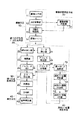
図1に示すように、本発明の第1乃至第3の実施の形態に係るコードイメージ読取装置は、図8を参照して先に説明した従来の読取装置の構成である撮像手段10、誤り訂正符号データ生成手段20、誤り訂正処理手段30、再生手段40に対し、撮像状態判定部51で構成される撮像状態判定手段50と、消失エラー位置判定部61、消失エラー情報付加部62、及び消失エラー情報メモリ部63から構成される消失エラー位置推定手段60とを更に付加したものである。ここで、撮像手段10乃至再生手段40の作用は従来と同様であるため、それらの説明は省略する。
【0031】
よって、以下、上記撮像状態判定手段50及び消失エラー位置推定手段60について説明する。
【0032】
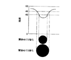
先に説明したように、紙に光学的に記録された所定のブロック配列フォーマットのドットコードの画像データを、画像入力部11で読み込み、A/D変換部12により電気信号に変換するが、本発明の第1乃至第3の実施の形態では、この変換された画像データを、撮像状態判定部51に取り込み、撮像状態を判定する。即ち、撮像状態判定部51は、まず、図2に示すように、撮像画面(フレーム)100を、その1/12のサイズの12個のサブフレーム101に分割する。そして、サブフレーム101毎に輝度の最大値を最大特徴量として抽出し、サブフレーム101毎の撮像状態を判定する。また、全サブフレーム中、即ち1つのフレーム中における輝度の最小値を最小特徴量として抽出する。
【0033】
例えば、本発明の第1乃至第3の実施の形態の場合、輝度を6ビット64階調とした場合の最大特徴量を、各サブフレーム毎に抽出する。図2に示す撮像フレーム100は、撮像状態が均一ではなく、不均一な(シェーディングのある)状態であり、図中フレーム100上方に向かうに従って徐々に暗くなっている状態を表す。サブフレームNo.1(SfNo.1)の場合の最大特徴量は「35」、同様にサブフレームNo.2(SfNo.2)は「30」、というようにサブフレームNo.12(SfNo.12)の「58」まで順次抽出を行う。また、全サブフレームを対象としたフレーム内最小値「3」を抽出する。なお、後述する本発明の第1の実施の形態の場合、これら抽出された各サブフレーム101の最大特徴量とフレーム100の最小特徴量との中間値を、2値化処理部13での2値化のための閾値とする。
【0034】
また、このような撮像状態判定部51の情報に基づいて、消失エラー位置判定部61で、消失エラーがあるかどうかの判断を行う。消失エラーがあると判断すると、消失エラー情報付加部62において、各ドットに対応するデータに消失エラー情報を付加し、その情報を消失エラー情報メモリ部63に記憶する。
【0035】
そして、この消失エラー情報メモリ部63に記憶した情報を使って、エラー訂正部31で訂正を行う。訂正を行った後の工程は、先に図8を参照して説明した従来の工程と同様である。
【0036】
[第1の実施の形態]
以上を共通の基本構成とした、本発明の第1の実施の形態を説明する。
【0037】
消失エラー位置判定部61は、上記共通基本構成で説明した2値化の計算方法によって求められた閾値を使用して、各サブフレーム毎に計算を行い2値化を行う。簡単に説明すると、上記撮像状態判定部51によって、各サブフレーム101内の最大特徴量とフレーム100内の最小特徴量の間を2等分し、閾値とする。例えば、サブフレームNo.1(SfNo.1)においては、

【0038】
なお、この閾値には、予め上限値と下限値が設定してあり、その値を超えて閾値を設定することができないようになっている。本実施の形態の場合、上限値が「48」、下限値が「15」であり、計算結果の閾値が例えば「50」や「6」の場合でも、「48」と「15」に固定されてしまう。本実施の形態では、消失エラー位置判定部61は、上記閾値の計算結果が「48」もしくは「15」に固定されたことを検出し、その情報によって消失エラー位置を検出するようにしている。
【0039】
即ち、撮像フレーム100が許容以上に明るい状態の場合、閾値が「48」に固定される。この状態を図3に示す。本来ならば「49」以上の閾値で2値化されるべきであるが、閾値が「48」で2値化するため、本来よりも黒ドットは細く、白ドットは太い状態で読み取られる。即ち、黒ドットが白ドットと読み間違えられる可能性が高くなる。よって、閾値が「48」と計算されたサブフレーム内の、すべての黒ドットに消失エラーフラグを、消失エラー情報付加部62により付加する。また反対に、撮像フレーム100が許容以上に暗い状態の場合、閾値が「15」に固定される。この状態は、本来ならば「14」以下の閾値で2値化されるべきであるが、閾値が「15」で2値化するため、本来よりも黒ドットは太く、白ドットは細い状態で読み取られる。即ち、白ドットが黒ドットと読み間違えられる可能性が高くなる。よって、消失エラー情報付加部62により、閾値が「15」と算出されたサブフレーム内の、すべての白ドットに消失エラーフラグを付加する。そして、これらの情報を消失エラー情報メモリ部63に記憶する。
【0040】
一方、撮像手段10により読み取られた白ドット,黒ドットの画像データは、誤り訂正符号データ生成手段20により、それぞれデジタルデータである「0」,「1」に変換された後、復調されて8ビット(=1バイト)の情報とされる。
【0041】
ところで、誤り訂正処理手段30のエラー訂正部31では、リードソロモン符号化理論を使用するが、この方法は、対象データをバイト単位で扱うため、バイト単位ごとの消失エラー情報が必要である。よって、消失エラー情報が付加されたビットを含むバイトをバイトエラーとして扱うために、上記消失エラー情報メモリ部63に記憶された消失エラー情報に基づいて、図4の(A)に示すように、消失エラー情報が付加されたビット(ビットエラー102)を含む、上記復調されたバイトデータに対して、消失エラー情報ビット103を付加して、ブロックデータメモリ24に記憶していく。
【0042】
そして、エラー訂正部31は、メモリ書き込み方向とは直交する方向にブロックデータメモリ24から読み出すことによりデインターリーブ処理を行った、バイトエラーを含む一つの誤り訂正符号データ、即ち、図4の(B)に示すように消失エラー情報ビット103が付加された、例えば誤り訂正符号データ長64バイトのデータに対して、リードソロモン符号化理論によりエラー訂正を行う。
【0043】
この訂正後のデータは、再生手段40にて、音声データ用に伸長され、D/A変換されてスピーカから再生される。
【0044】
従って、本第1の実施の形態によれば、コードイメージを再生する場合において、簡単な消失エラー位置推定方法で検査パリティが多くならず、データエラー訂正時に処理時間が比較的短時間で処理できる処理方法を提供し、以って、コードイメージを読み取って確実且つ高速に元のマルチメディアデータを再生できるコードイメージ読取装置を提供することができる。
【0045】
更に、本第1の実施の形態によれば、次のような特有の効果がある。
簡単な検出方法により、消失の可能性のあるビットを検出でき、訂正能力が向上する。また、大幅なハードウェアの変更が生じないので、コードイメージ読取装置のコストアップを抑えることができる。
【0046】
なお、本第1の実施の形態の各構成は、当然、各種の変形、変更が可能である。
例えば、上記エラー訂正方式はリードソロモン符号に限るものではない。また、本実施の形態では、撮像状態の判定を、輝度の情報である閾値を用いて判断するものとしたが、撮像した状態が歪んでいるか否かの状態を判断したり、歪曲情報を用いて判断を行っても勿論かまわない。
【0047】
[第2の実施の形態]
次に、本発明の第2の実施の形態について説明する。
【0048】
上記第1の実施の形態では、図1の撮像状態判定手段50において判定した各サブフレーム(SfNo.1〜SfNo.12)の最大特徴量とフレーム内の最小特徴量とから、予め決められた処理によって閾値を算出したが、本第2の実施の形態では、予め2つの閾値(上閾値と下閾値)を決めて処理を行うものである。
【0049】
例えば、最大特徴量と最小特徴量の間を、2:1:2の割合で分割すると、消失エラー位置判定部61において、サブフレームNo.1(SfNo.1)では、階調値で下閾値が「15」、上閾値が「22」となり、「3」以上「15」以下の濃度を持つデータを黒ドット、「22」以上「35」以下の濃度を持つデータが白ドットと判断される。
【0050】
これに対して、「15」を越えて「22」未満の濃度を有する中濃度データは、消失エラーとして消失エラー情報メモリ部63に記憶される。このとき、消失エラー情報付加部62は、データの濃度に対して確信度の情報を付加することができる。即ち、上閾値と下閾値のほぼ中間値に当たる、「18」に近いデータを一番確信度を低くし、その値から離れるに従って確信度を上げていく。よって、「16」や「21」といった階調のデータが一番確信度が高いことになる。具体的には、「16」と「21」の濃度を有するデータが確信度「3」、「17」と「20」の濃度を有するデータが確信度「2」、「18」と「19」の濃度を有するデータが確信度「1」である。それ以外のデータは、確信度の情報ビットを「0」と記録する。
以上の処理を、全サブフレームに対し行う。
【0051】
一方、撮像手段10により読み取られた白ドット,黒ドットの画像データは、誤り訂正符号データ生成手段20により、それぞれデジタルデータである「0」,「1」に変換された後、復調されてバイトデータとされ、上記第1の実施の形態と同様に並び替えられて、ブロックデータメモリ24に2次元的に再配置される。このとき、上記消失エラー情報メモリ部63に記憶された消失エラー位置情報に基づいて、消失エラーを含んだビットを有していると判別された場合には、当該バイトが消失エラーとして扱われ、その消失エラーを含んだビットに対応する確信度を上記消失エラー情報メモリ部63から読み出して2ビットの確信度情報が付加記憶される。なお、1つのバイトに複数の消失エラーのビットを含んだ場合、ビットに対して確信度が違うことが起こりえる。このようなときには、最も低い確信度を対象のバイトに与えるものとする。
【0052】
そして、エラー訂正部31は、メモリ書き込み方向とは直交する方向にブロックデータメモリ24から読み出すことによりデインターリーブ処理を行った、バイトエラーを含む一つの誤り訂正符号データ、即ち、図4の(C)に示すような各バイト毎に2ビットの確信度情報104が付加された、例えば誤り訂正符号データ長64バイトのデータに対して、リードソロモン符号化理論によりエラー訂正を行う。
【0053】
このエラー訂正部31においては、上記第1の実施の形態同様にリードソロモン符号化理論を使って、符号化された情報を訂正する。このとき、上記消失エラー情報メモリ部63に記憶されている消失エラー位置情報を使ってエラー訂正を行う。1回のエラー訂正処理を行って訂正できなかった場合、確信度の高いバイトデータからエラーフラグを取り除き、即ち消失エラーとしての扱いを取りやめ、再びエラー訂正処理を行う。例えば、濃度が「16」のビットデータを一つ含んでいるバイトデータの場合は、復調前の濃度が「16」のビットを黒ドットとして、また濃度が「22」のビットデータを一つ含んでいるバイトデータの場合は、復調前の濃度が「22」のビットを白ドットとして、復調を行い、再び誤り訂正符号データの訂正を行う。この2回目の訂正処理においても訂正できない場合には、次に確信度の低いデータ、「17」と「21」のデータについてそれぞれ黒ドット、白ドットに置き換えて復調を行い、対象バイトを消失エラー無しとして誤り訂正符号データの訂正を行う。この処理を順次繰り返し、訂正を行う。すべての消失エラーを取りやめて訂正できなかった場合には、エラーとして処理を終了する。
【0054】
訂正後のデータの処理は、上記第1の実施の形態同様に処理を行いスピーカなどから再生する。
【0055】
従って、本第2の実施の形態によれば、コードイメージを再生する場合において、簡単な消失エラー位置推定方法で検査パリティが多くならず、データエラー訂正時に処理時間が比較的短時間で処理できる処理方法を提供し、以って、コードイメージを読み取って確実且つ高速に元のマルチメディアデータを再生できるコードイメージ読取装置を提供することができる。
【0056】
更に、本第2の実施の形態によれば、簡単な構成により、繰り返しエラー訂正が可能なため、より訂正能力を向上することができる。
【0057】
なお、本第2の実施の形態の各構成は、当然、各種の変形、変更が可能である。
即ち、上記撮像装置はCCDに限らず、CMOSセンサなどでもかまわない。また、エラー訂正方式はリードソロモン符号に限っていない。また、閾値を固定としたが、上記第1の実施の形態のように閾値を計算によって求めても勿論かまわない。また、上記確信度情報は2ビット(4段階)としたが、2ビット以上設けて、より詳細に情報を付加してもかまわない。
【0058】
[第3の実施の形態]
次に、本発明の第3の実施の形態について説明する。
【0059】
本第3の実施の形態は、コード内の非データ領域であるパターンドット7を利用し、撮像されたパターンドット7の状態によって、消失エラーフラグを立てるというものである。
【0060】
即ち、閾値が全撮像画像において固定された状態で、パターンドット7の面積に応じた消失エラー位置情報を付加する。撮像エリアが暗い時は、撮像されたパターンドット7が結果的に太くなり、最適な明るさで撮像した場合と比較して、パターンドット7の面積の総計が大きくなる。よって、白ドットが黒ドットと誤認識される可能性が高くなる。反対に、撮像エリアが明るいときは、パターンドット7が結果的に細く撮像される。よって、黒ドットが白ドットと誤認識される可能性が高くなる。このとき、撮像状態判定手段50で、例えばパターンドット7が太いと判断された場合、消失エラー位置推定手段60は、撮像されたブロックの白ドットデータに対して、消失エラー情報を付加する。また反対に、パターンドット7が細いと判断された場合には、撮像されたブロックの黒ドットデータに対して、消失エラー情報を付加する。
【0061】
次に、パターンドット7の面積に対する、消失エラーフラグ付加条件について説明する。
【0062】
1つのブロック2に対してパターンドット7は24個の黒ドットで形成されている。最適な明るさで読み込まれている場合は、1ブロック当たりのパターンドット面積の総計は6.8×10⁻²〔mm2〕程度の面積になる。これより明るい場合は面積の総計が小さくなり、暗い場合には大きくなる。撮像状態が明るい場合において、1ブロック当たりのパターンドットの面積の総計が3.0×10⁻²〔mm2〕以下になれば、明るさの許容を越えたことになり、そのパターンドットを含む対象となるブロック2の黒ドットすべてに消失エラーフラグを付加する。反対に、撮像状態が暗い場合において、1ブロック当たりのパターンドットの面積の総計が1.2×10⁻¹〔mm2〕以上になれば、暗さの許容を越えたことになり、そのパターンドットを含む対象となるブロック2の白ドットすべてに消失エラーフラグを付加する。
【0063】
消失エラー情報を有したビットのエラー訂正方法、及びそれ以降の処理については、前述の第1の実施の形態と同様であるため、説明を省略する。
【0064】
従って、本第3の実施の形態によれば、コードイメージを再生する場合において、簡単な消失エラー位置推定方法で検査パリティが多くならず、データエラー訂正時に処理時間が比較的短時間で処理できる処理方法を提供し、以って、コードイメージを読み取って確実且つ高速に元のマルチメディアデータを再生できるコードイメージ読取装置を提供することができる。
【0065】
更に、本第3の実施の形態によれば、簡単な構成により、エラー訂正能力を向上することができるという効果を奏する。
【0066】
なお、本第3の実施の形態の各構成は、当然、各種の変形、変更が可能である。
例えば、撮像エリアが暗い時、撮像されたパターンドット7が結果的に太くなり、白ドットが黒ドットと誤認識される可能性が高くなったが、読取装置をコードから浮いた状態で撮像した場合、即ちピントがぼけた状態でも同様な現象が生じるので、この状態におけるドットの太り具合を検出して、太いときに消失エラー情報を付加しても勿論かまわない。
【0067】
また、消失エラーフラグを立てるための情報を、非データ領域であるパターンドット7を利用したが、ブロック2の四隅に配置されている非データ領域のマーカ5の面積に応じて消失エラー情報を付加してもかまわない。
【0068】
また、閾値は、上記第1の実施の形態同様、各サブフレーム毎に算出し、2値化を行っても勿論かまわない。
【0069】
[第4の実施の形態]
次に、本発明の第4の実施の形態について説明する。
【0070】
上記音声データ等を光学的に読み取り可能なコードイメージとして記録された記録媒体から上記コードイメージを読み取る際、その読み取り速度が一定でなくても、ある速度以下のスキャン速度で読み取れば、データを読み取ることができる。この場合、複数の撮像フレームにわたって同じブロックが数回読み込まれる場合がある。本第4の実施の形態はこの特徴を利用し、消失エラー位置情報を付加することを特徴としたものである。即ち、複数にまたがる撮像フレームに、同一のブロックアドレスのデータが撮像された場合、同じブロックアドレスのデータを比較して、データ内容が違っていれば、そのデータを消失エラーとして訂正を行うものである。
【0071】
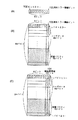
図5の(A)は、アドレスA,B,C,D,E,F,G,H,…を有するコードを、アドレスG,H方向からアドレスA,B方向へと読取装置をスキャニングさせ撮像している様子を示している。そして、図5の(B)には、ある撮像タイミングにおける撮像状態(フレームm)と、そのフレームmの次の撮像タイミングにおける撮像状態(フレームm+1)とを並べて示している。フレームmでは、ブロックアドレスC,D,E,F,G,Hを有するブロックが撮像されており、フレームm+1では、ブロックアドレスA,B,C,D,E,Fを有するブロックが撮像されている。
【0072】
図6は、本第4の実施の形態に係るコードイメージ読取装置の構成を示す図である。なお同図において、上記第1乃至第3の実施の形態と同様の構成については、図1と同じ参照番号を付してあり、よってそれらの詳細説明は省略する。
【0073】
本実施の形態に係るコードイメージ読取装置においては、アドレス検出部25でブロックアドレスが取得されると、ブロックデータと共にそのアドレス情報もブロックデータメモリ24に一時記憶される。そして、フレームmとフレームm+1で読み込まれたアドレス情報の中で、重複しているアドレスに対するデータ(C,D,E,F)の比較を、同一アドレス比較部70で行う。同じブロックアドレスC,D,E,Fのデータに対して比較を行った結果、フレームmとフレームm+1で違う場合には、先に読まれたフレームmのデータに対して消失エラー位置推定手段60によって消失エラー位置情報を付加する。その後、誤り訂正符号データ生成手段20で、復調及び並べ替えを行い、誤り訂正処理手段30で、消失エラー位置情報を参照してエラー訂正処理を行い復元し、再生手段40によってデータを再生する。
【0074】
従って、本発明の第4の実施の形態によれば、コードイメージを再生する場合において、簡単な消失エラー位置推定方法で検査パリティが多くならず、データエラー訂正時に処理時間が比較的短時間で処理できる処理方法を提供し、以って、コードイメージを読み取って確実且つ高速に元のマルチメディアデータを再生できるコードイメージ読取装置を提供することができる。
【0075】
更に、本第4の実施の形態によれば、複数回読まれたデータに対して、比較を行いながら消失エラーを設定できるため、より確実な消失エラー情報が付加できる。
【0076】
なお、この第4の実施の形態の各構成は、当然、各種の変形、変更が可能である。
【0077】
例えば、それぞれの実施の形態を複数組み合わせて、より確実な消失エラー情報を付加しても構わない。また、それぞれの実施の形態に対する確からしさを付加し、一番確かな情報を一つ、または複数採用しても構わない。
【0078】
以上実施の形態に基づいて本発明を説明したが、本発明は上述した実施の形態に限定されるものではなく、本発明の要旨の範囲内で種々の変形や応用が可能である。ここで、本発明の要旨をまとめると以下のようになる。
【0079】
(1) 記録すべきデータと検査パリティとからなる誤り訂正符号データが光学的に読取可能なコードイメージとして印刷記録された記録媒体から、上記コードイメージを光学的に読み取るコードイメージ読取装置において、
上記コードイメージを撮像する撮像手段と、
上記撮像手段で撮像されたコードイメージを処理して上記誤り訂正符号データを生成する誤り訂正符号データ生成手段と、
上記撮像手段で撮像されたコードイメージの撮像状態を判定する撮像状態判定手段と、
上記撮像状態判定手段で判定されたコードイメージの撮像状態に基づいて、上記誤り訂正符号データ生成手段で生成される誤り訂正符号データの消失エラー位置を推定する消失エラー位置推定手段と、
上記消失エラー位置推定手段で推定された消失エラー位置に基づいて、上記誤り訂正符号データ生成手段で生成された誤り訂正符号データの誤り訂正処理を行う誤り訂正処理手段と、
を具備することを特徴とするコードイメージ読取装置。
【0080】
この発明に関する実施の形態は、第1の実施の形態が該当する。この(1)の記載中の光学的に読取可能なコードイメージは、この第1の実施の形態では、ドットコードが該当する。また、撮像手段は、この実施の形態では画像入力部11が該当する。
【0081】
即ち、撮像手段で、紙に印刷記録された誤り訂正符号データである、ドットコードを撮像して電気信号に変換する。変換されたデータは、2値化処理を行い「0」と「1」のデータ列に変換し、誤り訂正符号データ生成手段において誤り訂正符号データを生成する。撮像手段で読み取られた画像の撮像状態を、撮像状態判定手段で判定する。撮像状態が判断された結果に応じて、消失エラー位置推定手段で誤り訂正符号データに消失エラー位置情報を付加する。訂正処理手段で、消失エラー位置情報に基づいて誤り訂正符号データを訂正する。
【0082】
従って、ドットコード内のデータに、新たにエラー訂正符号を付加せず消失エラー位置情報を検出することができるため、ドットコードの面積が小さくて済み、その分多くの情報を記録することができる。
【0083】
(2) 上記撮像状態判定手段は、上記撮像手段で撮像された撮像画面から輝度に関する情報を抽出して上記撮像されたコードイメージの撮像状態を判定し、上記消失エラー位置推定手段は、この抽出された輝度に関する情報に基づいて、上記消失エラー位置を推定することを特徴とする(1)に記載のコードイメージ読取装置。
【0084】
この発明に関する実施の形態は、第1の実施の形態が該当する。
【0085】
即ち、上記撮像状態判定手段において判断された、撮像された画像の輝度の結果に応じて、消失エラー位置推定手段で誤り訂正符号データに消失エラー位置情報を付加する。訂正処理手段で、消失エラー位置情報に基づいて誤り訂正符号データを訂正する。
【0086】
従って、上記(1)の効果に加え、輝度に応じて消失エラー位置情報を推定するため、各撮像フレーム毎に最適な撮像状態が判断でき、不安定な撮像画像状態でも、より確実な消失エラー位置を推定できるという効果を奏する。
【0087】
(3) 上記撮像状態判定手段は、上記撮像手段で撮像された撮像画面を複数に分割して形成された各領域毎に上記輝度に関する情報を抽出して、上記撮像されたコードイメージの撮像状態を判定するように構成され、
上記消失エラー位置推定手段は、この各領域毎に抽出された輝度に関する情報に基づいて、この各領域毎に上記消失エラー位置を推定することを特徴とする(2)に記載のコードイメージ読取装置。
【0088】
この発明に関する実施の形態は、第1の実施の形態が該当する。
【0089】
即ち、上記撮像状態判定手段において、撮像された画像を複数の領域に分割し、その領域ごとの輝度を抽出する。その輝度の情報から撮像状態を判断し、その結果に応じて、消失エラー位置推定手段で誤り訂正符号データに消失エラー位置情報を付加する。訂正処理手段で、消失エラー位置情報に基づいて誤り訂正符号データを訂正する。
【0090】
従って、上記(2)の効果に加え、一撮像画像中の複数の領域で、個々に最適な撮像状態が判断できるため、一つの撮像画像中に輝度のばらつきが生じても、適切な消失エラー位置情報が推定できるという効果を奏する。
【0091】
(4) 上記コードイメージが複数個のブロックより構成され、
上記ブロックのそれぞれが、上記誤り訂正符号データに応じて形成されたデータ領域と、当該ブロックを定義するためのマーカ領域と、を所定の位置関係に従って配置したものであるとき、
上記撮像状態判定手段は、上記ブロック毎に上記輝度に関する情報を抽出して、上記撮像されたコードイメージの撮像状態を判定するように構成され、
上記消失エラー位置推定手段は、この各ブロック毎に抽出された輝度に関する情報に基づいて、この各ブロック毎に上記消失エラー位置を推定することを特徴とする請求項2に記載のコードイメージ読取装置。
【0092】
この発明に関する実施の形態は、第3又は第4の実施の形態が該当する。
【0093】
即ち、上記撮像状態判定手段において、撮像された画像中のコードイメージ内の複数のブロックごとに輝度を抽出する。その輝度の情報から撮像状態を判断し、その結果に応じて、消失エラー位置推定手段で誤り訂正符号データに消失エラー位置情報を付加する。訂正処理手段で、消失エラー位置情報に基づいて誤り訂正符号データを訂正する。
【0094】
従って、上記(2)の効果に加え、ブロック毎の輝度情報よりより確実な消失エラー位置の情報をブロック毎に推定できるため、本来正しく読まれているブロックの情報まで、無駄に消失エラー位置情報を付加することがないという効果を奏する。
【0095】
(5) 上記コードイメージが、高濃度印刷領域と、無印刷領域を含む低濃度印刷領域の2つの相対的に濃度の異なる印刷領域を上記誤り訂正符号データに係る1又は0の各ビットデータに応じて配置した部分を含んで構成されており、
上記撮像状態判定手段は、上記抽出された輝度に関する情報に基づいて、上記撮像されたコードイメージの撮像状態が暗状態及び明状態のいずれの状態であったかを判定する手段を含んでおり、
上記消失エラー位置推定手段は、上記撮像状態判定手段が、上記撮像されたコードイメージの撮像状態を暗状態と判定したとき、上記低濃度印刷領域に対応するビットデータに対して消失エラーフラグを立て、また、上記撮像状態判定手段が、上記撮像されたコードイメージの撮像状態を明状態と判定したとき、上記高濃度印刷領域に対応するビットデータに対して消失エラーフラグを立てるように構成されたことを特徴とする(2)に記載のコードイメージ読取装置。
【0096】
この発明に関する実施の形態は、第1の実施の形態が該当する。この(5)の記載中の高濃度印字領域は、この実施の形態では黒ドットが該当する。また、無印刷領域を含む低濃度印刷領域は、この実施の形態では白ドットが該当する。
【0097】
即ち、上記撮像状態判定手段において、撮像された画像に対し、暗い場合は暗状態と判断し、明るい場合は明状態と判断する。消失エラー位置推定手段で、撮像状態判断手段の結果が暗状態のときは、撮像された画像中のすべての白ドットに対応する誤り訂正符号データに消失エラー位置情報を付加する。反対に撮像状態判断手段の結果が明状態のときは、撮像された画像中のすべての黒ドットに対応する誤り訂正符号データに消失エラー位置情報を付加する。訂正処理手段で、消失エラー位置情報に基づいて誤り訂正符号データを訂正する。
【0098】
従って、上記(2)の効果に加え、黒ドット、もしくは白ドットのどちらか一方のみに消失エラー位置情報が付加されるため、間違った消失エラー位置情報の数が減り、より訂正能力が向上するという効果を奏する。
【0099】
(6) 上記コードイメージが、高濃度印刷領域と、無印刷領域を含む低濃度印刷領域の2つの相対的に濃度の異なる印刷領域を上記誤り訂正符号データに係る1又は0の各ビットデータに応じて配置した部分を含んで構成されており、
上記撮像状態判定手段は、上記抽出された輝度に関する情報に基づいて、上記撮像されたコードイメージから、上記高濃度印刷領域及び低濃度印刷領域の何れにも該当し得ると判定される、所定の中間の濃度を有した中濃度印刷領域の検出を行う中濃度印刷領域検出手段を含んでおり、
上記消失エラー位置推定手段は、上記中濃度印刷領域検出手段が検出した所定の中間の濃度を有した中濃度印刷領域に対応する、上記誤り訂正符号データ生成手段で生成された誤り訂正符号データ中のビットデータに対して消失エラーフラグを立てるように構成されたことを特徴とする(2)に記載のコードイメージ読取装置。
【0100】
この発明に関する実施の形態は、第2の実施の形態が該当する。
【0101】
即ち、上記撮像状態判定手段において、撮像された画像中の各々の印刷領域に対し、中間濃度であるという判断がなされた場合、消失エラー位置推定手段で、中間濃度に対応するドットに対して、消失エラー位置情報を付加する。訂正処理手段で、消失エラー位置情報に基づいて誤り訂正符号データを訂正する。
【0102】
従って、上記(2)の効果に加え、黒ドット、白ドットに関わらず、撮像状態の悪いドットを簡単に検出できるため、より誤り訂正の精度が向上するという効果を奏する。
【0103】
(7) 上記消失エラー位置推定手段は、上記中濃度印刷領域検出手段が検出した所定の中間の濃度を有した中濃度印刷領域に対応する上記ビットデータに対して、更に、当該ビットデータが上記高濃度印刷領域及び低濃度印刷領域の何れの領域に対応するビットデータとなるべきかの程度を示す確信度に関する情報を、当該検出された中間の濃度のレベルに応じて付加する確信度情報付加手段を含むことを特徴とする(6)に記載のコードイメージ読取装置。
【0104】
この発明に関する実施の形態は、第2の実施の形態が該当する。
【0105】
即ち、上記撮像状態判定手段において、撮像された画像中の各々の印刷領域に対し、中間濃度であるという判断がなされた場合、高濃度または低濃度のよりどちらに近いのかという確信度の情報もあわせて付加する。消失エラー位置推定手段で、中間濃度に対応するドットに対して、消失エラー位置情報を付加する。訂正処理手段で、消失エラー位置情報に基づいて誤り訂正符号データを訂正する。
【0106】
従って、上記(6)の効果に加え、黒ドット、もしくは白ドットのどちらか一方のみに消失エラー位置情報が付加され、且つ各々の消失エラー位置情報に確信度の情報が付加されているため、状況に応じて消失エラー位置を選択し、訂正ができるという効果を奏する。
【0107】
(8) 上記誤り訂正処理手段は、上記消失エラー位置に基づいて上記誤り訂正符号データの誤り訂正処理を行う際、一の誤り訂正符号データ中のビットデータに対して上記確信度に関する情報が複数個付加されているとき、最初に、当該確信度の高い情報が付加されているビットデータを正しいビットデータとみなして誤り訂正処理を行うように構成されたことを特徴とする(7)に記載のコードイメージ読取装置。
【0108】
この発明に関する実施の形態は、第2の実施の形態が該当する。
【0109】
即ち、上記訂正処理手段で、エラー処理能力を超えた数の消失エラー情報がある場合、消失エラーデータである中間濃度と判断されたドットの中から最も確信度の高いデータより、消失エラー情報を削除し再度訂正を行う。このとき再びエラー訂正能力を超えたエラー数がある場合には、再度消失エラーデータである中間濃度と判断された残りのドットの中から最も確信度の高いデータより、消失エラー情報を削除し再度訂正を行う。これをエラー訂正可能消失エラー数になるまで繰り返し行う。
【0110】
従って、上記(7)の効果に加え、不確かな消失エラー位置情報を順次、確からしさの優先度の高いデータを、正しいデータとして扱うため、エラー数が多いことが原因による訂正不可の可能性が低くなるという効果を奏する。
【0111】
(9) 上記輝度に関する情報は、上記撮像手段で撮像されたコードイメージの2値化処理に必要とされる閾値に係る情報であることを特徴とする(2)乃至(8)の何れか一に記載のコードイメージ読取装置。
【0112】
この発明に関する実施の形態は、第1の実施の形態が該当する。
【0113】
即ち、上記撮像状態判定手段において、撮像された画像の輝度に関する情報として、閾値に関する情報を利用する。
【0114】
従って、上記(2)乃至(8)の何れか一の効果に加え、輝度に関する情報として閾値を利用しているため、撮像状態の判定が簡単且つ正確に行えるという効果を奏する。
【0115】
(10) 上記コードイメージが、上記誤り訂正符号データに応じて形成されたデータ領域と、上記誤り訂正符号データに依存することなく形成された所定の非データ領域と、から構成されるものであるとき、
上記撮像状態判定手段は、上記撮像手段で撮像された撮像画面から上記非データ領域における情報を抽出して上記撮像されたコードイメージの撮像状態を判定し、
上記消失エラー位置推定手段は、この抽出された非データ領域における情報に基づいて、上記消失エラー位置を推定することを特徴とする(1)に記載のコードイメージ読取装置。
【0116】
この発明に関する実施の形態は、第3の実施の形態が該当する。この(10)の記載中の非データ領域とは、この実施の形態ではパターンドットが該当する。
【0117】
即ち、上記撮像状態判定手段で、パターンドットの面積を測定する。
【0118】
従って、上記(1)の効果に加え、処理速度が高速にできるため、簡単なロジックで構成することができるという効果を奏する。
【0119】
(11) 上記非データ領域における情報は、輝度に関する情報を含むことを特徴とする(10)に記載のコードイメージ読取装置。
【0120】
この発明に関する実施の形態は、第2の実施の形態が該当する。
【0121】
即ち、上記撮像状態判定手段で、データ禁止領域の輝度を測定する。輝度値が所定の規定値の範囲以外であれば、その撮像された画像中のデータに消失エラー位置情報を付加する。
【0122】
従って、上記(10)の効果に加え、撮像状態の判定がしやすいという効果を奏する。
【0123】
(12) 上記コードイメージが複数個のブロックより構成され、
上記ブロックのそれぞれが、上記誤り訂正符号データに応じて形成されたデータ領域と、当該ブロックを定義するためのマーカ領域と、当該ブロックのアドレス示すブロックアドレスデータ領域と、を所定の位置関係に従って配置したものであるとき、
上記撮像状態判定手段は、上記撮像手段で撮像された複数の撮像画面から同一のブロックアドレスを有するブロックを複数個検出し、当該検出した複数個のブロックに含まれる各対応する誤り訂正符号データを比較して異なるビットデータを抽出するように構成され、
上記消失エラー位置推定手段は、この抽出された異なるビットデータを上記消失エラー位置として推定することを特徴とする(1)に記載のコードイメージ読取装置。
【0124】
この発明に関する実施の形態は、第4の実施の形態が該当する。
【0125】
即ち、撮像手段で、ドットコードを撮像して、その画像データをA/D変換により電気信号に変換する。撮像状態判定手段で、撮像されたコードからブロックを検出し、アドレスが取得される。消失エラー位置推定手段は、撮像画像間で、同一のブロックアドレスが存在する場合、画像間の誤り訂正符号データを比較し、相違しているデータに対して消失エラーフラグ位置情報を付加する。
【0126】
従って、上記(1)の効果に加え、複数回読み込まれたアドレスのブロック内データを比較するため、より確実な消失エラーデータのみを抽出することができるという効果を奏する。
【0127】
【発明の効果】
以上詳述したように、本発明によれば、コードイメージを再生する場合において、簡単な消失エラー位置推定方法で検査パリティが多くならず、データエラー訂正時に処理時間が比較的短時間で処理できる処理方法を提供することができ、よって、コードイメージを読み取って確実且つ高速に元のマルチメディアデータを再生できるコードイメージ読取装置を提供することができる。
【図面の簡単な説明】
【図1】本発明の第1乃至第3の実施の形態に係るコードイメージ読取装置のブロック構成図である。
【図2】図1中の撮像状態判定部におけるフレームの分割と特徴量の抽出を説明するための図である。
【図3】閾値と2値化の関係を説明するための図である。
【図4】(A)は消失エラー情報が付加されたビットを含む復調されたバイトデータを示す図、(B)は第1の実施の形態におけるバイトエラーを含む一つの誤り訂正符号データを示す図であり、(C)は第2の実施の形態におけるバイトエラーを含む一つの誤り訂正符号データを示す図である。
【図5】(A)はコードの走査方向を示す図であり、(B)は(A)のように走査した場合に得られる連続する2つの撮像状態の様子を示す図である。
【図6】本発明の第4の実施の形態に係るコードイメージ読取装置のブロック構成図である。
【図7】光学的に読み取り可能なコードイメージとしてのドットコードの物理フォーマット構成を示した図である。
【図8】従来のコードイメージ読取装置のブロック構成図である。
【図9】(A)はアドレス順に並び替えられたブロックアドレスの状態を示す図、(B)はブロックデータメモリに2次元的に再配置されたブロックアドレスの状態を示す図であり、(C)は一つの誤り訂正符号データを示す図である。
【図10】従来の誤り位置検出(消失エラー位置の検出)方法を説明するための図である。
【符号の説明】
1 ドットコード
2 ブロック
3 データエリア
4 データドット
5 マーカ
6 ブロックアドレスパターン
7 パターンドット
10 撮像手段
11 画像入力部
13 2値化処理部
20 訂正符号データ生成手段
24 ブロックデータメモリ
30 誤り訂正処理手段
31 エラー訂正部
40 再生手段
50 撮像状態判定手段
51 撮像状態判定部
60 消失エラー位置推定手段
61 消失エラー位置判定部
62 消失エラー情報付加部
63 消失エラー情報メモリ部
70 同一アドレス比較部
100 撮像フレーム
101 サブフレーム
102 ビットエラー
103 消失エラー情報ビット
104 確信度情報[0001]
BACKGROUND OF THE INVENTION
The present invention reproduces a code image in which multimedia data including audio data, video data, and text data is recorded as an optically readable code image on a sheet-like recording medium such as paper or film. The present invention relates to a code image reading apparatus.
[0002]
[Prior art]
First, recording audio data as an optically readable code image will be described with reference to FIG.
[0003]
FIG. 7 is a diagram showing a format configuration of the
[0004]
That is, a plurality of
[0005]
Thus, according to this dot code, even if the entire size of the dot code is larger than the imaging field of view of the reading means, the reading means is manually scanned on the dot code and sequentially picked up while dividing the area. Data can be read. In other words, even if the dot code cannot be imaged in one shot, if each address given to the block is read together with the block data, the data of each block is collected by the address and the original data Can be reconstructed.
[0006]
Therefore, the dot code can be practically printed and recorded on an audio paper surface that could not be realized by a conventional one-dimensional or two-dimensional barcode, and is expected in the future.
[0007]
Next, a reading method of a reading device as reading means for reading such a dot code will be described with reference to the block diagram of FIG.
[0008]
The conventional reading apparatus includes an
[0009]
In the image pickup means 10, the dot code shown in FIG. 7 is read by an
[0010]
Next, in the error correction code data generation means 20, the
[0011]
The data is 4-5 modulated at the time of recording. This is because if the
[0012]
Address information is recorded in each
[0013]
FIG. 9A shows the state of the rearranged block addresses. On the other hand, the rearranged data is rearranged two-dimensionally in the
[0014]
In the error correction processing means 30, the
[0015]
In the reproducing means 40, since the audio data is compressed at the time of recording, the decompressing unit 41 decompresses the data obtained by the correction. The decompressed data is subjected to D / A conversion processing by the D /
[0016]
However, when paper is used as the recording medium, the reading state is unstable because the recording state is very unstable. Therefore, when reading the code image, the code image is not always read to a correct value, and erroneous data may be read. It is necessary to correct the data having the reading error to a correct value. Therefore, the
[0017]
Hereinafter, an error correction method in the
[0018]
In order to perform this error correction, Reed-Solomon coding theory is generally used in many cases. The correction capability of the correction method using the erasure error position of the Reed-Solomon code is such that the number of error data whose error position is unknown is a, the number of error data whose error position is known is b, and the Hamming distance is d.
d> 2 · a + b (1)
Can be corrected as long as Therefore, the correction capability is improved by determining the error position, that is, detecting the erasure error position.
[0019]
For example, consider a case in which a check parity of 16 bytes is added to 48 bytes of user data, resulting in a total error correction code data length of 64 bytes. The error correction capability in a state where the normal error position is unknown can correct up to 8 bytes of 64 bytes. However, when all the error positions are known, the correction capability can be improved up to 16 bytes. Therefore, how to detect the position of data in which an error has occurred is an important issue for improving the correction capability.
[0020]
Conventionally, as an error position detection (erasure error position detection) method, for example, a product code as shown in FIG. 10 is added to detect the position of data causing an error, and the data causing the error is processed as an erasure error. A correction method is used. That is, deinterleaving is performed by arranging data in a matrix. As a result, correction is performed using double check parity in the row and column directions added in advance during recording. At the time of error correction, for example, it is assumed that correction is first performed for each line, and
[0021]
Further, as a method for generating erasure information from block dropping, a method is known in which a synchronized range including consecutive error locations is treated as erasure as described in Japanese Patent Publication No. 7-66630.
[0022]
[Problems to be solved by the invention]
However, this type of data error correction processing method has the following problems.
[0023]
That is, in order to perform error correction, a check parity must be added. However, when the product code is used, more error check codes are required for the same user data than in the case where the check parity is simply added, and there is a problem that the entire data amount is increased. As a result, there is a problem that the area of the code image increases and the space efficiency is deteriorated. In addition, when an uncorrectable code occurs, the correction processing is performed twice for the rows and columns of the user data array, and there is a problem that the processing time is doubled. Moreover, in the method described in Japanese Patent Publication No. 7-66630, a synchronized range including consecutive error portions is treated as erasure, but in this method, even correct data is treated as an erasure error. There is a problem that useless correction processing is included.
[0024]
The present invention has been made in view of the above points. When a code image is reproduced, the check parity does not increase with a simple erasure error position estimation method, and the processing time is relatively short when correcting a data error. It is an object of the present invention to provide a processing method capable of processing, and thus to provide a code image reading device capable of reading a code image and reproducing the original multimedia data reliably and at high speed.
[0025]
[Means for Solving the Problems]
In order to achieve the above object, a code image reading apparatus according to the present invention comprises:
A code image reader that optically reads the code image from a recording medium on which error correction code data composed of data to be recorded and check parity is printed and recorded as an optically readable code image,
Imaging means for imaging the code image;
Error correction code data generation means for processing the code image captured by the imaging means to generate the error correction code data;
An imaging state determination unit that determines an imaging state of a code image captured by the imaging unit;
Erasure error position estimation means for estimating the erasure error position of the error correction code data generated by the error correction code data generation means based on the imaging state of the code image determined by the imaging state determination means;
Based on the erasure error position estimated by the erasure error position estimation means, error correction processing means for performing error correction processing of the error correction code data generated by the error correction code data generation means,
Equipped withAnd
When the code image is composed of a plurality of blocks including data obtained by dividing the error correction code data,
The imaging state determination unit detects the same block from a plurality of imaging screens captured for each frame by the imaging unit, compares the data included in the detected plurality of the same blocks, and compares the data Is configured to extract different blocks,
The erasure error position estimation means is configured to estimate a block having different data extracted by the imaging state determination means as the erasure error position.It is characterized by that.
[0026]
That is, according to the code image reading apparatus of the present invention, the imaging unit picks up the dot code, which is error correction code data printed and recorded on paper, converts it into an electrical signal, and converts the converted data into 2 A value conversion process is performed to convert the data into “0” and “1” data strings, and error correction code data generation means generates error correction code data. In addition, the imaging state of the image read by the imaging unit is determined by the imaging state determination unit, and the erasure error position estimation unit determines the erasure error in the error correction code data according to the result of the determination of the imaging state. Add location information. Then, the correction processing means corrects the error correction code data based on the erasure error position information.
[0027]
Therefore, since it is possible to detect the erasure error position information without newly adding an error correction code to the data in the dot code, the area of the dot code can be reduced, and a larger amount of information can be recorded accordingly. .
[0028]
DETAILED DESCRIPTION OF THE INVENTION
Hereinafter, first to fourth embodiments of the present invention will be described with reference to the drawings.
[0029]
First, a basic configuration common to the first to third embodiments among the first to fourth embodiments will be described with reference to the block diagram of FIG.
[0030]
As shown in FIG. 1, the code image reading apparatus according to the first to third embodiments of the present invention includes an
[0031]
Therefore, the imaging state determination unit 50 and the erasure error
[0032]
As described above, dot code image data in a predetermined block arrangement format optically recorded on paper is read by the
[0033]
For example, in the case of the first to third embodiments of the present invention, the maximum feature amount when the luminance is 6 bits and 64 gradations is extracted for each subframe. An imaging frame 100 illustrated in FIG. 2 represents a state in which the imaging state is not uniform but non-uniform (with shading) and gradually darkens toward the top of the frame 100 in the drawing. In the case of subframe No. 1 (SfNo.1), the maximum feature amount is “35”, and similarly, subframe No.2 (SfNo.2) is “30”, so that subframe No.12 (SfNo.12) ) Until “58”. Also, the in-frame minimum value “3” for all subframes is extracted. In the case of the first embodiment of the present invention described later, an intermediate value between the extracted maximum feature amount of each
[0034]
Further, based on the information of the imaging
[0035]
Then, the
[0036]
[First Embodiment]
The first embodiment of the present invention will be described with the above as a common basic configuration.
[0037]
The erasure error
[0038]
Note that an upper limit value and a lower limit value are set in advance for the threshold value, and the threshold value cannot be set beyond that value. In the case of the present embodiment, even when the upper limit value is “48” and the lower limit value is “15”, and the threshold value of the calculation result is, for example, “50” or “6”, it is fixed to “48” and “15”. End up. In the present embodiment, the erasure error
[0039]
That is, the threshold value is fixed to “48” when the imaging frame 100 is brighter than allowable. This state is shown in FIG. Originally, binarization should be performed with a threshold value of “49” or more, but since the binarization is performed with a threshold value of “48”, the black dots are read thinner than the original and the white dots are read thicker. That is, there is a high possibility that black dots will be mistaken for reading as white dots. Therefore, the erasure error
[0040]
On the other hand, the image data of white dots and black dots read by the image pickup means 10 is converted into digital data “0” and “1” by the error correction code data generation means 20, respectively, and then demodulated to 8 It is information of bits (= 1 byte).
[0041]
By the way, the
[0042]
Then, the
[0043]
The corrected data is decompressed for audio data by the reproducing
[0044]
Therefore, according to the first embodiment, when a code image is reproduced, the check parity does not increase with a simple erasure error position estimation method, and the processing time can be processed in a relatively short time when correcting a data error. By providing a processing method, it is possible to provide a code image reader capable of reading a code image and reproducing the original multimedia data reliably and at high speed.
[0045]
Furthermore, according to the first embodiment, there are the following specific effects.
A simple detection method can detect bits that may be lost, improving the correction capability. In addition, since no significant hardware change occurs, the cost increase of the code image reading apparatus can be suppressed.
[0046]
Of course, each configuration of the first embodiment can be variously modified and changed.
For example, the error correction method is not limited to the Reed-Solomon code. In the present embodiment, the determination of the imaging state is determined using a threshold value that is luminance information. However, it is determined whether the captured state is distorted or distortion information is used. Of course, it doesn't matter if you make a decision.
[0047]
[Second Embodiment]
Next, a second embodiment of the present invention will be described.
[0048]
In the first embodiment, it is determined in advance from the maximum feature amount of each subframe (SfNo. 1 to SfNo. 12) determined by the imaging state determination unit 50 of FIG. 1 and the minimum feature amount in the frame. Although the threshold value is calculated by processing, in the second embodiment, processing is performed by determining two threshold values (upper threshold value and lower threshold value) in advance.
[0049]
For example, when the ratio between the maximum feature amount and the minimum feature amount is divided at a ratio of 2: 1: 2, the erasure error
[0050]
On the other hand, medium density data having a density exceeding “15” and less than “22” is stored in the erasure error
The above processing is performed for all subframes.
[0051]
On the other hand, the image data of white dots and black dots read by the image pickup means 10 is converted into digital data “0” and “1” by the error correction code data generation means 20, respectively, and then demodulated and converted into bytes. Data is rearranged in the same manner as in the first embodiment, and rearranged two-dimensionally in the
[0052]
Then, the
[0053]
The
[0054]
The corrected data is processed as in the first embodiment and reproduced from a speaker or the like.
[0055]
Therefore, according to the second embodiment, when a code image is reproduced, the check parity does not increase by a simple erasure error position estimation method, and the processing time can be processed in a relatively short time when correcting a data error. By providing a processing method, it is possible to provide a code image reader capable of reading a code image and reproducing the original multimedia data reliably and at high speed.
[0056]
Furthermore, according to the second embodiment, since it is possible to perform error correction repeatedly with a simple configuration, the correction capability can be further improved.
[0057]
Of course, each configuration of the second embodiment can be variously modified and changed.
That is, the imaging device is not limited to a CCD, and may be a CMOS sensor or the like. Further, the error correction method is not limited to the Reed-Solomon code. Although the threshold value is fixed, it is of course possible to obtain the threshold value by calculation as in the first embodiment. The certainty information is 2 bits (4 stages), but more than 2 bits may be provided to add more detailed information.
[0058]
[Third Embodiment]
Next, a third embodiment of the present invention will be described.
[0059]
In the third embodiment, a
[0060]
That is, erasure error position information corresponding to the area of the pattern dot 7 is added in a state where the threshold value is fixed in all captured images. When the imaging area is dark, the imaged pattern dot 7 becomes thicker as a result, and the total area of the pattern dot 7 becomes larger than in the case of imaging with the optimum brightness. Therefore, there is a high possibility that white dots are erroneously recognized as black dots. On the contrary, when the imaging area is bright, the
[0061]
Next, the condition for adding the disappearance error flag to the area of the pattern dot 7 will be described.
[0062]
The pattern dot 7 is formed of 24 black dots for one
[0063]
An error correction method for bits having erasure error information and subsequent processing are the same as those in the first embodiment described above, and thus description thereof is omitted.
[0064]
Therefore, according to the third embodiment, when a code image is reproduced, check parity is not increased by a simple erasure error position estimation method, and processing time can be processed in a relatively short time when correcting a data error. By providing a processing method, it is possible to provide a code image reader capable of reading a code image and reproducing the original multimedia data reliably and at high speed.
[0065]
Furthermore, according to the third embodiment, the error correction capability can be improved with a simple configuration.
[0066]
Of course, each configuration of the third embodiment can be variously modified and changed.
For example, when the imaging area is dark, the captured pattern dot 7 becomes thicker as a result, and there is a high possibility that the white dot is erroneously recognized as a black dot. In other words, the same phenomenon occurs even when the image is out of focus, so it is of course possible to detect the dot thickness in this state and add erasure error information when the dot is thick.
[0067]
In addition, the information for setting the erasure error flag is obtained by using the pattern dot 7 which is a non-data area. It doesn't matter.
[0068]
Further, as in the first embodiment, the threshold value may be calculated for each subframe and binarized as a matter of course.
[0069]
[Fourth Embodiment]
Next, a fourth embodiment of the present invention will be described.
[0070]
When reading the code image from a recording medium in which the audio data or the like is recorded as an optically readable code image, even if the reading speed is not constant, the data is read if it is read at a scanning speed below a certain speed. be able to. In this case, the same block may be read several times over a plurality of imaging frames. The fourth embodiment uses this feature and adds erasure error position information. In other words, when data of the same block address is captured in a plurality of imaging frames, the data of the same block address is compared, and if the data contents are different, the data is corrected as an erasure error. is there.
[0071]
FIG. 5A shows an image obtained by scanning a reader having addresses A, B, C, D, E, F, G, H,... From the addresses G and H directions to the addresses A and B directions. It shows how they are doing. In FIG. 5B, the imaging state (frame m) at a certain imaging timing and the imaging state (frame m + 1) at the next imaging timing of the frame m are shown side by side. In frame m, blocks having block addresses C, D, E, F, G, and H are imaged. In frame m + 1, blocks having block addresses A, B, C, D, E, and F are imaged. Yes.
[0072]
FIG. 6 is a diagram showing the configuration of the code image reading apparatus according to the fourth embodiment. In the figure, the same components as those in the first to third embodiments are denoted by the same reference numerals as those in FIG. 1, and thus detailed description thereof will be omitted.
[0073]
In the code image reading apparatus according to the present embodiment, when the block address is acquired by the
[0074]
Therefore, according to the fourth embodiment of the present invention, when a code image is reproduced, the check parity does not increase with a simple erasure error position estimation method, and the processing time is relatively short when correcting a data error. It is possible to provide a processing method capable of processing, and thus to provide a code image reading device capable of reading the code image and reproducing the original multimedia data reliably and at high speed.
[0075]
Furthermore, according to the fourth embodiment, since the erasure error can be set while comparing the data read a plurality of times, more reliable erasure error information can be added.
[0076]
Of course, each configuration of the fourth embodiment can be variously modified and changed.
[0077]
For example, more reliable erasure error information may be added by combining a plurality of embodiments. Further, it is possible to add certainty to each embodiment and adopt one or more pieces of the most reliable information.
[0078]
Although the present invention has been described based on the above embodiments, the present invention is not limited to the above-described embodiments, and various modifications and applications are possible within the scope of the gist of the present invention. Here, the gist of the present invention is summarized as follows.
[0079]
(1) In a code image reader that optically reads the code image from a recording medium on which error correction code data including data to be recorded and check parity is printed and recorded as an optically readable code image.
Imaging means for imaging the code image;
Error correction code data generation means for processing the code image captured by the imaging means to generate the error correction code data;
An imaging state determination unit that determines an imaging state of a code image captured by the imaging unit;
Erasure error position estimation means for estimating the erasure error position of the error correction code data generated by the error correction code data generation means based on the imaging state of the code image determined by the imaging state determination means;
Based on the erasure error position estimated by the erasure error position estimation means, error correction processing means for performing error correction processing of the error correction code data generated by the error correction code data generation means,
A code image reading apparatus comprising:
[0080]
The embodiment relating to this invention corresponds to the first embodiment. The optically readable code image in the description of (1) corresponds to the dot code in the first embodiment. Further, the imaging means corresponds to the
[0081]
That is, the imaging means captures a dot code, which is error correction code data printed and recorded on paper, and converts it into an electrical signal. The converted data is binarized and converted into a data string of “0” and “1”, and error correction code data generation means generates error correction code data. The imaging state of the image read by the imaging unit is determined by the imaging state determination unit. The erasure error position estimation unit adds erasure error position information to the error correction code data in accordance with the result of determining the imaging state. The correction processing means corrects the error correction code data based on the erasure error position information.
[0082]
Therefore, since it is possible to detect the erasure error position information without newly adding an error correction code to the data in the dot code, the area of the dot code can be reduced, and a larger amount of information can be recorded accordingly. .
[0083]
(2) The imaging state determination unit extracts information on luminance from the imaging screen imaged by the imaging unit to determine the imaging state of the captured code image, and the erasure error position estimation unit extracts the information. The code image reading apparatus according to (1), wherein the erasure error position is estimated based on the information relating to the luminance.
[0084]
The embodiment relating to this invention corresponds to the first embodiment.
[0085]
That is, erasure error position information is added to the error correction code data by the erasure error position estimation means in accordance with the luminance result of the imaged image determined by the imaging state determination means. The correction processing means corrects the error correction code data based on the erasure error position information.
[0086]
Therefore, in addition to the effect (1) above, since the erasure error position information is estimated according to the luminance, the optimum imaging state can be determined for each imaging frame, and a more reliable erasure error can be obtained even in an unstable captured image state. The effect is that the position can be estimated.
[0087]
(3) The imaging state determination unit extracts information on the brightness for each area formed by dividing the imaging screen captured by the imaging unit into a plurality of areas, and captures the captured state of the captured code image. Is configured to determine
The code image reading apparatus according to (2), wherein the erasure error position estimation means estimates the erasure error position for each area based on information on luminance extracted for each area. .
[0088]
The embodiment relating to this invention corresponds to the first embodiment.
[0089]
That is, in the imaging state determination means, the captured image is divided into a plurality of areas, and the luminance for each area is extracted. The imaging state is determined from the luminance information, and erasure error position information is added to the error correction code data by the erasure error position estimation means according to the result. The correction processing means corrects the error correction code data based on the erasure error position information.
[0090]
Therefore, in addition to the effect of (2) above, the optimum imaging state can be individually determined in a plurality of areas in one captured image, so even if luminance variation occurs in one captured image, an appropriate erasure error There is an effect that position information can be estimated.
[0091]
(4) The code image is composed of a plurality of blocks,
When each of the blocks is a data area formed according to the error correction code data and a marker area for defining the block are arranged according to a predetermined positional relationship,
The imaging state determination unit is configured to extract information on the luminance for each block and determine an imaging state of the captured code image,
3. The code image reading apparatus according to
[0092]
The embodiment relating to this invention corresponds to the third or fourth embodiment.
[0093]
That is, the imaging state determination unit extracts the luminance for each of a plurality of blocks in the code image in the captured image. The imaging state is determined from the luminance information, and erasure error position information is added to the error correction code data by the erasure error position estimation means according to the result. The correction processing means corrects the error correction code data based on the erasure error position information.
[0094]
Therefore, in addition to the effect of (2) above, more reliable erasure error position information can be estimated for each block than the luminance information for each block. There is an effect that is not added.
[0095]
(5) In the code image, two relatively different print areas, a high density print area and a low density print area including a non-print area, are used as 1 or 0 bit data related to the error correction code data. It is configured to include the parts arranged according to
The imaging state determination unit includes a unit that determines whether the imaging state of the captured code image is a dark state or a bright state based on the extracted information on luminance.
The erasure error position estimation means sets an erasure error flag for the bit data corresponding to the low density print area when the imaging state determination means determines that the imaging state of the captured code image is a dark state. In addition, when the imaging state determination unit determines that the imaging state of the captured code image is a bright state, an erasure error flag is set for the bit data corresponding to the high-density print area. (2) The code image reading apparatus according to (2).
[0096]
The embodiment relating to this invention corresponds to the first embodiment. The high density printing region in the description of (5) corresponds to a black dot in this embodiment. Further, in this embodiment, a white dot corresponds to a low density printing area including a non-printing area.
[0097]
That is, the imaging state determination means determines that the captured image is dark when dark, and is bright when bright. When the result of the imaging state determination unit is a dark state by the erasure error position estimation unit, the erasure error position information is added to the error correction code data corresponding to all white dots in the captured image. On the contrary, when the result of the imaging state determination means is the bright state, the erasure error position information is added to the error correction code data corresponding to all the black dots in the captured image. The correction processing means corrects the error correction code data based on the erasure error position information.
[0098]
Therefore, in addition to the effect of (2) above, the erasure error position information is added to only one of the black dots and the white dots, so the number of erroneous erasure error position information is reduced and the correction capability is further improved. There is an effect.
[0099]
(6) In the code image, two relatively different print areas, a high density print area and a low density print area including a non-print area, are used as 1 or 0 bit data related to the error correction code data. It is configured to include the parts arranged according to
The imaging state determination means is determined based on the extracted luminance information, from the captured code image, as determined to be applicable to both the high density printing area and the low density printing area. A medium density print area detecting means for detecting a medium density print area having an intermediate density;
The erasure error position estimation means includes the error correction code data generated by the error correction code data generation means corresponding to the medium density print area having a predetermined intermediate density detected by the medium density print area detection means. The code image reading device according to (2), characterized in that an erasure error flag is set for the bit data of (2).
[0100]
The embodiment relating to this invention corresponds to the second embodiment.
[0101]
That is, when it is determined in the imaging state determination means that each print area in the captured image has an intermediate density, the erasure error position estimation means performs a dot corresponding to the intermediate density, Add erasure error position information. The correction processing means corrects the error correction code data based on the erasure error position information.
[0102]
Therefore, in addition to the effect of (2) above, it is possible to easily detect a dot in a poor imaging state regardless of black dots and white dots, and thus the effect of further improving the accuracy of error correction is achieved.
[0103]
(7) The erasure error position estimation means further includes the bit data corresponding to the medium density print area having a predetermined intermediate density detected by the medium density print area detection means. Confidence information addition that adds information on the certainty level indicating the degree to which bit data should correspond to either the high density printing area or the low density printing area according to the detected intermediate density level The code image reading device according to (6), further comprising: means.
[0104]
The embodiment relating to this invention corresponds to the second embodiment.
[0105]
That is, when the image pickup state determination unit determines that each print area in the picked-up image has an intermediate density, information on the certainty of whether it is closer to the high density or the low density is also provided. Add together. The erasure error position estimation means adds erasure error position information to the dot corresponding to the intermediate density. The correction processing means corrects the error correction code data based on the erasure error position information.
[0106]
Accordingly, in addition to the effect of (6) above, the erasure error position information is added only to either the black dot or the white dot, and the certainty information is added to each erasure error position information. There is an effect that the erasure error position can be selected and corrected according to the situation.
[0107]
(8) When the error correction processing means performs error correction processing of the error correction code data based on the erasure error position, the error correction processing means includes a plurality of pieces of information regarding the certainty factor for bit data in one error correction code data. (7) is characterized in that when the number is added, first, the bit data to which the information with the high certainty level is added is regarded as correct bit data and error correction processing is performed. Code image reader.
[0108]
The embodiment relating to this invention corresponds to the second embodiment.
[0109]
That is, in the above correction processing means, when there are erasure error information exceeding the error processing capability, the erasure error information is obtained from the data with the highest certainty among the dots determined to be the intermediate density as the erasure error data. Delete and correct again. If there is an error count that exceeds the error correction capability again at this time, the erasure error information is deleted from the data with the highest certainty among the remaining dots determined to be the intermediate density, which is the erasure error data, and again. Make corrections. This is repeated until the number of erasure errors that can be corrected is reached.
[0110]
Therefore, in addition to the effect of (7) above, uncertain erasure error position information is sequentially handled as correct data with high probability of priority, so there is a possibility that correction is not possible due to a large number of errors. There is an effect of lowering.
[0111]
(9) Any one of (2) to (8), wherein the information relating to the luminance is information relating to a threshold value required for binarization processing of the code image captured by the imaging unit. The code image reading apparatus according to 1.
[0112]
The embodiment relating to this invention corresponds to the first embodiment.
[0113]
That is, in the imaging state determination unit, information regarding the threshold is used as information regarding the luminance of the captured image.
[0114]
Therefore, in addition to any one of the effects (2) to (8), the threshold value is used as the information relating to the luminance, so that it is possible to easily and accurately determine the imaging state.
[0115]
(10) The code image includes a data area formed according to the error correction code data and a predetermined non-data area formed without depending on the error correction code data. When
The imaging state determination unit extracts information in the non-data area from the imaging screen captured by the imaging unit, determines an imaging state of the captured code image,
The code image reading apparatus according to (1), wherein the erasure error position estimation unit estimates the erasure error position based on the extracted information in the non-data area.
[0116]
The embodiment relating to the present invention corresponds to the third embodiment. The non-data area in the description of (10) corresponds to a pattern dot in this embodiment.
[0117]
That is, the area of the pattern dots is measured by the imaging state determination unit.
[0118]
Therefore, in addition to the effect of (1), since the processing speed can be increased, there is an effect that it can be configured with simple logic.
[0119]
(11) The code image reading device according to (10), wherein the information in the non-data area includes information on luminance.
[0120]
The embodiment relating to this invention corresponds to the second embodiment.
[0121]
That is, the brightness of the data prohibited area is measured by the imaging state determination means. If the luminance value is outside the range of the predetermined specified value, the erasure error position information is added to the data in the captured image.
[0122]
Therefore, in addition to the effect of (10) above, there is an effect that it is easy to determine the imaging state.
[0123]
(12) The code image includes a plurality of blocks.
Each of the blocks has a data area formed according to the error correction code data, a marker area for defining the block, and a block address data area indicating the address of the block according to a predetermined positional relationship. When
The imaging state determination means detects a plurality of blocks having the same block address from a plurality of imaging screens imaged by the imaging means, and sets each corresponding error correction code data included in the detected plurality of blocks. Configured to compare and extract different bit data,
The code image reading apparatus according to (1), wherein the erasure error position estimation means estimates the extracted different bit data as the erasure error position.
[0124]
The embodiment relating to the present invention corresponds to the fourth embodiment.
[0125]
That is, the dot code is picked up by the image pickup means, and the image data is converted into an electric signal by A / D conversion. The imaging state determination unit detects a block from the captured code and acquires an address. The erasure error position estimation means compares error correction code data between images when the same block address exists between captured images, and adds erasure error flag position information to different data.
[0126]
Therefore, in addition to the effect (1), since the in-block data at the address read a plurality of times is compared, only more reliable erasure error data can be extracted.
[0127]
【The invention's effect】
As described above in detail, according to the present invention, when a code image is reproduced, the check parity is not increased by a simple erasure error position estimation method, and the processing time can be processed in a relatively short time when correcting a data error. Therefore, it is possible to provide a code image reading apparatus that can read a code image and reproduce original multimedia data reliably and at high speed.
[Brief description of the drawings]
FIG. 1 is a block diagram of a code image reading apparatus according to first to third embodiments of the present invention.
FIG. 2 is a diagram for explaining frame division and feature amount extraction in an imaging state determination unit in FIG. 1;
FIG. 3 is a diagram for explaining a relationship between a threshold value and binarization.
4A is a diagram showing demodulated byte data including bits to which erasure error information is added, and FIG. 4B is a diagram showing one error correction code data including a byte error in the first embodiment. It is a figure and (C) is a figure which shows one error correction code data including the byte error in 2nd Embodiment.
5A is a diagram showing a scanning direction of a code, and FIG. 5B is a diagram showing a state of two continuous imaging states obtained when scanning is performed as shown in FIG. 5A.
FIG. 6 is a block configuration diagram of a code image reading apparatus according to a fourth embodiment of the present invention.
FIG. 7 is a diagram showing a physical format configuration of a dot code as an optically readable code image.
FIG. 8 is a block diagram of a conventional code image reading apparatus.
FIG. 9A is a diagram showing the state of block addresses rearranged in the order of addresses; FIG. 9B is a diagram showing the state of block addresses rearranged two-dimensionally in the block data memory; ) Is a diagram showing one error correction code data.
FIG. 10 is a diagram for explaining a conventional error position detection (erasure error position detection) method;
[Explanation of symbols]
1 dot code
2 blocks
3 Data area
4 data dots
5 Markers
6 Block address pattern
7 pattern dots
10 Imaging means
11 Image input section
13 Binarization processing unit
20 Correction code data generation means
24 block data memory
30 Error correction processing means
31 Error correction section
40 Reproduction means
50 Imaging state determination means
51 Imaging state determination unit
60 Erasure error position estimation means
61 Loss error position determination unit
62 Loss error information addition part
63 Erasure error information memory
70 Same address comparator
100 imaging frames
101 subframe
102 bit error
103 Erasure error information bit
104 confidence information
Claims (1)
前記コードイメージを撮像する撮像手段と、
前記撮像手段で撮像されたコードイメージを処理して前記誤り訂正符号データを生成する誤り訂正符号データ生成手段と、
前記撮像手段で撮像されたコードイメージの撮像状態を判定する撮像状態判定手段と、
前記撮像状態判定手段で判定されたコードイメージの撮像状態に基づいて、前記誤り訂正符号データ生成手段で生成される誤り訂正符号データの消失エラー位置を推定する消失エラー位置推定手段と、
前記消失エラー位置推定手段で推定された消失エラー位置に基づいて、前記誤り訂正符号データ生成手段で生成された誤り訂正符号データの誤り訂正処理を行う誤り訂正処理手段と、
を具備し、
前記コードイメージが、前記誤り訂正符号データを分割したデータを含むブロックの複数個より構成されたものであるとき、
前記撮像状態判定手段は、前記撮像手段でフレーム毎に撮像された複数の各撮像画面から同一の前記ブロックを検出し、当該検出した複数個の各同一ブロックに含まれるデータを比較してそのデータが異なるブロックを抽出するように構成され、
前記消失エラー位置推定手段は、前記撮像状態判定手段で抽出された前記データが異なるブロックを前記消失エラー位置として推定するように構成されたことを特徴とするコードイメージ読取装置。In a code image reader that optically reads the code image from a recording medium on which error correction code data consisting of data to be recorded and check parity is printed and recorded as an optically readable code image,
Imaging means for imaging the code image;
Error correction code data generation means for processing the code image captured by the imaging means to generate the error correction code data;
An imaging state determination unit that determines an imaging state of a code image captured by the imaging unit;
Erasure error position estimation means for estimating the erasure error position of the error correction code data generated by the error correction code data generation means based on the imaging state of the code image determined by the imaging state determination means;
Error correction processing means for performing error correction processing of the error correction code data generated by the error correction code data generation means based on the erasure error position estimated by the erasure error position estimation means;
Equipped with,
When the code image is composed of a plurality of blocks including data obtained by dividing the error correction code data,
The imaging state determination unit detects the same block from a plurality of imaging screens imaged for each frame by the imaging unit, compares the data included in the detected plurality of the same blocks, and compares the data Is configured to extract different blocks,
The code image reading apparatus, wherein the erasure error position estimation means is configured to estimate a block having a different data extracted by the imaging state determination means as the erasure error position .
Priority Applications (1)
| Application Number | Priority Date | Filing Date | Title |
|---|---|---|---|
| JP17548499A JP4128307B2 (en) | 1999-06-22 | 1999-06-22 | Code image reader |
Applications Claiming Priority (1)
| Application Number | Priority Date | Filing Date | Title |
|---|---|---|---|
| JP17548499A JP4128307B2 (en) | 1999-06-22 | 1999-06-22 | Code image reader |
Publications (3)
| Publication Number | Publication Date |
|---|---|
| JP2001005906A JP2001005906A (en) | 2001-01-12 |
| JP2001005906A5 JP2001005906A5 (en) | 2006-06-29 |
| JP4128307B2 true JP4128307B2 (en) | 2008-07-30 |
Family
ID=15996858
Family Applications (1)
| Application Number | Title | Priority Date | Filing Date |
|---|---|---|---|
| JP17548499A Expired - Fee Related JP4128307B2 (en) | 1999-06-22 | 1999-06-22 | Code image reader |
Country Status (1)
| Country | Link |
|---|---|
| JP (1) | JP4128307B2 (en) |
Families Citing this family (4)
| Publication number | Priority date | Publication date | Assignee | Title |
|---|---|---|---|---|
| JP3884276B2 (en) * | 2001-11-29 | 2007-02-21 | オリンパス株式会社 | Code reader |
| JP3911411B2 (en) * | 2001-11-30 | 2007-05-09 | オリンパス株式会社 | Code reader |
| CN100511271C (en) * | 2006-11-16 | 2009-07-08 | 深圳市天朗时代科技有限公司 | Two-dimensional decoding method |
| JP5825110B2 (en) * | 2012-01-17 | 2015-12-02 | 株式会社デンソーウェーブ | Two-dimensional code reader |
Family Cites Families (2)
| Publication number | Priority date | Publication date | Assignee | Title |
|---|---|---|---|---|
| JPH10111904A (en) * | 1996-10-04 | 1998-04-28 | Matsushita Electric Ind Co Ltd | Bar code reader and recording medium |
| JPH1115911A (en) * | 1997-04-28 | 1999-01-22 | Olympus Optical Co Ltd | Information reproduction system |
-
1999
- 1999-06-22 JP JP17548499A patent/JP4128307B2/en not_active Expired - Fee Related
Also Published As
| Publication number | Publication date |
|---|---|
| JP2001005906A (en) | 2001-01-12 |
Similar Documents
| Publication | Publication Date | Title |
|---|---|---|
| US6186405B1 (en) | Dot code and code reading apparatus | |
| US5897669A (en) | Information recording medium for recording multimedia information as optical readable code data thereon and information recording/reproducing system using the same | |
| US6116507A (en) | Information reproduction system for reproducing multimedia information recorded in the form of an optically readable dot code pattern wherein the optical readable dot code comprises address dots | |
| US6714677B1 (en) | Use of correlation histograms for improved glyph decoding | |
| US5862270A (en) | Clock free two-dimensional barcode and method for printing and reading the same | |
| US5943448A (en) | Information reproducing system, information recording medium, and information recording apparatus | |
| US8594453B2 (en) | Method of robust alignment and payload recovery for data-bearing images | |
| US5192949A (en) | Digital data transmission system having error detecting and correcting function | |
| US7532738B2 (en) | Print medium quality adjustment system, inspection watermark medium output device for outputting watermark medium to undergo inspection, watermark quality inspection device, adjusted watermark medium output device, print medium quality adjustment method and inspection watermark medium to undergo inspection | |
| EP1612724A1 (en) | System and method for encoding high density geometric symbol set | |
| US20110052094A1 (en) | Skew Correction for Scanned Japanese/English Document Images | |
| JPH10256921A (en) | Method and device for modulating and demodulating digital data | |
| US20110051989A1 (en) | Orientation Free Watermarking Message Decoding from Document Scans | |
| US7460278B2 (en) | 3-Dimensional dot code for paper storage | |
| JPH0576223B2 (en) | ||
| JP4128307B2 (en) | Code image reader | |
| JP5145833B2 (en) | Two-dimensional code reading device, two-dimensional code reading method, two-dimensional code reading program, and recording medium | |
| US5740286A (en) | Digital information decoding method having a re-reading step | |
| US8504901B2 (en) | Apparatus, method, and computer program product for detecting embedded information | |
| WO2011093870A1 (en) | Parallel test payload | |
| JPH10111904A (en) | Bar code reader and recording medium | |
| JP3647200B2 (en) | Information reproduction system | |
| JP3480887B2 (en) | Image processing apparatus and image processing method | |
| USRE39985E1 (en) | Information reproducing system, information recording medium, and information recording apparatus | |
| JP3650146B2 (en) | Printed matter printed with circuit diagram with two-dimensional data code and waveform measurement system using the printed matter |
Legal Events
| Date | Code | Title | Description |
|---|---|---|---|
| A521 | Written amendment |
Free format text: JAPANESE INTERMEDIATE CODE: A523 Effective date: 20060511 |
|
| A621 | Written request for application examination |
Free format text: JAPANESE INTERMEDIATE CODE: A621 Effective date: 20060511 |
|
| A977 | Report on retrieval |
Free format text: JAPANESE INTERMEDIATE CODE: A971007 Effective date: 20080219 |
|
| A131 | Notification of reasons for refusal |
Free format text: JAPANESE INTERMEDIATE CODE: A131 Effective date: 20080226 |
|
| A521 | Written amendment |
Free format text: JAPANESE INTERMEDIATE CODE: A523 Effective date: 20080414 |
|
| TRDD | Decision of grant or rejection written | ||
| A01 | Written decision to grant a patent or to grant a registration (utility model) |
Free format text: JAPANESE INTERMEDIATE CODE: A01 Effective date: 20080507 |
|
| A01 | Written decision to grant a patent or to grant a registration (utility model) |
Free format text: JAPANESE INTERMEDIATE CODE: A01 |
|
| A61 | First payment of annual fees (during grant procedure) |
Free format text: JAPANESE INTERMEDIATE CODE: A61 Effective date: 20080514 |
|
| FPAY | Renewal fee payment (event date is renewal date of database) |
Free format text: PAYMENT UNTIL: 20110523 Year of fee payment: 3 |
|
| FPAY | Renewal fee payment (event date is renewal date of database) |
Free format text: PAYMENT UNTIL: 20110523 Year of fee payment: 3 |
|
| LAPS | Cancellation because of no payment of annual fees |