JP4127640B2 - Ultrasonic therapy device - Google Patents
Ultrasonic therapy device Download PDFInfo
- Publication number
- JP4127640B2 JP4127640B2 JP2002272850A JP2002272850A JP4127640B2 JP 4127640 B2 JP4127640 B2 JP 4127640B2 JP 2002272850 A JP2002272850 A JP 2002272850A JP 2002272850 A JP2002272850 A JP 2002272850A JP 4127640 B2 JP4127640 B2 JP 4127640B2
- Authority
- JP
- Japan
- Prior art keywords
- irradiation
- ultrasonic
- map
- display
- therapy apparatus
- Prior art date
- Legal status (The legal status is an assumption and is not a legal conclusion. Google has not performed a legal analysis and makes no representation as to the accuracy of the status listed.)
- Expired - Fee Related
Links
- 238000002560 therapeutic procedure Methods 0.000 title claims description 34
- 238000009210 therapy by ultrasound Methods 0.000 claims description 15
- 230000001678 irradiating effect Effects 0.000 claims description 8
- 238000002604 ultrasonography Methods 0.000 claims description 6
- 230000001225 therapeutic effect Effects 0.000 claims description 2
- 239000000523 sample Substances 0.000 description 23
- 238000010586 diagram Methods 0.000 description 19
- 230000006870 function Effects 0.000 description 15
- 210000004204 blood vessel Anatomy 0.000 description 9
- 239000003550 marker Substances 0.000 description 9
- 239000011159 matrix material Substances 0.000 description 8
- 238000000034 method Methods 0.000 description 8
- 206010028980 Neoplasm Diseases 0.000 description 7
- 230000000694 effects Effects 0.000 description 5
- 230000009471 action Effects 0.000 description 4
- 238000012790 confirmation Methods 0.000 description 4
- 238000005516 engineering process Methods 0.000 description 4
- 238000003384 imaging method Methods 0.000 description 4
- 238000010422 painting Methods 0.000 description 4
- XLYOFNOQVPJJNP-UHFFFAOYSA-N water Substances O XLYOFNOQVPJJNP-UHFFFAOYSA-N 0.000 description 4
- 230000008859 change Effects 0.000 description 3
- 239000007788 liquid Substances 0.000 description 3
- 230000004048 modification Effects 0.000 description 3
- 238000012986 modification Methods 0.000 description 3
- 230000005540 biological transmission Effects 0.000 description 2
- 238000012937 correction Methods 0.000 description 2
- 238000002592 echocardiography Methods 0.000 description 2
- 201000007270 liver cancer Diseases 0.000 description 2
- 208000014018 liver neoplasm Diseases 0.000 description 2
- 238000012545 processing Methods 0.000 description 2
- 208000032843 Hemorrhage Diseases 0.000 description 1
- 238000010521 absorption reaction Methods 0.000 description 1
- 208000034158 bleeding Diseases 0.000 description 1
- 230000000740 bleeding effect Effects 0.000 description 1
- 201000011510 cancer Diseases 0.000 description 1
- 238000003745 diagnosis Methods 0.000 description 1
- 238000003505 heat denaturation Methods 0.000 description 1
- 238000010438 heat treatment Methods 0.000 description 1
- 238000007689 inspection Methods 0.000 description 1
- 210000004185 liver Anatomy 0.000 description 1
- 210000000056 organ Anatomy 0.000 description 1
- 230000004044 response Effects 0.000 description 1
Images


Landscapes
- Apparatus For Radiation Diagnosis (AREA)
- Magnetic Resonance Imaging Apparatus (AREA)
- Thermotherapy And Cooling Therapy Devices (AREA)
- Surgical Instruments (AREA)
- Ultra Sonic Daignosis Equipment (AREA)
Description
【0001】
【発明の属する技術分野】
本発明は超音波を利用して被検体内の治療を行う超音波治療装置に関する。
【0002】
【従来の技術】
近年、患者の体内に超音波を照射し、体内での超音波吸収によって生じる発熱や機械的作用を利用して治療を行う超音波治療装置が知られている。
【0003】
このような装置では、患者の体外で発生させた超音波を体内にて集束させ、集束点付近の超音波の強度が高くなる限局した領域に、治療効果が得られるだけの発熱作用や機械的作用が生じるようになっている。一方で、他の領域では、超音波による作用が生体に与える影響を無視できるようにすることで、安全で確実な治療が行われるようになっている。前記集束点付近の治療可能な領域は一般に「焦点領域」と称される。
【0004】
一般に焦点領域の大きさは腫瘍等の治療対象に比べて小さいため、一回の超音波照射で治療対象の全てを治療することはできない。従って、治療対象内で超音波を照射する位置を変えて複数位置に超音波を照射することで、治療対象全体が治療されることになる。治療に際しては、治療対象内の複数位置についてどのような順番で照射をしていくか、治療前の超音波画像等をもとに計画を立て、計画の通りに照射を設定制御する手順が採られている(例えば、特許文献1,2参照)。
【0005】
また、腫瘍等の治療対象について超音波画像、CT画像、MRI画像等により予め三次元画像を作成し、照射が行われるとその場所を制御回路により計算して前記三次元画像上で色を変える等、照射済箇所と未照射箇所を明示できるようなものも考えられている(例えば、特許文献3参照)。
【0006】
一方、例えば肝臓ガンに対する治療では、治療用超音波を発生する素子と治療対象を観察するための超音波プローブが一体となったアプリケータと称するユニットを操作者が手で操作して位置合わせを行い、ガンに対してマージンを加えた領域を複数回に分けて照射することも行われている。この場合、上記の例で示されるような計画や表示方法は使用されていない。また、超音波照射によって超音波画像上でハイエコー状態となって画像(特に照射隣接部位)確認が困難になり、計画とは異なる順序で別の位置を照射せざるを得なくなる場合もあった。
【0007】
【特許文献1】
特開平8−24267号公報 (第3頁、図3)
【0008】
【特許文献2】
特開平11−164837号公報 (第6頁、図11−13,15)
【0009】
【特許文献3】
特開平11−313833号公報 (第5頁、図6)
【0010】
【発明が解決しようとする課題】
上記特許文献1、2に示されるような例の場合、照射位置を正確に順次移動できるよう詳細制御できること、また、各照射は計画通り(計画した順序通り)に実行され得ること、等が前提となる技術である。また、上記特許文献3に示されるような例の場合、超音波を発生する素子の位置と治療対象との位置関係が三次元的に正確に測定できること等が前提となる。
【0011】
実際、これらの前提条件等を実現するためには、システムとしてより複雑となり、占有空間が大きく、またコスト的にも高くつくものとなってしまう。さらに、技術的にも容易に実現しかねる場合がある。また、治療計画においてはマージンや照射してはいけない領域を指定することができず、また実施表示では途中での照射順序の変更には対応出来ない等、実際の運用に対して柔軟に対応できないという問題点もあった。
【0012】
一方、上記に示す肝臓ガンの治療においては、照射位置の計画や実施の表示がなされていないため、照射順序を変えた場合などに、照射済みの位置を操作者が忘れてしまうことがあり、同一位置での過剰照射や未照射部分を残すなどの問題を招く恐れがあった。
【0013】
そこで、本発明は照射位置の計画及び照射済み位置の表示を簡易実現せしめると共に、確実な治療を行うことを可能とする超音波治療装置を提供することを目的とする。
【0014】
【課題を解決するための手段】
上記目的を達成するために請求項1記載の本発明の超音波治療装置は、被検体の所定部位に対して超音波を照射する超音波照射手段と、前記所定部位を区分表示する照射マップを作成する作成手段と、前記照射マップに対して照射順序を示すための入力をする入力手段と、前記作成手段により作成された照射マップを表示するとともに、前記入力手段に基づく照射順序を前記照射マップに対して表示する表示手段と、前記入力手段に基づく照射順序に応じて順次照射される都度、照射終了を認識して、前記入力手段に基づく照射順序に従って順番に、前記表示手段に表示される照射マップの表示区分毎に照射済の識別表示をする表示制御手段とを具備することを特徴とする。
【0015】
このような本発明によれば、簡易な構成にて、照射マップにより操作者は照射位置の把握と未照射位置/照射済位置の把握が容易となり、同一位置における過剰照射や未照射部分を残すという問題が生じることを防ぐことが可能となる。従って、安全で確実な超音波治療を実現することができる。
【0016】
【発明の実施の形態】
以下、図面を参照して本発明の実施の形態を説明する。
(第1の実施の形態)
図1は本発明の第1の実施の形態に係る超音波治療装置の構成を示すブロック図である。同図に示すように、超音波治療装置1はアプリケータ2と後段の各回路からなる。アプリケータ2は複数の超音波振動子3と超音波プローブ4とからなる。図1では超音波振動子3が球面の一部からなる形状で配列される場合を例にとって示しているが、これに限られるものではない。前記超音波振動子3は液体を含む水袋5を介して被検体6と接する。
【0017】
前記超音波振動子3から照射される超音波は、前記被検体6の治療対象(患部)7に焦点が合うように照射される。通常、超音波治療装置に係るこのような焦点は一定の範囲(以下、焦点領域と称する)を有しており、1回の照射において対応できる(治療できる)最小単位ということになる。治療対象7に対する被検体6内深さ方向(超音波プローブ4と同軸方向)等への焦点領域の移動は前記水袋5内の液体の量や前記超音波振動子3の駆動タイミングの変更(後述)により行われることになる。
【0018】
なお、前記超音波プローブ4による超音波の送受信により撮影領域8内の超音波画像を撮影することで、被検体内の様子を確認することが可能になっている。
【0019】
ところで、前記各超音波振動子3は、それぞれに対して設けられたパルサ9と接続されて超音波パルスが供給されるようになっている。各パルサ9は駆動電圧制御部10からの駆動電圧により超音波パルスを出力する。さらに、各パルサ9は遅延制御部11の制御下で動作する遅延回路12と接続され、これによって各パルサ9から出力されるパルス毎に遅延がかけられて超音波の焦点領域の大きさや位置が制御される。
【0020】
なお、遅延制御部11及び駆動電圧制御部10は主制御部13により総括的に制御され、該主制御部13は遅延データが予め格納される遅延データメモリ14と接続されている。
【0021】
一方、超音波プローブ4はマルチプレクサ15を介して送信回路16及び受信回路17と接続され、被検体6内に撮影用の超音波を出力するとともに、撮影領域8にて発生した超音波エコーを受信する。送信回路16はイメージングパルサ18からからパルス信号が供給される。また、受信回路17にて収集された超音波エコーは、信号処理回路19に供給され画像信号が作成される。この画像信号は画像メモリ20、画像処理部21を介して表示装置22に表示される。これら超音波プローブ4から表示装置22までは全体として超音波診断装置を形成していることになる。
【0022】
なお、この超音波診断装置を形成する各部や前記主制御部13等、すなわち超音波画像の表示に係る各部と超音波治療の照射に係る各部はシステムコントローラ23により制御される。システムコントローラ23は例えば治療計画設定部24を有し、この治療計画設定部24では入力部25からの入力に基づいて治療計画を設定したり、また治療計画内容や治療結果等を表示装置26に表示するための制御を行う。
【0023】
次に治療のための超音波照射について説明する。
【0024】
超音波治療装置1においては、前記焦点領域にて超音波強度が高くなる。被検体内にその焦点領域を位置合わせすると、この焦点領域内では温度が上昇し熱変性が生じるので組織は壊死することになる。従って、この焦点領域を癌等の治療対象7に合わせることで治療を行うことが可能となる。尚この時、焦点領域以外では超音波の強度は低いので被検体への影響は無視できる。
【0025】
例えば、治療に先立って、治療対象7の位置、大きさ、形状、等について予めCT装置やMRI装置による画像により確認を行うようにしてもよい。
【0026】
さらに、CT画像やMRI画像で事前に治療対象7に対する情報を確認する/しないにかかわらず、超音波治療装置1による超音波の照射に際しては、その焦点領域が治療対象7に合わせるために、例えば、その確認方法として超音波プローブ4により得られる超音波画像を参照する方法がある。アプリケータ2を操作することにより超音波プローブ4による超音波画像を表示装置22に表示して確認し、治療対象7(患部)が認識されたら、超音波振動子3からの超音波により定まる焦点領域をその治療対象に合わせる。
【0027】
通常、焦点領域の大きさは治療対象の大きさに対して小さい場合が多いので、焦点領域を治療対象に対して複数箇所設定して治療対象7全体を照射するよう計画を立てる。
【0028】
以下、アプリケータ2を手で持って位置合わせしながら治療する場合を例にとって説明する。
【0029】
図2は本発明の第1の実施の形態に係る照射マップの例を示す図である。照射マップとは、超音波振動素子3により超音波照射が治療対象7に対して行われる際に、その治療対象7に対して1回の照射では足りない場合にその照射に必要な複数の位置を簡易的に区分表示するものである。
【0030】
同図に示すように、まず、被検体6を擬似的に示すボディマーク201が表示され、そのボディマーク201上に治療位置を示すマーカ202が表示される。このボディマーク201は例えば予め用意しておいた複数種類のモデルの中から選択するようにしてもよい。また、その表示向きも操作者が実際に超音波治療装置1を操作する際の向きに合わせるなど適宜変更可能とする。このようにして表示されたボディマーク201に対して前記マーカ202を表示する際は実際の被検体6の治療対象位置7に合わせて、その向きや大きさなど操作者により移動表示するようにする。もちろん、他のシステム等からの情報に基づいて自動的に設定表示できるようにしてもよいことは言うまでもない。
【0031】
このようにしてマーカ202が決まると、そのマーカ202の向きに合わせて、設定されたサイズの照射マップ203,204が例えば図2に示すような形態で表示されることになる。同図に示される例では深さ方向に2面表示される例が示されている。これは焦点領域と治療対象7との関係から、深さ方向に1度の照射では治療対象7を照射(治療)しきれない場合に行う例である。このような深さ方向の照射面は治療対象7によって増減するものであり、1面や2面に限られるものでないのは明らかである。
【0032】
なお、深さ方向に2面以上照射を行う必要があるときは、深い方の面(超音波振動子3からの焦点距離が遠い方の面)(図2では照射マップ203)から行う。これは、逆に浅い面(図2では照射マップ204)から照射を行うと、照射した後の組織の音響インピーダンスが変化し、深い面を照射する際に超音波を通しにくくしてしまうためである。照射の深さについては前述したように、水袋5の中の液体の量の調整や各超音波振動子3の駆動タイミングを変えることにより可能である。
【0033】
ところで、操作者は前述のようにCT画像やMRI画像により予め治療対象7の位置、大きさ、形状、等について把握することも可能である。さらに、アプリケータ2の超音波プローブ4による超音波画像による確認も行える。このようにして確認して得られた情報に基づき、操作者は治療計画の1つとして前記照射マップ203,204を作成・表示させる。照射マップの具体的サイズは前述のような事前の確認情報に基づいて、操作者の経験や焦点領域の大きさと治療対象の大きさからの単純計算、等に基づいて操作者が決めることができる。照射マップ203,204は例えばマトリクス形状であり、入力部25から行・列の数を具体的にそれぞれ入力することにより、或いは予め所定パターンを選択できるようにした場合はそれらの中からのマトリクスサイズの選択により、その入力又は選択により定まるサイズで表示される。
【0034】
照射マップ203,204にはマトリクスで区分表示された各表示区分毎に照射順序を付することができる。前述したように照射面が2面ある場合は深い方の面である照射マップ203の方から順番に照射順序が付されることになる。各表示区分に対する順序は機械的に自動付与するようにしてもよいし、操作者が自身で照射しやすい順序に付与するようにしてもよい。また、開始表示区分のみ指定する等、一部を操作者による設定とし一部を機械的自動設定するようにしてもよい。なお、各表示区分はそれぞれ1つの焦点領域に対応するもので、その照射位置を参考的に表すものである。
【0035】
以上のようにして照射位置と照射順序を示す照射マップ203,204が作成・表示されると、実際の超音波照射による治療が開始されることになる。操作者は予め作成した前記照射マップ203,204に従い、順序「1」が付された位置に対応する焦点領域から超音波照射を開始する。
【0036】
照射順序「1」の焦点領域における照射が終了すると、その照射行為の終了が認識されたことに応じて自動的に表示区分「1」が塗りつぶされる(他の未照射区分と識別できる態様であれば如何なる態様であってもよい)。このように照射順序に従って順次照射される場合、その都度照射終了の認識に応じて設定した順番通りに表示区分は塗りつぶされていく。
【0037】
このようにすれば、照射済み位置について漏れなく、また重複なく照射マップに表示されるので、操作者は確実で安全な超音波治療を実施することが可能になる。
【0038】
ところで、超音波照射の実施に当たっては、ある位置で一度照射すると、この超音波照射によって超音波画像上でハイエコー状態となってしまうことがある。このような場合、その超音波画像(特に照射隣接領域)確認が困難になり、隣接領域を次の照射順序に設定した場合は計画通りにその隣接領域を照射することができない場合が生じる。従って、余儀なく計画とは異なる順序で異なる照射位置について照射せざるを得なくなる場合がある。
【0039】
このような場合、例えば照射順序「1」で表される表示区分に対応する焦点領域の次は照射順序「2」で表される表示区分に対応する焦点領域ではなく照射順序「3」で表される表示区分に対応する焦点領域を照射することになる。従って、照射マップ203上の表示区分「2」の塗りつぶしではなく表示区分「3」の塗りつぶしを行わなければ照射位置について混乱を来たし、未照射領域や過剰照射領域を招く恐れがある。この場合は上記自動的な表示区分の塗りつぶしは行わない。自動的な塗りつぶしを設定しておいた環境でその自動的塗りつぶしが行われた場合は、操作者はその自動的塗りつぶしを手動入力等により修正することになる。また、当該超音波治療の開始前から予め手動による塗りつぶしを設定しておいた場合は、操作者の手動入力等により自らが照射した領域に対応する表示区分を塗りつぶすよう操作(入力)する。
【0040】
なお、操作者の手動による塗りつぶしを行う場合、その方法として、例えば、操作者の音声を認識して対応する表示区分を塗りつぶすよう動作させる方法が考えられる。表示区分は、例えば数字のみで指示できるものなので、簡単な単語だけを認識できればよく、近年の音声認識技術からみて誤動作する可能性は低い。従って、操作者が塗りつぶし操作のために直接手を煩わせる必要もないことも併せ、音声認識技術を用いた塗りつぶしは有用な手段である。また、修正操作が必要な場合もあるため、誤り修正に係る簡単な用語の認識もできればなお良い。
【0041】
また、手動による照射済表示区分の塗りつぶしは、予め表示装置22,26などをタッチパネル方式にしたり、ペン入力可能にすることで、操作者が直接的にその位置を指示できるようにしてもよい。
【0042】
さらに、手動による照射済表示区分の塗りつぶしは、超音波治療装置の操作者に補助者がいれば、この補助者が操作者の指示に従って装置の入力部25等から入力するようにしても良い。
【0043】
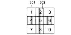
次に、図3及び図4は照射位置によって照射する超音波の強度を変えて治療を行う場合の照射マップを示す例である。
【0044】
照射位置によって照射する超音波の強度を変えて治療を行う場合がある。このような場合は、例えば、計画段階において、図3に示すように強度によって表示区分の色を薄い色301、濃い色302のように変えて表示すればその違いが分かりやすく、各照射位置に対して照射強度を誤ることを防ぐのに役立つ。
【0045】
しかしながら、このような色分けを照射前の表示として行うと、前記図2に示した照射済表示区分に対する塗りつぶしの方法では色の制限からも未照射/照射済の判断がつきにくい場合がある。このような場合は、図4に示すように照射済表示区分に対しては塗りつぶしでなく例えば×印401を付すようにすればよい。図4に示す×印401に限られることは無いが、このように色による未照射/照射済の区別をつけ辛い場合は塗りつぶし以外の方法を用いることが有効である。
【0046】
また、治療計画時に予定した強度と異なる超音波強度にて照射を実施した場合は、その照射位置に係る表示区分に対してその照射強度に対応する表示に事後修正できるようにしてもよい。
【0047】
本発明において、照射マップに示す照射順序は数字以外でもよく、例えば図5に示されるように矢印等によるものであってもよい。すなわち、照射順序を認識できるものであれば、その表示態様はどのようなものであってもよい。
【0048】
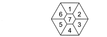
さらに、照射マップの形状については必ずしも行列からなるマトリクス形態である必要はない。例えば、図6に示すような六角形状等、いかなるものであってもよい。六角形に限らず多角形状や円形状などを用いれば治療対象に対して全体として円形状に照射する場合(後述の本発明の第2の実施の形態を参照)に有用である。
【0049】
さらにまた、操作者による超音波治療中に照射位置が計画と異なることが判明した場合や実際の照射位置との関係からのやむを得ない理由等により、照射マップの照射表示区分を増減する必要が生じた場合は、操作者は手動設定により表示区分の変更が可能である。この時、照射済区分にも変更を要する場合は適宜、操作者によって手動変更設定もできるようにするとよい。
【0050】
上記図2を用いて説明した照射マップ等の表示は、超音波診断機能に係る表示装置22、又はシステムコントローラ23の表示装置26において単独で表示されるようにしてもよいが、例えば、図7や図8に示すように他の情報と共に表示するようにしてもよい。
【0051】
図7は超音波治療装置1の超音波診断機能に係る表示装置22における表示画面の一例を示すものであり、本発明に係る照射マップ等を超音波画像701と共に表示する例を示す図である。同図に示すように、超音波画像701には治療対象(患部)702が写っており、この超音波画像701に重ねて超音波治療に係る焦点領域703が表示されている。このような超音波画像701等と共に照射マップ等が表示されることにより、操作者は治療対象702と焦点領域703の関係を把握しつつ超音波照射毎に実際の照射位置に対応する照射マップ上の表示区分を塗りつぶしていくことができる。
【0052】
また、図8はシステムコントローラ23の表示装置26における表示画面の一例を示すものであり、本発明に係る照射マップ等をシステム情報801と共に表示する例を示す図である。同図に示すように、システム情報801としては例えば各種照射条件があり、超音波照射に当たってこれらシステム情報801を参照しながら実施する方が好ましいと操作者が判断する場合に有用である。なお、表示装置26の表示画面には図7に示される超音波画像701は表示されないが、超音波照射にあたって超音波画像は表示装置22の画面を参照すればよい。
【0053】
いずれの場合も操作者が見やすい位置に表示装置22又は28を設置する。また、いずれの表示装置に表示させるかは操作者の見易さや参照情報によって異なる。
【0054】
以上説明したように、本発明の第1の実施の形態に係る超音波治療装置によれば、超音波の照射にあたって操作者は(次に)どの位置を照射すべきか、また、どの位置を既に照射したかを簡易な手段で知ることが可能となる。従って、未照射部分を残してしまうことや同一箇所を過剰照射してしまうことを避けることができるようになる。
【0055】
また、本発明に係る照射マップは実際の被検体の治療対象の絶対位置を表示するものではないが、超音波照射における照射位置について操作者の助けとなるものであり、従来のような大掛かりな装置や高価な装置を必要とすることなく上記効果を奏するものであるため、大病院等でなくても容易に導入できると共に実際の使用において照射ミスを防ぐのに十分な効果を奏するものである。
【0056】
なお、照射マップ等を検査記録として保存したり、電子カルテ等へ転載するようにしてもよい。
(第2の実施の形態)
次に、本発明の第2の実施の形態として三次元超音波診断機能を備えた超音波治療装置について説明する。
【0057】
図9は本発明の第2の実施の形態に係る、三次元超音波診断機能を備えた超音波治療装置の超音波プローブにより得られる超音波画像の垂直断層面及び水平断層面を示す図である。また、図10は図9に示される三次元超音波診断機能により得られる超音波画像の表示例を示す図である。
【0058】
超音波プローブ901は三次元情報を取得できる構造となっている。この超音波プローブ901はアプリケータに内蔵された超音波プローブでも良いし、例えば独立した超音波プローブ等でも良い。この超音波プローブ901によって治療対象(腫瘍)902を観察する。このとき、超音波プローブ901によって得られる断層面は、超音波プローブ901の軸に平行な垂直断層面903と、超音波プローブ901の軸に対して垂直方向な水平断層面904とからなる。水平断層面の位置は、前記水平断層面904を垂直移動方向905に従って移動させることにより、例えば水平断層面906に移動変更することが可能である。
【0059】
超音波治療装置の三次元超音波診断機能による前記垂直断層面903の画像はBモード表示画像1001として表示される。また、前記水平断層面904又は905はCモード表示画像1002として表示される。Bモード表示画像1001及びCモード表示画像1002のいずれにおいても治療対象1003が含まれており、また表示画面上では超音波照射の焦点領域1004が同時表示されている。なお、Bモード表示画像1001とCモード表示画像1002との間の表示関係を把握しやすくするため、Bモード表示画像1001上の一点鎖線1005はこの位置の断層面がCモード表示画像1002であること、Cモード表示画像1002上の一点鎖線1006はこの位置の断層面がBモード表示画像1001であることをそれぞれ示すようになっている。
【0060】
前記焦点領域1004は、治療用に照射される超音波が前記超音波プローブ901の軸方向(深さ方向)に伝搬するとしたときに1回の照射で治療できる領域である。Bモード表示画像1001を参照することで、深さ方向、すなわちBモード表示画像1001における上下方向について何枚の面で照射を行うべきか計画を立てることができる。さらに、Bモード表示画像1001及びCモード表示画像1002を参照することで治療対象1003に対して焦点領域1004の把握が前記深さ方向以外についても容易にできるので、前記深さ方向の治療面が1面であっても2面以上であっても、(それぞれの)面において何箇所の照射位置にどういう順番で超音波照射すべきかの計画を立てることも容易にできる。
【0061】
次に図11を参照して本発明の第2の実施の形態に係る治療計画について説明する。
【0062】
図11は超音波画像を用いて超音波治療に係る超音波照射の照射位置を指定する例を示す図である。
【0063】
同図に示す超音波治療装置の表示例は図10に示すものと同様に超音波画像としてBモード表示画像1101とCモード表示画像1102,1103が表示される例である。
【0064】
まず、Bモード表示画像1101を参照することにより腫瘍等の輪郭を指定する。輪郭の指定は、超音波治療装置の三次元超音波診断機能に係る操作盤、又はシステムコントローラに係る操作盤(入力部)に設置したトラックボールやスイッチ等の操作により行われる。輪郭の指定が行われると、この情報は治療対象1108としてBモード表示画像1101等の超音波画像上に表示される。
【0065】
Bモード表示画像1101上に前記治療対象1108が表示されると、次に、この治療対象1108に対して所定のマージン(余裕幅)を持った領域(以下、照射領域)1109を設定する。実際、例えば治療対象1108が肝臓の一部である場合、治療残しが無いことを優先して、治療対象1108たる腫瘍等のその治療部位に対してマージンをもって超音波を照射することが多い。この照射領域1109内を超音波照射すれば確実に治療対象1108に対して治療することができ、未照射部分を残してしまい治療不十分となることを防ぐことが可能となる。
【0066】
このマージンの幅は広く取りすぎると却って正常な箇所にも超音波照射してしまうことになり好ましくないので、図11に示すようにマージン選択パレット1110を設けて、治療対象に応じてそのマージンの幅を選択できるようにする。
【0067】
このようにして照射領域1109が設定されると、次に焦点領域1111の大きさが焦点領域選択パレット1112により選択設定される。この焦点領域選択パレット1112により1回の超音波照射により治療できる大きさが設定されると、その焦点領域1111で前記照射領域1109を埋めるように焦点領域1111が照射領域1109内に例えば自動的に配列表示される。
【0068】
焦点領域1111が配列表示された際に深さ方向に複数面(図11は2面の例)の照射が必要とされる場合はその照射面が例えば一点鎖線1104,1105で表示される。各面が決まるとこれに応じて、Bモード表示画像1101上の一点鎖線1104の位置における断層面の表示としてCモード表示画像1102、同様に、Bモード表示画像1101上の一点鎖線1105の位置における断層面の表示としてCモード表示画像1103がそれぞれ表示される。図11では2つの面において照射する例を示しているが、同図に示すように複数面のCモード表示画像を表示する際は深さの浅い方の面(図11の上側の面)から順に上から表示するようにしてもよい。一方、Cモード表示画像1102,1103上にはそれぞれ一点鎖線1106,1107によりBモード表示画像1101の位置が表される。
【0069】
また、Cモード表示画像1102,1103においてはBモード表示画像1101と同様に治療対象1108、照射領域1109、及び焦点領域1111が表示される。Cモード表示画像1102,1103上での治療対象1108の表示はBモード表示画像1101への指定に基づいて自動的に推定表示されるようにしてもよいし、Cモード表示画像1102,1103上で改めて腫瘍等の輪郭指定を行うことにより表示させるようにしてもよい。
【0070】
さらに、照射領域1109内において焦点領域1111を複数位置に表示(配列表示)するにあたり、これら複数の焦点領域1111の配列が形成する形状は予め焦点領域配列形状選択パレット1113により選択設定することができるようにしてもよい。図11においてはその形状が円形である場合が例示されている。前記焦点領域配列形状選択パレット1113により四角形が選択される場合は、図12に示すようなマトリクス状の形態で焦点領域1111が配列表示される。四角形の場合はマージンが大きくなる可能性もあるが、特に大きな問題となることがないような場合は、円形よりも四角形の方が超音波照射の実際の操作が行い易くなるため、この四角形状の配列で実施してもよい。
【0071】
なお、必要であれば、実際にアプリケータを持って位置合わせの確認を行い、焦点領域1111の配列位置、焦点領域の大きさ、等の修正を行う。
【0072】
照射領域と焦点領域1111及びその配列が定まると、次に第1の実施の形態と同様に照射マップを作成する。本実施の形態の場合も、被検体を擬似的に示すボディマークが表示され、そのボディマーク上に治療位置を示すマーカが表示される。
【0073】
マーカが決まると、そのマーカの向きに合わせて照射マップが表示される。本実施の形態の場合、既に焦点領域の数やその配列も決まっているので、その情報に従って作成されたマトリクスサイズの照射マップが表示される。
【0074】
照射マップには前記焦点領域に各々対応する表示区分が例えばマトリクス状に表示されるが、表示された各表示区分にはそれぞれ照射順序を付することができるのは第1の実施の形態において説明した通りである。各表示区分に対する照射順序は機械的に自動付与するようにしてもよいし、操作者が自身で照射しやすい順序に付与するようにしてもよい。また、開始表示区分のみ指定する等、一部を操作者による設定とし一部を機械的自動設定するようにしてもよい。
【0075】
以上のようにして照射位置(表示区分)と照射順序を示す照射マップが作成・表示されると、実際の超音波照射による治療が開始されることになる。照射に当たっては本発明の第1の実施の形態において説明したのと同様にして行われる。
【0076】
本実施の形態によれば、第1の実施の形態と異なり、三次元超音波診断機能により超音波プローブの軸に平行な垂直断層面と超音波プローブの軸に対して垂直方向な水平断層面の超音波画像を参照して照射領域及び超音波照射の焦点領域を設定することにより、第1の実施の形態のように操作者の経験や勘に頼るこ負担を軽減して照射マップを作成することができる。また、その照射マップの精度も操作者の経験や勘に頼る場合よりも高くなることが期待できる。
【0077】
さらに、第1の実施の形態の場合と同様に、照射マップの作成により、超音波の照射にあたって操作者はどの位置を既に照射したかを知ることが可能となる。従って、未照射部分を残してしまうことや同一箇所を過剰照射してしまうことを避けることができるようになる。
(変形例)
次に、前記第1及び第2の実施の形態のいずれにおいても適用可能な本発明の実施の形態の変形例について説明する。
【0078】
本変形例は照射領域の指定に関するものである。例えば、治療対象となる被検体内部位の近傍に血管が存在する場合、治療のための超音波照射はこの血管を避けて行われるべきである。つまり、太い血管などの重要器官を照射すると出血や閉塞の危険があるため、治療のための強い超音波照射を行わないようにすることが必要である。
【0079】
図13は前述した第2の実施の形態の場合と同じく三次元超音波診断機能を有する超音波治療装置におけるCモード表示画像で、治療対象近傍に血管が存在する場合の例を示す図である。血管1301及びその周辺は超音波照射をすべきでない領域(以下、照射禁止領域)とする。この血管1301の周りにマージンを取った照射禁止領域1302を設定すると、治療対象1303にマージンを持たせた照射領域1304における焦点領域1305の配列は前記照射禁止領域1302にかからないように自動又は手動により設定される。
【0080】
このようにして各焦点領域1305の位置が定まると、これらの位置に従って超音波照射を行う限り、前記照射禁止領域1302に対する照射を回避することができる。
【0081】
なお、前記焦点領域1305の配列について、図13は円形に配列される例を示したが、図12と同様、各焦点領域は四角形に配列されるようにしてもよい。
【0082】
図14は照射禁止領域を含む場合に焦点領域の配列を四角形にとった例を示す図である。アプリケータの位置を正確に移動できる場合は前述の図13のように円形でもよいが、操作者がアプリケータを手動で操作して移動させる場合には図14に示すような四角形の方が直線的になるのでアプリケータの操作制御が容易となる。図14から明らかなように、焦点領域1401の配列においては照射禁止領域1302を考慮して行われ、特に、照射禁止領域1302の近傍に配置される焦点領域1402等については前記照射禁止領域1302を避けるために通常の配置位置よりもずれた位置に配置される。
【0083】
このような焦点領域の配置に基づいて作成された照射マップは図15のようになる。図15は照射禁止領域を考慮した表示区分を有する照射マップを示しており、照射順序「1」乃至「3」が付された表示区分については他の表示区分とは異なる大きさからなり、結果として他の表示区分とはずれた配置になっている。通常、焦点領域を四角形に配列する場合、照射マップは全表示区分により四角形を形成するが、それぞれ照射順序「4」及び「7」が付された表示区分の間に照射禁止領域が来るため照射順序「1」が付された表示区分により凹形状となる。この凹形状により操作者は一目でこの位置に照射禁止領域が存在することを容易に想像することができ、操作者に対して注意を喚起する意味でも非常に有用である。
【0084】
なお、前述した通り、上記照射禁止領域を考慮した照射マップについては本発明の第1の実施の形態においても適用可能である。本発明の第1の実施の形態の場合、操作者が自ら照射マップを作成することになるが、予め照射マップを作成する段階で照射禁止領域を認識できているのであれば、それを照射マップに反映させることによって本番の超音波照射において操作者自身に注意喚起できるので、操作者が誤って照射禁止領域に存在する血管等に強い超音波を照射してしまうことを避けることができるようになる。これは特に、照射マップを作成する者と実際に超音波治療を行う者が異なる場合において大きな効果が期待できる。
【0085】
また、本発明においては超音波照射すべき治療対象の隣接部位の状況やさらには治療対象そのものの形状等により、適宜、照射マップの形状を変えて作成できるので、実際の超音波照射すべき位置について柔軟に対応することが可能となる。
【0086】
以上、2次元超音波診断機能を有する場合であっても3次元超音波診断機能を有する場合であっても、アプリケータを操作者が手で持って操作する場合について説明した。しかしながら、本発明においてはアプリケータを機械的に保持して照射領域内の照射位置を順次移動していく構成の場合であっても、照射マップの作成・表示、及び照射済み位置の表示を行うようにしてもよい。この場合もアプリケータの機械的な移動位置と照射マップが高い精度を持って対応している必要はない。
【0087】
また、超音波診断機能による画像ではなく、CT装置やMRI装置により得られた画像を用いて照射計画を立て照射マップを作成するようにしてもよい。
【0088】
さらに、照射マップに示す照射順序については、ある位置で照射した際に次の照射はできるだけ隣接しない位置で照射する場合もあるために、例えば、予め図16に示すような順序を付すようにしてもよい。
【0089】
さらにまた、照射マップには必ずしも照射順序を示す必要はない。作成された照射マップを参照しながら、照射済みの表示区分を塗りつぶすことにより操作者が未照射位置と照射済み位置を認識することができればよい。
【0090】
以上説明したように、本発明によれば超音波治療に際し、超音波照射すべき位置(とその照射順序)を計画した照射マップを簡易に作成・表示する。また、各照射位置での照射後に照射済位置に対応する照射マップ上の表示区分を照射済みの旨識別できるような表示を行う。従って、従来のような大掛かりな装置や高価な装置を用いる必要もなく、またそれらによる精密な位置合わせの技術を利用することを前提とせずとも、照射する位置と既に照射した位置の把握において操作者に助けを提供することができるため、同一箇所における過剰な照射や照射すべき位置での照射忘れを招く可能性を低減し、安全で確実な治療を可能せしめる超音波治療装置を提供することができる。
【0091】
【発明の効果】
本発明によれば、照射すべき位置と照射済み位置の認識を簡易な構成で可能せしめることにより、同一箇所への過剰照射や照射すべき箇所への照射忘れを防ぐことを可能とし、安全で確実な超音波治療を実現することができるようになる。
【図面の簡単な説明】
【図1】 本発明の第1の実施の形態に係る超音波治療装置の構成を示すブロック図。
【図2】 本発明の第1の実施の形態に係る照射マップの一例を示す図。
【図3】 照射位置によって照射する超音波の強度を変える場合の照射マップの一例を示す図。
【図4】 照射位置によって照射する超音波の強度を変える場合の照射済表示の一例を示す図。
【図5】 照射マップに照射順序を表示する一例を示す図。
【図6】 照射マップの形状の一例を示す図。
【図7】 本発明に係る照射マップ等を超音波画像と共に表示する一例を示す図。
【図8】 本発明に係る照射マップ等をシステム情報と共に表示する一例を示す図。
【図9】 本発明の第2の実施の形態に係る、三次元超音波診断機能を備えた超音波治療装置の超音波プローブにより得られる超音波画像の垂直断層面及び水平断層面を示す図。
【図10】 図9に示される三次元超音波診断機能により得られる超音波画像の表示例を示す図。
【図11】 超音波画像を用いて超音波治療に係る超音波照射の照射位置を指定する一例を示す図。
【図12】 マトリクス状の形態で焦点領域が配列表示される例を示す図。
【図13】 三次元超音波診断機能によるCモード表示画像において治療対象近傍に血管が存在する場合の例を示す図。
【図14】 照射禁止領域を含む場合に焦点領域の配列を四角形にとった例を示す図。
【図15】 照射禁止領域を考慮した表示区分を有する照射マップの一例を示す図。
【図16】 照射マップに照射順序を表示する別の例を示す図。
【符号の説明】
1・・・超音波治療装置
2・・・アプリケータ
3・・・超音波振動子
4,901・・・超音波プローブ
5・・・水袋
6・・・被検体
7,702,902,1003,1108,1303・・・治療対象
8・・・撮影領域
13・・・主制御部
22,26・・・表示装置
23・・・システムコントローラ
24・・・治療計画設定部
25・・・入力部
201・・・ボディマーク
202・・・マーカ
203,204・・・照射マップ
701・・・超音波画像
703,1004,1111,1305,1401,1402・・・焦点領域
903・・・垂直断層面
904,906・・・水平断層面
1001,1101・・・Bモード表示画像
1002,1102,1103・・・Cモード表示画像
1109,1304・・・照射領域
1301・・・血管
1302・・・照射禁止領域[0001]
BACKGROUND OF THE INVENTION
The present invention relates to an ultrasonic treatment apparatus that performs treatment in a subject using ultrasonic waves.
[0002]
[Prior art]
2. Description of the Related Art In recent years, there is known an ultrasonic therapy apparatus that irradiates a patient's body with ultrasonic waves and performs treatment using heat generated by absorption of ultrasonic waves in the body or mechanical action.
[0003]
In such a device, the ultrasonic wave generated outside the patient's body is focused inside the body, and in a limited area where the intensity of the ultrasonic wave near the focal point becomes high, a heating effect or mechanical force sufficient to obtain a therapeutic effect is obtained. The action is to occur. On the other hand, in other regions, safe and reliable treatment is performed by making it possible to ignore the influence of the action of ultrasonic waves on the living body. The treatable area near the focal point is generally referred to as the “focus area”.
[0004]
In general, since the size of the focal region is smaller than that of a treatment target such as a tumor, it is not possible to treat all of the treatment target with a single ultrasonic irradiation. Therefore, the entire treatment target is treated by irradiating the ultrasonic wave to a plurality of positions by changing the position where the ultrasonic wave is irradiated within the treatment target. During treatment, the order of irradiation at multiple positions within the treatment target is planned based on the ultrasound image before treatment, etc., and the procedure for setting and controlling the irradiation as planned is taken. (For example, see
[0005]
In addition, a three-dimensional image is created in advance by using an ultrasound image, CT image, MRI image, etc. for a treatment target such as a tumor, and when irradiation is performed, the location is calculated by a control circuit and the color is changed on the three-dimensional image. For example, a device that can clearly indicate an irradiated portion and an unirradiated portion (see, for example, Patent Document 3).
[0006]
On the other hand, for the treatment of liver cancer, for example, an operator manually operates a unit called an applicator in which an element for generating ultrasonic waves for treatment and an ultrasonic probe for observing a treatment target are integrated, and performs positioning. It is also practiced to irradiate an area with a margin added to the gun in multiple times. In this case, the plan and display method as shown in the above example are not used. In addition, there is a case where it becomes difficult to check an image (particularly, an irradiation adjacent portion) due to ultrasonic irradiation, and it becomes difficult to check an image (particularly an irradiation adjacent portion), and it is necessary to irradiate another position in a different order from the plan.
[0007]
[Patent Document 1]
JP-A-8-24267 (
[0008]
[Patent Document 2]
Japanese Patent Laid-Open No. 11-164837 (
[0009]
[Patent Document 3]
JP-A-11-313833 (5th page, FIG. 6)
[0010]
[Problems to be solved by the invention]
In the case of the examples shown in the
[0011]
Actually, in order to realize these preconditions, etc., the system becomes more complicated, the occupied space becomes large, and the cost becomes high. Furthermore, there are cases where it cannot be easily realized technically. In addition, margins and areas that should not be irradiated cannot be specified in the treatment plan, and it is not possible to respond flexibly to actual operations, such as being unable to respond to changes in the irradiation order during the execution display. There was also a problem.
[0012]
On the other hand, in the treatment of liver cancer shown above, since the irradiation position is not planned or displayed, the operator may forget the irradiated position when the irradiation order is changed. There was a risk of causing problems such as over-irradiation at the same position and leaving an unirradiated part.
[0013]
SUMMARY OF THE INVENTION An object of the present invention is to provide an ultrasonic treatment apparatus that enables easy planning of irradiation positions and display of irradiated positions and enables reliable treatment.
[0014]
[Means for Solving the Problems]
In order to achieve the above object, an ultrasonic therapy apparatus according to the present invention includes an ultrasonic irradiation means for irradiating a predetermined portion of a subject with ultrasonic waves, and an irradiation map for displaying the predetermined portion separately. A creation means for creating, an input means for inputting an irradiation order for the irradiation map, an irradiation map created by the creation means, and an irradiation order based on the input means for displaying the irradiation map Display means for displaying on Recognizing the end of irradiation each time irradiation is performed sequentially according to the irradiation order based on the input means, in order according to the irradiation order based on the input means, And a display control means for displaying the irradiated identification for each display section of the irradiation map displayed on the display means.
[0015]
According to the present invention, with the simple configuration, the operator can easily grasp the irradiation position and the unirradiated position / irradiated position by the irradiation map, and leave the excessive irradiation and the unirradiated portion at the same position. It is possible to prevent the occurrence of the problem. Therefore, safe and reliable ultrasonic treatment can be realized.
[0016]
DETAILED DESCRIPTION OF THE INVENTION
Embodiments of the present invention will be described below with reference to the drawings.
(First embodiment)
FIG. 1 is a block diagram showing the configuration of the ultrasonic therapy apparatus according to the first embodiment of the present invention. As shown in the figure, the
[0017]
The ultrasonic wave irradiated from the
[0018]
In addition, it is possible to confirm the state in the subject by capturing an ultrasound image in the
[0019]
By the way, each of the
[0020]
The
[0021]
On the other hand, the
[0022]
Note that each unit forming the ultrasonic diagnostic apparatus, the
[0023]
Next, ultrasonic irradiation for treatment will be described.
[0024]
In the
[0025]
For example, prior to treatment, the position, size, shape, etc. of the
[0026]
Furthermore, regardless of whether or not information on the
[0027]
Usually, since the size of the focal region is often smaller than the size of the treatment target, a plan is set so that a plurality of focal regions are set for the treatment target and the
[0028]
Hereinafter, a case where treatment is performed while holding the
[0029]
FIG. 2 is a diagram showing an example of an irradiation map according to the first embodiment of the present invention. The irradiation map is a plurality of positions necessary for irradiation when one irradiation is not sufficient for the
[0030]
As shown in the figure, first, a
[0031]
When the
[0032]
In addition, when it is necessary to irradiate two or more surfaces in the depth direction, the irradiation is performed from the deeper surface (the surface having the far focal distance from the ultrasonic transducer 3) (
[0033]
By the way, as described above, the operator can grasp the position, size, shape, and the like of the
[0034]
In the irradiation maps 203 and 204, an irradiation order can be assigned for each display section displayed in a matrix. As described above, when there are two irradiation surfaces, the irradiation order is given in order from the
[0035]
When the irradiation maps 203 and 204 indicating the irradiation position and the irradiation order are created and displayed as described above, treatment by actual ultrasonic irradiation is started. In accordance with the irradiation maps 203 and 204 created in advance, the operator starts ultrasonic irradiation from the focal region corresponding to the position with the order “1”.
[0036]
When the irradiation in the focal region of the irradiation order “1” is completed, the display section “1” is automatically filled in response to the recognition of the end of the irradiation action (if it can be distinguished from other unirradiated sections). Any embodiment may be used. Thus, when it irradiates sequentially according to an irradiation order, a display division is filled in the order set according to recognition of the end of irradiation each time.
[0037]
In this way, since the irradiated position is displayed on the irradiation map without omission and without overlapping, the operator can perform reliable and safe ultrasonic treatment.
[0038]
By the way, in performing ultrasonic irradiation, once irradiation is performed at a certain position, the ultrasonic irradiation may cause a high echo state on the ultrasonic image. In such a case, it is difficult to confirm the ultrasonic image (particularly the irradiation adjacent region), and when the adjacent region is set to the next irradiation order, the adjacent region may not be irradiated as planned. Therefore, there are cases where it is necessary to irradiate different irradiation positions in an order different from the plan.
[0039]
In such a case, for example, the focus area corresponding to the display section represented by the irradiation order “1” is followed by the irradiation order “3”, not the focus area corresponding to the display section represented by the irradiation order “2”. The focus area corresponding to the displayed display section is irradiated. Therefore, if the display section “3” is not filled instead of the display section “2” on the
[0040]
In addition, when performing an operator's manual filling, as the method, for example, a method of recognizing an operator's voice and performing an operation so as to fill a corresponding display section can be considered. For example, since the display classification can be indicated only by numbers, it is sufficient that only simple words can be recognized, and there is little possibility of malfunctioning in view of recent speech recognition technology. Accordingly, the painting using the voice recognition technology is a useful means in addition to the fact that the operator does not have to bother directly with the painting operation. In addition, since a correction operation may be necessary, it is preferable that simple terms related to error correction can be recognized.
[0041]
In addition, manually irradiating the illuminated display section may be configured so that the operator can directly indicate the position by making the
[0042]
Furthermore, if the operator of the ultrasonic treatment apparatus has an assistant, the assistant may input the irradiation display section manually by inputting from the
[0043]
Next, FIG. 3 and FIG. 4 are examples showing irradiation maps in the case where treatment is performed by changing the intensity of ultrasonic waves to be irradiated depending on the irradiation position.
[0044]
There are cases where treatment is performed by changing the intensity of ultrasonic waves to be irradiated depending on the irradiation position. In such a case, for example, in the planning stage, if the display section color is changed to
[0045]
However, if such color coding is performed as a display before irradiation, it may be difficult to determine whether the irradiation has been performed or not, due to color limitations, in the method of filling the irradiated display section shown in FIG. In such a case, as shown in FIG. 4, for example, an
[0046]
Further, when irradiation is performed with an ultrasonic intensity different from the intensity planned at the time of treatment planning, the display classification corresponding to the irradiation position may be corrected afterwards to a display corresponding to the irradiation intensity.
[0047]
In the present invention, the irradiation order shown in the irradiation map may be other than numerals, for example, as shown in FIG. That is, as long as the irradiation order can be recognized, any display mode may be used.
[0048]
Furthermore, the shape of the irradiation map is not necessarily in the form of a matrix composed of matrices. For example, any hexagonal shape as shown in FIG. 6 may be used. Use of not only a hexagonal shape but also a polygonal shape or a circular shape is useful when the treatment target is irradiated in a circular shape as a whole (see a second embodiment of the present invention described later).
[0049]
Furthermore, it is necessary to increase or decrease the irradiation display category of the irradiation map when it is found that the irradiation position is different from the plan during the ultrasonic treatment by the operator or because it is unavoidable from the relationship with the actual irradiation position. In such a case, the operator can change the display category by manual setting. At this time, if it is necessary to change the irradiated category, it is preferable that the operator can also perform manual change setting as appropriate.
[0050]
The display of the irradiation map or the like described with reference to FIG. 2 may be displayed alone on the
[0051]
FIG. 7 shows an example of a display screen on the
[0052]
FIG. 8 shows an example of a display screen on the
[0053]
In either case, the
[0054]
As described above, according to the ultrasonic therapy apparatus according to the first embodiment of the present invention, the operator should (next) irradiate the ultrasonic wave and which position has already been applied. It becomes possible to know whether the irradiation has been performed by a simple means. Therefore, it is possible to avoid leaving an unirradiated part and excessively irradiating the same part.
[0055]
In addition, the irradiation map according to the present invention does not display the absolute position of the treatment target of the actual subject, but is intended to assist the operator with respect to the irradiation position in the ultrasonic irradiation, and is not as large as in the past. Since the above effect is achieved without the need for a device or an expensive device, it can be easily introduced without being in a large hospital or the like, and has a sufficient effect to prevent an irradiation error in actual use. .
[0056]
Note that an irradiation map or the like may be stored as an inspection record or reprinted on an electronic medical record or the like.
(Second Embodiment)
Next, an ultrasonic therapy apparatus having a three-dimensional ultrasonic diagnostic function will be described as a second embodiment of the present invention.
[0057]
FIG. 9 is a diagram showing a vertical tomographic plane and a horizontal tomographic plane of an ultrasonic image obtained by an ultrasonic probe of an ultrasonic therapy apparatus having a three-dimensional ultrasonic diagnostic function according to the second embodiment of the present invention. is there. FIG. 10 is a view showing a display example of an ultrasonic image obtained by the three-dimensional ultrasonic diagnostic function shown in FIG.
[0058]
The
[0059]
An image of the
[0060]
The
[0061]
Next, a treatment plan according to the second embodiment of the present invention will be described with reference to FIG.
[0062]
FIG. 11 is a diagram illustrating an example of designating an irradiation position of ultrasonic irradiation related to ultrasonic therapy using an ultrasonic image.
[0063]
The display example of the ultrasonic therapy apparatus shown in the figure is an example in which a B-
[0064]
First, an outline of a tumor or the like is designated by referring to the B-
[0065]
When the
[0066]
If the width of this margin is too wide, it is not preferable because the normal portion is also irradiated with ultrasonic waves, so a
[0067]
When the
[0068]
When irradiation of a plurality of surfaces (example of two surfaces in FIG. 11) is required in the depth direction when the
[0069]
In the C
[0070]
Further, when displaying the
[0071]
If necessary, the registration is actually confirmed by holding the applicator, and the arrangement position of the
[0072]
When the irradiation area, the
[0073]
When a marker is determined, an irradiation map is displayed according to the direction of the marker. In the case of the present embodiment, since the number of focal regions and their arrangement are already determined, an irradiation map having a matrix size created according to the information is displayed.
[0074]
In the irradiation map, display sections corresponding to the focal areas are displayed in a matrix, for example, and the display order can be assigned to the displayed display sections as described in the first embodiment. That's right. The irradiation order for each display section may be automatically given mechanically, or may be given in an order that the operator can easily irradiate. Alternatively, a part may be set by the operator, for example, only the start display section may be designated, and a part may be mechanically automatically set.
[0075]
When the irradiation map indicating the irradiation position (display category) and the irradiation order is created and displayed as described above, treatment by actual ultrasonic irradiation is started. Irradiation is performed in the same manner as described in the first embodiment of the present invention.
[0076]
According to the present embodiment, unlike the first embodiment, a vertical tomographic plane parallel to the axis of the ultrasonic probe and a horizontal tomographic plane perpendicular to the axis of the ultrasonic probe by the three-dimensional ultrasonic diagnostic function. By setting the irradiation area and the focal area of the ultrasonic irradiation with reference to the ultrasonic image of, an irradiation map is created by reducing the burden of relying on the experience and intuition of the operator as in the first embodiment. can do. In addition, the accuracy of the irradiation map can be expected to be higher than when relying on the experience and intuition of the operator.
[0077]
Furthermore, as in the case of the first embodiment, by creating an irradiation map, the operator can know which position has already been irradiated in the irradiation of ultrasonic waves. Therefore, it is possible to avoid leaving an unirradiated part and excessively irradiating the same part.
(Modification)
Next, a modification of the embodiment of the present invention that can be applied to both the first and second embodiments will be described.
[0078]
This modification relates to the designation of the irradiation area. For example, when a blood vessel exists in the vicinity of a site in a subject to be treated, ultrasonic irradiation for treatment should be performed while avoiding the blood vessel. In other words, if an important organ such as a thick blood vessel is irradiated, there is a risk of bleeding or occlusion. Therefore, it is necessary not to perform intense ultrasonic irradiation for treatment.
[0079]
FIG. 13 is a C-mode display image in an ultrasonic therapy apparatus having a three-dimensional ultrasonic diagnostic function as in the case of the second embodiment described above, and shows an example in the case where a blood vessel exists in the vicinity of the treatment target. . The
[0080]
When the position of each
[0081]
Note that FIG. 13 shows an example in which the
[0082]
FIG. 14 is a diagram showing an example in which the focal region is arranged in a square when the irradiation prohibited region is included. When the position of the applicator can be accurately moved, it may be circular as shown in FIG. 13 described above. However, when the operator manually moves the applicator and moves it, a quadrangle as shown in FIG. 14 is more linear. Therefore, the operation control of the applicator becomes easy. As is clear from FIG. 14, the arrangement of the
[0083]
An irradiation map created based on the arrangement of the focal areas is as shown in FIG. FIG. 15 shows an irradiation map having display sections in consideration of irradiation prohibited areas. The display sections with irradiation orders “1” to “3” have different sizes from the other display sections, and the result As shown in FIG. Normally, when the focus areas are arranged in a quadrangle, the irradiation map forms a quadrangle with all display sections, but the irradiation prohibition area comes between the display sections with the irradiation orders “4” and “7”, respectively. The display section with the order “1” has a concave shape. With this concave shape, the operator can easily imagine that there is an irradiation prohibited area at this position at a glance, and this is very useful in calling attention to the operator.
[0084]
As described above, the irradiation map in consideration of the irradiation prohibited area can also be applied in the first embodiment of the present invention. In the case of the first embodiment of the present invention, the operator creates the irradiation map by himself / herself. If the irradiation prohibited area can be recognized in advance at the stage of creating the irradiation map, the irradiation map is used. By reflecting it on the operator, it is possible to alert the operator himself in actual ultrasonic irradiation, so that the operator can avoid accidentally irradiating strong ultrasonic waves to blood vessels etc. existing in the irradiation prohibited area Become. In particular, a great effect can be expected when the person who creates the irradiation map is different from the person who actually performs the ultrasonic treatment.
[0085]
Further, in the present invention, since the shape of the irradiation map can be appropriately changed depending on the condition of the adjacent portion of the treatment target to be irradiated with ultrasonic waves, or the shape of the treatment target itself, the actual position to be irradiated with ultrasonic waves It is possible to respond flexibly.
[0086]
As described above, the case where the operator holds the applicator with the hand regardless of whether it has the two-dimensional ultrasonic diagnostic function or the three-dimensional ultrasonic diagnostic function has been described. However, in the present invention, even if the applicator is mechanically held and the irradiation position in the irradiation region is sequentially moved, the irradiation map is created and displayed, and the irradiation position is displayed. You may do it. In this case as well, the mechanical movement position of the applicator and the irradiation map need not correspond with high accuracy.
[0087]
In addition, an irradiation map may be created by creating an irradiation plan using an image obtained by a CT apparatus or an MRI apparatus instead of an image obtained by the ultrasonic diagnostic function.
[0088]
Furthermore, as for the irradiation order shown in the irradiation map, when the irradiation is performed at a certain position, the next irradiation may be performed at a position that is not adjacent as much as possible. For example, the order shown in FIG. Also good.
[0089]
Furthermore, the irradiation map does not necessarily indicate the irradiation order. It is only necessary that the operator can recognize the unirradiated position and the irradiated position by painting the irradiated display section while referring to the created irradiation map.
[0090]
As described above, according to the present invention, in the ultrasonic treatment, an irradiation map in which the position (and the irradiation order) where the ultrasonic irradiation is to be planned is easily created and displayed. Further, after the irradiation at each irradiation position, display is performed so that the display category on the irradiation map corresponding to the irradiated position can be identified as having been irradiated. Therefore, it is not necessary to use a conventional large-scale device or an expensive device, and it is not necessary to use precise alignment technology by them, and operation is performed in grasping the irradiation position and the already irradiated position. To provide an ultrasonic therapy apparatus that can provide safe and reliable treatment by reducing the possibility of over-irradiation at the same location and forgetting irradiation at the position to be irradiated because it can provide help to the elderly Can do.
[0091]
【The invention's effect】
According to the present invention, by enabling recognition of the position to be irradiated and the irradiated position with a simple configuration, it is possible to prevent over-irradiation to the same part and forgetting to irradiate the part to be irradiated. Reliable ultrasonic therapy can be realized.
[Brief description of the drawings]
FIG. 1 is a block diagram showing a configuration of an ultrasonic therapy apparatus according to a first embodiment of the present invention.
FIG. 2 is a diagram showing an example of an irradiation map according to the first embodiment of the present invention.
FIG. 3 is a diagram showing an example of an irradiation map when changing the intensity of ultrasonic waves to be irradiated depending on the irradiation position.
FIG. 4 is a diagram showing an example of an irradiation display when changing the intensity of ultrasonic waves to be irradiated depending on the irradiation position.
FIG. 5 is a diagram showing an example of displaying an irradiation order on an irradiation map.
FIG. 6 is a diagram showing an example of the shape of an irradiation map.
FIG. 7 is a view showing an example of displaying an irradiation map and the like according to the present invention together with an ultrasonic image.
FIG. 8 is a view showing an example of displaying an irradiation map and the like according to the present invention together with system information.
FIG. 9 is a view showing a vertical tomographic plane and a horizontal tomographic plane of an ultrasonic image obtained by an ultrasonic probe of an ultrasonic therapy apparatus having a three-dimensional ultrasonic diagnostic function according to a second embodiment of the present invention. .
10 is a diagram showing a display example of an ultrasonic image obtained by the three-dimensional ultrasonic diagnostic function shown in FIG.
FIG. 11 is a diagram showing an example of designating an irradiation position of ultrasonic irradiation related to ultrasonic therapy using an ultrasonic image.
FIG. 12 is a diagram showing an example in which focal regions are arranged and displayed in a matrix form.
FIG. 13 is a diagram showing an example when a blood vessel exists in the vicinity of a treatment target in a C-mode display image by a three-dimensional ultrasonic diagnostic function.
FIG. 14 is a diagram illustrating an example in which the focal region is arranged in a quadrangle when an irradiation prohibited region is included.
FIG. 15 is a diagram showing an example of an irradiation map having display sections in consideration of irradiation prohibited areas.
FIG. 16 is a diagram showing another example of displaying the irradiation order on the irradiation map.
[Explanation of symbols]
1 ... Ultrasonic therapy device
2 ... Applicator
3. Ultrasonic transducer
4,901 ... Ultrasonic probe
5 ... water bag
6 ... Subject
7,702,902,1003,1108,1303 ... treatment target
8 ... Shooting area
13 ... Main control unit
22, 26... Display device
23 ... System controller
24 ... Treatment plan setting part
25 ... Input section
201 ... Body Mark
202 ... Marker
203, 204 ... Irradiation map
701 ... Ultrasonic image
703, 1004, 1111, 1305, 1401, 1402 ... focal region
903 ... Vertical fault plane
904,906 ... Horizontal fault plane
1001, 1101... B mode display image
1002, 1102, 1103... C mode display image
1109, 1304 ... Irradiation area
1301 ... Blood vessels
1302 ... Irradiation prohibited area
Claims (13)
前記所定部位を区分表示する照射マップを作成する作成手段と、
前記照射マップに対して照射順序を示すための入力をする入力手段と、
前記作成手段により作成された照射マップを表示するとともに、前記入力手段に基づく照射順序を前記照射マップに対して表示する表示手段と、
前記入力手段に基づく照射順序に応じて順次照射される都度、照射終了を認識して、前記入力手段に基づく照射順序に従って順番に、前記表示手段に表示される照射マップの表示区分毎に照射済の識別表示をする表示制御手段とを具備することを特徴とする超音波治療装置。Ultrasonic irradiation means for irradiating a predetermined portion of the subject with ultrasonic waves;
Creating means for creating an irradiation map for displaying the predetermined part separately;
Input means for inputting an irradiation order for the irradiation map;
Displaying the irradiation map created by the creating means, and displaying the irradiation order based on the input means for the irradiation map;
Each time irradiation is sequentially performed according to the irradiation order based on the input means, the end of the irradiation is recognized, and irradiation is performed for each display section of the irradiation map displayed on the display means in order according to the irradiation order based on the input means. An ultrasonic therapy apparatus comprising: a display control means for performing identification display.
この超音波発生装置により得られる超音波画像の所定部位に対して複数の位置を設定するための設定手段と
をさらに具備し、前記作成手段は前記設定手段により設定された複数の位置に対応する区分表示の照射マップを作成することを特徴とする請求項1に記載の超音波治療装置。An ultrasonic generator for generating ultrasonic waves for observing the inside of the subject;
Setting means for setting a plurality of positions with respect to a predetermined part of an ultrasonic image obtained by the ultrasonic generator, wherein the creating means corresponds to the plurality of positions set by the setting means. The ultrasonic therapy apparatus according to claim 1, wherein an irradiation map of section display is created.
Priority Applications (1)
| Application Number | Priority Date | Filing Date | Title |
|---|---|---|---|
| JP2002272850A JP4127640B2 (en) | 2002-09-19 | 2002-09-19 | Ultrasonic therapy device |
Applications Claiming Priority (1)
| Application Number | Priority Date | Filing Date | Title |
|---|---|---|---|
| JP2002272850A JP4127640B2 (en) | 2002-09-19 | 2002-09-19 | Ultrasonic therapy device |
Publications (2)
| Publication Number | Publication Date |
|---|---|
| JP2004105502A JP2004105502A (en) | 2004-04-08 |
| JP4127640B2 true JP4127640B2 (en) | 2008-07-30 |
Family
ID=32269765
Family Applications (1)
| Application Number | Title | Priority Date | Filing Date |
|---|---|---|---|
| JP2002272850A Expired - Fee Related JP4127640B2 (en) | 2002-09-19 | 2002-09-19 | Ultrasonic therapy device |
Country Status (1)
| Country | Link |
|---|---|
| JP (1) | JP4127640B2 (en) |
Families Citing this family (16)
| Publication number | Priority date | Publication date | Assignee | Title |
|---|---|---|---|---|
| JP2006087599A (en) * | 2004-09-22 | 2006-04-06 | Toshiba Corp | Ultrasonic diagnostic equipment |
| JP4612379B2 (en) * | 2004-09-22 | 2011-01-12 | 株式会社東芝 | Medical image diagnosis support system, medical image diagnosis support device, medical image diagnosis support method, computer-readable storage medium, and computer program |
| WO2007004670A1 (en) * | 2005-07-05 | 2007-01-11 | Kaneka Corporation | Methacrylic resin composition |
| JP4790384B2 (en) * | 2005-11-15 | 2011-10-12 | 学校法人慈恵大学 | Ultrasound diagnostic treatment device |
| JP5380079B2 (en) * | 2009-01-06 | 2014-01-08 | 株式会社東芝 | Ultrasound treatment support apparatus and ultrasound treatment support program |
| JP5397938B2 (en) * | 2009-02-16 | 2014-01-22 | ジーイー・メディカル・システムズ・グローバル・テクノロジー・カンパニー・エルエルシー | MEDICAL IMAGE CREATION DEVICE AND PROGRAM |
| JP5689591B2 (en) * | 2009-06-01 | 2015-03-25 | 株式会社東芝 | Ultrasonic diagnostic apparatus and ultrasonic image processing program |
| US9474565B2 (en) | 2009-09-22 | 2016-10-25 | Mederi Therapeutics, Inc. | Systems and methods for treating tissue with radiofrequency energy |
| US9775664B2 (en) | 2009-09-22 | 2017-10-03 | Mederi Therapeutics, Inc. | Systems and methods for treating tissue with radiofrequency energy |
| US9750563B2 (en) | 2009-09-22 | 2017-09-05 | Mederi Therapeutics, Inc. | Systems and methods for treating tissue with radiofrequency energy |
| EP2480152B1 (en) | 2009-09-22 | 2018-08-29 | Mederi Therapeutics Inc. | Systems for controlling use and operation of a family of different treatment devices |
| JP5707148B2 (en) * | 2010-01-27 | 2015-04-22 | 株式会社東芝 | Medical image diagnostic apparatus and medical image processing apparatus |
| JP2012045198A (en) * | 2010-08-27 | 2012-03-08 | Hitachi Medical Corp | Treatment support device, and treatment support system |
| JP5779027B2 (en) * | 2011-07-25 | 2015-09-16 | 株式会社日立メディコ | Ultrasonic therapy device |
| WO2013117991A1 (en) * | 2012-02-06 | 2013-08-15 | Insightec, Ltd. | Reference-based motion tracking during non-invasive therapy |
| BR112014025063A8 (en) | 2012-04-12 | 2018-02-06 | Koninklijke Philips Nv | MEDICAL EQUIPMENT AND COMPUTER PROGRAM PRODUCT |
-
2002
- 2002-09-19 JP JP2002272850A patent/JP4127640B2/en not_active Expired - Fee Related
Also Published As
| Publication number | Publication date |
|---|---|
| JP2004105502A (en) | 2004-04-08 |
Similar Documents
| Publication | Publication Date | Title |
|---|---|---|
| JP4127640B2 (en) | Ultrasonic therapy device | |
| EP1611457B1 (en) | Guidance of invasive medical devices by wide view three dimensional ultrasonic imaging | |
| US4787394A (en) | Ultrasound therapy apparatus | |
| US20100286518A1 (en) | Ultrasound system and method to deliver therapy based on user defined treatment spaces | |
| US20100286520A1 (en) | Ultrasound system and method to determine mechanical properties of a target region | |
| US20050038339A1 (en) | Ultrasonic treatment of breast cancer | |
| US20060270934A1 (en) | Guidance of invasive medical devices with combined three dimensional ultrasonic imaging system | |
| BRPI1001591A2 (en) | ultrasound imaging and therapy system and therapy delivery method | |
| CN106102594A (en) | For performing system and the operational approach thereof that intraluminal tissue destroys | |
| US8740797B2 (en) | Ultrasonic therapeutic apparatus | |
| JP2007152094A (en) | Ablation array with independently operated ablation element | |
| JPWO2006068103A1 (en) | Ultrasonic diagnostic system and method | |
| KR20070060676A (en) | High intensity focus ultrasound system | |
| US20170150942A1 (en) | Ultrasonic diagnostic apparatus | |
| Dera et al. | Experimental evaluation of targeting accuracy of ultrasound imaging-guided robotic HIFU ablative system for the treatment of solid tumors in pre-clinical studies | |
| JPH08173449A (en) | Method to operate microscope for operation | |
| WO2015186651A1 (en) | Ultrasound therapeutic device and ultrasound therapeutic system | |
| CN107073287B (en) | The ultrasonography of radiation treatment procedure guides | |
| JP5611754B2 (en) | Surgery support system | |
| JP6297411B2 (en) | Ultrasonic therapy apparatus and ultrasonic therapy system | |
| JP4790384B2 (en) | Ultrasound diagnostic treatment device | |
| JP2937344B2 (en) | Ultrasound therapy equipment | |
| WO1995001125A1 (en) | Apparatus for speckle tracking in tissue | |
| JPH0824268A (en) | Impulse wave treating apparatus and thermal treating apparatus | |
| JP6246843B2 (en) | Medical system and display method |
Legal Events
| Date | Code | Title | Description |
|---|---|---|---|
| RD02 | Notification of acceptance of power of attorney |
Free format text: JAPANESE INTERMEDIATE CODE: A7422 Effective date: 20050427 |
|
| RD04 | Notification of resignation of power of attorney |
Free format text: JAPANESE INTERMEDIATE CODE: A7424 Effective date: 20050620 |
|
| A621 | Written request for application examination |
Free format text: JAPANESE INTERMEDIATE CODE: A621 Effective date: 20050819 |
|
| A977 | Report on retrieval |
Free format text: JAPANESE INTERMEDIATE CODE: A971007 Effective date: 20070907 |
|
| A131 | Notification of reasons for refusal |
Free format text: JAPANESE INTERMEDIATE CODE: A131 Effective date: 20070914 |
|
| A521 | Request for written amendment filed |
Free format text: JAPANESE INTERMEDIATE CODE: A523 Effective date: 20071109 |
|
| RD03 | Notification of appointment of power of attorney |
Free format text: JAPANESE INTERMEDIATE CODE: A7423 Effective date: 20071109 |
|
| A521 | Request for written amendment filed |
Free format text: JAPANESE INTERMEDIATE CODE: A821 Effective date: 20071109 |
|
| A02 | Decision of refusal |
Free format text: JAPANESE INTERMEDIATE CODE: A02 Effective date: 20080108 |
|
| A521 | Request for written amendment filed |
Free format text: JAPANESE INTERMEDIATE CODE: A523 Effective date: 20080310 |
|
| A911 | Transfer to examiner for re-examination before appeal (zenchi) |
Free format text: JAPANESE INTERMEDIATE CODE: A911 Effective date: 20080317 |
|
| TRDD | Decision of grant or rejection written | ||
| A01 | Written decision to grant a patent or to grant a registration (utility model) |
Free format text: JAPANESE INTERMEDIATE CODE: A01 Effective date: 20080507 |
|
| A01 | Written decision to grant a patent or to grant a registration (utility model) |
Free format text: JAPANESE INTERMEDIATE CODE: A01 |
|
| A61 | First payment of annual fees (during grant procedure) |
Free format text: JAPANESE INTERMEDIATE CODE: A61 Effective date: 20080509 |
|
| FPAY | Renewal fee payment (event date is renewal date of database) |
Free format text: PAYMENT UNTIL: 20110523 Year of fee payment: 3 |
|
| FPAY | Renewal fee payment (event date is renewal date of database) |
Free format text: PAYMENT UNTIL: 20110523 Year of fee payment: 3 |
|
| FPAY | Renewal fee payment (event date is renewal date of database) |
Free format text: PAYMENT UNTIL: 20110523 Year of fee payment: 3 |
|
| FPAY | Renewal fee payment (event date is renewal date of database) |
Free format text: PAYMENT UNTIL: 20120523 Year of fee payment: 4 |
|
| FPAY | Renewal fee payment (event date is renewal date of database) |
Free format text: PAYMENT UNTIL: 20120523 Year of fee payment: 4 |
|
| FPAY | Renewal fee payment (event date is renewal date of database) |
Free format text: PAYMENT UNTIL: 20130523 Year of fee payment: 5 |
|
| FPAY | Renewal fee payment (event date is renewal date of database) |
Free format text: PAYMENT UNTIL: 20130523 Year of fee payment: 5 |
|
| FPAY | Renewal fee payment (event date is renewal date of database) |
Free format text: PAYMENT UNTIL: 20140523 Year of fee payment: 6 |
|
| LAPS | Cancellation because of no payment of annual fees |