JP4127408B2 - Sheet metal rocker arm manufacturing method - Google Patents

Sheet metal rocker arm manufacturing method Download PDF

Info

Publication number
JP4127408B2
JP4127408B2 JP2006028710A JP2006028710A JP4127408B2 JP 4127408 B2 JP4127408 B2 JP 4127408B2 JP 2006028710 A JP2006028710 A JP 2006028710A JP 2006028710 A JP2006028710 A JP 2006028710A JP 4127408 B2 JP4127408 B2 JP 4127408B2
Authority
JP
Japan
Prior art keywords
base plate
rocker arm
sheet metal
thickness
engaging portion
Prior art date
Legal status (The legal status is an assumption and is not a legal conclusion. Google has not performed a legal analysis and makes no representation as to the accuracy of the status listed.)
Expired - Fee Related
Application number
JP2006028710A
Other languages
Japanese (ja)
Other versions
JP2006136947A5 (en
JP2006136947A (en
Inventor
聡 角川
則之 竹尾
芳博 斉藤
志信 島田
Current Assignee (The listed assignees may be inaccurate. Google has not performed a legal analysis and makes no representation or warranty as to the accuracy of the list.)
TOHO INDUSTRIAL CO., LTD.
NSK Ltd
Original Assignee
TOHO INDUSTRIAL CO., LTD.
NSK Ltd
Priority date (The priority date is an assumption and is not a legal conclusion. Google has not performed a legal analysis and makes no representation as to the accuracy of the date listed.)
Filing date
Publication date
Application filed by TOHO INDUSTRIAL CO., LTD., NSK Ltd filed Critical TOHO INDUSTRIAL CO., LTD.
Priority to JP2006028710A priority Critical patent/JP4127408B2/en
Publication of JP2006136947A publication Critical patent/JP2006136947A/en
Publication of JP2006136947A5 publication Critical patent/JP2006136947A5/ja
Application granted granted Critical
Publication of JP4127408B2 publication Critical patent/JP4127408B2/en
Anticipated expiration legal-status Critical
Expired - Fee Related legal-status Critical Current

Links

Images

Landscapes

  • Valve-Gear Or Valve Arrangements (AREA)
  • Forging (AREA)
  • Shaping Metal By Deep-Drawing, Or The Like (AREA)

Description

この発明は、エンジンの動弁機構に組み込み、カムシャフトの回転を弁体(吸気弁及び排気弁)の往復運動に変換する為のロッカーアームのうち、金属板にプレス加工を施す事により造る、板金製ロッカーアームの製造方法の改良に関する。   This invention is built into a valve mechanism of an engine, and is made by pressing a metal plate among rocker arms for converting the rotation of a camshaft into a reciprocating motion of a valve body (intake valve and exhaust valve). The present invention relates to an improvement in a method for manufacturing a sheet metal rocker arm.

レシプロエンジン(往復ピストンエンジン)には、一部の2サイクルエンジンを除き、クランクシャフトの回転と同期して開閉する吸気弁及び排気弁を設けている。この様なレシプロエンジンでは、上記クランクシャフトの回転と同期して(4サイクルエンジンの場合には1/2の回転速度で)回転するカムシャフトの動きを、ロッカーアームにより、上記吸気弁及び排気弁に伝達し、これら吸気弁及び排気弁をそれぞれの軸方向に往復運動させる。   The reciprocating engine (reciprocating piston engine) is provided with an intake valve and an exhaust valve that open and close in synchronization with the rotation of the crankshaft except for some two-cycle engines. In such a reciprocating engine, the movement of the camshaft that rotates in synchronization with the rotation of the crankshaft (in the case of a four-cycle engine, at half the rotational speed) is caused to move the intake valve and the exhaust valve by the rocker arm. The intake valve and the exhaust valve are reciprocated in the respective axial directions.

従来は、この様なエンジンの動弁機構に組み込むロッカーアームを、鋳造品(鋳鉄品或はアルミニウムダイキャスト品)とする事が一般的であった。ところが、鋳造品は重量が嵩んだり(鋳鉄品の場合)、或は十分に強度を確保する為には容積が嵩張る(アルミニウムダイキャスト品の場合)。又、一般的にはロストワックス法により造る為、製造コストが嵩む事も避けられない。この為に近年、鋼板等の金属板にプレス加工を施す事により上記ロッカーアームを造る事が考えられ、一部で実施されている。   Conventionally, a rocker arm incorporated in such a valve mechanism of an engine is generally a cast product (cast iron product or aluminum die cast product). However, the cast product is heavy (in the case of a cast iron product) or bulky in order to ensure sufficient strength (in the case of an aluminum die cast product). Moreover, since it is generally made by the lost wax method, it is inevitable that the manufacturing cost increases. For this reason, in recent years, it has been considered to produce the rocker arm by pressing a metal plate such as a steel plate, and some of them have been implemented.

この様な事情で考えられた板金製ロッカーアームの製造方法として従来から、例えば特許文献1に記載されたものがある。この特許文献1に記載された製造方法は、プレス加工により1枚の金属板からプレス加工を主体とする一体成形により、板金製ロッカーアームを造る。この為、得られた板金製ロッカーアームは、全面に亙りほぼ均一な厚さを有する。   Conventionally, for example, Patent Document 1 discloses a method for manufacturing a rocker arm made of sheet metal considered under such circumstances. In the manufacturing method described in Patent Document 1, a sheet metal rocker arm is manufactured from a single metal plate by press forming by integral molding mainly using press processing. For this reason, the obtained sheet metal rocker arm has a substantially uniform thickness over the entire surface.

これに対して従来から、それぞれを金属板にプレス加工を施す事により形成した、2個又は3個の部材を溶接により結合固定したロッカーアームも知られている。従来知られている構造では、これら各部材の板厚は総て同じであるが、この様に複数個の部材を組み合わせて成る板金製ロッカーアームの場合には、ピボット部及びバルブ係合部を含む連結部の厚さを、各側壁部の厚さよりも大きくできる。   On the other hand, a rocker arm is also known which is formed by pressing each metal plate and has two or three members joined and fixed by welding. In a conventionally known structure, the thickness of each of these members is the same. However, in the case of a rocker arm made of a combination of a plurality of members in this way, the pivot portion and the valve engaging portion are provided. The thickness of the connection part to include can be made larger than the thickness of each side wall part.

上述した様な従来技術のうち、特許文献1に記載された、1枚の金属板から板金製ロッカーアームを一体に造る技術の場合には、造られた板金製ロッカーアームの厚さは、ほぼ全面に亙り均一になる為、使用時に大きな力を受けるバルブ係合部の近傍部分が他の部分に比べて、強度的に不利になり、剛性も低くなる場合がある。上記バルブ係合部の近傍部分の強度及び剛性を十分に確保すべく、板金製ロッカーアームを造る為の金属板の厚さを大きくすると、他の部分の厚さが、本来必要とする以上に大きくなり、板金製ロッカーアームの小型・軽量化を十分に図れないだけでなく、材料費も嵩む原因となる。   Among the conventional techniques as described above, in the case of the technique of integrally manufacturing a sheet metal rocker arm from a single metal plate described in Patent Document 1, the thickness of the manufactured sheet metal rocker arm is approximately Since it is uniform over the entire surface, the vicinity of the valve engaging portion that receives a large force during use may be disadvantageous in strength and lower in rigidity than other portions. In order to ensure sufficient strength and rigidity in the vicinity of the valve engaging part, increasing the thickness of the metal plate to make the rocker arm made of sheet metal, the thickness of the other part is more than necessary. Not only can the size and weight of the rocker arm made of sheet metal be sufficiently reduced, the material cost also increases.

これに対して、それぞれを金属板にプレス加工を施す事により形成した2個又は3個の部材を溶接により結合固定した板金製ロッカーアームの場合には、バルブ係合部を含む連結部の厚さを、側壁部等他の部分の厚さよりも大きくできる反面、複数個の部材を別々に製造した後、これら各部材同士を組み付け、溶接により接合する必要がある。この為、加工工数が増大し、しかも部品管理の手間を要する。更に、各部材を組み付ける際の位置決め等の為に、複雑且つ精密な設備を必要とする為、加工工数の増大と部品管理の手間を要する事と合わせて、コストが嵩む事が避けられない。しかも、得られた板金製ロッカーアームの品質(精度)が、一体構造のものに比べると劣る場合が多い。   On the other hand, in the case of a sheet metal rocker arm in which two or three members formed by pressing each metal plate are joined and fixed by welding, the thickness of the connecting portion including the valve engaging portion However, after manufacturing a plurality of members separately, it is necessary to assemble these members and join them by welding. For this reason, the processing man-hours increase, and the labor of parts management is required. Furthermore, since complicated and precise equipment is required for positioning when assembling each member, it is inevitable that the cost is increased in combination with an increase in the number of processing steps and labor for parts management. In addition, the quality (accuracy) of the obtained sheet metal rocker arm is often inferior to that of an integral structure.

上述の様な問題を解決できる技術として、特願平11−63515号には、図14〜20に示す様な、板金製ロッカーアームとその製造方法とに関する発明が記載されている。この先発明に係る板金製ロッカーアーム1は、図14に示す様に、互いにほぼ平行な1対の側壁部2、2と、これら両側壁部2、2の幅方向一端縁同士を連結する連結部3及び第二の連結部4とを有する。又、これら両側壁部2、2の長さ方向中間部に1対の円孔5、5を、互いに同心に形成し、これら両円孔5、5に、カムと係合するローラを回転自在に支持する為の支持軸の両端部を支持自在としている。上記連結部3及び第二の連結部4のうち、連結部3の片面には、弁体の基端部を突き当てる為の係合部6を、第二の連結部4に、ラッシュアジャスタの先端部を突き当てる為の第二の係合部7を、それぞれ形成している。   Japanese Patent Application No. 11-63515 discloses an invention relating to a sheet metal rocker arm and a manufacturing method thereof as shown in FIGS. 14 to 20 as a technique capable of solving the above-described problems. As shown in FIG. 14, the rocker arm 1 made of sheet metal according to the present invention has a pair of side wall portions 2 and 2 that are substantially parallel to each other, and a connecting portion that connects one end edge in the width direction of both side wall portions 2 and 2. 3 and the second connecting portion 4. In addition, a pair of circular holes 5 and 5 are formed concentrically with each other in the lengthwise intermediate part of both side wall parts 2 and 2, and a roller engaged with the cam is freely rotatable in these circular holes 5 and 5. The both ends of the support shaft for supporting the head can be supported freely. Of the connecting part 3 and the second connecting part 4, an engaging part 6 for abutting the base end of the valve body is provided on one side of the connecting part 3, and a lash adjuster is provided on the second connecting part 4. Second engaging portions 7 for abutting the tip portions are formed respectively.

上記係合部6と第二の係合部7とのうち、係合部6は、上記連結部3の幅方向中間部の片面に、この連結部3の幅方向中間部を厚さ方向に塑性変形させる事により、この連結部3の他の部分よりも凹んだ凹溝状に形成している。これに対して、上記第二の係合部7は、上記第二の連結部4の中央部を厚さ方向に塑性変形させる事により、球状凹面として成る。   Of the engaging portion 6 and the second engaging portion 7, the engaging portion 6 is provided on one side of the intermediate portion in the width direction of the connecting portion 3, and the intermediate portion in the width direction of the connecting portion 3 in the thickness direction. By being plastically deformed, it is formed in a concave groove shape that is recessed from other portions of the connecting portion 3. On the other hand, the second engaging portion 7 is formed as a spherical concave surface by plastically deforming the central portion of the second connecting portion 4 in the thickness direction.

上述の様な板金製ロッカーアーム1を造る場合、先ず第一工程で、図15に示す様な第一素板8を造る。即ち、この第一工程では、例えば3〜4mm程度の厚さを有する炭素鋼板等、十分な剛性を有する金属板(平板材若しくはコイル材)を、図示しないプレス装置の打抜き型と受型との間に供給し、これら両型同士の間で、上記第一素板8を打ち抜き形成する。   When the sheet metal rocker arm 1 as described above is manufactured, first, the first base plate 8 as shown in FIG. 15 is manufactured in the first step. That is, in this first step, a sufficiently rigid metal plate (flat plate material or coil material) such as a carbon steel plate having a thickness of about 3 to 4 mm, for example, is formed between a punching die and a receiving die of a press device (not shown). The first base plate 8 is punched and formed between these two molds.

この第一素板8は、図15(A)に示す様に、角を丸めた菱形の長さ方向一端部{図15(A)の右端部}を切除した如き形状と、t8 なる厚さ{図15(B)}とを有する。この様な第一素板8の幅方向{図15(A)の上下方向}中央部の、図15(A)に記載した2本の鎖線α、αよりも少し内側部分(幅方向中央寄り部分)で幅W9 なる部分を、上記第一素板8の長さ方向{図15(A)の左右方向}に連続する基部9としている。そして、この基部9の幅方向の両側に、それぞれが略三角形である、1対の翼状部10、10を設けている。 As shown in FIG. 15A, the first base plate 8 has a shape in which one end in the longitudinal direction of the rhombus with rounded corners {the right end in FIG. 15A} is cut off, and a thickness of t 8. {FIG. 15B}. A portion slightly inward of the center of the width direction {vertical direction in FIG. 15A} of the first base plate 8 shown in FIG. 15A than the two chain lines α and α shown in FIG. A portion having a width W 9 is defined as a base portion 9 continuous in the length direction of the first base plate 8 (the left-right direction in FIG. 15A). A pair of wing-like portions 10 and 10 each having a substantially triangular shape are provided on both sides of the base portion 9 in the width direction.

上述の様な第一素板8の中央部には、続く第二工程で、図16(A)に示す様に透孔11を形成して、第二素板12とする。この透孔11の形状は、大略鼓形で、幅方向両側縁の長さ方向中央部に、互いに近づく方向に突出した、それぞれが部分円弧状である、1対の舌状部13、13を形成している。これら両舌状部13、13はそれぞれ、後述するローラを回転自在に支持する為の支持軸の両端部を支持する為の円孔5、5(図14、20参照)を形成する為に設ける。又、上記透孔11の四隅部分には、それぞれが略半円形である切り欠き部14、14を形成している。これら各切り欠き部14、14は、次の第三工程で、上記基部9を断面円弧状に湾曲させて湾曲部15(図17参照)を形成する際に、湾曲作業を行ない易くする為に形成する。   In the center portion of the first base plate 8 as described above, through holes 11 are formed as a second base plate 12 as shown in FIG. The shape of the through-hole 11 is generally a drum shape, and protrudes in the lengthwise center of both side edges in the width direction into a pair of tongue-shaped portions 13 and 13 each having a partial arc shape. Forming. These tongue portions 13 and 13 are respectively provided to form circular holes 5 and 5 (see FIGS. 14 and 20) for supporting both ends of a support shaft for rotatably supporting a roller to be described later. Further, at the four corners of the through hole 11, cutout portions 14, 14 each having a substantially semicircular shape are formed. These notches 14 and 14 are used in the next third step to facilitate the bending work when the base portion 9 is bent into a circular arc shape to form the bending portion 15 (see FIG. 17). Form.

上述の様な第二素板12は、図示しないプレス加工装置に組み込んだ、プレス装置の打抜き型と受型との間に上記第一素板8を供給し、これら両型同士の間で上記透孔11を打ち抜く事により形成する。尚、前記第一素板8及び上記第二素板12の基部9の幅W9 は、次に述べる第三工程で形成する1対の側壁部2、2の外側面同士の間隔である、第一中間素材16の幅W16(図17参照)よりも大きくしている(W9 >W16)。この様に、基部9の幅W9 を第一中間素材16の幅W16よりも大きくした事に伴って、上記1対の舌状部13、13同士の間隔D13も大きくしている。 The second base plate 12 as described above supplies the first base plate 8 between a punching die and a receiving die of a press device incorporated in a press working device (not shown), and the above-described second base plate 12 It is formed by punching through holes 11. The width W 9 of the base 9 of the first base plate 8 and the second base plate 12 is the distance between the outer surfaces of the pair of side wall portions 2 and 2 formed in the third step described below. The first intermediate material 16 is larger than the width W 16 (see FIG. 17) (W 9 > W 16 ). Thus, with the possible width W 9 of the base portion 9 is larger than the width W 16 of the first intermediate material 16, it is made larger distance D 13 of the tongue 13, 13 to each other of the pair.

この様に、上記1対の舌状部13、13同士の間隔D13を大きくすると、上記透孔11を打ち抜く為の打抜き型の寿命を確保できる。即ち、透孔の中央部の幅が狭いと、この透孔を打抜き加工する為の打抜き型にかかる負担が大きく、この打ち抜き型の寿命が短くなる。これに対して、上記透孔11の中央部の幅である、上記1対の舌状部13、13同士の間隔D13を大きくすると、上記透孔11を形成する為の打抜き型の負担が軽減し、この打ち抜き型の耐久性を確保して、コスト低減を図れる。 As described above, when the distance D 13 between the pair of tongues 13 and 13 is increased, the life of the punching die for punching the through hole 11 can be secured. That is, if the width of the central portion of the through hole is narrow, the burden on the punching die for punching the through hole is large, and the life of the punching die is shortened. In contrast, the width of the central portion of the through hole 11, increasing the tongue 13, 13 spacing D 13 between the pair, the punch die burden for forming the through hole 11 This can reduce the cost and ensure the durability of the punching die, thereby reducing the cost.

尚、第二素板12を形成する順序は、上述した第二工程で行なうとした透孔11の打抜き形成を始めに行ない、次に、前述した第一工程で行なうとした、基部9及び翼状部10、10の打抜き形成を行なっても良い。更には、打ち抜き型及び受型の加工が可能で、プレス装置の容量が十分であれば、素材となる金属板から、直接図16に示す様な第二素板12を形成しても良い。   The second base plate 12 is formed in the order of punching the through holes 11 performed in the second process described above, and then in the base 9 and the wing shape, which is performed in the first process described above. The portions 10 and 10 may be formed by punching. Furthermore, if the punching die and the receiving die can be processed and the capacity of the press device is sufficient, the second base plate 12 as shown in FIG. 16 may be formed directly from the metal plate as the material.

何れにしても、図16に示す様な形状に加工した、上記第二素板12は、続く第三工程で、図17に示す様な第一中間素材16とする。この第三工程では、上記第二素板12を、図示しないプレス装置に組み付けた押型と受型との間に供給して強く押圧し、上記第二素板12の基部9及び翼状部10、10に曲げ加工を施す。そして、上記第二素板12を、幅方向に関して左右1対の側壁部2、2と、これら両側壁部2、2の幅方向{図17(C)(D)の左右方向}端縁同士を連結する湾曲部15とから成る、上記第一中間素材16とする。この湾曲部15は、この第一中間素材16の長さ方向{図17(A)の左右方向}中間部で、上記透孔11に対応する部分が不連続な、半円筒状に形成されている。この様に、透孔11部分で2分割された上記湾曲部15のうち、一端側{図17(A)(B)の右端側}が弁体の基端部を突き当てる為の係合部6(図14、19、20参照)になり、他端側{図17(A)(B)の左端側}がラッシュアジャスタの先端部を突き当てる為の第二の係合部7(図14、19、20参照)となる。   In any case, the second base plate 12 processed into the shape as shown in FIG. 16 is used as the first intermediate material 16 as shown in FIG. 17 in the subsequent third step. In this third step, the second base plate 12 is supplied and pressed strongly between a pressing die and a receiving die assembled in a pressing device (not shown), and the base portion 9 and the wing-like portion 10 of the second base plate 12, 10 is bent. Then, the second base plate 12 has a pair of left and right side wall portions 2 and 2 in the width direction, and the width directions of the side wall portions 2 and 2 {the left and right direction in FIGS. 17C and 17D}. The first intermediate material 16 is composed of a curved portion 15 connecting the two. The curved portion 15 is formed in a semi-cylindrical shape in which the portion corresponding to the through hole 11 is discontinuous at the intermediate portion in the longitudinal direction of the first intermediate material 16 (left and right direction in FIG. 17A). Yes. Thus, among the curved portions 15 divided into two at the through hole 11 portion, one end side {the right end side in FIGS. 17A and 17B} is an engaging portion for abutting the base end portion of the valve body. 6 (see FIGS. 14, 19, and 20), and the second engagement portion 7 (FIG. 14) for the other end {the left end of FIGS. 17A and 17B) abuts the tip of the lash adjuster. , 19, 20).

前述した通り、上記1対の側壁部2、2の外側面同士の間隔である、上記第一中間素材16の幅W16は、前述した第一、第二素板8、12の基部9の幅W9 より小さくしている。即ち、上記第一中間素材16に於いて、上記1対の側壁部2、2の幅方向端縁同士を連結する為の連結部としての役目を有する上記湾曲部15は、図17(C)(D)に示す様に、略半円筒状に形成している。この様に略半円筒状の湾曲部15を形成し、この湾曲部15の元となる、前述した平板状の基部9の幅W9 よりもこの湾曲部15の幅を小さくする為、この基部9の幅W9 を、上記第一中間素材16に設けられる左右1対の側壁部2、2である、上記第一中間素材16の幅W16よりも大きく(W9 >W16)でき、前述した舌状部13、13同士の間隔D13を大きくできる。上述した様な第三工程により得られる、図17に示す様な第一中間素材16を構成する上記湾曲部15の厚さt15は、前記第一素板8の厚さt8 とほぼ同じ(t15≒t8 )である。 As described above, the width W 16 of the first intermediate material 16, which is the distance between the outer surfaces of the pair of side walls 2, 2, is the same as that of the base 9 of the first and second base plates 8, 12. It is set to be smaller than the width W 9. That is, in the first intermediate material 16, the curved portion 15 serving as a connecting portion for connecting the widthwise edges of the pair of side wall portions 2 and 2 is shown in FIG. As shown in (D), it is formed in a substantially semi-cylindrical shape. In this way, a substantially semi-cylindrical curved portion 15 is formed. In order to make the width of the curved portion 15 smaller than the width W 9 of the flat plate-shaped base 9 described above, which is the base of the curved portion 15, the width W 9 of 9, a side wall portion 2,2 of the left and right pair provided in the first intermediate material 16, greater than the width W 16 of the first intermediate material 16 can (W 9> W 16), The distance D 13 between the tongue-like portions 13 and 13 can be increased. The thickness t 15 of the curved portion 15 constituting the first intermediate material 16 as shown in FIG. 17 obtained by the third step as described above is substantially the same as the thickness t 8 of the first base plate 8. (T 15 ≈t 8 ).

尚、上記湾曲部15のうち、少なくとも弁体の基端部を突き当てる為の係合部6を構成する為の一端側部分には、次述する第四工程で押圧加工を施して、厚さを大きくする。又、上記第一中間素材16には、上記湾曲部15を形成すると同時に、左右1対の側壁部2、2も同時に形成する。即ち、上記湾曲部15を形成するのに伴って、前記第一、第二素板8、12の幅方向両端部に形成した翼状部10、10及び中央部の透孔11の内側縁部に設けた舌状部13、13を起立させて、互いにほぼ平行な、上記1対の側壁部2、2とする。 Of the bending portion 15, at least one end side portion for constituting the engaging portion 6 for abutting the base end portion of the valve body is subjected to pressing in the fourth step described below, and the thickness is increased. Increase the size. The first intermediate material 16 is formed with the curved portion 15 and at the same time a pair of left and right side wall portions 2 and 2. That is, as the curved portion 15 is formed, the wing-like portions 10 and 10 formed at both widthwise ends of the first and second base plates 8 and 12 and the inner edge of the through hole 11 in the central portion are formed. The provided tongue-like portions 13 and 13 are raised to form the pair of side wall portions 2 and 2 that are substantially parallel to each other.

上述の様にして構成した、上記第一中間素材16には、続く第四工程で湾曲部15に押圧加工を施し、図18に示す様な第二中間素材17とする。即ち、上記第四工程では、上記湾曲部15を平板状に加工すると共に厚さを増大させて、図18に示す様に、上記第一素板8の厚さt8 {図15(B)参照}よりも大きな厚さt3 、t4 (t8 <t3 、t4 )を有する連結部3及び第二の連結部4とする。 The first intermediate material 16 configured as described above is subjected to a pressing process on the curved portion 15 in the subsequent fourth step to obtain a second intermediate material 17 as shown in FIG. That is, in the fourth step, the curved portion 15 is processed into a flat plate shape and the thickness is increased, and as shown in FIG. 18, the thickness t 8 of the first base plate 8 {FIG. 15B The connecting portion 3 and the second connecting portion 4 have thicknesses t 3 and t 4 (t 8 <t 3 , t 4 ) larger than the reference}.

上記第四工程は、上記第一中間素材16の湾曲部15を、押圧加工用の押型と受型との間にセットした状態で加圧する冷間鍛造により行ない、上記湾曲部15を塑性変形させる。この結果、平板状の上記連結部3及び第二の連結部4が形成される。この様に、湾曲部15を塑性変形させて連結部3及び第二の連結部4とする際、断面円弧状の湾曲部15が平板状の連結部3及び第二の連結部4になる分、厚さがt3 、t4 にまで増大する。尚、図示の例では、一端側に設けた連結部3だけでなく、他端側に設けた第二の連結部4も厚さを大きくしている。但し、板金製ロッカーアームの使用時に特に大きな応力が加わるのは、弁体の基端部を突き当てる係合部6を設ける、連結部3の側である。従って、上記第二の連結部4の他側は、必ずしも厚さを増大させる必要はない。 The fourth step is performed by cold forging in which the curved portion 15 of the first intermediate material 16 is pressed in a state where the curved portion 15 is set between a pressing die and a receiving die for pressing, and the curved portion 15 is plastically deformed. . As a result, the flat connecting portion 3 and the second connecting portion 4 are formed. In this way, when the bending portion 15 is plastically deformed to form the connecting portion 3 and the second connecting portion 4, the curved portion 15 having an arcuate cross section becomes the flat connecting portion 3 and the second connecting portion 4. The thickness increases to t 3 and t 4 . In the illustrated example, not only the connecting portion 3 provided on one end side, but also the second connecting portion 4 provided on the other end side is increased in thickness. However, when using the rocker arm made of sheet metal, particularly large stress is applied to the side of the connecting portion 3 where the engaging portion 6 that abuts the base end portion of the valve body is provided. Therefore, it is not always necessary to increase the thickness of the other side of the second connecting portion 4.

上記第四工程で、第一中間素材16に比較的厚肉の連結部3及び第二の連結部4を形成して第二中間素材17としたならば、次の第五工程でこれら連結部3及び第二の連結部4に塑性加工若しくは切削加工、更には必要とする研削加工を施す。即ち、図19に示す様に、上記連結部3に、図示しない弁体の基端部を突き当てる為の係合部6を形成する。又、上記第二の連結部4に、図示しないラッシュアジャスタの先端部を突き当てる為の第二の係合部7を形成する。この様な第五工程では、上記第二中間素材17の連結部3を、図示しない鍛造加工機の押型と受型との間にセットして、この連結部3に冷間鍛造を施す事により、図19(A)(B)(D)に示す様な、凹溝状でその底面が凸に湾曲した係合部6を形成する。又、上記第二の連結部4を、図示しない別の鍛造加工機の押型と受型との間にセットして、この第二の連結部4に冷間鍛造を施す事により、図19(A)(B)(C)に示す様な、球状凹孔である第二の係合部7を形成する。この様な第五工程により、前記第一素板8の厚さよりも大きな厚さを有する上記連結部3及び第二の連結部4に係合部6及び第二の係合部7を設けた、第三中間素材19となる。   In the fourth step, if the relatively thick connecting portion 3 and the second connecting portion 4 are formed on the first intermediate material 16 to form the second intermediate material 17, these connecting portions are used in the next fifth step. 3 and the second connecting portion 4 are subjected to plastic working or cutting, and further, necessary grinding. That is, as shown in FIG. 19, an engaging portion 6 for abutting a base end portion of a valve body (not shown) is formed on the connecting portion 3. Further, a second engaging portion 7 for abutting the tip portion of a lash adjuster (not shown) is formed on the second connecting portion 4. In such a fifth step, the connecting portion 3 of the second intermediate material 17 is set between a stamping die and a receiving die of a forging machine (not shown), and the connecting portion 3 is subjected to cold forging. As shown in FIGS. 19A, 19B, and 19D, an engaging portion 6 having a concave groove shape and a convexly curved bottom surface is formed. Further, the second connecting portion 4 is set between a stamping die and a receiving die of another forging machine (not shown), and the second connecting portion 4 is subjected to cold forging, so that FIG. A) The second engaging portion 7 which is a spherical concave hole is formed as shown in (B) and (C). By such a fifth step, the engaging portion 6 and the second engaging portion 7 are provided in the connecting portion 3 and the second connecting portion 4 having a thickness larger than the thickness of the first base plate 8. The third intermediate material 19 is obtained.

この様にして得られた第三中間素材19には、次の第六工程で、1対の側壁部2、2の中間部で互いに整合する位置に、それぞれ円孔5、5を、プレス加工、或は旋削加工により形成して、図14、20に示す様な板金製ロッカーアーム1として完成する。これら両円孔5、5は、前述した様に、ローラを回転自在に支持する為の支持軸の両端部を支持する為のものである。即ち、上記両円孔5、5に両端部を支持した支持軸の中間部周囲にローラを回転自在に支持すると共に、このローラの外周面をカムの外周面に当接させて、カムシャフトの回転運動を上記板金製ロッカーアーム1の揺動運動に変換自在とする。   In the third intermediate material 19 obtained in this way, in the next sixth step, the circular holes 5 and 5 are respectively pressed into positions aligned with each other at the intermediate portions of the pair of side wall portions 2 and 2. Alternatively, a sheet metal rocker arm 1 as shown in FIGS. 14 and 20 is completed by turning. These circular holes 5 and 5 are for supporting both ends of the support shaft for rotatably supporting the roller, as described above. That is, the roller is rotatably supported around the intermediate portion of the support shaft that supports both ends of the circular holes 5 and 5, and the outer peripheral surface of the roller is brought into contact with the outer peripheral surface of the cam, The rotational movement can be freely converted into the swinging movement of the rocker arm 1 made of sheet metal.

上述の様な先発明に係る板金製ロッカーアーム及びその製造方法は、ロッカーアームの強度や剛性の向上を図れるだけでなく、工数及び部品点数の削減により、コストの低減、精度の向上、設備の簡略化を図れる為、高品質の板金製ロッカーアームを低コストで実現できる。
但し、より出力の大きなエンジンへの組み付けを可能にすべく、より大きな強度を得る為には、弁体の基端部を突き当てる係合部6の厚さをより大きくする事が望まれており、この場合には、上記先発明に係る板金製ロッカーアームの製造方法では対応する事が難しい。
The above-described sheet metal rocker arm and the manufacturing method thereof according to the above-described invention can not only improve the strength and rigidity of the rocker arm, but also reduce costs, improve accuracy, Because it can be simplified, a high quality sheet metal rocker arm can be realized at low cost.
However, in order to obtain greater strength in order to enable assembly to an engine with higher output, it is desirable to increase the thickness of the engaging portion 6 that abuts the base end portion of the valve body. In this case, it is difficult to cope with the sheet metal rocker arm manufacturing method according to the above invention.

即ち、使用時に上記係合部6に加わる力は、エンジンの出力を高くすべく、この係合部にその基端部を突き当てた弁体を付勢するバルブスプリングの弾力を大きくする程大きくなる。従って、板金製ロッカーアームを高出力エンジンに組み込み、しかも十分な耐久性を確保する為には、上記係合部6の強度を向上させるべく、この係合部6の厚さを大きくする事が望まれる。   That is, the force applied to the engaging portion 6 during use increases as the elasticity of the valve spring that urges the valve body that abuts the base end portion against the engaging portion to increase the output of the engine. Become. Therefore, in order to incorporate a rocker arm made of sheet metal into a high-power engine and ensure sufficient durability, it is necessary to increase the thickness of the engaging portion 6 in order to improve the strength of the engaging portion 6. desired.

これに対して、上記先発明に係る製造方法の場合には、素板の厚さの5〜40%程度厚くするのが限度であり、例えば上記係合部6を構成する連結部3の厚さt3 を、1対の側壁部2、2の厚さt2 の2倍近く、若しくは2倍を越えて厚くする事は難しい。 On the other hand, in the case of the manufacturing method according to the previous invention, the limit is to increase the thickness of the base plate by about 5 to 40%. For example, the thickness of the connecting portion 3 constituting the engaging portion 6 It is difficult to make the thickness t 3 nearly twice or more than twice the thickness t 2 of the pair of side wall portions 2 and 2.

特開平3−172506号公報Japanese Patent Laid-Open No. 3-172506

本発明は、上述の様な事情に鑑みて、高品質の板金製ロッカーア−ムを低コストで造れる板金製ロッカーアームの製造方法を実現すべく発明したものである。   The present invention has been invented to realize a method for manufacturing a sheet metal rocker arm capable of producing a high quality sheet metal rocker arm at low cost in view of the above-described circumstances.

本発明の板金製ロッカーアームの製造方法により造る板金製ロッカーアームは、1枚の金属材を打ち抜き成形する事により、所定の外形及び透孔を有する素板を形成し、この素板にプレス加工に基づく曲げ加工を施す事により、互いにほぼ平行な1対の側壁部とこれら両側壁部の幅方向一端縁同士を連結する連結部とを形成して成り、これら両側壁部の互いに整合する位置に形成した少なくとも1対の通孔と、上記連結部の一部に設けた、少なくとも1個の係合部とを備える。 The sheet metal rocker arm produced by the sheet metal rocker arm manufacturing method of the present invention forms a base plate having a predetermined outer shape and through-holes by stamping and molding a single metal material, and presses the base plate. Are formed by forming a pair of side wall portions that are substantially parallel to each other and a connecting portion that connects one end edge in the width direction of both side wall portions, and aligning these side wall portions with each other. And at least one pair of through-holes formed in the above and at least one engaging portion provided in a part of the connecting portion .

この様な板金製ロッカーアームを製造する、本発明の板金製ロッカーアームの製造方法は、上記素板の一部で上記係合部となるべき部分に隣接する端縁から所定量分突出した突出部を、この係合部となるべき部分に向け、この所定量よりも少ない長さ分だけ上記素板の面方向に押圧する事により、この係合部となるべき部分の厚さを増大させる。そして、この部分に、一部が上記素板の他の部分よりも面方向に突出した厚肉部を形成した後、この厚肉部に係合部を形成する工程を有する。尚、本明細書及び特許請求の範囲で面方向とは、上記素板の表裏両面に平行な方向を言う。 The sheet metal rocker arm manufacturing method of the present invention for manufacturing such a sheet metal rocker arm is a protrusion protruding by a predetermined amount from an edge adjacent to a portion to be the engaging portion in a part of the base plate. The thickness of the portion to be the engagement portion is increased by pressing the portion toward the portion to be the engagement portion and pressing it in the surface direction of the base plate by a length less than the predetermined amount . . And after forming the thick part in which this part protruded in the surface direction rather than the other part of the said base plate , it has the process of forming an engaging part in this thick part . In the present specification and claims , the surface direction refers to a direction parallel to both the front and back surfaces of the base plate.

上述の様な本発明の板金製ロッカーアームの製造方法は、前述した先発明に係る板金製ロッカーアームの製造方法と同様に、板金製ロッカーアーム全体を1枚の金属板により一体に成形できる為、互いに別々に造った複数個の部材同士を結合する手間が不要で、工数の削減を図ると同時に、製造コストの高騰や精度の悪化を防止し、しかも、組立や位置決めの為に複雑な設備を設ける必要をなくして、高品質の板金製ロッカーア−ムを低コストで造れる。   Since the sheet metal rocker arm manufacturing method of the present invention as described above can form the entire sheet metal rocker arm integrally with a single metal plate in the same manner as the sheet metal rocker arm manufacturing method according to the above-described invention. This eliminates the need to join multiple members that are made separately, reduces man-hours, prevents increase in manufacturing costs and deterioration of accuracy, and is complicated for assembly and positioning. Therefore, it is possible to produce a high-quality sheet metal locker arm at a low cost.

特に、本発明の板金製ロッカーアームの場合には、係合部の厚さを大きくできる。この為、厚さが均一な1枚の金属板からロッカーアームを一体成形するにも拘らず、係合部の厚さを、1対の側壁部の厚さよりも大幅に大きくできる。従って、この係合部を含む連結部に作用する応力を大幅に低減して、無駄な重量増大を招来する事なく、板金製ロッカーアームの強度並びに剛性を確保できる。又、上記両側壁部の厚さは、これら両側壁部に要求される強度並びに剛性を確保できるものであれば良く、必要以上に大きくする必要がない。従って、これら両側壁部の外側面同士の間隔である、上記板金製ロッカーアームの幅を小さくできて、この板金製ロッカーアームを、エンジン内部の限られた空間内に組み込む為の設計が容易になる。
この為、軽量且つ低コストで造れ、しかも十分な耐久性を有する板金製ロッカーアームの製造方法を実現して、ロッカーアームを組み込んだエンジンのコスト低減と高性能化とを図れる。
In particular, in the case of the sheet metal rocker arm of the present invention, the thickness of the engaging portion can be increased . For this reason, although the rocker arm is integrally formed from a single metal plate having a uniform thickness, the thickness of the engaging portion can be significantly larger than the thickness of the pair of side wall portions. Therefore, the stress and the rigidity of the rocker arm made of sheet metal can be secured without significantly reducing the stress acting on the connecting portion including the engaging portion and causing unnecessary weight increase. Moreover, the thickness of the said both side wall part should just be the intensity | strength and rigidity requested | required of these both side wall parts, and does not need to be enlarged more than necessary. Accordingly, the width of the rocker arm made of sheet metal, which is the distance between the outer surfaces of the both side walls, can be reduced, and the design for incorporating the rocker arm made of sheet metal into the limited space inside the engine is easy. Become.
For this reason, it is possible to realize a manufacturing method of a rocker arm made of sheet metal that is lightweight and low in cost and has sufficient durability, and can reduce the cost and improve the performance of the engine incorporating the rocker arm.

図1〜13は、本発明の実施の形態の1例を示している。尚、本例の特徴は、連結部3aの片面に設けた係合部6a(図10〜11)にその基端部を突き当てた弁体を付勢するバルブスプリングの弾力を大きくし、上記係合部6aに加わる力が大きくなった場合でも、上記連結部3aの耐久性を十分に確保すべく、上記係合部6aの強度を向上させる為、上記連結部3aの厚さt3aを十分に大きくする為の方法にある。本発明の製造方法により造られる板金製ロッカーアームのその他の部分の構成は、前述の図14、20に示した先発明の板金製ロッカーアーム1と同様であるから、重複する説明は省略若しくは簡略にし、以下、本発明の特徴部分を中心に説明する。 1 to 13 show an example of an embodiment of the present invention. The feature of this example is that the elasticity of the valve spring that urges the valve body that abuts the base end against the engaging portion 6a (FIGS. 10 to 11) provided on one side of the connecting portion 3a is increased. Even when the force applied to the engaging portion 6a is increased, in order to improve the strength of the engaging portion 6a in order to sufficiently ensure the durability of the connecting portion 3a, the thickness t 3a of the connecting portion 3a is set to There is a way to make it large enough. Since the structure of the other part of the rocker arm made of sheet metal produced by the manufacturing method of the present invention is the same as that of the rocker arm 1 made of sheet metal of the prior invention shown in FIGS. 14 and 20, the overlapping description is omitted or simplified. In the following, the characteristic part of the present invention will be mainly described.

本例の製造方法により板金製ロッカーアームを造る場合、先ず第一工程で、図1に示す様な第一素板18を造る。即ち、この第一工程では、例えば3〜4mm程度の厚さを有する炭素鋼板等、十分な剛性を有する金属板(平板材若しくはコイル材)を、図示しないプレス装置の打抜き型と受型との間に供給し、これら両型同士の間で、上記第一素板18を打ち抜き形成する。この第一素板18は、図1(A)に示す様に、正方形若しくは矩形の主部19の一端(図1の上端)縁の中央部に、正方形若しくは矩形の突出部20を形成して成る。この突出部20は、上記第一素板18の一部で、上記係合部6aとなるべき部分、即ち、図1(A)で上記主部19の上端中央部に隣接する端縁から、所定量H分だけ突出している。 When a sheet metal rocker arm is manufactured by the manufacturing method of this example , first, the first base plate 18 as shown in FIG. 1 is manufactured in the first step. That is, in this first step, a sufficiently rigid metal plate (flat plate material or coil material) such as a carbon steel plate having a thickness of about 3 to 4 mm, for example, is formed between a punching die and a receiving die of a press device (not shown). The first base plate 18 is punched and formed between these two molds. As shown in FIG. 1A, the first base plate 18 has a square or rectangular protruding portion 20 formed at the center of one edge (upper end in FIG. 1) of a square or rectangular main portion 19. Become. The projecting portion 20 is a part of the first base plate 18 from a portion to be the engaging portion 6a, that is, from an edge adjacent to the upper center portion of the main portion 19 in FIG. It protrudes by a predetermined amount H.

上述の様な第一素板18には、続く第二工程で、本発明の特徴である、据え込み加工(upsetting )と呼ばれる増厚加工を施す事により、図2に示す様な第二素板21とする。この増厚加工は、上記図1に示した突出部20を、上記係合部6aとなるべき上記主部19の一端部に向け、上記第一素板18の面方向(図1〜2の下方向)に、上記所定量Hよりも少ない量(この所定量Hと後述する突出量hとの差「H−h」分だけ)押圧する事により行なう。即ち、上記第一素板18の主部19を、上記第二素板21の形状に見合う形状を有する、図示しない受型内にセットした状態で、上記突出部20を、やはり図示しない押型により、上記主部19に向け押圧する。上記受型は、上記主部19を密に内嵌自在で、上記係合部6aに見合う部分の空間の厚さのみ、この係合部6aの厚さ寸法に見合う分だけ大きくなっている。この様な受型内に上記第一素板18の主部19をセットした状態で、上記突出部20を上記押型によりこの主部19に強く押圧すれば、上記係合部6aとなるべき部分である、この主部19の一端中央部の厚さが増大して、図2に示す様な第二素板21を得られる。この第二素板21は、上記主部19の一端中央部で上記係合部6aとなるべき部分に、他の部分よりも厚さ寸法が大きくなった、厚肉部22が形成されたものである。この厚肉部22は、上記第二素板21のうちでこの厚肉部22以外の部分(特許請求の範囲に記載した「他の部分」)よりも、面方向にhだけ突出している。 The first base plate 18 as described above is subjected to a thickening process called upsetting, which is a feature of the present invention, in the subsequent second step, so that the second base as shown in FIG. The plate 21 is used. In this thickening process , the protrusion 20 shown in FIG. 1 is directed to one end of the main portion 19 to be the engaging portion 6a, and the surface direction of the first base plate 18 (of FIGS. 1 and 2). It is performed by pressing in the downward direction an amount smaller than the predetermined amount H (by a difference “H−h” between the predetermined amount H and a protrusion amount h described later). That is, with the main portion 19 of the first base plate 18 set in a receiving mold (not shown) having a shape commensurate with the shape of the second base plate 21, the protruding portion 20 is moved by a pressing die (not shown). , Pressing toward the main portion 19. In the receiving mold, the main portion 19 can be tightly fitted, and only the thickness of the space corresponding to the engaging portion 6a is increased by an amount corresponding to the thickness dimension of the engaging portion 6a. In a state where the main portion 19 of the first base plate 18 is set in such a receiving mold, if the protruding portion 20 is strongly pressed against the main portion 19 by the pressing die, a portion to be the engaging portion 6a The thickness of the central portion at one end of the main portion 19 is increased to obtain the second base plate 21 as shown in FIG. The second base plate 21 is formed with a thick portion 22 having a thickness dimension larger than that of the other portion at a portion to be the engaging portion 6a at the center of one end of the main portion 19. It is. The thick portion 22 protrudes by h in the surface direction from the portion of the second base plate 21 other than the thick portion 22 (“other portion” described in claims).

尚、上記第二工程で上記突出部20を上記主部19に向けて強く押圧する際に、図3に示す様に、1対の第一素板18、18の互いに反対側端縁から突出した突出部20、20を、互いに近づく方向に押圧すれば、この押圧作業時に加えられる力を受ける部分、即ち上記受型を支持する部分の剛性を小さくできて、設備の簡略化、低廉化を図れる。 When the protruding portion 20 is strongly pressed toward the main portion 19 in the second step , as shown in FIG. 3, the pair of first base plates 18 and 18 protrude from opposite edges. If the protruding portions 20 and 20 are pressed in the direction approaching each other, the rigidity of the portion receiving the force applied during the pressing operation, that is, the portion supporting the receiving mold can be reduced, and the equipment can be simplified and reduced in cost. I can plan.

即ち、図示しないアンコイラから送り出される長尺な1枚の金属材を、この金属材の送り出しに同期して順次打ち抜き形成する事により、この金属材の幅方向中央部に位置する連続部23と、この連続部23の幅方向(図3の左右方向)両端縁で長さ方向(図3の上下方向)に関する位相が互いに一致する部分から互いに反対方向に突出した、互いに対となる上記第一素板18、18とを形成する。その後、これら対となる第一素板18、18の互いに反対側端縁から突出した突出部20、20を、互いに近づく方向に押圧する事により、これら各第一素板18、18の一部の厚さを増大させて、上記第二素板21、21とする。そして、この厚さを増大させる工程の後に行なわれる何れかの工程で、これら各第二素板21、21を、上記連続部23から切り離す。   That is, by continuously punching and forming one long metal material fed from an uncoiler (not shown) in synchronization with the feeding of the metal material, a continuous portion 23 located at the center in the width direction of the metal material, The first element that is paired with each other and protrudes in the opposite direction from the portion in which the phase in the length direction (vertical direction in FIG. 3) coincides with each other at both edges in the width direction (left and right direction in FIG. 3) Plates 18 and 18 are formed. Thereafter, by pressing the projecting portions 20 and 20 projecting from the opposite end edges of the paired first base plates 18 and 18 in a direction approaching each other, a part of each of the first base plates 18 and 18 To increase the thickness of the second base plates 21 and 21. The second base plates 21 and 21 are separated from the continuous portion 23 in any step performed after the step of increasing the thickness.

この様にして上記各第一素板18、18を上記各第二素板21、21に加工すれば、これら各第一素板18、18の主部19、19をセットする受型の支持剛性を低くしても、これら各受型が動かない様にできる。即ち、これら各受型同士を、直接又は他の結合部材を介して互いに突き合わせておけば、上記各押型から上記各第一素板18、18を介して上記各受型に伝わった力が互いに相殺される。従って、前述した通り、上記各受型を支持する部分の剛性を小さくできて、設備の簡略化、低廉化を図れる。尚、この様な技術は、板金製ロッカーアームの製造に限らず、据え込み加工により金属板の一部の厚さを大きくして各種物品を製作する、各種物品の製造方法に適用できる。又、1対の素板が連結部等の結合部の両側に互いに対称に設けられていれば良く、必ずしもアンコイラから送り出された長尺な金属板を打ち抜いたものである必要はない。   When the first base plates 18 and 18 are processed into the second base plates 21 and 21 in this way, the receiving support for setting the main portions 19 and 19 of the first base plates 18 and 18 is performed. Even if the rigidity is lowered, these receiving molds can be prevented from moving. That is, if these receiving molds are brought into contact with each other directly or via another coupling member, the forces transmitted from the respective pressing molds to the receiving molds via the first base plates 18 and 18 are mutually connected. Offset. Therefore, as described above, the rigidity of the portion supporting each receiving mold can be reduced, and the equipment can be simplified and reduced in cost. Such a technique is not limited to the manufacture of a rocker arm made of sheet metal, but can be applied to a method for manufacturing various articles in which various articles are manufactured by increasing the thickness of a part of a metal plate by upsetting. Further, it is only necessary that the pair of base plates be provided symmetrically on both sides of the connecting portion such as the connecting portion, and it is not always necessary to punch out a long metal plate fed from the uncoiler.

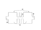
何れにしても、上述の様にして造った、図2に示す様な第二素板21には、続く第三工程でプレスによる打ち抜き加工(ピアス加工)を施して、図4に示す様な第三素板24とする。即ち、上記第三工程では、上記第二素板21の中央部に鼓形の透孔11を、前記厚肉部22とほぼ同じ幅で、且つ上記第二素板21の幅方向に関する位相をこの厚肉部22と一致させた状態で形成する。   In any case, the second base plate 21 produced as described above as shown in FIG. 2 is subjected to punching (piercing) by a press in the subsequent third step, as shown in FIG. The third base plate 24 is used. That is, in the third step, the drum-shaped through-hole 11 is formed in the central portion of the second base plate 21 so that the phase in the width direction of the second base plate 21 is approximately the same width as the thick portion 22. It forms in the state matched with this thick part 22.

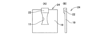
上述の様にして造った、上記第三素板24は、上記透孔11の周縁部に存在するバリを除去する為の面押し加工(チャンファリング)を施した後、続く第四工程で、上記主部19の周縁部の余分な部分を除去する切除加工(トリミング・カットオフ)を施し、図5に示す様な第四素板25とする。この第四素板25の形状は、既に前記係合部6aとなるべき連結部3aの肉厚が大きくなっている以外、前述の先発明に於ける第二素板12(図16)の形状とほぼ同じである。   The third base plate 24 manufactured as described above is subjected to a surface pressing process (chamfering) for removing burrs existing at the peripheral edge of the through hole 11, and then in a subsequent fourth step. Excision processing (trimming / cutoff) for removing an excess portion of the peripheral portion of the main portion 19 is performed to obtain a fourth base plate 25 as shown in FIG. The shape of the fourth base plate 25 is the same as the shape of the second base plate 12 (FIG. 16) in the above-described prior invention except that the thickness of the connecting portion 3a to be the engaging portion 6a is already large. Is almost the same.

以上の工程を行なう為のプレス加工装置の構造は、特に限定しないが、加工能率を高める面からは、図1に示した第一素板18を図5に示した第四素板25にまで加工する工程を、順送プレスにより行なう事が好ましい。複数の工程分を一体にした型を使用する順送プレスの場合には、工程の進行に伴う被加工物の送り量を少なくできる為、加工能率を向上させる事ができる。これに対して、後述する図6〜13に示した曲げ加工は、トランスファプレスにより行なう事が好ましい。各工程に使用する型を互いに別体とするトランスファプレスは、工程の進行に伴う被加工物の送り量が多くなる為、加工能率を高くする事が難しくなる代わりに、型の製造が容易となり、設備費の低廉化によるコスト低減を図れる。   The structure of the press working apparatus for performing the above steps is not particularly limited. From the aspect of improving the working efficiency, the first base plate 18 shown in FIG. 1 is extended to the fourth base plate 25 shown in FIG. The processing step is preferably performed by a progressive press. In the case of a progressive press using a die in which a plurality of processes are integrated, the amount of work to be processed accompanying the progress of the process can be reduced, so that the machining efficiency can be improved. On the other hand, it is preferable to perform the bending process shown in FIGS. A transfer press that separates the dies used in each process increases the feed rate of the workpiece as the process progresses, making it easier to manufacture the mold instead of increasing the machining efficiency. The cost can be reduced by lowering the equipment cost.

上述の様にして造った、上記第四素板25には、外周縁部に存在するバリを除去する為の面押し加工を施した後、この第四素板25を焼きなます焼鈍工程を施す。この第四素板25にこの様な焼鈍工程を施せば、上記厚肉部22を形成する為の押圧作業等に伴う加工硬化により硬くなった部分を軟化させると共に、この押圧作業等に伴って上記第四素板25内に生じた残留応力を除去できる。この為、続く工程で各側壁部2、2(図8〜13)の形成作業を容易に行なう事ができるだけでなく、折り曲げ部に亀裂等の損傷が発生するのを有効に防止できる。尚、上記第四素板25には、必要に応じ、上記焼鈍工程に加えて、友ずり(複数の第四素板同士の擦り合わせ)、バレル加工等を施して、焼鈍加工に伴って表面に生じたスケールを落とすと共に、縁部に残留しているバリを除去する。   The fourth base plate 25 made as described above is subjected to a surface pressing process for removing burrs existing on the outer peripheral edge portion, and then an annealing process for annealing the fourth base plate 25. Apply. If this fourth base plate 25 is subjected to such an annealing process, the hardened part due to work hardening accompanying the press work for forming the thick portion 22 is softened, and along with this press work etc. Residual stress generated in the fourth base plate 25 can be removed. For this reason, it is possible not only to easily form the side wall portions 2 and 2 (FIGS. 8 to 13) in subsequent steps, but also to effectively prevent the bent portion from being damaged such as cracks. In addition, in addition to the said annealing process, the said 4th base plate 25 is given a friend (rubbing of several 4th base plates), barrel processing, etc. as needed, and the surface accompanying annealing processing is carried out. In addition to dropping the scale generated in step 1, the burrs remaining at the edge are removed.

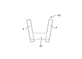
上述の様に、上記第四素板25を焼きなましたならば、前述した先発明の場合と同様に、この第四素板25の幅方向両端部を同方向に向け折り曲げて、互いに平行な1対の側壁部2、2を形成する。この折り曲げ加工は、前述した様に、図示しないトランスファプレスにより、図6〜7に示す様に行なう。この折り曲げ加工の際、折り曲げ位置(折り曲げの内周側隅角部)を、上記第四素板25の一部で前記透孔11を挟む2個所位置、即ち、図8に鎖線α´、α´で示す、この透孔11及び上記厚肉部22の幅方向両端縁にほぼ一致する位置とする。即ち、上記第四素板25の幅方向両端部を、上記両鎖線α´、α´を内周側角部として同方向に折り曲げて上記1対の側壁部2、2を形成し、図7に示す様な第一中間素材26とする。   As described above, if the fourth base plate 25 is annealed, both ends in the width direction of the fourth base plate 25 are bent in the same direction as in the case of the above-described previous invention, and the parallel ones are parallel to each other. A pair of side wall portions 2 and 2 are formed. As described above, this bending process is performed by a transfer press (not shown) as shown in FIGS. At the time of this bending process, bending positions (inner corners on the inner peripheral side of the bending) are two positions where the through holes 11 are sandwiched by a part of the fourth base plate 25, that is, chain lines α ′ and α in FIG. The positions of the through holes 11 and the thick portion 22 shown in FIG. That is, both ends in the width direction of the fourth base plate 25 are bent in the same direction with the two chain lines α ′ and α ′ as inner corners, thereby forming the pair of side wall portions 2 and 2. The first intermediate material 26 as shown in FIG.

この第一中間素材26を造る際に、上述の様に上記各側壁部2、2の形成する際の折り曲げ位置を、上記図8の鎖線α´、α´に示す様に、上記透孔11及び厚肉部22の幅方向両端縁にほぼ一致する位置としている為、上記各側壁部2、2の形成作業を容易に行なう事ができるだけでなく、折り曲げ部に亀裂等の損傷が発生するのを有効に防止できる。   When the first intermediate material 26 is manufactured, as shown above, the folding positions when the side wall portions 2 and 2 are formed are indicated by chain lines α ′ and α ′ in FIG. In addition, since the positions of the thick wall portions 22 are substantially coincident with both end edges in the width direction, the side wall portions 2 and 2 can be easily formed, and the bent portions are damaged such as cracks. Can be effectively prevented.

又、得られた上記第一中間素材26のうち、上記厚肉部22に対応する連結部3aの幅W3aは、図9(A)に示す様に、上記第一中間素材26を構成する1対の側壁部2、2同士の間隔D2 よりも大きく、この第一中間素材26の幅W26以下(W26≧W3a>D2 )となる。この様に連結部3aの幅W3aを1対の側壁部2、2同士の間隔D2 よりも大きくする事で、この連結部3aに形成した係合部6aの厚さ方向に大きな力が作用しても、この係合部6aに亀裂等の損傷が発生しにくくできる。これに対して、上記各側壁部2、2を曲げ加工した後、上記連結部3aに対応する部分に据え込み加工による増厚加工を施すと、図9(B)に示す様に、厚肉部22aの幅が1対の側壁部2、2同士の間隔D2 よりも小さくなる為、この厚肉部22aに形成した係合部に大きな力が加わった場合に、十分な耐久性を確保しにくくなる。
Of the obtained first intermediate material 26, the width W 3a of the connecting portion 3a corresponding to the thick portion 22 constitutes the first intermediate material 26 as shown in FIG. pair larger than the side wall portion 2,2 interval D 2 between the, become less width W 26 of the first intermediate material 26 (W 26 ≧ W 3a> D 2). By greater than the side wall portion 2,2 interval D 2 between the pair of width W 3a of such a connecting portion 3a, a large force in the thickness direction of the engaging portion 6a formed in the connecting portion 3a Even if it acts, damage such as cracks can hardly occur in the engaging portion 6a. On the other hand, when the side wall portions 2 and 2 are bent, and the portion corresponding to the connecting portion 3a is thickened by upsetting, as shown in FIG. since the width of the part 22a is smaller than the side wall portion 2,2 interval D 2 between the pair of, when a large force is applied to the engaging portion formed on the thick portion 22a, ensuring sufficient durability It becomes difficult to do.

上述の様な第一中間素材26の連結部3aには、図10〜11に示す様にして係合部6aを形成して第二中間素材27とすると共に、図12〜13に示す様にして第二の連結部4に第二の係合部7を形成して第三中間素材28とする。係合部6aを形成する作業と第二の係合部7を形成する作業との前後は問わない。又、上記1対の側壁部2、2の互いに整合する位置に円孔5、5(図14、20)を形成して、板金製ロッカーアームの最終形状とする。   In the connecting portion 3a of the first intermediate material 26 as described above, an engaging portion 6a is formed as shown in FIGS. 10 to 11 to form the second intermediate material 27, and as shown in FIGS. Thus, the second engaging portion 7 is formed in the second connecting portion 4 to form the third intermediate material 28. It does not matter before and after the operation of forming the engaging portion 6a and the operation of forming the second engaging portion 7. In addition, circular holes 5 and 5 (FIGS. 14 and 20) are formed at positions where the pair of side wall portions 2 and 2 are aligned with each other to form a final shape of the rocker arm made of sheet metal.

この様にして板金製ロッカーアームを最終形状に加工してから、この板金製ロッカーアームの表面を硬化させる為の、浸炭焼き入れ等の熱処理を行なう。そして、この熱処理の後、この板金製ロッカーアームに、表面の粒界酸化層を除去する為の処理工程を施す。この様な粒界酸化層を除去する為の処理は、ショットブラスト、バレル加工等、メディアの様な粒状物質を上記板金製ロッカーアームの表面に衝突させる方法により行なう。   After the sheet metal rocker arm is processed into the final shape in this manner, heat treatment such as carburizing and quenching is performed to harden the surface of the sheet metal rocker arm. Then, after this heat treatment, the sheet metal rocker arm is subjected to a treatment step for removing the surface grain boundary oxide layer. Such a process for removing the grain boundary oxide layer is performed by a method in which a granular material such as media collides against the surface of the rocker arm made of sheet metal, such as shot blasting or barrel processing.

この様に、板金製ロッカーアームの表面を硬化させる熱処理を行なった後、この板金製ロッカーアームに、表面の粒界酸化層を除去する為の処理工程を施せば、亀裂等の損傷の原因となる微小溝を除去して、上記板金製ロッカーアームの耐久性の向上を図れる。即ち、上記粒界酸化層の表面には微小溝が存在する為、この粒界酸化層をそのまま残した場合には、使用時にこの微小溝から亀裂等の損傷が発生し易くなる。そこで、上記処理により上記粒界酸化層と共に上記微小溝を除去して、上記損傷が発生しにくくする。尚、粒界酸化層を除去する為の処理を、ショットブラスト、バレル加工等、メディアの様な粒状物質を上記板金製ロッカーアームの表面に衝突させる方法により行なえば、この板金製ロッカーアームの表面層部分に残留圧縮応力を生じさせて、上記亀裂等の損傷の発生を、より一層有効に防止できる。   In this way, after performing a heat treatment to harden the surface of the rocker arm made of sheet metal, if the treatment process for removing the surface grain boundary oxide layer is performed on the rocker arm made of sheet metal, it may cause damage such as cracks. Thus, the durability of the rocker arm made of sheet metal can be improved. That is, since there are minute grooves on the surface of the grain boundary oxide layer, if the grain boundary oxide layer is left as it is, damage such as cracks is likely to occur from the minute grooves during use. Therefore, the micro-grooves are removed together with the grain boundary oxide layer by the above-described treatment, so that the damage is less likely to occur. If the process for removing the grain boundary oxide layer is carried out by a method such as shot blasting, barrel processing, or the like, where a granular material such as media collides with the surface of the rocker arm made of sheet metal, the surface of the rocker arm made of sheet metal. Residual compressive stress is generated in the layer portion, and the occurrence of damage such as cracks can be more effectively prevented.

この様にして造った板金製ロッカーアームには、使用時に弁体の基端部を突き当てる前記係合部6aの表面、及び使用時にラッシュアジャスタの先端部を突き当てる前記第二の係合部7の表面に、研摩等の必要な仕上加工を施した後、枢軸及びローラを組み付ける。尚、本発明の特徴である増厚方法によれば、バルブ係合部だけでなく、他の係合部も板厚を大きくできる。従って、ピボット係合部にねじ孔を設けると共にこのねじ孔にアジャストねじを螺合させる、メカニカルアジャスト型の板金製ロッカーアームで、上記ねじ孔とアジャストねじとの螺合長さを確保して、当該部分の強度を大きくできる。   The sheet metal rocker arm thus constructed has a surface of the engaging portion 6a that abuts the base end portion of the valve body when used, and the second engaging portion that abuts the tip end portion of the lash adjuster when used. The surface of 7 is subjected to necessary finishing such as polishing, and then the pivot and the roller are assembled. In addition, according to the thickening method which is the characteristic of this invention, not only a valve | bulb engagement part but another engagement part can enlarge plate | board thickness. Accordingly, a mechanical adjustment type sheet metal rocker arm that is provided with a screw hole in the pivot engaging portion and screwed into the screw hole, and secures the screwing length between the screw hole and the adjusting screw, The strength of the part can be increased.

本発明の実施の形態の1例の最初の工程で造られる第一素板を示しており、(A)は平面図、(B)は(A)の側方から見た図。The 1st base plate manufactured at the first process of one example of an embodiment of the invention is shown, (A) is a top view and (B) is a figure seen from the side of (A). 続く工程で造られる第二素板を示しており、(A)は平面図、(B)は(A)の側方から見た図。The 2nd base plate made in the process of the following is shown, (A) is a top view and (B) is a figure seen from the side of (A). 第二素板を加工する状態の別例を示す平面図。The top view which shows another example of the state which processes a 2nd base plate. 続く工程で造られる第三素板を示しており、(A)は平面図、(B)は(A)の側方から見た図。3A and 3B show a third base plate manufactured in a subsequent process, in which FIG. 5A is a plan view, and FIG. 5B is a view seen from the side of FIG. 続く工程で造られる第四素板を示しており、(A)は平面図、(B)は(A)の側方から見た図。4A and 4B show a fourth base plate manufactured in a subsequent process, in which FIG. 5A is a plan view, and FIG. 5B is a view seen from the side of FIG. 続く工程で第一中間素材を造る途中の状態を示す端面図。The end view which shows the state in the middle of making the 1st intermediate raw material in the subsequent process. 得られた第一中間素材を示しており、(A)は端面図、(B)は側面図。The obtained 1st intermediate material is shown, (A) is an end view, (B) is a side view. 第四素板から第一中間素材を造る際の折り曲げ位置を示す平面図。The top view which shows the bending position at the time of making a 1st intermediate material from a 4th base plate. 折り曲げ加工と増圧加工との前後が厚肉部の幅に及ぼす影響を示す為の、第一中間素材の端面図。The end view of the 1st intermediate material for showing the influence which the front and back of bending processing and pressurization processing have on the width of the thick part. 第二中間素材を得る途中の状態を示す端面図。The end view which shows the state in the middle of obtaining the 2nd intermediate material. 得られた第二中間素材を示す端面図。The end view which shows the obtained 2nd intermediate material. 第三中間素材を得る途中の状態を示す断面図。Sectional drawing which shows the state in the middle of obtaining a 3rd intermediate material. 得られた第三中間素材を示しており、(A)は断面図、(B)は側面図。The obtained 3rd intermediate material is shown, (A) is sectional drawing, (B) is a side view. 先発明に係る板金製ロッカーアームの斜視図。The perspective view of the sheet metal rocker arm concerning a prior invention. 先発明の第一工程により得られる第一素板を示しており、(A)は平面図、(B)は(A)のa−a断面図、(C)は(A)のb−b断面図、(D)は(A)のc−c断面図。The 1st base plate obtained by the 1st process of a prior invention is shown, (A) is a top view, (B) is aa sectional view of (A), (C) is bb of (A). Sectional drawing, (D) is cc sectional drawing of (A). 同第二工程により得られる第二素板を示しており、(A)は平面図、(B)は(A)のa−a断面図、(C)は(A)のb−b断面図、(D)は(A)のc−c断面図。The 2nd base plate obtained by the said 2nd process is shown, (A) is a top view, (B) is aa sectional drawing of (A), (C) is bb sectional drawing of (A). , (D) is cc sectional drawing of (A). 同第三工程により得られる第一中間素材を示しており、(A)は平面図、(B)は(A)のa−a断面図、(C)は(A)のb−b断面図、(D)は(A)のc−c断面図。The 1st intermediate material obtained by the said 3rd process is shown, (A) is a top view, (B) is aa sectional drawing of (A), (C) is bb sectional drawing of (A). , (D) is cc sectional drawing of (A). 同第四工程により得られる第二中間素材を示しており、(A)は平面図、(B)は(A)のa−a断面図、(C)は(A)のb−b断面図、(D)は(A)のc−c断面図。The 2nd intermediate material obtained by the 4th process is shown, (A) is a top view, (B) is an aa sectional view of (A), (C) is a bb sectional view of (A). , (D) is cc sectional drawing of (A). 同第五工程により造られる第三中間素材を示しており、(A)は平面図、(B)は(A)のa−a断面図、(C)は(A)のb−b断面図、(D)は(A)のc−c断面図。The 3rd intermediate material produced by the 5th process is shown, (A) is a top view, (B) is an aa sectional view of (A), (C) is a bb sectional view of (A). , (D) is cc sectional drawing of (A). 同第六工程を経て完成した板金製ロッカーアームを示しており、(A)は平面図、(B)は(A)のa−a断面図、(C)は(A)のb−b断面図、(D)は(A)のc−c断面図。The metal plate | board rocker arm completed through the said 6th process is shown, (A) is a top view, (B) is aa sectional drawing of (A), (C) is bb sectional drawing of (A). The figure and (D) are cc sectional views of (A).

符号の説明Explanation of symbols

1 板金製ロッカーアーム
2 側壁部
3、3a 連結部
4 第二の連結部
5 円孔
6、6a 係合部
7 第二の係合部
8 第一素板
9 基部
10 翼状部
11 透孔
12 第二素板
13 舌状部
14 切り欠き部
15 湾曲部
16 第一中間素材
17 第二中間素材
18 第一素板
19 主部
20 突出部
21 第二素板
22、22a 厚肉部
23 連続部
24 第三素板
25 第四素板
26 第一中間素材
27 第二中間素材
28 第三中間素材
DESCRIPTION OF SYMBOLS 1 Sheet metal rocker arm 2 Side wall part 3, 3a Connection part 4 Second connection part 5 Circular hole 6, 6a Engagement part 7 Second engagement part 8 First base plate 9 Base part 10 Wing-like part 11 Through-hole 12 First Two base plates 13 Tongue portion 14 Notch portion 15 Curved portion 16 First intermediate material 17 Second intermediate material 18 First base plate 19 Main portion 20 Protruding portion 21 Second base plate 22, 22a Thick portion 23 Continuous portion 24 Third base plate 25 Fourth base plate 26 First intermediate material 27 Second intermediate material 28 Third intermediate material

Claims (1)

1枚の金属材を打ち抜き成形する事により、所定の外形及び透孔を有する素板を形成し、この素板にプレス加工に基づく曲げ加工を施す事により、互いにほぼ平行な1対の側壁部とこれら両側壁部の幅方向一端縁同士を連結する連結部とを形成して成り、これら両側壁部の互いに整合する位置に形成した少なくとも1対の通孔と、上記連結部の一部に設けた、少なくとも1個の係合部とを備えた板金製ロッカーアームを製造する板金製ロッカーアームの製造方法であって、上記素板の一部で上記係合部となるべき部分に隣接する端縁から所定量分突出した突出部を、この係合部となるべき部分に向け、この所定量よりも少ない長さ分だけ上記素板の面方向に押圧する事により、この係合部となるべき部分の厚さを増大させて、一部が上記素板の他の部分よりも面方向に突出した厚肉部とした後、この厚肉部に係合部を形成する工程を有する板金製ロッカーアームの製造方法。 By punching and molding a single metal material, a base plate having a predetermined outer shape and through-holes is formed, and by bending the base plate based on press processing, a pair of side wall portions that are substantially parallel to each other And at least one pair of through-holes formed at positions where the both side wall portions are aligned with each other, and a part of the connecting portion. A sheet metal rocker arm manufacturing method for manufacturing a sheet metal rocker arm provided with at least one engaging portion provided adjacent to a portion of the base plate to be the engaging portion. By projecting the protrusion protruding from the edge by a predetermined amount toward the portion to be the engagement portion and pressing it in the surface direction of the base plate by a length less than the predetermined amount, Increase the thickness of the part that should be, and partly After a thick portion protruding in the surface direction than the other portions, the manufacturing method of the sheet metal rocker arm having a step of forming an engaging portion in the thick portion.
JP2006028710A 2006-02-06 2006-02-06 Sheet metal rocker arm manufacturing method Expired - Fee Related JP4127408B2 (en)

Priority Applications (1)

Application Number Priority Date Filing Date Title
JP2006028710A JP4127408B2 (en) 2006-02-06 2006-02-06 Sheet metal rocker arm manufacturing method

Applications Claiming Priority (1)

Application Number Priority Date Filing Date Title
JP2006028710A JP4127408B2 (en) 2006-02-06 2006-02-06 Sheet metal rocker arm manufacturing method

Related Parent Applications (1)

Application Number Title Priority Date Filing Date
JP2000103791A Division JP2001289011A (en) 2001-04-19 2000-04-05 Method of manufacturing plate rocker arm

Publications (3)

Publication Number Publication Date
JP2006136947A JP2006136947A (en) 2006-06-01
JP2006136947A5 JP2006136947A5 (en) 2006-07-13
JP4127408B2 true JP4127408B2 (en) 2008-07-30

Family

ID=36618076

Family Applications (1)

Application Number Title Priority Date Filing Date
JP2006028710A Expired - Fee Related JP4127408B2 (en) 2006-02-06 2006-02-06 Sheet metal rocker arm manufacturing method

Country Status (1)

Country Link
JP (1) JP4127408B2 (en)

Families Citing this family (2)

* Cited by examiner, † Cited by third party
Publication number Priority date Publication date Assignee Title
JP6561575B2 (en) * 2015-05-19 2019-08-21 日本製鉄株式会社 Manufacturing method of forged crankshaft
JP6561577B2 (en) * 2015-05-20 2019-08-21 日本製鉄株式会社 Manufacturing method of forged crankshaft

Also Published As

Publication number Publication date
JP2006136947A (en) 2006-06-01

Similar Documents

Publication Publication Date Title
AU2001248792B2 (en) Metal plate rocker arm and method of manufacturing the metal plate rocker arm
US6199527B1 (en) Sheet metal rocker arm, manufacturing method thereof, cam follower with said rocker arm, and assembling method thereof
JP6344485B2 (en) Manufacturing method of forged crankshaft
CN102548684B (en) Crankshaft production method and production apparatus
JP6024832B2 (en) Manufacturing method of forged crankshaft
JP6037049B2 (en) Manufacturing method of forged crankshaft
WO2015075924A1 (en) Production method for forged crank shaft
US7000582B2 (en) Rocker arm
JP4127408B2 (en) Sheet metal rocker arm manufacturing method
JP4155995B2 (en) Sheet metal rocker arm manufacturing method
JP2016007644A (en) Manufacturing method for forging crank shaft
WO2016159253A1 (en) Manufacturing method for forged crank shaft
JP4123252B2 (en) Sheet metal rocker arm manufacturing method
JP2001047179A (en) Manufacture of metal sheet rocker arm
JP4539381B2 (en) Sheet metal rocker arm manufacturing method
JP2000120411A (en) Sheet metal rocker arm and manufacture therefor
JP6380670B2 (en) Forging crankshaft manufacturing equipment
JP2000110522A (en) Sheet metal-made rocker arm
JP6550919B2 (en) Forging crankshaft manufacturing equipment
JP2000120411A5 (en)
JP2002276309A (en) Rocker arm
JP2004195500A (en) Manufacturing method of rocker arm
JP2010007675A (en) Manufacturing method for rocker arm made of sheet metal
JP2003343215A (en) Rocker arm and cam follower made of sheet metal

Legal Events

Date Code Title Description
A521 Written amendment

Free format text: JAPANESE INTERMEDIATE CODE: A523

Effective date: 20060413

A131 Notification of reasons for refusal

Free format text: JAPANESE INTERMEDIATE CODE: A131

Effective date: 20080212

TRDD Decision of grant or rejection written
A01 Written decision to grant a patent or to grant a registration (utility model)

Free format text: JAPANESE INTERMEDIATE CODE: A01

Effective date: 20080507

A01 Written decision to grant a patent or to grant a registration (utility model)

Free format text: JAPANESE INTERMEDIATE CODE: A01

A61 First payment of annual fees (during grant procedure)

Free format text: JAPANESE INTERMEDIATE CODE: A61

Effective date: 20080507

FPAY Renewal fee payment (event date is renewal date of database)

Free format text: PAYMENT UNTIL: 20110523

Year of fee payment: 3

R150 Certificate of patent or registration of utility model

Free format text: JAPANESE INTERMEDIATE CODE: R150

LAPS Cancellation because of no payment of annual fees