JP4125739B2 - Image encoding method, image decoding method and apparatus - Google Patents
Image encoding method, image decoding method and apparatus Download PDFInfo
- Publication number
- JP4125739B2 JP4125739B2 JP2005137767A JP2005137767A JP4125739B2 JP 4125739 B2 JP4125739 B2 JP 4125739B2 JP 2005137767 A JP2005137767 A JP 2005137767A JP 2005137767 A JP2005137767 A JP 2005137767A JP 4125739 B2 JP4125739 B2 JP 4125739B2
- Authority
- JP
- Japan
- Prior art keywords
- decoding
- information
- image
- image signal
- unit
- Prior art date
- Legal status (The legal status is an assumption and is not a legal conclusion. Google has not performed a legal analysis and makes no representation as to the accuracy of the status listed.)
- Expired - Lifetime
Links
Images


Landscapes
- Compression Or Coding Systems Of Tv Signals (AREA)
- Compression, Expansion, Code Conversion, And Decoders (AREA)
Description
本発明は、画像符号化方法及び画像復号化方法に関し、特に画像信号を効率良く記録・伝送するためのデータ圧縮に関わる符号化技術、復号化技術及びそれらの装置に関する。 The present invention relates to an image encoding method and an image decoding method, and more particularly to an encoding technique, a decoding technique, and their apparatuses related to data compression for efficiently recording and transmitting an image signal.
近年、音声、画像、その他のコンテンツを統合的に扱うマルチメディア時代を迎え、従来からの情報メディア、つまり新聞、雑誌、テレビ、ラジオ、電話等の情報を人に伝達する手段がマルチメディアの対象として取り上げられるようになってきた。一般に、マルチメディアとは、文字だけでなく、図形、音声、特に画像等を同時に関連づけて表すものをいうが、上記従来の情報メディアをマルチメディアの対象とするには、その情報をデジタル形式にして表すことが必須条件となる。 In recent years, the multimedia era of voice, image, and other contents has been integrated, and conventional information media, that is, means for transmitting information such as newspapers, magazines, televisions, radios, telephones, etc. to people are targeted for multimedia. It has come to be taken up as. In general, multimedia refers to not only characters but also figures, sounds, especially images, etc. that are associated with each other at the same time. To make the above-mentioned conventional information media a multimedia target, the information is converted into a digital format. It is an essential condition.
ところが、上記の各情報メディアの持つ情報量をデジタル情報量として見積もってみると、文字の場合1文字当たりの情報量は1〜2バイトであるのに対し、音声の場合は1秒当たり64Kbits(電話品質)、さらに、動画については1秒当たり100Mbits(現行テレビ受信品質)以上の情報量が必要となり、上記情報メディアでその膨大な情報をデジタル形式でそのまま扱うことは現実的ではない。例えば、テレビ電話は、64Kbps〜1.5Mbpsの伝送速度を持つサービス総合デジタル網(ISDN:Integrated Services Digital Network)によって、すでに実用化されているが、テレビやカメラの映像をそのままISDNで送ることは実用的とはいえない。 However, when the information amount of each information medium is estimated as a digital information amount, the information amount per character is 1 to 2 bytes in the case of characters, whereas 64 Kbits ( In addition, for a moving image, an information amount of 100 Mbits per second (current television reception quality) or more is required for a moving image, and it is not realistic to handle the enormous amount of information in the digital format as it is with the information media. For example, a video phone has already been put into practical use by an Integrated Services Digital Network (ISDN) having a transmission speed of 64 Kbps to 1.5 Mbps. Not practical.
そこで、必要となってくるのが情報の圧縮技術であり、例えば、テレビ電話の場合、ITU−T(国際電気通信連合 電気通信標準化部門)で勧告されたH.261やH.263規格の動画圧縮技術が用いられている。また、MPEG−1規格の情報圧縮技術によると、通常の音楽用CD(コンパクト・ディスク)に音声情報と共に画像情報を入れることも可能となる。 Therefore, what is required is information compression technology. For example, in the case of a videophone, H.264 recommended by ITU-T (International Telecommunication Union Telecommunication Standardization Sector). 261 and H.264. H.263 standard video compression technology is used. In addition, according to the information compression technology of the MPEG-1 standard, it is possible to put image information together with audio information on a normal music CD (compact disc).
ここで、MPEG(Moving Picture Experts Group)とは、動画像信号のデジタル圧縮の国際規格であり、MPEG−1は、動画像信号を1.5Mbpsのレートで伝送できるように、つまりテレビ信号の情報を約100分の1にまで圧縮する規格である。また、MPEG−1規格を対象とする伝送速度が、主として約1.5Mbpsに制限されていることから、さらなる高画質化の要求をみたすべく規格化されたMPEG−2では、動画像信号を2〜15MbpsのレートでTV放送品質のデータ伝送を可能にする。 Here, MPEG (Moving Picture Experts Group) is an international standard for digital compression of moving picture signals, and MPEG-1 is so that moving picture signals can be transmitted at a rate of 1.5 Mbps, that is, information on television signals. Is a standard that compresses up to about 1/100. In addition, since the transmission speed for the MPEG-1 standard is mainly limited to about 1.5 Mbps, MPEG-2 standardized to meet the demand for higher image quality requires 2 video signals. Enables TV broadcast quality data transmission at a rate of ~ 15 Mbps.
さらに現状では、MPEG−1、MPEG−2と標準化を進めてきた作業グループ(ISO/IEC JTC1/SC29/WG11)によって、より圧縮率が高いMPEG−4が規格化された。MPEG−4では、当初、低ビットレートで効率の高い符号化が可能になるだけでなく、伝送路誤りが発生しても主観的な画質劣化を小さくできる強力な誤り耐性技術も導入されている。 Furthermore, MPEG-4 with a higher compression rate has been standardized by a working group (ISO / IEC JTC1 / SC29 / WG11) that has been standardizing with MPEG-1 and MPEG-2. MPEG-4 initially introduced not only high-efficiency coding at a low bit rate, but also a powerful error resilience technology that can reduce subjective image quality degradation even if a transmission path error occurs. .
さて、H.263やMPEG−4等、従来の画像符号化では、画像信号に様々な信号変換・圧縮処理を行って画像信号を様々な種類の数値に変換し、変換された各数値の意味によって適切に選択した符号表に基づいた固定長符号化もしくは可変長符号化を行っている。一般に、符号化においては、生起頻度が高い符号には短い符号長の符号語を割り当て、生起頻度が低い符号には長い符号長の符号語を割り当てることで圧縮率を向上させている。信号変換・圧縮処理によって変換された数値は、その数値が表す意味によって数値の発生頻度が異なるわけであるから、それらの数値に対応する符号語が記載された符号表を適切に選択することで、画像符号化の圧縮率が向上することになる。従来の画像符号化に対応する従来の画像復号化では、画像符号化で使用した符号表と同じ符号表を使用して、正しい復号化を行なっている。 H. In conventional image coding such as H.263 and MPEG-4, various signal conversion / compression processes are performed on the image signal to convert the image signal into various types of numerical values, which are appropriately selected according to the meaning of each converted numerical value. The fixed length coding or variable length coding based on the code table is performed. In general, in coding, a compression rate is improved by assigning a codeword having a short code length to a code having a high occurrence frequency and assigning a codeword having a long code length to a code having a low occurrence frequency. The numerical values converted by the signal conversion / compression process differ in the frequency of occurrence depending on the meanings represented by the numerical values. Therefore, by appropriately selecting a code table in which codewords corresponding to those numerical values are described. Thus, the compression rate of image encoding is improved. In conventional image decoding corresponding to conventional image encoding, the same code table as that used in image encoding is used to perform correct decoding.
図17は、従来の画像符号化装置500における符号化機能に係る部分の機能ブロック図である。図17に示されるように、画像符号化装置500は、ヘッダ・フレーム符号化部501、シンタックス解析部502、固定長・可変長符号化部503及び符号表選択部504を備える。
ヘッダ・フレーム符号化部501は、動画像信号Vinを入力し、この動画像信号Vinから画像全体に共通する情報であるヘッダ部の情報及びフレーム毎の画像信号情報を作成する。
FIG. 17 is a functional block diagram of a portion related to an encoding function in a conventional
The header /
具体的には、ヘッダ・フレーム符号化部501は、ヘッダ部の情報として、その共通情報であるヘッダパラメータ(Inf_H、図示せず。)とそれを数値に変換したヘッダ符号値(InfVal_H)、及びヘッダ符号値の数値の意味を示すヘッダシンタックス構造信号(Stx_H)を生成し、このヘッダシンタックス構造信号(Stx_H)をシンタックス解析部502に出力し、ヘッダ符号値(InfVal_H)を固定長・可変長符号化部503に出力する。さらに、ヘッダ・フレーム符号化部501は、フレーム毎の画像信号情報として、各フレームの画像信号を符号化した結果得られる数値であるフレーム符号値(InfVal_F)、及びフレーム符号値の数値の意味を示すフレームシンタックス構造信号(Stx_F)を生成し、このフレームシンタックス構造信号(Stx_F)をシンタックス解析部502に出力し、フレーム符号値(InfVal_F)を固定長・可変長符号化部503に出力する。なお、図17においては、ヘッダ符号値(InfVal_H)とフレーム符号値(InfVal_F)をまとめて"InfVal_X"と記載し、ヘッダシンタックス構造信号(Stx_H)とフレームシンタックス構造信号(Stx_F)をまとめて"Stx_X"と記載している。
Specifically, the header /
シンタックス解析部502は、ヘッダシンタックス構造信号(Stx_H)又はフレームシンタックス構造信号(Stx_F)に基づいて、符号表選択信号(Sel_H又はSel_F)を生成し、符号表選択部504に出力する。すなわち、シンタックス解析部502は、ヘッダシンタックス構造信号又はフレームシンタックス構造信号が示す値に基づいて、複数の符号表から適切な符号表を選択するための符号表選択信号(例えば、Sel_H1〜Sel_H3、又はSel_F1〜Sel_F3)を生成する。なお、図17においては、符号表選択信号(Sel_H及びSel_F)をまとめて"Sel_X"と記載している。
The
固定長・可変長符号化部503は、上記のヘッダ符号値(InfVal_H)及びフレーム符号値(InfVal_F)に基づいて、画像符号化信号(Str)を構成する。具体的には、ヘッダ符号値(InfVal_H)を符号化の基本単位である単位ヘッダ符号値(Val_H:例えば、Val_H1〜Val_H3)に分解し、それらの単位ヘッダ符号値に基づいて符号表選択部504において符号表を選択してヘッダ符号語(Code_H)を得ると共に、ヘッダ符号値(InfVal_H)とヘッダ符号語(Code_H)とを組み合わせてヘッダストリーム(Str_H)を構成する。さらに、固定長・可変長符号化部503は、上記フレーム符号値(InfVal_F)を符号化の基本単位である単位フレーム符号値(Val_F:例えば、Val_F1〜Val_F3)に分解し、それらの単位フレーム符号語に基づいて符号表選択部504において符号表を選択してフレーム符号語(Code_F)を得ると共に、フレーム符号値(InfVal_F)とフレーム符号語(Code_F)とを組み合わせてフレームストリーム(Str_F)を構成する。さらにまた、固定長・可変長符号化部503は、ヘッダストリーム(Str_H)とフレームストリーム(Str_F)とを多重化し、画像符号化信号(Str)を構成する。なお、図17においては、単位ヘッダ符号値(Val_H)及び単位フレーム符号値(Val_F)をまとめて"Val_X"と記載し、ヘッダ符号語(Code_H)及びフレーム符号語(Code_F)をまとめて"Code_X"と記載している。
The fixed-length / variable-
符号表選択部504は、上記のように、符号表選択信号Sel_X及び単位ヘッダ符値又は単位フレーム符号値に基づいて符号表を選択し、その選択された符号表に従ってヘッダ符号語又はフレーム符号語を生成して固定長・可変長符号化部503に出力する。
As described above, the code
図18は、従来の画像符号化信号のストリーム構成を示す図である。画像符号化信号Strは、画像を構成する各フレームの画像信号情報が格納されるフレームデータFrmDataと各フレームに共通の情報であるシーケンスヘッダSeqHdrで構成される。シーケンスヘッダSeqHdrは、送受信間で同期をとるための同期信号SeqSync、各フレームの画像サイズSize及びフレームレートFrmRateの各情報で構成される。一方、フレームデータFrmDataは、フレームを構成するマクロブロック固有のデータであるマクロブロックデータMBと各マクロブロックで共通のデータであるフレームヘッダFrmHdrで構成される。フレームヘッダFrmHdrは、フレームの同期をとるための同期信号FrmSyncとフレームを表示する時刻を示すフレーム番号FrmNoで構成される。また、マクロブロックデータMBは、当該マクロブロックが符号化されているか否かを示す符号化フラグCod、各マクロブロックの符号化方法を示すマクロブロック符号化モードMode、動き補償を付加して符号化されている場合には、その動き量を表す動き情報MV及び各画素の符号化データである画素値データCoefで構成される。 FIG. 18 is a diagram showing a stream configuration of a conventional image encoded signal. The encoded image signal Str is composed of frame data FrmData in which image signal information of each frame constituting the image is stored and a sequence header SeqHdr that is information common to each frame. The sequence header SeqHdr includes information on a synchronization signal SeqSync for synchronization between transmission and reception, image size Size of each frame, and frame rate FrmRate. On the other hand, the frame data FrmData is composed of macroblock data MB which is data unique to the macroblocks constituting the frame and a frame header FrmHdr which is data common to each macroblock. The frame header FrmHdr includes a synchronization signal FrmSync for synchronizing the frame and a frame number FrmNo indicating the time for displaying the frame. The macroblock data MB is encoded with a coding flag Cod indicating whether or not the macroblock is encoded, a macroblock encoding mode Mode indicating the encoding method of each macroblock, and motion compensation. In the case where it is set, it is composed of motion information MV representing the amount of motion and pixel value data Coef which is encoded data of each pixel.
図19は、従来の画像復号化装置600における復号化機能に係る部分の機能ブロック図である。同図において、上記図17の従来の画像符号化装置500における機能ブロック図と同じ機能を有する構成及び同じ意味の信号には同じ符番を付し、その説明は省略する。
FIG. 19 is a functional block diagram of a portion related to a decoding function in the conventional
固定長・可変長復号化部601は、画像符号化信号Strをヘッダストリーム(Str_H)とフレームストリーム(Str_F)に分離する。さらに、固定長・可変長復号化部601は、ヘッダストリーム(Str_H)を復号化の基本単位であるヘッダ符号語Code_H(例えば、Code_H1〜Code_H3)に分解し、符号表選択部602においてヘッダ符号語Code_Hに対応する単位ヘッダ符号値(Val_H)を得て、それらを組み合わせてヘッダ符号値(InfVal_H)を構成する。さらにまた、固定長・可変長復号化部601は、上記ヘッダストリーム(Str_H)の場合と同様に、フレームストリーム(Str_F)に対しても、復号化の基本単位であるフレーム符号語Code_F(例えば、Code_F1〜Code_F3)に分解し、符号表選択部602においてフレーム符号語Code_Fに対応する単位フレーム符号値Val_Fを得て、それを組み合わせてフレーム符号値(InfVal_F)を構成する。
The fixed length / variable
ヘッダ・フレーム復号化部603は、ヘッダ符号値(InfVal_H)を復号してヘッダ部の情報を復元し、その共通情報であるヘッダパラメータ(Inf_H、図示せず。)と後続のヘッダ符号値の特徴を示すヘッダシンタックス構造信号(Stx_H)を出力する。ここで、ヘッダシンタックス構造信号(Stx_H)は、ヘッダ部の次の符号語を復号化するために必要な次の符号語の意味を示す情報である。さらに、ヘッダ・フレーム復号化部603は、上記ヘッダ符号値(InfVal_H)の場合と同様に、各フレームのフレーム符号値InfVal_Fを復元し、その符号値の意味を示すフレームシンタックス構造信号Stx_Fと復号動画像信号Voutとを出力する。
The header /
シンタックス解析部604は、ヘッダシンタックス構造信号(Stx_H)によってヘッダ部の次の符号語を復号化するために符号表選択部602の出力を切り替えるための符号表選択信号(Sel_H)を出力する。すなわち、シンタックス解析部604は、ヘッダシンタックス構造信号(Stx_H)が示す値によって、複数の符号表から適切な符号表を切り替えるための符号表選択信号(Sel_H)を生成する。さらに、シンタックス解析部604は、上記ヘッダシンタックス構造信号(Str_H)の場合と同様に、フレームシンタックス構造信号(Stx_F)によって符号表選択信号(Sel_F)を出力する。
The
ここで、フレームシンタックス構造信号Stx_Fは、次の符号語を復号化するために必要な次の符号語の特徴を示す情報である。シンタックス解析部604は、フレームシンタックス構造信号Stx_Fによって次の符号語を復号化するために符号表選択部の出力を切り替えるための符号表選択信号Sel_Fを出力する。すなわち、シンタックス解析部604は、フレームシンタックス構造信号Stx_Fが示す値に基づいて、複数の符号表から適切な符号表を切り替えるための符号表選択信号Sel_Fを生成する。なお、図19においても上記図17と同様に、ヘッダ部の情報とフレーム毎の画像信号情報に関する信号の共通の総称として"InfVal_X"、"Stx_X"、"Sel_X"、"Val_X"、"Code_X"を使用している。
Here, the frame syntax structure signal Stx_F is information indicating the characteristics of the next codeword necessary for decoding the next codeword. The
なお、上記図17及び図19のヘッダストリームStr_Hは、図18の従来の画像符号化信号のストリーム構成のシーケンスヘッダSeqHdr、もしくはシーケンスヘッダSeqHdrとフレームヘッダFrmHdrとを合わせたものに対応し、フレームストリームStr_Fは、それぞれフレームデータFrmData、もしくはマクロブロックデータMBに対応する。 The header stream Str_H in FIGS. 17 and 19 corresponds to the sequence header SeqHdr of the stream configuration of the conventional image encoded signal in FIG. 18 or a combination of the sequence header SeqHdr and the frame header FrmHdr. Str_F corresponds to frame data FrmData or macroblock data MB, respectively.
しかし、このような従来の画像符号化装置及び従来の画像復号化装置には、圧縮率を高めるためには複数の符号表が必要であり、
(1)符号表を切り替えるための処理が複雑になる。
という課題がある。高性能・大容量のコンピュータで符号化・復号化を行なう際にはこれらの課題は特に問題とならないが、携帯端末などの小メモリ・低演算能力での実現が困難になり、問題となる。特に、従来の画像符号化装置及び従来の画像復号化装置では、シンタックス構造信号(Stx_X)によって、符号表選択部504、602で頻繁に符号表が切り替えられるため、符号表の切替処理が複雑になるおそれがあった。
However, such a conventional image encoding device and a conventional image decoding device require a plurality of code tables in order to increase the compression rate,
(1) Processing for switching code tables is complicated.
There is a problem. These problems are not particularly problematic when encoding / decoding is performed on a high-performance, large-capacity computer, but it becomes difficult to realize with a small memory and a low computing capacity of a portable terminal or the like. In particular, in the conventional image encoding device and the conventional image decoding device, the code table is frequently switched by the code
また、可変長符号化には、復号が比較的容易な符号表を用いて符号化するハフマン符号化と、符号化・復号化処理が複雑であるが圧縮効率の高い算術符号化の2通りがある。算術符号化も一種の可変長符号化であり、算術符号化の符号化・復号化で使用する確率が符号表に相当する。しかしながら、両者が同じストリーム中に複雑に混在する場合には、符号化及び復号化の過程でハフマン符号化と算術符号化号表を切り替えるための処理が非常に複雑であるため、上記の携帯端末などにおいては実現が困難であるという問題がある。 In addition, variable length coding includes two types of coding: Huffman coding that uses a code table that is relatively easy to decode, and arithmetic coding that is complicated in coding and decoding processing but has high compression efficiency. is there. Arithmetic coding is also a kind of variable length coding, and the probability of use in coding / decoding of arithmetic coding corresponds to a code table. However, when both are mixed together in the same stream, the process for switching between the Huffman coding and the arithmetic coding table in the process of encoding and decoding is very complicated. In such a case, there is a problem that it is difficult to realize.
そこで、本発明は、上記課題に鑑みてなされたものであり、携帯端末などのように小メモリ・低演算能力であっても、従来と同等のデータ圧縮を可能とする画像符号化方法及び画像復号化方法を提供することを目的とする。 Therefore, the present invention has been made in view of the above problems, and an image encoding method and an image that enable data compression equivalent to the conventional one even with a small memory and a low computing capacity such as a portable terminal. An object is to provide a decryption method.
上記目的を達成するために、本発明に係る画像符号化方法は、フレーム単位の画像信号を含む情報を符号化するための画像符号化方法であって、前記符号化の対象となる情報には、前記画像信号全体の特徴に関する情報と前記フレーム単位の画像信号に係る情報とが含まれ、前記画像信号全体の特徴に関する情報に対しては、複数の符号化方式を利用して符号化を行なう複数符号化ステップと、前記フレーム単位の画像信号に係る情報に対しては、各フレーム共通の符号化方式を利用して符号化を行なう共通符号化ステップと、前記符号化された画像信号全体の特徴に関する情報と前記符号化されたフレーム単位の画像信号に係る情報とを多重して符号化を行なう多重符号化ステップとを含むことを特徴とする。 In order to achieve the above object, an image encoding method according to the present invention is an image encoding method for encoding information including an image signal in frame units, and the information to be encoded includes , Information on the characteristics of the entire image signal and information on the image signal in frame units are included, and the information on the characteristics of the entire image signal is encoded using a plurality of encoding methods. A plurality of encoding steps, and information related to the image signal in units of frames are encoded using a common encoding method for each frame, and the entire encoded image signal is encoded. And a multiplex encoding step of performing encoding by multiplexing information relating to the feature and information relating to the encoded image signal in frame units.
さらに、上記目的を達成するために、本発明に係る画像復号化方法は、所定単位の画像信号を含む情報を復号化するための画像復号化方法であって、前記復号化の対象となる情報には、前記画像信号全体に共通する情報と前記所定単位の画像信号に係る情報とが含まれ、前記画像信号全体に共通する情報に対しては、複数の復号化方式を利用して復号化を行なう複数復号化ステップと、前記所定単位の画像信号に係る情報に対しては、各所定単位で共通する、単一の可変長復号化方式又は算術復号化方式を利用して復号化を行なう共通復号化ステップとを含むことを特徴とする。 Further, in order to achieve the above object, an image decoding method according to the present invention is an image decoding method for decoding information including an image signal of a predetermined unit, the information to be decoded. Includes information common to the entire image signal and information related to the image signal of the predetermined unit, and the information common to the entire image signal is decoded using a plurality of decoding methods. A plurality of decoding steps to be performed and information related to the image signal of the predetermined unit are decoded using a single variable length decoding method or arithmetic decoding method common to each predetermined unit. And a common decoding step.
以上のように、本発明に係る画像符号化方法及び画像復号化方法によれば、画像全体に関わる情報を符号化する場合は従来と同様に複数の符号表を用いるが、個別の画像情報については単一の符号化方式/復号化方式(符号表)を用いるので、圧縮率をほとんど低下させることなく、個別の画像情報の符号化又は復号化の処理が簡潔に実現でき、コストダウン等を図ることが可能となる為、その実用的価値は高い。 As described above, according to the image encoding method and the image decoding method according to the present invention, when encoding information related to the entire image, a plurality of code tables are used as in the past, but for individual image information Uses a single encoding method / decoding method (code table), so that encoding or decoding of individual image information can be realized succinctly with almost no reduction in compression rate, thereby reducing costs, etc. Since it can be planned, its practical value is high.
以下、本発明に係る実施の形態について、図1から図16を用いて説明する。
(実施の形態1)
図1は、本実施の形態の画像符号化装置10における符号化機能に係る部分の機能ブロック図である。図1において、上記図17に示した従来の画像符号化装置500における信号と同じ動作に係る信号については同じ記号を付し、その説明は省略する。
Embodiments according to the present invention will be described below with reference to FIGS.
(Embodiment 1)
FIG. 1 is a functional block diagram of a portion related to an encoding function in the
本実施の形態に係る画像符号化装置10は、画像信号全体に共通する情報であるヘッダ部には複数の符号化方式が適用され、フレーム単位の画像信号に係る情報には単一の符号化方式が適用されることを特徴としている。
In the
ここで、本明細書においてはフレームで説明しているが、インターレス画像信号の場合はフレームの代りにフィールドとしてもよい。 Here, in this specification, the frame is described, but in the case of an interlaced image signal, a field may be used instead of the frame.
なお、画像信号全体に共通する情報であるヘッダ部の情報を作成し符号化するための構成及びその動作は、上記図17の従来の画像符号化装置500の場合と全く同じである。
The configuration and operation for creating and encoding the header information, which is information common to the entire image signal, and the operation thereof are exactly the same as those of the conventional
図1に示されるように、画像符号化装置10は、上記従来の画像符号化装置500に比べ、新たにフレーム符号化部13及び可変長符号化部16を備える。なお、多重化部17は、上記従来の画像符号化装置500の固定長・可変長符号化部503における機能のうち、一部の機能を抜き出したものである。
As shown in FIG. 1, the
フレーム符号化部13は、動画像信号Vinから個別の画像信号情報を作成する部分であり、ヘッダパラメータInf_Hを参照して各フレームの画像信号情報を符号化した結果得られる数値であるフレーム符号値InfVal_Fを可変長符号化部16に出力する。
The
可変長符号化部16は、フレーム符号値InfVal_Fを符号化の基本単位である単位フレーム符号値Val_Fに分解し、符号表16aのみを使用して単位フレーム符号値Val_Fをフレーム符号語Code_Fに変換し、変換されたフレーム符号語を組み合わせてフレームストリームStr_Fを構成する。これにより、フレーム単位の画像信号に係る情報は、従来のようにシンタックスに応じて符号化方式を切り替えることもなく、全フレームにおいて共通で単一の符号化方式が適用される。
The variable
多重化部17は、ヘッダストリームStr_HとフレームストリームStr_Fとを多重化し、画像符号化信号Strを構成する。
The multiplexing
図2は、上記図1に示した画像符号化装置10における機能ブロック図で符号化された画像符号化信号Strのストリーム構成図である。図2に示されるように、本ストリームは、シーケンスヘッダSeqHdrと複数のフレームデータFrmDataから構成されている。この場合、シーケンスヘッダSeqHdrは、画像信号全体に共通する情報であり、フレームデータFrmDataは、符号表16aのみを用いて符号化されたデータである。
FIG. 2 is a stream configuration diagram of the image encoded signal Str encoded by the functional block diagram in the
なお、シーケンスヘッダSeqHdrとフレームデータFrmDataとは同じストリーム内で連続して送信する必要は必ずしもなく、復号化装置側で先にシーケンスヘッダSeqHdrを認識できるように制御すれば、それぞれ異なるストリームで送信してもよい。 Note that the sequence header SeqHdr and the frame data FrmData do not necessarily have to be transmitted continuously in the same stream, and if the decoding device side controls the sequence header SeqHdr first, the sequence header SeqHdr and the frame data FrmData are transmitted in different streams. May be.
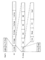
図3は、上記図2におけるフレームデータのデータ構成図である。
図3(a)は、一般的なフレームデータFrmDataのデータ構成図である。この場合、フレームデータFrmDataのフレームヘッダFrmHdrを画像信号全体に共通する情報として複数の符号化方式(符号表)で符号化を行ない、マクロブロックデータMBを単一の符号化方式(例えば、符号表16aのみ)で符号化を行なう場合の例である。この場合、符号化・復号化でストリームの大部分を占めるマクロブロックデータMBを単一の符号化方式(符号表16aのみ)で符号化を行なうため、従来は必要であった符号化方式(符号表)を頻繁に切り替える処理が不要になり、従来と同等の機能を有する画像符号化装置を簡素化して実現することが可能となる。
FIG. 3 is a data configuration diagram of the frame data in FIG.
FIG. 3A is a data configuration diagram of general frame data FrmData. In this case, the frame header FrmHdr of the frame data FrmData is encoded by a plurality of encoding methods (code tables) as information common to the entire image signal, and the macroblock data MB is encoded by a single encoding method (for example, the code table). 16a only) is an example of encoding. In this case, since the macroblock data MB that occupies most of the stream in encoding / decoding is encoded by a single encoding method (only the code table 16a), the encoding method (code Therefore, it is possible to simplify and realize an image encoding device having a function equivalent to that of the prior art.
なお、フレームヘッダFrmHdrとマクロブロックデータMBとは同じストリーム内で連続して送信する必要は必ずしもない。復号化装置側で先にフレームヘッダFrmHdrを認識できるように制御すれば、同じストリーム内で不連続な状態で送信してもよいし、それぞれ異なるストリームで送信してもよい。 The frame header FrmHdr and the macroblock data MB need not be transmitted continuously in the same stream. If control is performed so that the decoding apparatus can recognize the frame header FrmHdr first, it may be transmitted in a discontinuous state within the same stream, or may be transmitted in different streams.
なお、図3(a)に示すストリーム構成では、フレームデータFrmDataのフレームヘッダFrmHdrを画像信号全体に共通する情報としたが、MPEG−1やMPEG−2のスライス構造、MPEG−4のビデオパケット構造のように、さらにマクロブロックを複数集めて1つのフレームを構成し、そのマクロブロックの集合体の先頭に、さらに同期信号などの共通な情報(ヘッダ)を配置した場合には、そのマクロブロックの集合体のヘッダを画像信号全体に共通する情報とし、そのヘッダ以外の画像データを単一の符号表16aで符号化することとしてもよい。このマクロブロックの集合体で構成されるフレームは、スライス(Slice)と称される。 In the stream configuration shown in FIG. 3A, the frame header FrmHdr of the frame data FrmData is information common to the entire image signal. However, the MPEG-1 and MPEG-2 slice structure and the MPEG-4 video packet structure are used. When a plurality of macroblocks are collected to form one frame and common information (header) such as a synchronization signal is further arranged at the head of the macroblock aggregate, the macroblock The header of the aggregate may be information common to the entire image signal, and image data other than the header may be encoded with a single code table 16a. A frame composed of the aggregate of macroblocks is called a slice.
図3(b)は、上記のスライス構造のフレームデータのデータ構成図である。スライスヘッダSliceHdrを画像信号全体に共通する情報とし、複数の符号表で符号化を行ない、各スライスSliceのマクロブロックデータMBを単一の符号表16aで符号化を行なう。なお、スライスヘッダSliceHdrとマクロブロックデータMBとは同じストリーム内で連続して送信する必要は必ずしもない。復号化装置側で先にスライスヘッダSliceHdrを認識できるように制御すれば、同じストリーム内で不連続な状態で送信してもよいし、それぞれ異なるストリームで送信してもよい。 FIG. 3B is a data configuration diagram of the frame data having the above slice structure. The slice header SliceHdr is information common to the entire image signal, encoding is performed using a plurality of code tables, and the macro block data MB of each slice Slice is encoded using a single code table 16a. Note that the slice header SliceHdr and the macroblock data MB are not necessarily transmitted continuously in the same stream. If control is performed so that the decoding header can recognize the slice header SliceHdr first, it may be transmitted in a discontinuous state within the same stream, or may be transmitted in different streams.
図4は、本実施の形態において使用する符号表の一例である。図4(a)は、画像符号化装置10において可変長符号化を行なう際に使用する符号表の一例である。図4(a)に示されるように、発生頻度が高いデータ「0」〜「2」については、対応する符号語の符号長が短く、発生頻度が低い「3」〜「6」については、対応する符号語の符号長が長くなっている。
FIG. 4 is an example of a code table used in the present embodiment. FIG. 4A is an example of a code table used when variable length coding is performed in the
また、図4(b)は、画像符号化装置10において固定長符号化を行なう際に使用する符号表の一例である。図4(b)に示されるように、各データに対応する符号語の語長は一定であるが、画像符号化装置10内の最大フレームメモリ数が大きくなるに従って、符号語の符号長が長くなっている。
FIG. 4B is an example of a code table used when fixed-length encoding is performed in the
図5は、本実施の形態の画像復号化装置20における復号化機能に係る部分の機能ブロック図である。画像復号化装置20は、上記の画像符号化装置10によって符号化された画像符号化信号Strを復号化して復号動画像信号Voutを出力する。図5において、上記図19の従来の画像復号化装置600における信号と同じ動作に係る信号は同じ記号を付し、その説明は省略する。
FIG. 5 is a functional block diagram of a portion related to a decoding function in the
なお、画像信号全体に共通する情報であるヘッダ部の情報を復号化するための構成及びその動作は、上記図19の従来の画像復号化装置600の場合と同じである。
The configuration for decoding the header information, which is information common to the entire image signal, and the operation thereof are the same as those of the conventional
分離部21は、画像符号化信号Strを入力し、ヘッダストリームStr_HとフレームストリームStrFに分離する。可変長復号化部23は、フレームストリームStr_Fを構成するフレーム符号語Code_Fを符号表16aのみを使用してフレーム符号値Val_Fに変換し、単位フレーム符号値Val_Fから符号化された信号の数値であるフレーム符号値InfVal_Fを構成する。フレーム復号化部27は、画像信号全体に共通する情報であるヘッダパラメータInf_Hを参照して、フレーム符号値InfVal_Fを復号化し、復号後の動画像信号Voutを出力する。
The
以上のようにして、画像信号全体に共通する情報であるヘッダ部の情報以外の情報については、単一の符号表16aのみで復号化を可能としているため、従来は必要であった復号化方式(符号表)を頻繁に切り替える処理が不要になり、同等の機能を有する画像復号化装置を簡素化して実現することが可能となる。 As described above, since the information other than the header information, which is information common to the entire image signal, can be decoded only by the single code table 16a, the decoding method that has been necessary in the past is used. A process of frequently switching (code table) is not required, and an image decoding apparatus having an equivalent function can be simplified and realized.
なお、画像信号全体に共通する情報であるヘッダ部の情報とは、上記図2の画像符号化信号のストリーム構成におけるシーケンスヘッダSeqHdrや図3(a)のフレームデータFrmDataのフレームヘッダFrmHdrである。上記の画像符号化装置10の場合と同様に、マクロブロックデータMBを単一の符号表23aで復号化してもよい。さらに、上記の画像符号化装置10の場合と同様に、画像符号化信号のストリーム構成がスライス構造を有する場合は、スライスヘッダSliceHdrを画像信号全体に共通する情報とし、スライスヘッダ以外の情報を単一の符号表23aで復号化してもよい。
The header information, which is information common to the entire image signal, is the sequence header SeqHdr in the stream configuration of the image encoded signal in FIG. 2 and the frame header FrmHdr of the frame data FrmData in FIG. Similarly to the case of the
次に、上記のように構成された画像符号化装置10の動作について説明する。
図6は、画像符号化装置10の符号化処理の流れを示すフローチャートである。
Next, the operation of the
FIG. 6 is a flowchart showing the flow of the encoding process of the
最初に、ヘッダ情報作成部11に動画像信号Vinが入力されると(S61)、ヘッダシンタックス構造信号Stx_Hに基づいてヘッダ符号値InfoVal_Hを符号化する符号表が選択される(S63)。ヘッダ情報作成部11及び固定長・可変長符号化部15は、従来と同様の方法で、動画像信号Vinに基づいてヘッダ部の情報を作成し、分解された単位ヘッダ符号値(Val_H)に従って符号表を選択してその符号化を行なって(S64〜S66)、ヘッダストリームを構成する(S67)。
First, when the moving image signal Vin is input to the header information creation unit 11 (S61), a code table for encoding the header code value InfoVal_H is selected based on the header syntax structure signal Stx_H (S63). The header
一方、フレーム符号化部13は、動画像信号Vinを取得すると(S61)、ヘッダ部の情報以外の情報について、符号表16aのみを用いて符号化を行なって(S68)、フレームストリームを構成する(S69)。
On the other hand, when the
多重化部17は、ヘッダストリームとフレームストリームを多重化して画像符号化信号を構成する(S70)。
The multiplexing
以上のように、本実施の形態における画像符号化装置及び画像復号化装置によれば、符号化処理や復号化処理の大部分を占めるマクロブロックデータを単一の符号表を用いて符号化及び復号化を行なうため、従来は必要であった符号表を頻繁に切り替える処理が不要になり、従来と同等の機能を有する画像符号化装置を簡素化して実現することが可能となる。 As described above, according to the image encoding device and the image decoding device in the present embodiment, the macroblock data that occupies most of the encoding process and the decoding process are encoded and encoded using a single code table. Since decoding is performed, it is not necessary to frequently switch a code table that has been necessary in the past, and it is possible to simplify and realize an image coding apparatus having a function equivalent to that in the past.
(実施の形態2)
図7は、本実施の形態の画像符号化装置30における符号化機能に係る機能ブロック図である。図7において、上記図1の画像符号化装置10における機能ブロック図と同じ機能の構成及び同じ動作に係る信号は同じ記号を付し、その説明は省略する。
(Embodiment 2)
FIG. 7 is a functional block diagram relating to the encoding function in the
図7の画像符号化装置30と上記図1の画像符号化装置10との違いについて述べる。上記画像符号化装置10が画像信号全体に共通する情報であるヘッダ部の情報を作成する部分は、複数の符号表の中から適切な符号表を選択して符号化を行ない、その他の個別の画像信号情報については1つの符号表を用いて符号化を行なった。一方、本画像符号化装置30は、画像信号全体に共通する情報であるヘッダ部の情報の符号化を固定長符号化方式もしくは符号表を用いる通常の可変長符号化(ハフマン符号化)方式で符号化を行ない、その他の個別の画像信号情報は算術符号化のみで符号化する。
Differences between the
算術符号化は符号化・復号化の処理はハフマン符号化等の符号表を用いる通常の可変長符号化と比べてやや複雑であるが、圧縮率が向上することが知られている。従って、復号過程で特に重要且つ多種多様なヘッダ情報を通常の可変長符号化することで、フレームデータがどのような復号化をすべきであるか、迅速に判断することができる。算術符号化は伝送誤り等に弱いため、重要なデータであるヘッダ情報を通常の可変長符号化で符号化することは、誤り耐性向上にも大きな効果がある。
また、算術符号化と通常の可変長符号化を切り替える際には、特に処理が複雑であり、また算術符号化から通常の可変長符号化に切り替えるためには冗長なビット数が必要であることから、頻繁に算術符号化と通常の可変長符号化を切り替えることは得策では無い。
In arithmetic coding, encoding / decoding processing is slightly more complicated than normal variable length coding using a code table such as Huffman coding, but it is known that the compression rate is improved. Therefore, it is possible to quickly determine what kind of decoding the frame data should be performed by performing normal variable-length coding on a variety of header information that is particularly important in the decoding process. Since arithmetic coding is vulnerable to transmission errors and the like, encoding header information, which is important data, with normal variable-length coding has a great effect on improving error tolerance.
Also, when switching between arithmetic coding and normal variable length coding, the processing is particularly complicated, and a redundant number of bits is required to switch from arithmetic coding to normal variable length coding. Therefore, it is not a good idea to frequently switch between arithmetic coding and normal variable length coding.
シンタックス解析部12は、ヘッダシンタックス構造信号Stx_Hによって符号化選択部31の出力を切り替える符号化選択信号SelEncを符号化選択部31に出力する。
The
符号化選択部31は、固定長符号化方式もしくは可変長符号化方式の一方を符号化選択信号SelEncによって選択し、選択された符号化方式に従って固定長符号化部32もしくは可変長符号化部33で符号化を行なってヘッダストリームStr_Hを構成し、多重化部17に出力する。
The
算術符号化部34は、フレーム符号値InfVal_FをヘッダパラメータInf_Hを参照して算術符号化を行ない、算術符号化したフレームスリームStr_Fを構成し、多重化部17に出力する。
The
多重化部17は、ヘッダストリームStr_HとフレームストリームStr_Fとを多重化し、画像符号化信号Strを構成する。
The multiplexing
以上のように、本実施の形態に係る画像符号化装置30により、画像信号全体に共通する情報であるヘッダ部の情報については、シンタックスに応じて符号化方式を切り替えるという符号化を行ない、個別の画像信号情報の符号化は算術符号化のみで符号化を行なうことにより、符号化効率を劣化させずに符号化方式の切替処理の簡素化を可能にする画像符号化装置が実現できる。
As described above, the
図8は、本実施の形態の画像復号化装置40における復号化機能に係る機能ブロック図である。なお、図8において、上記実施の形態1の画像復号化装置20における機能ブロック図と同じ機能の構成及び同じ動作に係る信号は同じ記号を付し、その説明は省略する。
FIG. 8 is a functional block diagram relating to the decoding function in the
図8の画像復号化装置40と上記実施の形態1の画像復号化装置20との違いについて述べる。、上記画像復号化装置20は画像信号全体に共通する情報であるヘッダ部の情報を復号化する場合は、複数の符号表の中から適切な符号表を選択して復号化を行なった。一方、その他の個別の画像信号情報は1つの符号表を用いて復号化を行なうのに対し、本画像復号化装置40は、画像信号全体に共通する情報であるヘッダ部の情報を復号化する場合は、固定長復号化方式もしくは符号表を用いる通常の可変長符号化(ハフマン符号化)の逆処理として復号化し、その他の個別の画像信号情報は算術符号化のみで復号化する。なお、図8の画像復号化装置40は、上記図7の画像符号化装置30によって符号化された画像符号化信号Strを復号化する装置である。
Differences between the
シンタックス解析部26は、ヘッダシンタックス構造信号Stx_Hによって復号化選択部41の出力を切り替える復号化選択信号SelDecを出力する。復号化選択部41は、固定長復号化方式もしくは可変長復号化方式の一方を復号化選択信号SelDecによって選択し、選択された復号化方式に従って固定長復号化部42もしくは可変長復号化部43で復号化したヘッダ符号値InfVal_Hをヘッダ情報復号部25に出力する。
The
算術復号化部44は、ヘッダパラメータInf_Hを参照してフレームストリームStr_Fを算術復号化し、算術復号化されたフレーム符号値InfVal_Fを構成する。フレーム復号化部27は、画像信号全体に共通する情報であるヘッダパラメータInf_Hを参照してフレーム符号値InfVal_Fを復号化し、復号動画像信号Voutを出力する。
The
以上のように、画像信号全体に共通する情報であるヘッダ部の情報はシンタックスに応じて切り替える効率の良い符号化を行ない、個別の画像信号情報は算術符号化のみで符号化することで、符号化効率を劣化させずに切替処理を簡素化にした画像復号化装置を実現することが可能となる。 As described above, the information of the header part, which is information common to the entire image signal, is encoded efficiently with switching according to the syntax, and the individual image signal information is encoded only by arithmetic coding. It is possible to realize an image decoding device that simplifies the switching process without degrading the encoding efficiency.
なお、上記の画像符号化装置10、30や画像復号化装置20、40以外にもヘッダ部の情報と個別の画像信号情報を分離させ、各々の情報の符号化や復号化を複数の符号表を用いることによって実現することも可能である。
In addition to the
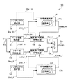
図9は、上記のように、ヘッダ部の情報と個別の画像信号情報とを分け、各々の情報の符号化を行なう画像符号化装置50の符号化機能に係る部分の機能ブロック図である。
FIG. 9 is a functional block diagram of a portion related to the encoding function of the
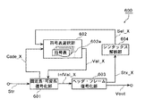
また、図10は、上記図9の画像符号化装置50に対応する画像復号化装置60の復号化機能に係る部分の機能ブロック図である。
FIG. 10 is a functional block diagram of a portion related to the decoding function of the
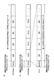
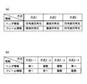
上記実施の形態1及び実施の形態2における符号化方法または復号化方法をまとめた表を図11に示す。図11(a)に示されるように、例えば方式1の通り、ヘッダ部の情報(図中では「ヘッダ情報」)とフレーム毎の画像信号に係る画像信号情報(図中では「フレーム情報」)の符号化を行なう場合は、従来の符号表を用いる符号化方式(以下、「符号表符号化」という。)と、算術符号化方式による符号化(以下、「算術符号化」という。)が考えられる。さらに、ヘッダ情報、フレーム情報それぞれを算術符号化(方式2)または符号表符号化(方式3)してもよい。
FIG. 11 shows a table summarizing the encoding method or the decoding method in the first embodiment and the second embodiment. As shown in FIG. 11A, for example, as in
さらに、図11(b)に示されるように、ヘッダ情報、フレーム情報共に符号表符号化を用いる場合は、「単一」の符号表を用いる場合と、「複数」の符号表を用いる符号化方式が考えられる。具体的には、ヘッダ情報、フレーム情報双方に対して単一(方式3−1)または複数の符号表(方式3−3)を用いた符号表を適用してもよい。さらに、ヘッダ情報には複数の符号表、フレーム情報には単一の符号表(方式3−2)、またはヘッダ情報には単一の符号表、フレーム情報には複数の符号表(方式3−4)の符号表を適用しても良い。 Furthermore, as shown in FIG. 11B, when code table coding is used for both header information and frame information, “single” code table is used, and “multiple” code table is used. A method is conceivable. Specifically, a code table using a single (method 3-1) or a plurality of code tables (method 3-3) may be applied to both header information and frame information. Further, a plurality of code tables for header information, a single code table for frame information (method 3-2), or a single code table for header information, and a plurality of code tables for frame information (method 3- The code table of 4) may be applied.
なお、方式1においても、ヘッダ情報に単一の符号表、または複数の符号表を適用できることはいうまでもない。ここで、複数の符号表とは、画像信号全体に共通する情報であるヘッダ部、フレーム単位の画像信号に係る情報で各々独自に符号化方法が決められるため、予め適用される符号表の個数が限定されており、これにより符号表の切り替えが最低限に抑えられる。
Needless to say, even in the
実施の形態1及び実施の形態2における符号化方法または復号化方法では、画像全体に関わる情報については従来と同様に複数の符号化・復号化方法(符号表)を備えるが、フレーム毎の画像信号に係る個別の情報については共通の符号化・復号化方法を用いることに特徴がある。一般に、画像全体に関わる情報ではその情報を構成する各符号の符号語の発生頻度が大きく異なるために複数の符号化・復号化方法を準備しないと圧縮率が大きく低下する。一方、個別の情報については画像全体に関わる情報ほど符号語の発生頻度がそれほど変化しないので、共通の符号化・復号化方法を用いても圧縮率がそれほど低下しない。また、符号化・復号化で殆どの処理時間が画像全体に関わる情報でなく個別情報の処理に必要なことから、個別情報の符号化・復号化が、好ましくは、単一の符号化方法で簡単に実現できれば、装置の実現上大きな利点がある。特に、固定長符号化の方が可変長符号化よりも同期をとるための同期信号検出が容易であり、高圧縮の観点からは複数の符号化法が適しているという固定長符号化と可変長符号化の切り替えも含めた複数符号化方法の切り替えの利点と、符号化・復号化が単一の符号化方法で簡単に実現できるという単一符号化方法の利点とを比較し、後者の利点が大きい利用分野で有効と思われる。 The encoding method or decoding method according to the first and second embodiments includes a plurality of encoding / decoding methods (code tables) for information related to the entire image, as in the related art. The individual information related to the signal is characterized by using a common encoding / decoding method. In general, in the information relating to the entire image, the frequency of occurrence of the codeword of each code constituting the information is greatly different. Therefore, unless a plurality of encoding / decoding methods are prepared, the compression rate is greatly reduced. On the other hand, since the frequency of codewords does not change as much as the information related to the entire image for individual information, the compression rate does not decrease so much even if a common encoding / decoding method is used. In addition, since most of the processing time for encoding / decoding is necessary for processing of individual information rather than information related to the entire image, encoding / decoding of individual information is preferably performed by a single encoding method. If it can be realized easily, there is a great advantage in realizing the apparatus. In particular, fixed-length coding and variable-length coding are easier to detect synchronization signals for synchronization, and fixed-length coding and variable that multiple coding methods are suitable from the viewpoint of high compression. Compare the advantage of switching between multiple coding methods, including switching of long coding, with the advantage of a single coding method in which encoding and decoding can be easily realized with a single coding method. It seems to be effective in fields of use where there are significant advantages.
また、算術符号化も可変長符号化の一種であり、算術符号化は圧縮効率が高い反面、特に固定長符号化や一般の可変長符号化(ハフマン符号化)と切り替えて使用すると複雑な処理が必要なことから、個別の情報については単一符号化方法として算術符号化のみを使用し、画像全体に関わる情報では算術符号以外を使用することが好ましい。 Arithmetic coding is also a type of variable-length coding, and arithmetic coding is high in compression efficiency. However, it is complicated processing especially when switched to fixed-length coding or general variable-length coding (Huffman coding). Therefore, it is preferable to use only arithmetic coding as a single encoding method for individual information, and use information other than arithmetic code for information relating to the entire image.
(実施の形態3)
上記実施の形態1又は実施の形態2で示した画像符号化方法または画像復号化方法を実現するためのプログラムをフレキシブルディスク等のコンピュータが読み取り可能な記憶媒体に記録し、上記各実施の形態で示した処理をパソコン等のコンピュータシステムにおいて実現することも可能である。
(Embodiment 3)
A program for realizing the image encoding method or the image decoding method shown in the first embodiment or the second embodiment is recorded on a computer-readable storage medium such as a flexible disk, and the above embodiments are used. It is also possible to implement the processing shown in a computer system such as a personal computer.
図12は、上記実施の形態1及び実施の形態2において説明した画像符号化方法又は画像復号化方法を格納したフレキシブルディスク1201を用いて、コンピュータシステムにより実施する場合の説明図である。
FIG. 12 is an explanatory diagram when the computer system is used by using the
図12(a)は、記録媒体のフレキシブルディスク1201の物理フォーマットの例を示している。図12(b)は、フレキシブルディスクを正面からみた外観図、断面構造図、及びフレキシブルディスクを示し、フレキシブルディスク1201はケース1202内に内蔵され、当該ディスクの表面には、同心円状に外周から内周に向かって複数のトラックが形成され、各トラックは角度方向に16のセクタに分割されている。従って、上記プログラムを格納したフレキシブルディスク1201では、ディスク上に割り当てられた領域に、上記画像符号化方法又は画像復号化方法を実現するプログラムが記録されることとなる。
FIG. 12A shows an example of a physical format of the
また、図12(c)は、フレキシブルディスク1201に上記プログラムの記録再生を行なうための構成を示す。上記プログラムをフレキシブルディスク1201に記録する場合は、コンピュータシステム1204を用いることにより、上記画像符号化方法または画像復号化方法を実現するプログラムをフレキシブルディスクドライブ1203を介して書き込む。また、フレキシブルディスク内のプログラムにより上記画像符号化方法をコンピュータシステム1204中に構築する場合は、フレキシブルディスクドライブ1203を介してフレキシブルディスク1201から上記プログラムを読み出し、コンピュータシステムに転送する。
FIG. 12C shows a configuration for recording and reproducing the program on the
なお、本実施の形態では、記録媒体としてフレキシブルディスクを用いる場合について説明したが、光ディスクを用いて実現してもよい。また、記録媒体はこれに限らず、ICカード、ROMカセット等、その他プログラムを記録できるものであれば同様に実施することができる。 In this embodiment, the case where a flexible disk is used as the recording medium has been described. However, the recording medium may be realized using an optical disk. Further, the recording medium is not limited to this, and any other recording medium such as an IC card or a ROM cassette capable of recording a program can be similarly implemented.
(実施の形態4)
以下では、上記の実施の形態で示した画像符号化装置及び画像復号化装置を用いたシステムへの応用例について説明する。
(Embodiment 4)
Hereinafter, application examples to the system using the image encoding device and the image decoding device described in the above embodiment will be described.
図13は、コンテンツの配信サービスを行なうためのコンテンツ供給システム100の全体を示すブロック図である。このコンテンツ供給システム100は、例えば、携帯電話の電話網104で構成され、基地局107〜110を介してコンピュータ111、PDA(Personal Digital Assistants)112、カメラ113、携帯電話114等が接続されている。なお、この電話網104は、インターネットサービスプロバイダ102を介してインターネット101に接続されている。
FIG. 13 is a block diagram showing the entire
カメラ113は、例えば、デジタルビデオカメラ等であり、動画の撮影が可能である。携帯電話115は、PDC(Personal Digital Communications)方式、CDMA(Code Division Multiple Access)方式、W−CDMA(Wideband-Code Division Multiple Access)方式、もしくはGSM(Global System for Mobile Communications)方式等の携帯電話機、またはPHS(Personal Handyphone System)の端末装置等である。 The camera 113 is, for example, a digital video camera or the like and can shoot a moving image. The mobile phone 115 is a mobile phone such as PDC (Personal Digital Communications), CDMA (Code Division Multiple Access), W-CDMA (Wideband-Code Division Multiple Access), or GSM (Global System for Mobile Communications). Or, it is a terminal device of PHS (Personal Handyphone System).
また、ストリーミングサーバ103は、サーバ接続専用ネットワーク105又はインターネット101等を介して電話網104に接続されており、カメラ113によって撮影された画像の符号化データのライブ配信等を可能にする。この場合、画像の符号化処理は、カメラ113で行なっても、このカメラに接続されているサーバ113aで行なってもよい。また、カメラ116で撮影された画像の画像データをコンピュータ111を介してストリーミングサーバ103に送信することとしてもよい。ここで、カメラ116は、例えばデジタルカメラであり、静止画の撮影が可能である。この場合、画像データの符号化は、カメラで行なってもコンピュータ111で行なってもよい。また、上記の符号化処理は、カメラ116やコンピュータ111に内蔵されているLSI117において実行されることになる。さらに、カメラ付きの携帯電話115で撮影した画像データを送信してもよい。このときの画像データは、携帯電話に内蔵されているLSIによって符号化されたデータである。
The streaming server 103 is connected to the
なお、画像符号化/復号化用のソフトウェアをコンピュータ111等で読み取り可能な記録媒体(例えば、CD−ROM、フレキシブルディスク又はハードディスク等の蓄積メディア)に格納してもよい。 Note that image encoding / decoding software may be stored in a recording medium (for example, a storage medium such as a CD-ROM, a flexible disk, or a hard disk) that can be read by the computer 111 or the like.
図14は、携帯電話114の外観の一例を示す図である。図14に示されるように、携帯電話114は、アンテナ201、動画や静止画の撮影が可能なCCD方式等を採用したカメラ部203、カメラ部203で撮影した映像やアンテナ201を介して受信した映像等を表示するための液晶ディスプレイ等の表示部202、操作キー群を有する本体部204、音声を出力するためのスピーカ等を備える音声出力部208、音声を入力するためのマイク等を備える音声入力部205、撮影/受信した動画や静止画のデータもしくは受信したメールのデータ等を保存するための記憶メディア207、記憶メディア207を装着させるためのスロット部206等を有している。記憶メディア207は、例えばSDカードであり、プラスティックケース内に電気的に書換えや消去が可能な不揮発性メモリであるEEPROM(Electrically Erasable and Programmable Read Only Memory)の一種であるフラッシュメモリを格納したものである。
FIG. 14 is a diagram showing an example of the appearance of the
本コンテンツ供給システム100では、ユーザがカメラ113、カメラ116等で撮影したコンテンツ(例えば、音楽ライブを撮影した映像等)を上記の実施の形態と同様に符号化処理してストリーミングサーバ103に送信する一方で、ストリーミングサーバ103は、要求のあったクライアントに対して上記コンテンツデータをストリーム配信する。クライアントとしては、上記符号化処理されたデータの復号化を可能とするコンピュータ111、PDA112、カメラ113、携帯電話114等がある。
In the
以上の構成とすることで、コンテンツ供給システム100は、符号化されたデータをクライアントにおいて受信して再生することができ、さらにクライアントにおいてリアルタイムで受信して復号化し、再生することにより、個人放送をも実現可能にする。
With the above configuration, the
さらに、携帯電話114について図15を用いて説明する。携帯電話114は、表示部202及び本体部204の各部を統括的に制御する主制御部311、電源回路部310、操作入力制御部304、画像符号化部312、カメラ制御部303、LCD(Liquid Crystal Display)制御部302、画像復号化部309、多重分離部308、記録再生部307、変復調回路部306及び音声処理部305がバス313を介して相互に接続されている。電源回路部310は、ユーザの操作により、通話又は電源キーがオン状態にされると、バッテリパックから各部に対して電力が供給され、カメラ付き携帯電話114を動作可能な状態に起動する。携帯電話114は、CPU、ROMおよびRAM等からなる主制御部311の制御に基づいて、音声通話モード時に音声入力部205で収集した音声信号を音声処理部305においてデジタル音声データに変換し、これを変復調回路部306で巣ペクトラム拡散処理し、送受信回路部301でデジタルアナログ変換処理及び周波数変換処理を施した後にアンテナ201を介して送信する。また、携帯電話114は、音声通話モード時にアンテナ201で受信した信号を増幅して周波数変換処理及びアナログデジタル変換処理を施し、変復調回路部306でスペクトラム逆拡散処理を行ない、音声処理部305においてアナログ音声信号に変換した後、これを音声出力部208を介して出力する。さらに、データ通信モード時に電子メールを送信する場合、本体部204の操作入力制御部304を介して入力されたテキストデータは、主制御部311に送出される。主制御部311は、テキストデータを変復調回路部306でスペクトラム拡散処理し、送受信回路部301でデジタルアナログ変換処理及び周波数変換処理を施した後にアンテナ201を介して基地局110へ送信する。
Further, the
データ通信モード時に画像データを送信する場合、主制御部311は、カメラ部203で撮影された画像データをカメラ制御部303を介して画像符号化部312に供給する。また、画像データを送信しない場合は、カメラ部203で撮影画像データをカメラ制御部303及びLCD制御部302を介して表示部202に直接表示させることも可能である。
When transmitting image data in the data communication mode, the
画像符号化部312は、カメラ部203から供給された画像データを上記実施の形態で示した符号化方法によって圧縮符号化することにより、符号化画像データに変換し、これを多重分離部308に送出する。また、このとき、同時に、携帯電話114は、カメラ部203で撮影中に音声入力部205で収集した音声を音声処理部305を介してデジタルの音声データとして多重分離部308に送出する。
The
多重分離部308は、画像符号化部312から供給された符号化された画像データと音声処理部305から供給された音声データとを所定の方式で多重化し、その結果得られる多重化データを変復調回路部306でスペクトラム拡散処理し、送受信回路部301でデジタルアナログ変換処理及び周波数変換処理を施した後にアンテナ201を介して送信する。
The
データ通信モード時にホームページ等にリンクされた動画像ファイルのデータを受信する場合、アンテナ201を介して基地局110から受信した信号を変復調回路部306でスペクトラム逆拡散処理し、その結果得られる多重化データを多重分離部308に送出する。
When data of a moving image file linked to a home page or the like is received in the data communication mode, the signal received from the
また、アンテナ201を介して受信された多重化データを復号化するには、多重分離部308は、多重化データを分離することにより、符号化された画像データと音声データとに分け、バス313を介して当該符号化された画像データを画像復号化部309に供給すると共に当該音声データを音声処理部305に供給する。
In addition, in order to decode the multiplexed data received via the
次に、画像復号化部309は、符号化された画像データを上記の実施の形態で示した符号化方法に対応した復号化方法で復号することにより、再生動画像データを生成し、これをLCD制御部302を介して表示部202に供給し、これにより、例えば、ホームページにリンクされた動画像ファイルに含まれる画像データが表示される。このとき同時に音声処理部305は、音声データをアナログ音声信号に変換した後、これを音声出力部208に供給し、これにより、例えばホームページにリンクされた動画像ファイルに含まれる音声データが再生される。
Next, the
なお、上記システムの例に限られず、最近は、衛星波や地上波によるデジタル放送が話題となっており、図16に示されるように、デジタル放送用システムにも上記実施の形態の少なくとも符号化方法又は復号方法の何れかを組み込むことができる。具体的には、放送局409では、映像情報の符号化ビットストリームが電波を介して通信又は放送用等の衛星410に伝送される。これを受信した衛星410は、放送用の電波を受信し、この電波を衛星放送受信設備を有する家庭のアンテナ406で受信し、テレビ受像機401又はセットトップボックス407などの装置により符号化ビットストリームを復号化してこれを再生する。また、記録媒体である蓄積メディア402に記録した符号化ビットストリームを読み取り、復号化する再生装置403にも上記実施の形態で示した復号化方法を実装することが可能である。この場合、再生された映像信号は、モニタ404に表示される。また、ケーブルテレビ用のケーブル405又は衛星/地上波放送のアンテナ406に接続されたセットトップボックス407内に復号化装置を実装し、これをテレビモニタ408で再生する構成も考えられる。このとき、セットトップボックスではなく、テレビ内に符号化装置を組み込んでもよい。また、アンテナ411を有する車412で衛星410から又は基地局107等から信号を受信し、車412が有するカーナビゲーション413等の表示装置に動画を再生させることも可能である。
Note that the present invention is not limited to the above system, and recently, digital broadcasting using satellite waves or terrestrial waves has become a hot topic. As shown in FIG. 16, the digital broadcasting system also includes at least the encoding of the above embodiment. Either the method or the decoding method can be incorporated. Specifically, in the broadcasting station 409, a coded bit stream of video information is transmitted to a satellite 410 for communication or broadcasting via radio waves. The satellite 410 that has received the signal receives a radio wave for broadcasting, receives the radio wave with a home antenna 406 having a satellite broadcast receiving facility, and encodes a bit stream with a device such as the television receiver 401 or the set
なお、カーナビゲーション413の構成は、例えば上記図15に示される構成のうち、カメラ部203とカメラ制御部303を除いた構成が考えられ、同様なことがコンピュータ111やテレビ受像機401等でも考えられる。また、上記携帯電話114等の端末は、符号化器/復号化器の両方を備える送受信型の端末の他に、符号化器のみの送信端末、復号化器のみの受信端末の3通りの実装形式が考えられる。
The configuration of the car navigation 413 is, for example, the configuration shown in FIG. 15 except for the
このように、上記の符号化方法、復号化方法を実装することにより、上記実施の形態で示した何れの装置、システムにおいても実現が可能となる。 As described above, by implementing the above encoding method and decoding method, any of the apparatuses and systems described in the above embodiments can be realized.
本発明は、画像符号化装置および画像復号化装置およびそれらの方法に適用が可能であり、特に携帯端末などのように小メモリ・低演算能力であっても、従来と同等のデータ圧縮を可能とする上記画像符号化装置などに有用である。 INDUSTRIAL APPLICABILITY The present invention can be applied to an image encoding device, an image decoding device, and a method thereof, and even with a small memory and a low computing capacity such as a portable terminal, data compression equivalent to the conventional one can be performed. This is useful for the image encoding apparatus described above.
10 画像符号化装置
11 ヘッダ情報作成部
12 シンタックス解析部
13 フレーム符号化部
15 固定長・可変長符号化部
16 可変長符号化部
16a 符号表
17 多重化部
20 画像復号化装置
21 分離部
22 固定長・可変長復号化部
23 可変長復号化部
23a 符号表
25 ヘッダ情報復号部
26 シンタックス解析部
27 フレーム復号化部
30 画像符号化装置
31 符号化選択部
32 固定長符号化部
33 可変長符号化部
34 算術符号化部
40 画像復号化装置
41 復号化選択部
42 固定長復号化部
43 可変長復号化部
44 算術復号化部
50 画像符号化装置
54 固定長・可変長符号化部
60 画像復号化装置
61 固定長・可変長復号化部
100 コンテンツ供給システム
101 インターネット
102 インターネットサービスプロバイダ
103 ストリーミングサーバ
104 電話網
105 サーバ接続専用ネットワーク
107〜110 基地局
111 コンピュータ
112 PDA
113 カメラ
113a サーバ
114、115 携帯電話
116 カメラ
117 LSI
201 アンテナ
202 表示部
203 カメラ部
204 本体部
205 音声入力部
206 スロット部
207 記憶メディア
208 音声出力部
301 送受信回路部
302 LCD制御部
303 カメラ制御部
304 操作入力制御部
305 音声処理部
306 変復調回路部
307 記録再生部
308 多重分離部
309 画像復号化部
310 電源回路部
311 主制御部
312 画像符号化部
313 バス
401 テレビ受像機
402 蓄積メディア
403 再生装置
404 モニタ
405 ケーブル
406 アンテナ
407 セットトップボックス
408 テレビモニタ
409 放送局
410 衛星
411 アンテナ
412 車
413 カーナビゲーション
500 画像符号化装置
501 フレーム符号化部
502 シンタックス解析部
503 固定長・可変長符号化部
504 符号表選択部
600 画像復号化装置
601 固定長・可変長復号化部
602 符号表選択部
603 フレーム復号化部
604 シンタックス解析部
1201 フレキシブルディスク
1202 ケース
1203 フレキシブルディスクドライブ
1204 コンピュータシステム
DESCRIPTION OF
113
DESCRIPTION OF
Claims (5)
前記画像信号全体に共通する情報に対しては、複数の復号化方式を利用して復号化を行なう複数復号化ステップと、
前記所定単位の画像信号に係る情報に対しては、各所定単位で共通する単一の、可変長復号化方式又は算術復号化方式、を利用して前記所定単位に含まれる全てのマクロブロックデータの復号化を行なう共通復号化ステップと
を含むことを特徴とする画像復号化方法。 An image decoding method for decoding information including an image signal of a predetermined unit, wherein the information to be decoded includes information common to the entire image signal and the image signal of the predetermined unit The information common to the entire image signal is header information, the information related to the image signal in the predetermined unit is slice data, and the slice data can include a plurality of macroblock data. Yes,
For the information common to the entire image signal, a plurality of decoding steps for decoding using a plurality of decoding methods;
Wherein for the information relating to the predetermined unit image signals, the single that are common in each predetermined unit, every macroblock variable length decoding method or an arithmetic decoding method utilizes included in the predetermined unit An image decoding method comprising: a common decoding step for decoding data .
前記画像信号全体に共通する情報に対しては、複数の復号化方式を利用して復号化を行なう複数復号化手段と、
前記所定単位の画像信号に係る情報に対しては、各所定単位で共通する単一の、可変長復号化方式又は算術復号化方式、を利用して前記所定単位に含まれる全てのマクロブロックデータの復号化を行なう共通復号手段と
を含むことを特徴とする画像復号化装置。 An image decoding apparatus for decoding information including an image signal of a predetermined unit, wherein the information to be decoded includes information common to the entire image signal and the image signal of the predetermined unit The information common to the entire image signal is header information, the information related to the image signal in the predetermined unit is slice data, and the slice data can include a plurality of macroblock data. Yes,
For information common to the entire image signal, a plurality of decoding means for decoding using a plurality of decoding methods;
Wherein for the information relating to the predetermined unit image signals, the single that are common in each predetermined unit, every macroblock variable length decoding method or an arithmetic decoding method utilizes included in the predetermined unit image decoding apparatus which comprises a common decoding means for decoding the data.
前記プログラムは、コンピュータに
前記画像信号全体に共通する情報に対しては、複数の復号化方式を利用して復号化を行なう複数符号化ステップと、
前記所定単位の画像信号に係る情報に対しては、各所定単位で共通する択一的に選択された単一の、可変長復号化方式又は算術復号化方式、を前記所定単位に含まれる全てのマクロブロックデータの符号化を行なう共通符号化ステップと、
を実行させる、プログラム。 A program for executing an image decoding method for decoding information including an image signal of a predetermined unit, the information to be decoded includes information common to the entire image signal and the predetermined Information relating to the unit image signal, information common to the entire image signal is header information, information relating to the image signal of the predetermined unit is slice data, and the slice data includes a plurality of macroblocks. Can contain data,
The program is stored in the computer
For the information common to the entire image signal, a plurality of encoding steps for decoding using a plurality of decoding methods;
For the information relating to the image signal of the predetermined unit, all of the predetermined units include a single variable length decoding method or an arithmetic decoding method that is alternatively selected in common for each predetermined unit. A common encoding step for encoding the macroblock data of
A program that executes
Priority Applications (1)
| Application Number | Priority Date | Filing Date | Title |
|---|---|---|---|
| JP2005137767A JP4125739B2 (en) | 2001-08-31 | 2005-05-10 | Image encoding method, image decoding method and apparatus |
Applications Claiming Priority (2)
| Application Number | Priority Date | Filing Date | Title |
|---|---|---|---|
| JP2001263248 | 2001-08-31 | ||
| JP2005137767A JP4125739B2 (en) | 2001-08-31 | 2005-05-10 | Image encoding method, image decoding method and apparatus |
Related Parent Applications (1)
| Application Number | Title | Priority Date | Filing Date |
|---|---|---|---|
| JP2002244300A Division JP4125565B2 (en) | 2001-08-31 | 2002-08-23 | Image encoding method, image decoding method and apparatus |
Publications (3)
| Publication Number | Publication Date |
|---|---|
| JP2005245037A JP2005245037A (en) | 2005-09-08 |
| JP2005245037A5 JP2005245037A5 (en) | 2006-09-28 |
| JP4125739B2 true JP4125739B2 (en) | 2008-07-30 |
Family
ID=35026163
Family Applications (1)
| Application Number | Title | Priority Date | Filing Date |
|---|---|---|---|
| JP2005137767A Expired - Lifetime JP4125739B2 (en) | 2001-08-31 | 2005-05-10 | Image encoding method, image decoding method and apparatus |
Country Status (1)
| Country | Link |
|---|---|
| JP (1) | JP4125739B2 (en) |
Families Citing this family (1)
| Publication number | Priority date | Publication date | Assignee | Title |
|---|---|---|---|---|
| JP5501014B2 (en) * | 2010-02-05 | 2014-05-21 | キヤノン株式会社 | Information processing apparatus, information processing method, program, and storage medium |
-
2005
- 2005-05-10 JP JP2005137767A patent/JP4125739B2/en not_active Expired - Lifetime
Also Published As
| Publication number | Publication date |
|---|---|
| JP2005245037A (en) | 2005-09-08 |
Similar Documents
| Publication | Publication Date | Title |
|---|---|---|
| US10595051B2 (en) | Picture coding apparatus that codes on a macroblock basis by performing a signal conversion process | |
| US8391361B2 (en) | Moving picture coding method and moving picture decoding method | |
| JP4125565B2 (en) | Image encoding method, image decoding method and apparatus | |
| JP4125739B2 (en) | Image encoding method, image decoding method and apparatus |
Legal Events
| Date | Code | Title | Description |
|---|---|---|---|
| A521 | Request for written amendment filed |
Free format text: JAPANESE INTERMEDIATE CODE: A523 Effective date: 20060811 |
|
| A131 | Notification of reasons for refusal |
Free format text: JAPANESE INTERMEDIATE CODE: A131 Effective date: 20080205 |
|
| A521 | Request for written amendment filed |
Free format text: JAPANESE INTERMEDIATE CODE: A523 Effective date: 20080328 |
|
| TRDD | Decision of grant or rejection written | ||
| A01 | Written decision to grant a patent or to grant a registration (utility model) |
Free format text: JAPANESE INTERMEDIATE CODE: A01 Effective date: 20080415 |
|
| A01 | Written decision to grant a patent or to grant a registration (utility model) |
Free format text: JAPANESE INTERMEDIATE CODE: A01 |
|
| A61 | First payment of annual fees (during grant procedure) |
Free format text: JAPANESE INTERMEDIATE CODE: A61 Effective date: 20080508 |
|
| R150 | Certificate of patent or registration of utility model |
Ref document number: 4125739 Country of ref document: JP Free format text: JAPANESE INTERMEDIATE CODE: R150 Free format text: JAPANESE INTERMEDIATE CODE: R150 |
|
| FPAY | Renewal fee payment (event date is renewal date of database) |
Free format text: PAYMENT UNTIL: 20110516 Year of fee payment: 3 |
|
| FPAY | Renewal fee payment (event date is renewal date of database) |
Free format text: PAYMENT UNTIL: 20110516 Year of fee payment: 3 |
|
| FPAY | Renewal fee payment (event date is renewal date of database) |
Free format text: PAYMENT UNTIL: 20120516 Year of fee payment: 4 |
|
| FPAY | Renewal fee payment (event date is renewal date of database) |
Free format text: PAYMENT UNTIL: 20120516 Year of fee payment: 4 |
|
| FPAY | Renewal fee payment (event date is renewal date of database) |
Free format text: PAYMENT UNTIL: 20130516 Year of fee payment: 5 |
|
| FPAY | Renewal fee payment (event date is renewal date of database) |
Free format text: PAYMENT UNTIL: 20130516 Year of fee payment: 5 |
|
| S111 | Request for change of ownership or part of ownership |
Free format text: JAPANESE INTERMEDIATE CODE: R313113 |
|
| S533 | Written request for registration of change of name |
Free format text: JAPANESE INTERMEDIATE CODE: R313533 |
|
| R350 | Written notification of registration of transfer |
Free format text: JAPANESE INTERMEDIATE CODE: R350 |
|
| R250 | Receipt of annual fees |
Free format text: JAPANESE INTERMEDIATE CODE: R250 |
|
| EXPY | Cancellation because of completion of term |