JP4125489B2 - Electrophysiology catheter - Google Patents
Electrophysiology catheter Download PDFInfo
- Publication number
- JP4125489B2 JP4125489B2 JP2000555541A JP2000555541A JP4125489B2 JP 4125489 B2 JP4125489 B2 JP 4125489B2 JP 2000555541 A JP2000555541 A JP 2000555541A JP 2000555541 A JP2000555541 A JP 2000555541A JP 4125489 B2 JP4125489 B2 JP 4125489B2
- Authority
- JP
- Japan
- Prior art keywords
- shaft
- electrodes
- distal
- electrode
- core member
- Prior art date
- Legal status (The legal status is an assumption and is not a legal conclusion. Google has not performed a legal analysis and makes no representation as to the accuracy of the status listed.)
- Expired - Fee Related
Links
Images


Classifications
-
- A—HUMAN NECESSITIES
- A61—MEDICAL OR VETERINARY SCIENCE; HYGIENE
- A61B—DIAGNOSIS; SURGERY; IDENTIFICATION
- A61B18/00—Surgical instruments, devices or methods for transferring non-mechanical forms of energy to or from the body
- A61B18/04—Surgical instruments, devices or methods for transferring non-mechanical forms of energy to or from the body by heating
- A61B18/12—Surgical instruments, devices or methods for transferring non-mechanical forms of energy to or from the body by heating by passing a current through the tissue to be heated, e.g. high-frequency current
- A61B18/14—Probes or electrodes therefor
- A61B18/1492—Probes or electrodes therefor having a flexible, catheter-like structure, e.g. for heart ablation
-
- A—HUMAN NECESSITIES
- A61—MEDICAL OR VETERINARY SCIENCE; HYGIENE
- A61B—DIAGNOSIS; SURGERY; IDENTIFICATION
- A61B18/00—Surgical instruments, devices or methods for transferring non-mechanical forms of energy to or from the body
- A61B18/04—Surgical instruments, devices or methods for transferring non-mechanical forms of energy to or from the body by heating
- A61B18/12—Surgical instruments, devices or methods for transferring non-mechanical forms of energy to or from the body by heating by passing a current through the tissue to be heated, e.g. high-frequency current
- A61B18/14—Probes or electrodes therefor
- A61B2018/1405—Electrodes having a specific shape
- A61B2018/1435—Spiral
- A61B2018/1437—Spiral whereby the windings of the spiral touch each other such as to create a continuous surface
Landscapes
- Health & Medical Sciences (AREA)
- Life Sciences & Earth Sciences (AREA)
- Surgery (AREA)
- Engineering & Computer Science (AREA)
- Plasma & Fusion (AREA)
- Medical Informatics (AREA)
- Otolaryngology (AREA)
- Physics & Mathematics (AREA)
- Cardiology (AREA)
- Biomedical Technology (AREA)
- Heart & Thoracic Surgery (AREA)
- Nuclear Medicine, Radiotherapy & Molecular Imaging (AREA)
- Molecular Biology (AREA)
- Animal Behavior & Ethology (AREA)
- General Health & Medical Sciences (AREA)
- Public Health (AREA)
- Veterinary Medicine (AREA)
- Surgical Instruments (AREA)
- Measurement And Recording Of Electrical Phenomena And Electrical Characteristics Of The Living Body (AREA)
Description
【0001】
(技術分野)
本発明は、一般に、心臓の不整脈の検出と除去に関し、特に、心房性細動と心房粗動の検出と除去に関する。
【0002】
(背景技術)
心房性細動は、心房性の収縮がほとんどないか、あるいは全く伴わない患者の心房の脱分極の乱れである。この病状は慢性的か間欠的であって、現在、合衆国だけでも約200万人の人たちがこの影響を受けている。患者の不整脈を治療するこれまでの方法は、ナトリウムやカルシウムのチャネル遮断薬などの抗不整脈薬や、ベータ・アドレナリン作動性活動を低下させる薬剤の使用を含んでいる。他の方法としては、不整脈を引き起こす信号の源や、そのような信号の通路を外科的に切り離すものを含む。しかし、この外科的施術(技術)は外傷を残すものなので、多数の患者には受け入れられない。更に頻繁に使われる、不整脈を終わらせる施術には、レーザ光線や、RFあるいはマイクロ波などの高周波電気エネルギーを照射するなど、熱を患者の心内膜上の所望の不整脈原性部位に当てて、不整脈を引き起こす心臓の組織を破壊するものを含む。後者の方法には、血管内電気生理学的(EP)装置を使って患者の心房内に、隣接して創傷(lesions)を形成することができ、以て、外科的隔離術と同様に心房性細動を終わらせるようにし、しかも外傷をはるかに小さくできるのである。
【0003】
通常、このEP装置は患者の脈管構造内を進んで行って心臓の中に到達し、この装置の電極からRF電気エネルギーを出して、心内膜に創傷(外傷、lesion)を形成する。RF離解術によってかなり小さな領域に創傷を作る。従って、通常は、創傷をいくつか作って平均的な不整脈原性部位よりも広い領域を完全に切除するのである。RF離解術の大きな問題は、必要な大きさの創傷を形成することであって、対象となる領域を完全に切除し、かつ周辺の健康な組織を必要以上に破壊しないことである。
【0004】
創傷形成の監視を改善して、必要な長さの線形創傷を作ることのできる離解(切除、切断)装置(ablation device)が必要とされていた。本発明は、これらおよびその他のニーズを満足させるものである。
【0005】
(発明の開示)
本発明は、患者の心臓のチャンバ(室、房)内に線状の離解部位(切除部位、切断部位、切開部位、ablations)を形成するのに適した輪郭が小さい電気生理学的(EP)装置に向けられている。本発明のEP装置は、この装置の外面に沿って電極と温度センサとを有している。その構成によって、輪郭を小さくし、創傷形成の監視を改善し、創傷の大きさの制御を改善する。そのような線状の離解による創傷は、特に、患者の心房壁の部位(sections)を隔離(分離)することによって、心房性細動および粗動を無くしたり最小限にするのに適している。
【0006】
本発明のEP装置は、一般に、近位部(基部)と、遠位部(末端部)と、そしてこの遠位部の外面に設けられた、複数の少なくとも部分的に露出した電極とを有する細長い軸を備えている。これらの電極は、遠位部の長手方向に間隔を置いて配置されていて、隣り合う電極の間に少なくとも1つの温度センサが位置している。
【0007】
これらの遠位軸部の電極は、電気エネルギー、好ましくはRFエネルギーが、そこから発せられると、患者の心臓のチャンバ内に創傷を形成する。これらの電極は、感知用電極と離解用電極とが組み合わされたものであることができ、該電極は、離解したり、患者の体内の内腔の内側からの電気的な活動を検出することができる。好適な実施形態においては、患者の身体の外側に接する電極が単極モードの場合、この装置の軸上の電極は独立している。選択的に、軸上の1対の電極を用いて、電極は双極にすることもできる。好適な電極は、装置の柔軟性を改善するために螺旋コイルの形状を有するが、円筒の帯(バンド)、弧状の帯や細帯(リボン)など他の構成も適切である。感知分解能を高くするために、電極は、遠位軸部に取り付けた電極の第1小アレイで間隔を置いて隔てられると共に、遠位軸部に取り付けた感知電極の第2拡大アレイであって電極間の間隔が第1小アレイよりも大きい第2拡大アレイで間隔を置いて隔てられる。これは、1995年5月18日出願の出願番号第08/443,657号の「高分解能脈管内信号検出」という名称の同時係属出願に記載されており、この出願は、その全体がここに編入される。
【0008】
好適な温度センサは熱電対であるが、サーミスタや他の温度感知手段などの他の適切な温度センサを用いても良い。好適な熱電対は、銅とコンスタンタン線(ワイヤ)からなるT型である。伝導部材は、温度センサの外面に設けられることができる。この伝導部材は、金など、カテーテルの外周の温度と素速く釣り合って患者の心臓壁の温度になる伝導材料から形成される。
【0009】
温度センサを装置の外面の電極の間に配置することによって、小さい輪郭の装置(low profile device)を提供できる。輪郭を小さくすることで、患者の体内において、装置の作動遠位端部を巧みに動かして位置決めすることが容易化される。この装置の遠位軸部の最大外径は、約1.0mm(3.0フレンチ)ないし約1.3mm(4フレンチ)である。本発明のEP装置に対して、温度センサを電極と装置の中心軸の間の位置に放射状(半径方向)に軸に間隔を置いて配置しているEP装置は、本発明のEP装置よりも大きな直径の軸が必要である。
【0010】
更に、本発明のEP装置は、創傷を形成している間の温度の監視(モニタリング)を改善しているので、より効果的な創傷形成ができるようになっている。効果的に不整脈原性部位を切除するには、相隣接する電極によって形成される個々の創傷が一緒になり、以て、1つの連続した創傷となるように対象の領域を完全に切除しなければならない。しかし、もし、創傷の形成が不完全に終わると、創傷は連続しないことになり、不整脈は止まらないということになる。電極が配置されている軸部に対して末端側若しくは基部側に位置する温度センサ、若しくは装置の軸内に設けられた電極から半径方向(放射状)に間隔を置いて隔てられた温度センサは、隣り合う電極間の心臓壁の温度を正確に計測できず、従って、連続した創傷を確実に形成するべく離解(切除)の監視を効果的に行うことができない。これに対して、本発明のEP装置は、温度センサが心臓壁の温度を1つの連続した創傷を形成するように会合あるいは重なり合う隣り合った創傷の端(エッジ)で監視する。このように温度を監視することによって、外科医は、十分な加熱が行われていることを確信することができ、血液の凝固や組織の炭化を引き起こす過熱を回避できる。このように、外科医は、隣り合う電極に離解(切除)エネルギーを加え、電極の間の心臓壁が所定時間内に所定の温度に達するようにする。このようにして、外科医は創傷形成を監視することができ、所望の大きさの1つの連続した創傷が形成された時点を決定することができる。
【0011】
遠位部の壁は個別に絶縁された導電体の少なくとも部分から形成されており、これらの導電体は、遠位部のそれぞれの電極に電気的に接続されている。導電体は編組になっているのが好ましい。遠位部壁の個々の伝導線(伝導ワイヤ)は、また、温度センサに接続されるか、あるいは、熱電対温度センサの場合には、該伝導線は、温度センサをなす末端(遠位端)を有する。また、ダクロン(デュポン)などのナイロンから作られている複数の高分子のストランドをその導電体と一緒に編み込んだり、編組伝導体により形成された管状部材の外側に別に編んでも良い。導電体の近位端部は、軸の近位端に設けられたマルチピン・コネクタのそれぞれのピンに電気的に接続されていて、高周波電気エネルギーをその源(ソース)から個々の電極(体外電極を使用する場合)あるいは電極対に送るのを容易にしている。軸の近位端部に設けられたマルチピン・コネクタは、また、感知した電気的活動を表示できる表示ユニットと電気的につながっている受容部材に接続されるように構成されている。
【0012】
本発明の好適な実施形態において、本発明のEP装置は、装置軸の内部に設けた細長い芯部材を有する誘導線(ガイドワイヤ)の形をしている。この誘導線の遠位部は、電極が取り付けられる長さ方向に対して遠位(末端)に位置する柔軟な誘導チップ(ガイドチップ)を有している。この遠位の誘導チップは、芯部材の最遠位端の周りに設けられた螺旋コイル、あるいは、この芯部材の最遠位端から延伸する細帯(リボン)などの独立した形成部材の周りに設けられた螺旋コイルを有することができる。この芯部材あるいは独立した形状部材の遠位端は、外科医により手作業で変形されることができ、以て、処置の間、患者から延在する近位端部を捻ることによって、患者の脈管構造内で細長い感知装置を容易に操作できるようにしている。滑らかな丸いチップあるいは栓(プラグ)がコイルの遠位端に設けられており、これにより、患者の血管系の中を進んでいくときに、血管が傷つけられないようにしている。誘導線の構造は従来のものを用いることができる。電極は、EP装置の遠位端部に設けられ、芯部材は、この遠位端部の電極に電流を送るのに使用される。
【0013】
芯部材には、電気的に絶縁できる1つまたはそれ以上の包被(ジャケット)を被せるのが好ましい。この設計により、輪郭を小さく出来ると共に柔軟性が付与される。しかも、この構成は、十分に強く、電極部の長さと離解が行われる患者の内心膜の領域との間の接触を確実有効なものにすると共に、不整脈を終わらせる有効な創傷を確実に形成する。個別に絶縁されている導電体は、少なくとも部分的に芯部材の外被(外ジャケット)の内側に位置しても良い。
【0014】
本発明の細長の装置は、近位端(基端部)から装置の遠位端(末端部)に位置する解放ポートあるいは誘導線ポート(ガイドワイヤポート)まで延在する細長い内腔を有するカテーテルの形であっても良い。カテーテルの遠位端部には柔らかいチップを設けて、血管内を進んでいくときに血管に引っ掛かって傷つけることを最少限にすることができる。1つの好適な実施形態において、カテーテルの形態の装置の内腔は、同一の血管内あるいはその枝管内の異なった位置における信号の検出を可能にする従来の誘導線あるいは本発明の装置の誘導線を通すことができるように構成される。これは、1994年1月27日出願の出願番号第08/188,298号の「電気的活動を検出する複数脈管感知装置を使用する方法とシステム」という名称の同時係属出願に記載されており、この出願は、その全体がここに編入される。
【0015】
本発明のEP装置は、単独でも、様々な形の、あるいは様々な形に変形可能な誘導部材(ガイド部材)と一緒に使用することができる。1つの好適な実施形態において、このEP装置は、該EP装置を摺動自在に受け入れる内腔と、誘導カテーテルの縦軸に対して2方向のいずれにも偏向できる遠位部とを有する偏向可能な誘導カテーテルと共に使用される。これは、1997年12月30日出願の発明者がジェイ・ジェー・クィン氏、デュアン・ディケンズ氏、ローレント・シャラー氏である出願番号第09/001,249号の「偏向可能な誘導カテーテル」という名称の同時係属出願に記載されており、この出願は、その全体がここに編入される。
【0016】
本発明のEP装置は、また、細長い開放された遠位部を有する誘導部材と共に使用することができる。これは、1996年8月8日出願の出願番号第08/629,057号及び1996年6月6日出願の出願番号第08/659,769号の「線形切除アセンブリ」という名称の同時係属出願に記載されており、この出願は、その全体がここに編入されている。デリバリ・シースの内腔に配置されたEP装置の縦方向の動きによって、このEP装置の遠位部は、このデリバリ・シースの開口側遠位部から離れる方向に弧状に突出して、患者の心臓のチャンバの面に効果的に接触し、これにより、心臓組織は、効果的に線状離解(切除)される。
【0017】
本発明のEPカテーテルは、温度センサが装置の軸の外面に沿って位置すると共に、電極の間に位置しているため、小さい輪郭を有しており、これにより、操作性が改善されている。また、この温度センサの位置によって、創傷形成を効果的に監視することができ、これによって、創傷の大きさの制御が改善される。この結果、周辺組織の所望されない破壊を行うことなしに、問題の領域を完全に切除することができるようになっている。本発明のこれらおよびその他の利点は、以下の詳細な説明と添付の例示的図面から、より明らかになるであろう。
(発明を実施するための最良の形態)
【0018】
図1に示しているように、本発明のEP装置(電気生理学的カテーテル)10は、一般に、基軸部(近位の軸部)12と末端軸部(遠位の軸部)13とを有する細長い軸11と、この装置の基端部側にある電気的コネクタ14と、遠位の軸部13上にある複数の電極16と、遠位の軸部上にある複数の温度センサ17であって、少なくとも1個の温度センサが電極16の間にあるようになっている温度センサと、そしてこの装置の末端部側にある柔らかい柔軟性のあるチップ18とを有している。図1に示している実施形態においては、電極と温度センサは、2個の隣り合う電極の間に1個の温度センサという交互の配置になっている。
【0019】
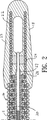
図1に示している実施形態においては、EP装置10は誘導線の形態をなしている。図1に示しているEP装置の拡大縦断面を示している図2で最もよく分かるように、芯部材20は、軸11の中をこの装置の末端部まで延在している。柔らかい柔軟性のあるチップ18は、閉じた末端部を有しており、そして好ましくは高分子材料から形成されている柔らかい包被(被膜)23で包まれ軸11の末端部を越えて延在している柔軟なコイル22を含んでいる。図2に示している実施形態においては、チップ18は、柔軟性を高めるために開いた中央領域を持っている。チップ18にとって好適な高分子材料は、3Mが販売しているTHVなどのフルオロポリマーである。芯部材20は、金−錫はんだ(Au80%−Sn20%)などの適切な材料によってコイル22の遠位端に24で固定されている。芯部材20、そして好適にはその末端部は、図示しているようにテーパを付けたり、平坦にしたりできる。
【0020】
カテーテル形態の装置(図示していない)は、図1に示している誘導線形態(ガイドワイヤ形態)と同じであるが、芯部材20がなく、軸11内に内腔が延在していて、誘導線(ガイドワイヤ)あるいはその他の装置をその中に受け入れるようになっているところが異なる。
【0021】
芯部材20は、最大直径が約0.01インチ(0.25mm)ないし約0.018インチ(0.46mm)のステンレス鋼線(ステンレス・スチール・ワイヤ)が好ましい。この芯部材20には、全体厚さが、好適には0.001インチ(0.025mm)以下の1つまたはそれ以上の包被(ジャケット)が設けられる。本発明の好適な実施形態においては、この芯部材の包被は、約0.001インチ(0.025mm)の厚さの絶縁ポリイミド被膜(コーティング)27を有していて、これは末端のテーパ部では、約0.004インチ(0.102mm)ないし約0.005インチ(0.127mm)厚さのTHVなどのフルオロポリマー被膜(コーティング)28で覆われている。図2に示している実施形態においては、被膜27は、軸11の末端に対して更に末端方向の所定のポイントまで延在すると共に、芯部材20の末端に対して基部方向の所定のポイントまで延在している。
【0022】
図1−5に示している実施形態においては、電極16は螺旋コイルであって、絶縁されている導電体29に電気的に接続されている。温度センサ17は熱電対線(ワイヤ)30および31によって形成されている熱電対である。図3の4−4線および5−5線横断面図である図4および5に最もよく示されているように、編組みされた導電体29は36AWG銅線でできており、それぞれの導電体は約0.0005インチ(0.013mm)のポリイミド絶縁被膜を有している。熱電対線は、41AWG銅とコンスタンタンからできていて、それぞれの線(ワイヤ)には約0.00025インチ(0.007mm)ないし約0.0005インチ(0.013mm)厚さのポリイミド絶縁塗装を有している。
【0023】
軸11は、導電体29と熱電対線(ワイヤ)とを有していて、少なくとも部分的に包被(ジャケット)32で覆われている編組構造を有している。本発明の好適な実施形態においては、包被32はTHVなどのフルオロポリマーである。図1に示している本発明の好適な実施形態においては、編組導電体29と熱電対線30、31も、また、芯部材20の周りの被膜28内に少なくとも部分的に位置している。
【0024】
伝導体(伝導部材)33が温度センサ17の外面を覆っている。伝導体33は、好ましくは、約0.001インチ(0.025mm)ないし約0.005インチ(0.13mm)の厚さの金製の帯(バンド)であり、そして、好ましくは、軸11の周りに配置され、約0.002インチ(0.05mm)の厚さを有し、金−錫はんだなどの適切な材料で温度センサ17に接続される。図1に示している本発明の好適な実施形態においては、好ましくはTHVでできているフルオロポリマーの包被34が伝導体33を覆い、電極へ送られるエネルギーによる雑音(RF雑音など)から温度センサ17を隔離(insulates)している。包被(ジャケット)34は、電極16の少なくとも部分、例えば、それぞれの電極の縁を覆い、電極の鋭利な金属の縁が露出しないようにしてある。別の実施形態(図示していない)においては、包被34は、例えば、信号雑音を除くフィルタ機能を備えている場合は省略できる。包被34を省略すると創傷部位に更に直接接触できるので、更に迅速に、正確に温度計測ができるようになる。同様に、電極エネルギーからの雑音を別の方法で除去すれば、熱電対を直接電極コイルに取り付けることができ、より迅速に且つ正確な応答が得られる。
【0025】
図1に示している本発明の好適な実施形態においては、熱電対線の末端部が互いに結合され、これにより形成された熱電対が、それら2つの線(ワイヤ)のインターフェースにおける温度を測定するようになっている。選択的に、熱電対線の末端部を、別々に離間させた配置で、伝導体33に固定することができ、これにより、熱電対は、熱電対線の末端部の間の伝導体33の長さに沿いの温度を測定することになる。
【0026】
電極の最大外形寸法は、一般に、約1.0mm(3Fr)ないし約1.3mm(4Fr)で、好適には約1.22mm(3.7Fr)である。電極の長さは約2mmないし約8mmで、好適には約6mmである。電極間の間隔は、温度センサを収容できるに十分な大きさでなければならないが、一般に、約1mmないし約3mm、好適には約2mmである。本発明の好適な実施形態においては、約4個ないし約12個の個々の電極が末端軸部に設けられるが、該末端軸部の直径が5Fr以上になった場合、装置は、更に多数の電極を設けることができる。
【0027】
EP装置10は、コネクタ14を含めて、全長が約100cmないし約200cm、好ましくは約165cmである。電極16を有する末端軸部(distal shaft section)13の長さは、約2cmないし約15cm、好ましくは約6cmである。
【0028】
EP装置10は、患者の大腿静脈などの血管系に経皮的にあるいは静脈切開で誘導部材の中に入れて導入する。通常、この装置は患者の心房内で線形離解(linear ablation)を行うのに使用するが、心室(ventricle)の中に創傷を作るのにも使用することができる。装置は、通常、大静脈の内部に進められてゆき、末端軸部13が適正な心房内に配置される。選択的に、この装置は、中隔横断静脈鞘を通って左心房へ前進せしめられたり、あるいは大腿動脈進入部を経て大動脈および左心室へ逆行せしめられたりすることができる。処置の間、患者から延在している装置10の基軸部12を捻ることによって、末端部13が心房腔(atrial chamber)内で回転して変位し、EP装置10を適切な位置に持っていくことができ、以て、電気的活動(electrical activity)が検出でき、腔(チャンバ)内の多くの部位で心臓組織を切除(除去)することが可能になる。本質的に、電気的な活動を感知するとき、総ての電極16を同時に使用するが、離解(ablation)を行うとき、典型的な処置(施術)としては、EP装置の最末端部における1個または2個の電極にRF電流を流して最初の離解を行い、次いで、基部方向に1個または2個の電極に続けていって、所望の長さの離解(剥離、分離、切除、切断、ablation)を心房腔の中で行うのである。これによって、組立に必要な全体的なパワー要求(必要条件)が減少する。温度センサは、隣り合う電極の間にある心臓壁の温度を検出するので、各電極に供給する電力は、所望の方法で温度を制御する適切な装置(図示していない)で制御されることができ、そしていつ連続的な創傷(lesion)が形成され、従って、いつ基部方向に向けて次の電極に移動するべきかが判断される。しかし、複数チャネルの温度感知装置と十分なパワー源を使えば、特定の数の電極、あるいは総ての電極にRFエネルギーを同時に供給することも可能である。
【0029】
好適な使用においては、温度データをフィードバックすることによって電力(パワー)を調整し、血栓を防止することができる。同時係属出願番号第08/629,057号の出願に記載されている如く、選択的に、冷却液を使用することもできる。
【0030】
離解(ablation)が終了すると、電極16を使って電気的活動を検出し、その離解が細動あるいは粗動を終わらせるのに有効であったことを確かめることができる。通常、本発明の装置で形成される細長い創傷は、幅が約3mmないし約12mmであり、通常は、約5mmないし10mmである。
【0031】
この装置の基端部にある電気コネクタ14は市販の電気コネクタであって、8ピン・コネクタ用には部品番号PAB−M08−GLA39JあるいはPAB−M08−TLA39Jがあり、9−16ピンなどもっとピン数の多いコネクタ用には部品番号PAB−M08−GLA39Aなどがある。上記のコネクタは、カリフォルニア州サンタ・ローザのレモ・ユーエスエー社から入手できる。上記のコネクタに接続可能なアクセサリ・ケーブル用の適切なコネクタには、8ピン・コネクタ用にはPRB−M08−GLL65J、8ピン以上のコネクタ用にはPRB−M08−GII65Aがある。後者のコネクタも、同社から入手可能である。
【0032】
ここでは、心房性細動および粗動の検出と治療を指向している特定の好適な実施形態に関して記載してきたが、当業者であれば、細長い創傷(lesion)を形成するという広範囲の処置に本発明が使用できるということを認識するであろう。更に、本発明の実施形態のそれぞれの特徴は、幾つかの図面に示される一方、他の図面には示されなかったが、当業者であれば、本発明の1つの実施形態のそれぞれの特徴は、他の実施形態のいずれかの、あるいは総ての特徴と結合させることができるということを認識するであろう。本発明について、その範囲から逸脱することなく、様々な修正(モディフィケーション)および改良をすることが可能である。
【図面の簡単な説明】
【図1】本発明の特徴を具体化しているEP装置の正面図である。
【図2】図1に示しているEP装置の2−2線拡大縦断面図である。
【図3】図1に示しているEP装置の3−3線拡大部分縦断面図である。
【図4】図3に示しているEP装置の4−4線横断面図である。
【図5】図3に示しているEP装置の5−5線横断面図である。[0001]
(Technical field)
The present invention relates generally to the detection and removal of cardiac arrhythmias, and more particularly to the detection and removal of atrial fibrillation and atrial flutter.
[0002]
(Background technology)
Atrial fibrillation is a disorder of the patient's atrial depolarization with little or no atrial contraction. The condition is chronic or intermittent and currently about 2 million people are affected in the United States alone. Previous methods of treating arrhythmias in patients include the use of antiarrhythmic drugs such as sodium and calcium channel blockers and drugs that reduce beta adrenergic activity. Other methods include sources of signals that cause arrhythmias and surgically disconnecting such signal paths. However, this surgical procedure (technique) is traumatic and unacceptable for many patients. More frequently used treatments to end arrhythmias include applying heat to the desired arrhythmogenic site on the patient's endocardium, such as irradiating a laser beam or high-frequency electrical energy such as RF or microwave. Including those that destroy heart tissue, causing arrhythmias. In the latter method, an intravascular electrophysiological (EP) device can be used to create adjacent lesions in the patient's atrium so that it can be atrial as well as surgical isolation. It helps to end fibrillation and make trauma much smaller.
[0003]
Typically, the EP device travels through the patient's vasculature to reach the heart and emits RF electrical energy from the device's electrodes to form a wound in the endocardium. A wound is made in a fairly small area by RF dissection. Therefore, it is common to make several wounds and completely remove areas larger than the average arrhythmogenic site. A major problem with RF dissection is to create a wound of the required size, completely resecting the area of interest and not destroying surrounding healthy tissue more than necessary.
[0004]
There was a need for an ablation device that could improve the monitoring of wound formation and create a linear wound of the required length. The present invention satisfies these and other needs.
[0005]
(Disclosure of the Invention)
The present invention relates to an electrophysiological (EP) device having a small outline suitable for forming a linear dissection site (ablation site, cutting site, incision site, ablations) in a chamber (chamber) of a patient's heart. Is directed to. The EP device of the present invention has electrodes and a temperature sensor along the outer surface of the device. Its configuration reduces profile, improves wound formation monitoring, and improves wound size control. Such linear disintegration wounds are particularly suitable for eliminating or minimizing atrial fibrillation and flutter by isolating (separating) the patient's atrial wall sections. .
[0006]
The EP device of the present invention generally has a proximal portion (base portion), a distal portion (end portion), and a plurality of at least partially exposed electrodes provided on the outer surface of the distal portion. It has an elongated shaft. These electrodes are spaced apart in the longitudinal direction of the distal portion, and at least one temperature sensor is located between adjacent electrodes.
[0007]
These distal shaft electrodes form a wound in the chamber of the patient's heart when electrical energy, preferably RF energy, is emitted therefrom. These electrodes can be a combination of a sensing electrode and a disaggregating electrode that disaggregates and detects electrical activity from inside the lumen of the patient's body. Can do. In a preferred embodiment, the electrode on the axis of the device is independent when the electrode that contacts the outside of the patient's body is in monopolar mode. Optionally, using a pair of electrodes on the axis, the electrodes can also be bipolar. The preferred electrode has the shape of a helical coil to improve the flexibility of the device, but other configurations such as a cylindrical band, arcuate band or ribbon (ribbon) are also suitable. To increase sensing resolution, the electrodes are spaced apart by a first small array of electrodes attached to the distal shaft and are a second enlarged array of sensing electrodes attached to the distal shaft. The electrodes are spaced apart by a second enlarged array where the spacing between the electrodes is larger than the first small array. This is described in a co-pending application entitled “High Resolution Intravascular Signal Detection” filed on May 18, 1995, application number 08 / 443,657, which is hereby incorporated by reference in its entirety. Be incorporated.
[0008]
The preferred temperature sensor is a thermocouple, but other suitable temperature sensors such as a thermistor or other temperature sensing means may be used. A suitable thermocouple is a T type made of copper and a constantan wire (wire). The conductive member can be provided on the outer surface of the temperature sensor. The conducting member is formed of a conducting material, such as gold, that quickly balances the temperature of the outer circumference of the catheter to the temperature of the patient's heart wall.
[0009]
By placing the temperature sensor between the electrodes on the outer surface of the device, a low profile device can be provided. By reducing the contour, it is easier to maneuver and position the working distal end of the device in the patient's body. The maximum outer diameter of the distal shaft of this device is about 1.0 mm (3.0 French) to about 1.3 mm (4 French). In contrast to the EP device of the present invention, the EP device in which the temperature sensors are arranged radially (in the radial direction) at a position between the electrodes and the central axis of the device and spaced apart from the axis is more effective than the EP device of the present invention A large diameter shaft is required.
[0010]
Furthermore, the EP device of the present invention improves temperature monitoring during wound formation, allowing more effective wound formation. To effectively remove an arrhythmogenic site, individual wounds formed by adjacent electrodes must be brought together so that the area of interest is completely excised to form one continuous wound. I must. However, if wound formation is incomplete, the wound will not be continuous and the arrhythmia will not stop. The temperature sensor located on the distal side or the base side with respect to the shaft portion where the electrode is disposed, or the temperature sensor spaced radially (radially) from the electrode provided in the shaft of the device, The temperature of the heart wall between adjacent electrodes cannot be accurately measured, and therefore disintegration (resection) cannot be effectively monitored to reliably form a continuous wound. In contrast, the EP device of the present invention monitors the temperature of the heart wall at the edges of adjacent wounds that meet or overlap to form one continuous wound. By monitoring the temperature in this manner, the surgeon can be confident that sufficient heating is taking place and avoid overheating that causes blood clotting and tissue charring. Thus, the surgeon applies dissociation (ablation) energy to adjacent electrodes so that the heart wall between the electrodes reaches a predetermined temperature within a predetermined time. In this way, the surgeon can monitor wound formation and determine when one continuous wound of the desired size has been formed.
[0011]
The distal wall is formed from at least portions of individually insulated conductors that are electrically connected to respective electrodes of the distal section. The conductor is preferably braided. The individual conducting wires (conducting wires) on the distal wall are also connected to a temperature sensor or, in the case of a thermocouple temperature sensor, the conducting wires are connected to the end (distal end) forming the temperature sensor. ). Further, a plurality of polymer strands made of nylon such as Dacron (DuPont) may be knitted together with the conductor, or separately knitted outside the tubular member formed by the braided conductor. The proximal end of the conductor is electrically connected to a respective pin of a multi-pin connector provided at the proximal end of the shaft, and high frequency electrical energy is transferred from its source to the individual electrodes (external electrodes). Or to the electrode pair. A multi-pin connector provided at the proximal end of the shaft is also configured to be connected to a receiving member in electrical communication with a display unit capable of displaying sensed electrical activity.
[0012]
In a preferred embodiment of the present invention, the EP device of the present invention is in the form of a guide wire having an elongated core member provided inside the device shaft. The distal portion of the guide wire has a flexible guide tip (guide tip) located distal (terminal) with respect to the length direction to which the electrode is attached. This distal guide tip is around an independent forming member, such as a helical coil provided around the most distal end of the core member or a ribbon extending from the most distal end of the core member Can have a spiral coil. The distal end of this core member or independent shape member can be manually deformed by the surgeon so that the patient's pulse can be obtained by twisting the proximal end extending from the patient during the procedure. The elongate sensing device is easily operated within the tube structure. A smooth round tip or plug is provided at the distal end of the coil, which prevents the vessel from being damaged as it travels through the patient's vasculature. A conventional guide wire structure can be used. An electrode is provided at the distal end of the EP device, and the core member is used to deliver current to the electrode at the distal end.
[0013]
The core member is preferably covered with one or more jackets that can be electrically insulated. With this design, the contour can be reduced and flexibility can be provided. In addition, this configuration is strong enough to ensure effective contact between the length of the electrode and the area of the patient's endocardium where disaggregation takes place, and to form an effective wound that terminates the arrhythmia. To do. The individually insulated conductors may be located at least partially inside the jacket (outer jacket) of the core member.
[0014]
The elongated device of the present invention comprises a catheter having an elongated lumen extending from a proximal end (proximal end) to a release port or guide wire port (guidewire port) located at the distal end (terminal end) of the device. It may be in the form of A soft tip can be provided at the distal end of the catheter to minimize the risk of getting caught and damaged by the blood vessel as it travels through the blood vessel. In one preferred embodiment, the lumen of the device in the form of a catheter is a conventional guide wire or guide wire of the device of the present invention that allows detection of signals at different locations within the same blood vessel or within its branch. Configured to pass through. This is described in a co-pending application entitled “Method and System Using Multiple Vascular Sensing Devices for Detecting Electrical Activity” in application Ser. No. 08 / 188,298, filed Jan. 27, 1994. This application is incorporated herein in its entirety.
[0015]
The EP device of the present invention can be used alone or together with a guide member (guide member) of various shapes or deformable into various shapes. In one preferred embodiment, the EP device is deflectable having a lumen that slidably receives the EP device and a distal portion that can be deflected in either of two directions relative to the longitudinal axis of the guide catheter. Used with various guide catheters. This is referred to as “deflectable guide catheter” of application number 09 / 001,249, whose inventors filed on December 30, 1997 are Jay J. Quinn, Duane Dickens, and Laurent Schaller. Which is described in the co-pending application of the name, which is incorporated herein in its entirety.
[0016]
The EP device of the present invention can also be used with a guide member having an elongated open distal portion. This is a co-pending application entitled “Linear Ablation Assembly”, filed 08/08 / 629,057, filed Aug. 8, 1996, and 08 / 659,769, filed Jun. 6, 1996. This application is incorporated herein in its entirety. Due to the longitudinal movement of the EP device located in the lumen of the delivery sheath, the distal portion of the EP device protrudes in an arc away from the open distal portion of the delivery sheath, and the patient's heart Effective contact with the surface of the chamber, thereby effectively defibrillating (cutting) the heart tissue.
[0017]
The EP catheter of the present invention has a small profile because the temperature sensor is located along the outer surface of the axis of the device and between the electrodes, thereby improving operability. . Also, the location of the temperature sensor can effectively monitor wound formation, which improves the control of wound size. As a result, the area in question can be completely excised without undesired destruction of the surrounding tissue. These and other advantages of the present invention will become more apparent from the following detailed description and the accompanying exemplary drawings.
(Best Mode for Carrying Out the Invention)
[0018]
As shown in FIG. 1, the EP device (electrophysiological catheter) 10 of the present invention generally has a base shaft portion (proximal shaft portion) 12 and a terminal shaft portion (distal shaft portion) 13. An elongated shaft 11, an electrical connector 14 on the proximal side of the device, a plurality of
[0019]
In the embodiment shown in FIG. 1, the EP device 10 is in the form of a guide wire. As best seen in FIG. 2, which shows an enlarged longitudinal section of the EP device shown in FIG. 1, the
[0020]
A catheter type device (not shown) is the same as the guide wire type (guide wire type) shown in FIG. 1 except that there is no
[0021]
The
[0022]
In the embodiment shown in FIGS. 1-5, the
[0023]
The shaft 11 has a
[0024]
A conductor (conductive member) 33 covers the outer surface of the temperature sensor 17. The
[0025]
In the preferred embodiment of the present invention shown in FIG. 1, the ends of the thermocouple wires are bonded together so that the thermocouple formed thereby measures the temperature at the interface of the two wires (wires). It is like that. Optionally, the end of the thermocouple wire can be secured to the
[0026]
The maximum outer dimension of the electrode is generally from about 1.0 mm (3 Fr) to about 1.3 mm (4 Fr), preferably about 1.22 mm (3.7 Fr). The length of the electrode is about 2 mm to about 8 mm, preferably about 6 mm. The spacing between the electrodes must be large enough to accommodate the temperature sensor, but is generally about 1 mm to about 3 mm, preferably about 2 mm. In a preferred embodiment of the present invention, about 4 to about 12 individual electrodes are provided on the distal shaft, but if the diameter of the distal shaft is greater than 5 Fr, the device is more An electrode can be provided.
[0027]
The EP device 10 including the connector 14 has an overall length of about 100 cm to about 200 cm, preferably about 165 cm. The length of the distal shaft section 13 with the
[0028]
The EP device 10 is introduced into a blood vessel system such as a femoral vein of a patient by being percutaneously or inserted into a guide member by phlebotomy. Typically, this device is used to perform linear ablation within the patient's atrium, but can also be used to create a wound in the ventricle. The device is usually advanced into the vena cava and the distal stem 13 is placed in the proper atrium. Optionally, the device can be advanced through the transseptal venous sheath into the left atrium, or can be retrograde into the aorta and left ventricle via the femoral artery entry. During the procedure, twisting the proximal portion 12 of the device 10 extending from the patient causes the distal portion 13 to rotate and displace within the atrial chamber, holding the EP device 10 in place. So that electrical activity can be detected and the heart tissue can be excised (removed) at many sites within the chamber. In essence, all
[0029]
In a preferred use, power can be adjusted by feeding back temperature data to prevent thrombus. Optionally, a coolant may be used as described in the co-pending application Ser. No. 08 / 629,057.
[0030]
When the ablation is complete, the
[0031]
The electrical connector 14 at the base end of this device is a commercially available electrical connector, and for 8-pin connectors there are part numbers PAB-M08-GLA39J or PAB-M08-TLA39J, more pins such as 9-16 pins For connectors with a large number, there are part numbers PAB-M08-GLA39A and the like. Such connectors are available from Remo USA, Inc., Santa Rosa, California. Suitable connectors for accessory cables that can be connected to the above connectors include PRB-M08-GLL65J for 8-pin connectors and PRB-M08-GII65A for 8-pin and higher connectors. The latter connector is also available from the company.
[0032]
Although described herein with respect to certain preferred embodiments directed to the detection and treatment of atrial fibrillation and flutter, those skilled in the art will be familiar with a wide range of procedures to form elongated lesions. It will be appreciated that the present invention can be used. Further, while each feature of an embodiment of the present invention is shown in some drawings and not shown in other drawings, those skilled in the art will appreciate each feature of one embodiment of the present invention. Will recognize that any or all of the other embodiments may be combined. Various modifications and improvements can be made to the present invention without departing from the scope thereof.
[Brief description of the drawings]
FIG. 1 is a front view of an EP device embodying features of the present invention.
FIG. 2 is an enlarged longitudinal sectional view taken along line 2-2 of the EP device shown in FIG.
FIG. 3 is an enlarged partial vertical sectional view taken along line 3-3 of the EP device shown in FIG. 1;
4 is a cross-sectional view taken along line 4-4 of the EP device shown in FIG. 3;
5 is a cross-sectional view taken along line 5-5 of the EP device shown in FIG.
Claims (28)
b)末端軸部上に設けられた複数の電極と、
c)末端軸部上に設けられた複数の温度センサであって、電極の間に位置する組織の温度を検知するべく個々の温度センサが2つの隣り合う電極間に配置されている温度センサと、
d)各温度センサに接した状態で該各温度センサに設けられた伝導性の金属バンドと、
を有する、患者の組織に創傷を形成するための電気生理学的装置。a) an elongated shaft having a proximal end, a distal end, and a distal shaft;
b) a plurality of electrodes provided on the terminal shaft,
c) a plurality of temperature sensors provided on the distal shaft, each temperature sensor being arranged between two adjacent electrodes to detect the temperature of the tissue located between the electrodes ; ,
d) a conductive metal band provided on each temperature sensor in contact with each temperature sensor;
An electrophysiological device for forming a wound in a patient's tissue .
Applications Claiming Priority (3)
| Application Number | Priority Date | Filing Date | Title |
|---|---|---|---|
| US09/104,752 US6251107B1 (en) | 1998-06-25 | 1998-06-25 | Ep catheter |
| US09/104,752 | 1998-06-25 | ||
| PCT/US1999/014272 WO1999066851A1 (en) | 1998-06-25 | 1999-06-25 | Ep catheter |
Publications (3)
| Publication Number | Publication Date |
|---|---|
| JP2002539850A JP2002539850A (en) | 2002-11-26 |
| JP2002539850A5 JP2002539850A5 (en) | 2007-05-31 |
| JP4125489B2 true JP4125489B2 (en) | 2008-07-30 |
Family
ID=22302181
Family Applications (1)
| Application Number | Title | Priority Date | Filing Date |
|---|---|---|---|
| JP2000555541A Expired - Fee Related JP4125489B2 (en) | 1998-06-25 | 1999-06-25 | Electrophysiology catheter |
Country Status (5)
| Country | Link |
|---|---|
| US (1) | US6251107B1 (en) |
| EP (1) | EP1089667A4 (en) |
| JP (1) | JP4125489B2 (en) |
| AU (1) | AU4830099A (en) |
| WO (1) | WO1999066851A1 (en) |
Families Citing this family (68)
| Publication number | Priority date | Publication date | Assignee | Title |
|---|---|---|---|---|
| US20010025192A1 (en) * | 1999-04-29 | 2001-09-27 | Medtronic, Inc. | Single and multi-polar implantable lead for sacral nerve electrical stimulation |
| EP1180004A1 (en) * | 1999-05-18 | 2002-02-20 | Silhouette Medical Inc. | Surgical weight control device |
| US6746446B1 (en) * | 2000-08-04 | 2004-06-08 | Cardima, Inc. | Electrophysiological device for the isthmus |
| US6972016B2 (en) * | 2001-05-01 | 2005-12-06 | Cardima, Inc. | Helically shaped electrophysiology catheter |
| AUPS226502A0 (en) * | 2002-05-13 | 2002-06-13 | Advanced Metal Coatings Pty Limited | A multi-electrode lead |
| US20040082859A1 (en) | 2002-07-01 | 2004-04-29 | Alan Schaer | Method and apparatus employing ultrasound energy to treat body sphincters |
| US20050033137A1 (en) * | 2002-10-25 | 2005-02-10 | The Regents Of The University Of Michigan | Ablation catheters and methods for their use |
| US20040082947A1 (en) | 2002-10-25 | 2004-04-29 | The Regents Of The University Of Michigan | Ablation catheters |
| EP1585434B1 (en) * | 2002-11-18 | 2015-01-14 | Mediguide Ltd. | System for mounting an mps sensor on a catheter |
| US7881769B2 (en) | 2002-11-18 | 2011-02-01 | Mediguide Ltd. | Method and system for mounting an MPS sensor on a catheter |
| US8862204B2 (en) | 2002-11-18 | 2014-10-14 | Mediguide Ltd. | Reducing mechanical stress on conductors and connection points in a position determinable interventional medical device |
| US20060089637A1 (en) | 2004-10-14 | 2006-04-27 | Werneth Randell L | Ablation catheter |
| US8617152B2 (en) | 2004-11-15 | 2013-12-31 | Medtronic Ablation Frontiers Llc | Ablation system with feedback |
| US7468062B2 (en) | 2004-11-24 | 2008-12-23 | Ablation Frontiers, Inc. | Atrial ablation catheter adapted for treatment of septal wall arrhythmogenic foci and method of use |
| US7429261B2 (en) | 2004-11-24 | 2008-09-30 | Ablation Frontiers, Inc. | Atrial ablation catheter and method of use |
| CA2612679A1 (en) | 2005-06-20 | 2007-01-04 | Richardo D. Roman | Ablation catheter |
| US8834461B2 (en) | 2005-07-11 | 2014-09-16 | Medtronic Ablation Frontiers Llc | Low power tissue ablation system |
| US8657814B2 (en) * | 2005-08-22 | 2014-02-25 | Medtronic Ablation Frontiers Llc | User interface for tissue ablation system |
| US7316507B2 (en) | 2005-11-03 | 2008-01-08 | Covidien Ag | Electronic thermometer with flex circuit location |
| US8641704B2 (en) | 2007-05-11 | 2014-02-04 | Medtronic Ablation Frontiers Llc | Ablation therapy system and method for treating continuous atrial fibrillation |
| US8496377B2 (en) * | 2007-12-31 | 2013-07-30 | Covidien Lp | Thermometer having molded probe component |
| US8974445B2 (en) | 2009-01-09 | 2015-03-10 | Recor Medical, Inc. | Methods and apparatus for treatment of cardiac valve insufficiency |
| JP6045916B2 (en) * | 2010-02-26 | 2016-12-14 | コーニンクレッカ フィリップス エヌ ヴェKoninklijke Philips N.V. | Interventional ablation device with tissue identification capability |
| US9314616B2 (en) * | 2010-04-14 | 2016-04-19 | Medtronic, Inc. | Temporary implantable medical electrical leads |
| US20140024962A1 (en) * | 2010-12-29 | 2014-01-23 | Lisa A. Dunn | Temperature Measuring Device |
| WO2012100355A1 (en) | 2011-01-30 | 2012-08-02 | University Health Network | Coil electrode for thermal therapy |
| CN104066368B (en) | 2011-09-22 | 2017-02-22 | 乔治华盛顿大学 | Systems and methods for visualizing ablated tissue |
| EP2757933B1 (en) | 2011-09-22 | 2019-02-06 | The George Washington University | Systems for visualizing ablated tissue |
| JP6301926B2 (en) | 2012-08-09 | 2018-03-28 | ユニバーシティ オブ アイオワ リサーチ ファウンデーション | Catheter, catheter system, and method for piercing tissue structure |
| US20140257130A1 (en) * | 2013-03-11 | 2014-09-11 | Boston Scientific Scimed, Inc. | Powered pull wire design for ablation catheters |
| US20150141847A1 (en) | 2013-11-20 | 2015-05-21 | The George Washington University | Systems and methods for hyperspectral analysis of cardiac tissue |
| WO2015103574A1 (en) | 2014-01-06 | 2015-07-09 | Iowa Approach Inc. | Apparatus and methods for renal denervation ablation |
| EP3139997B1 (en) | 2014-05-07 | 2018-09-19 | Farapulse, Inc. | Apparatus for selective tissue ablation |
| WO2015192027A1 (en) | 2014-06-12 | 2015-12-17 | Iowa Approach Inc. | Method and apparatus for rapid and selective transurethral tissue ablation |
| WO2015192018A1 (en) | 2014-06-12 | 2015-12-17 | Iowa Approach Inc. | Method and apparatus for rapid and selective tissue ablation with cooling |
| WO2016060983A1 (en) | 2014-10-14 | 2016-04-21 | Iowa Approach Inc. | Method and apparatus for rapid and safe pulmonary vein cardiac ablation |
| CN107427213B (en) | 2014-11-03 | 2021-04-16 | 460医学股份有限公司 | System and method for evaluation of contact quality |
| WO2016073476A1 (en) | 2014-11-03 | 2016-05-12 | The George Washington University | Systems and methods for lesion assessment |
| WO2016081606A1 (en) | 2014-11-19 | 2016-05-26 | Advanced Cardiac Therapeutics, Inc. | Systems and methods for high-resolution mapping of tissue |
| WO2016081611A1 (en) | 2014-11-19 | 2016-05-26 | Advanced Cardiac Therapeutics, Inc. | High-resolution mapping of tissue with pacing |
| CA2967824A1 (en) | 2014-11-19 | 2016-05-26 | Advanced Cardiac Therapeutics, Inc. | Ablation devices, systems and methods of using a high-resolution electrode assembly |
| US20160184588A1 (en) * | 2014-12-30 | 2016-06-30 | Catheter Robotics, Inc. | Combined Esophageal Temperature Monitor and Pacing Device |
| US9636164B2 (en) | 2015-03-25 | 2017-05-02 | Advanced Cardiac Therapeutics, Inc. | Contact sensing systems and methods |
| US10779904B2 (en) | 2015-07-19 | 2020-09-22 | 460Medical, Inc. | Systems and methods for lesion formation and assessment |
| US10172673B2 (en) | 2016-01-05 | 2019-01-08 | Farapulse, Inc. | Systems devices, and methods for delivery of pulsed electric field ablative energy to endocardial tissue |
| US10130423B1 (en) | 2017-07-06 | 2018-11-20 | Farapulse, Inc. | Systems, devices, and methods for focal ablation |
| US10660702B2 (en) | 2016-01-05 | 2020-05-26 | Farapulse, Inc. | Systems, devices, and methods for focal ablation |
| US20170189097A1 (en) | 2016-01-05 | 2017-07-06 | Iowa Approach Inc. | Systems, apparatuses and methods for delivery of ablative energy to tissue |
| JP6923549B2 (en) | 2016-03-15 | 2021-08-18 | エピックス セラピューティクス,インコーポレイテッド | Improved system for irrigation cauterization |
| EP3471631A4 (en) | 2016-06-16 | 2020-03-04 | Farapulse, Inc. | Systems, apparatuses, and methods for guide wire delivery |
| KR101963621B1 (en) * | 2016-11-04 | 2019-04-01 | 주식회사 스타메드 | Radiofrequency ablation device |
| WO2018129455A1 (en) | 2017-01-09 | 2018-07-12 | Boston Scientific Scimed, Inc. | Guidewire with tactile feel |
| US9987081B1 (en) | 2017-04-27 | 2018-06-05 | Iowa Approach, Inc. | Systems, devices, and methods for signal generation |
| EP3614946B1 (en) | 2017-04-27 | 2024-03-20 | EPiX Therapeutics, Inc. | Determining nature of contact between catheter tip and tissue |
| US10617867B2 (en) | 2017-04-28 | 2020-04-14 | Farapulse, Inc. | Systems, devices, and methods for delivery of pulsed electric field ablative energy to esophageal tissue |
| JP2020533050A (en) | 2017-09-12 | 2020-11-19 | ファラパルス,インコーポレイテッド | Systems, devices, and methods for ventricular focal ablation |
| CN112087978B (en) | 2018-05-07 | 2023-01-17 | 波士顿科学医学有限公司 | Epicardial ablation catheter |
| EP3790483A1 (en) | 2018-05-07 | 2021-03-17 | Farapulse, Inc. | Systems, apparatuses, and methods for filtering high voltage noise induced by pulsed electric field ablation |
| WO2019217433A1 (en) | 2018-05-07 | 2019-11-14 | Farapulse, Inc. | Systems, apparatuses and methods for delivery of ablative energy to tissue |
| EP3851060B1 (en) * | 2018-09-14 | 2023-08-09 | Hangzhou Broncus Medical Co., Ltd. | Radio frequency ablation catheter, radio frequency ablation system for lungs |
| WO2020061359A1 (en) | 2018-09-20 | 2020-03-26 | Farapulse, Inc. | Systems, apparatuses, and methods for delivery of pulsed electric field ablative energy to endocardial tissue |
| JP2020081217A (en) * | 2018-11-21 | 2020-06-04 | 国立大学法人 新潟大学 | Ablation catheter and cardiac therapy system |
| US10625080B1 (en) | 2019-09-17 | 2020-04-21 | Farapulse, Inc. | Systems, apparatuses, and methods for detecting ectopic electrocardiogram signals during pulsed electric field ablation |
| US11065047B2 (en) | 2019-11-20 | 2021-07-20 | Farapulse, Inc. | Systems, apparatuses, and methods for protecting electronic components from high power noise induced by high voltage pulses |
| US11497541B2 (en) | 2019-11-20 | 2022-11-15 | Boston Scientific Scimed, Inc. | Systems, apparatuses, and methods for protecting electronic components from high power noise induced by high voltage pulses |
| US10842572B1 (en) | 2019-11-25 | 2020-11-24 | Farapulse, Inc. | Methods, systems, and apparatuses for tracking ablation devices and generating lesion lines |
| KR20220037903A (en) * | 2020-09-18 | 2022-03-25 | (주) 타우피엔유메디칼 | RF ablation catheter for atrial fibrillation, and method for artial fibrillation in use of it |
| CN115341889B (en) * | 2022-05-20 | 2023-03-24 | 中国石油天然气集团有限公司 | Underground discharging operation system with externally-coated bearing cable electrode |
Family Cites Families (11)
| Publication number | Priority date | Publication date | Assignee | Title |
|---|---|---|---|---|
| US4966597A (en) | 1988-11-04 | 1990-10-30 | Cosman Eric R | Thermometric cardiac tissue ablation electrode with ultra-sensitive temperature detection |
| JP2866132B2 (en) * | 1990-01-29 | 1999-03-08 | テルモ株式会社 | Flow sensor probe |
| US5682899A (en) * | 1991-05-16 | 1997-11-04 | Ami-Med Corporation | Apparatus and method for continuous cardiac output monitoring |
| WO1994002077A2 (en) | 1992-07-15 | 1994-02-03 | Angelase, Inc. | Ablation catheter system |
| US5706809A (en) * | 1993-01-29 | 1998-01-13 | Cardima, Inc. | Method and system for using multiple intravascular sensing devices to detect electrical activity |
| DE69433383T2 (en) * | 1993-10-01 | 2004-10-07 | Target Therapeutics Inc | MULTIPOLE CATHETER AND MULTIPOLAR GUIDE WIRE FOR MEASURING THE ELECTRICAL HEART ACTIVITY |
| US5582609A (en) | 1993-10-14 | 1996-12-10 | Ep Technologies, Inc. | Systems and methods for forming large lesions in body tissue using curvilinear electrode elements |
| US6129724A (en) * | 1993-10-14 | 2000-10-10 | Ep Technologies, Inc. | Systems and methods for forming elongated lesion patterns in body tissue using straight or curvilinear electrode elements |
| US5531781A (en) * | 1993-11-02 | 1996-07-02 | Alferness; Clifton A. | Implantable lead having a steering distal guide tip |
| ES2214493T3 (en) * | 1994-06-27 | 2004-09-16 | Boston Scientific Limited | A TISSUE ABLATION REGULATION SYSTEM USING THE TEMPERATURE SENSORS. |
| US5885278A (en) * | 1994-10-07 | 1999-03-23 | E.P. Technologies, Inc. | Structures for deploying movable electrode elements |
-
1998
- 1998-06-25 US US09/104,752 patent/US6251107B1/en not_active Expired - Lifetime
-
1999
- 1999-06-25 WO PCT/US1999/014272 patent/WO1999066851A1/en active Application Filing
- 1999-06-25 JP JP2000555541A patent/JP4125489B2/en not_active Expired - Fee Related
- 1999-06-25 EP EP99931883A patent/EP1089667A4/en not_active Withdrawn
- 1999-06-25 AU AU48300/99A patent/AU4830099A/en not_active Abandoned
Also Published As
| Publication number | Publication date |
|---|---|
| JP2002539850A (en) | 2002-11-26 |
| US6251107B1 (en) | 2001-06-26 |
| AU4830099A (en) | 2000-01-10 |
| WO1999066851A1 (en) | 1999-12-29 |
| EP1089667A1 (en) | 2001-04-11 |
| EP1089667A4 (en) | 2005-03-09 |
Similar Documents
| Publication | Publication Date | Title |
|---|---|---|
| JP4125489B2 (en) | Electrophysiology catheter | |
| CA2282488C (en) | Over-the-wire ep catheter | |
| EP0828451B1 (en) | Over-the-wire ep catheter | |
| EP1383437B1 (en) | Helically shaped electrophysiology catheter | |
| US6002956A (en) | Method of treating using an over-the-wire EP catheter | |
| CA2251041C (en) | Linear ablation device and assembly | |
| JP3785190B2 (en) | High resolution intravascular signal detection | |
| US5891138A (en) | Catheter system having parallel electrodes | |
| EP0728029B1 (en) | Electrode array catheter | |
| US6814732B2 (en) | Linear ablation assembly | |
| JP3370093B2 (en) | Multiple intravascular electrical activity detector | |
| US6029091A (en) | Catheter system having lattice electrodes | |
| WO1998038912A9 (en) | Over-the-wire ep catheter | |
| JP2007175521A (en) | Linear ablation device and assembly | |
| JP2022040096A (en) | Proximal electrode cooling |
Legal Events
| Date | Code | Title | Description |
|---|---|---|---|
| A621 | Written request for application examination |
Free format text: JAPANESE INTERMEDIATE CODE: A621 Effective date: 20060622 |
|
| A521 | Request for written amendment filed |
Free format text: JAPANESE INTERMEDIATE CODE: A523 Effective date: 20070404 |
|
| A977 | Report on retrieval |
Free format text: JAPANESE INTERMEDIATE CODE: A971007 Effective date: 20070821 |
|
| A131 | Notification of reasons for refusal |
Free format text: JAPANESE INTERMEDIATE CODE: A131 Effective date: 20070828 |
|
| A601 | Written request for extension of time |
Free format text: JAPANESE INTERMEDIATE CODE: A601 Effective date: 20071127 |
|
| A602 | Written permission of extension of time |
Free format text: JAPANESE INTERMEDIATE CODE: A602 Effective date: 20071204 |
|
| A521 | Request for written amendment filed |
Free format text: JAPANESE INTERMEDIATE CODE: A523 Effective date: 20071217 |
|
| TRDD | Decision of grant or rejection written | ||
| A01 | Written decision to grant a patent or to grant a registration (utility model) |
Free format text: JAPANESE INTERMEDIATE CODE: A01 Effective date: 20080408 |
|
| A01 | Written decision to grant a patent or to grant a registration (utility model) |
Free format text: JAPANESE INTERMEDIATE CODE: A01 |
|
| A61 | First payment of annual fees (during grant procedure) |
Free format text: JAPANESE INTERMEDIATE CODE: A61 Effective date: 20080508 |
|
| R150 | Certificate of patent or registration of utility model |
Free format text: JAPANESE INTERMEDIATE CODE: R150 |
|
| FPAY | Renewal fee payment (event date is renewal date of database) |
Free format text: PAYMENT UNTIL: 20110516 Year of fee payment: 3 |
|
| LAPS | Cancellation because of no payment of annual fees |