JP4124975B2 - Information processing apparatus, information processing method, storage medium, and program - Google Patents
Information processing apparatus, information processing method, storage medium, and program Download PDFInfo
- Publication number
- JP4124975B2 JP4124975B2 JP2001072630A JP2001072630A JP4124975B2 JP 4124975 B2 JP4124975 B2 JP 4124975B2 JP 2001072630 A JP2001072630 A JP 2001072630A JP 2001072630 A JP2001072630 A JP 2001072630A JP 4124975 B2 JP4124975 B2 JP 4124975B2
- Authority
- JP
- Japan
- Prior art keywords
- reading
- setting information
- copy
- printing
- Prior art date
- Legal status (The legal status is an assumption and is not a legal conclusion. Google has not performed a legal analysis and makes no representation as to the accuracy of the status listed.)
- Expired - Fee Related
Links
Images


Classifications
-
- H—ELECTRICITY
- H04—ELECTRIC COMMUNICATION TECHNIQUE
- H04N—PICTORIAL COMMUNICATION, e.g. TELEVISION
- H04N1/00—Scanning, transmission or reproduction of documents or the like, e.g. facsimile transmission; Details thereof
- H04N1/0035—User-machine interface; Control console
- H04N1/00405—Output means
- H04N1/00408—Display of information to the user, e.g. menus
- H04N1/00413—Display of information to the user, e.g. menus using menus, i.e. presenting the user with a plurality of selectable options
-
- H—ELECTRICITY
- H04—ELECTRIC COMMUNICATION TECHNIQUE
- H04N—PICTORIAL COMMUNICATION, e.g. TELEVISION
- H04N1/00—Scanning, transmission or reproduction of documents or the like, e.g. facsimile transmission; Details thereof
- H04N1/00127—Connection or combination of a still picture apparatus with another apparatus, e.g. for storage, processing or transmission of still picture signals or of information associated with a still picture
- H04N1/00204—Connection or combination of a still picture apparatus with another apparatus, e.g. for storage, processing or transmission of still picture signals or of information associated with a still picture with a digital computer or a digital computer system, e.g. an internet server
-
- H—ELECTRICITY
- H04—ELECTRIC COMMUNICATION TECHNIQUE
- H04N—PICTORIAL COMMUNICATION, e.g. TELEVISION
- H04N1/00—Scanning, transmission or reproduction of documents or the like, e.g. facsimile transmission; Details thereof
- H04N1/0035—User-machine interface; Control console
- H04N1/00352—Input means
- H04N1/00384—Key input means, e.g. buttons or keypads
-
- H—ELECTRICITY
- H04—ELECTRIC COMMUNICATION TECHNIQUE
- H04N—PICTORIAL COMMUNICATION, e.g. TELEVISION
- H04N1/00—Scanning, transmission or reproduction of documents or the like, e.g. facsimile transmission; Details thereof
- H04N1/0035—User-machine interface; Control console
- H04N1/00405—Output means
- H04N1/00408—Display of information to the user, e.g. menus
- H04N1/00411—Display of information to the user, e.g. menus the display also being used for user input, e.g. touch screen
-
- H—ELECTRICITY
- H04—ELECTRIC COMMUNICATION TECHNIQUE
- H04N—PICTORIAL COMMUNICATION, e.g. TELEVISION
- H04N1/00—Scanning, transmission or reproduction of documents or the like, e.g. facsimile transmission; Details thereof
- H04N1/0035—User-machine interface; Control console
- H04N1/00405—Output means
- H04N1/00408—Display of information to the user, e.g. menus
- H04N1/00472—Display of information to the user, e.g. menus using a pop-up window
-
- H—ELECTRICITY
- H04—ELECTRIC COMMUNICATION TECHNIQUE
- H04N—PICTORIAL COMMUNICATION, e.g. TELEVISION
- H04N1/00—Scanning, transmission or reproduction of documents or the like, e.g. facsimile transmission; Details thereof
- H04N1/0035—User-machine interface; Control console
- H04N1/00405—Output means
- H04N1/00474—Output means outputting a plurality of functional options, e.g. scan, copy or print
-
- H—ELECTRICITY
- H04—ELECTRIC COMMUNICATION TECHNIQUE
- H04N—PICTORIAL COMMUNICATION, e.g. TELEVISION
- H04N1/00—Scanning, transmission or reproduction of documents or the like, e.g. facsimile transmission; Details thereof
- H04N1/0035—User-machine interface; Control console
- H04N1/00405—Output means
- H04N1/00482—Output means outputting a plurality of job set-up options, e.g. number of copies, paper size or resolution
Description
【0001】
【発明の属する技術分野】
本発明は、読取装置及び印刷装置と接続され、前記読取装置による読み取り動作を制御するスキャナドライバと、該スキャナドライバとは独立して動作し、前記印刷装置による印刷動作を制御するプリンタドライバとが保持された情報処理装置及び情報処理方法に関する。
【0002】
【従来技術】
画像を読み取る機能を備えるスキャナ装置と、画像データを印刷する機能を備えるプリンタ装置とを、通信媒体を介してパーソナルコンピュータ等ホストコンピュータに接続した画像処理システムが知られている。特に、スキャナ装置で読み取られた画像をプリンタ装置で印刷することができる画像処理システムをコピーシステムという。
【0003】
コピーシステムにおいて、画像の読み取りや印刷に関する設定、制御等は、ホストコンピュータ上で行われている。近年、これらの設定や制御等をコピーアプリケーションと呼ばれるソフトウェアにより行うコピーシステムが提案されている。コピーアプリケーションは、コピー情報をディスプレイに画面表示したり、操作者がコピー操作を行うためのユーザインタフェースをホストコンピュータのディスプレイ上に表示させることができる。表示されたユーザインタフェース上の操作に関してはコピー部数を設定してコピーボタンを押下するだけといった簡単な操作でコピーが行えるように構成されている。
【0004】
【発明が解決しようとする課題】
しかしながら、上記従来のコピーアプリケーションにおいては、操作を簡単にするために読み取りに関する設定と印刷に関する設定とを、それぞれ予め決められた設定値を用いて行い、これらの設定値に基づいて読み取り及び印刷を行っている。このため、原稿の種類によらずにある一定のコピースピードとコピー画像品位でコピーされている。
【0005】
通常、印刷されるコピー画像の品位を高めるためには、高解像度、且つ高品位多値で読み込み、高解像度、且つ高品位で印刷しなければならない。そのため、処理されるデータ数が増加し、コピースピードが大幅に遅くなってしまう。また、印刷スピードを向上させるためには、低解像度、且つ低品位二値で読み込み、低解像度、且つ低品位で印刷する必要があるので、印刷されるコピー画像の品位が大幅に落ちてしまう。
【0006】
従って、従来のコピーシステムでは、予め決められた設定値を決める際には、印刷されるコピー画像の品位とコピースピードの両者のバランスをとり、両者の中間的な値を設定している。即ち、読み取りに関する設定を中解像度、且つ標準品位多値に、印刷に関する設定を中解像度、且つ標準品位に設定することで実現している。
【0007】
このため、例えば単なるテキスト文書をコピーした場合、1枚の原稿をコピーするのに必要以上にコピー時間を要してしまうということがある。また、カラー写真をコピーした場合、印刷された画像品位が原稿のカラー写真に対して著しく劣化してしまうことがある。
【0008】
このようなコピー時間の増加や画質の劣化が生じることを未然に防ぐためには、その原稿に応じた読み取りに関する設定と印刷に関する設定とを行えばよい。しかし、従来のコピーアプリケーションにおいては、読み取り動作に関する設定に関してはスキャナ装置を駆動するスキャナドライバが表示するユーザインタフェース上にて行い、印刷に関する設定に関してはプリンタ装置を駆動するプリンタドライバが表示するユーザインタフェース上にて行うように構成されている。
【0009】
即ち、たかだかコピーするだけであるのに、ユーザは複雑な操作を必要とし、操作性が非常に悪くなるという問題が生じる。更に、ユーザが読み取りに関する設定又は印刷に関する設定に対する操作を誤って、期待していた設定値を設定できないことがある。この場合、必要以上にコピースピードが遅くなったり、印刷されたコピー画像の品位が予期せぬ悪い品位になったりしてしまうという問題が生じる。
【0010】
本発明は、上述した問題点を解決するためのものであり、容易な操作で高品位な画像処理結果を得ることができる情報処理装置及び画像処理方法及び記憶媒体を及びプログラムを提供することを目的とする。
【0011】
本発明の他の目的は、容易な操作で適切な処理速度での画像処理が実行できる情報処理装置及び画像処理方法及び記憶媒体を及びプログラムの提供にある。
【0012】
本発明の他の目的は、様々な装置構成に柔軟に対応した画像処理結果を得ることができる情報処理装置及び画像処理方法及び記憶媒体及びプログラムの提供にある。
【0013】
本発明の他の目的は、容易な操作で高品位な複写結果を得ることができる記憶媒体及びプログラムの提供にある。
【0014】
本発明の他の目的は、容易な操作で適切な処理速度での複写が実行できる記憶媒体及びプログラムの提供にある。
【0015】
本発明の他の目的は、スキャナ及びプリンタの構成に柔軟に対応した複写結果を得ることができる記憶媒体及びプログラムの提供にある。
【0016】
【課題を解決するための手段】
上記目的を達成するために、本発明は、読取装置及び印刷装置と接続され、前記読取装置による読み取り動作を制御するスキャナドライバと、該スキャナドライバとは独立して動作し、前記印刷装置による印刷動作を制御するプリンタドライバとが保持された情報処理装置であって、複数の複写モードであって、各々の複写モードに対して複数の読取設定情報のいずれか1つと複数の印刷設定情報のいずれか1つが対応付けられた複数の複写モードを前記複数の読取設定情報及び前記複数の印刷設定情報とともに記憶する記憶手段と、操作者により前記複数の複写モードのいずれかが選択された場合に、該選択された複写モードに対応する前記読取設定情報及び前記印刷設定情報を前記記憶手段より取得する取得手段と、前記取得手段で取得した前記選択された複写モードに対応する前記読取設定情報に基づいて前記スキャナドライバを動作させることにより、前記読取装置に原稿を読み取らせるとともに前記原稿を読み取って得た画像を前記情報処理装置に送信させるよう制御し、前記取得手段で取得した前記選択された複写モードに対応する前記印刷設定情報に基づいて前記プリンタドライバを動作させることにより、前記読取装置から前記情報処理装置に送信された前記画像を前記印刷装置に印刷させるよう制御する制御手段とを有することを特徴とする。
また、上記目的を達成するために、本発明は、読取装置及び印刷装置と接続され、前記読取装置による読み取り動作を制御するスキャナドライバと、該スキャナドライバとは独立して動作し、前記印刷装置による印刷動作を制御するプリンタドライバとが保持された情報処理装置における情報処理方法であって、記憶手段に複数の読取設定情報及び複数の印刷設定情報とともに記憶されている複数の複写モードであって、各々の複写モードに対して前記複数の読取設定情報のいずれか1つと前記複数の印刷設定情報のいずれか1つが対応付けられた複数の複写モードから、操作者によりいずれかの複写モードが選択された場合に、該選択された複写モードに対応する前記読取設定情報及び前記印刷設定情報を前記記憶手段より取得する取得工程と、前記取得工程が取得した前記選択された複写モードに対応する前記読取設定情報に基づいて前記スキャナドライバを動作させることにより、前記読取装置に原稿を読み取らせるとともに前記原稿を読み取って得た画像を前記情報処理装置に送信させるよう制御し、前記取得工程が取得した前記選択された複写モードに対応する前記印刷設定情報に基づいて前記プリンタドライバを動作させることにより、前記読取装置から前記情報処理装置に送信された画像を前記印刷装置に印刷させるよう制御する複写制御工程とを有することを特徴とする。
【0020】
【発明の実施の形態】
以下、図面を参照して本発明の実施の形態を説明する。
【0021】
(第1の実施形態)
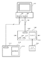
図1は、第1の実施形態におけるコピーシステムの構成を表すブロック図である。同図において、101はパーソナルコンピュータ(以下「パソコン」と略す)であり、この例ではディスプレイ一体型として説明する。また、OSには、例えばMicrosoft Windows 95又は98が搭載されているものとする。102はプリンタであり、ヘッド一体型のインクカートリッジを着脱可能なインクジェット記録方式のプリンタである。103はキャリッジであり、104のインクカートリッジか105のスキャナカートリッジが取り付けられるように構成されている。ここでインクカートリッジ104の代わりにスキャナカートリッジ105をキャリッジ103に取り付けることにより、プリンタ102はスキャナ機能を有するプリンタになる(以下、102をスキャナプリンタと称す)。106、107は双方向パラレルインタフェースのポートであり、108のパラレルインタフェースケーブルを介してパソコン101とスキャナプリンタ102との間で双方向パラレル通信が行われる。
【0022】
109はカートリッジ交換ボタンであり、インクカートリッジ104又はスキャナカートリッジ105を交換する時に押下される。このボタンが押下されるとキャリッジ103が不図示のカートリッジ交換ポジションに移動し、この状態でユーザがカートリッジの交換を自由に行うことができる。110は検出センサーであり、記録紙又は原稿を検出する。具体的には、インクカートリッジ104がキャリッジ103に搭載されているプリンタモードの時には記録紙の有無を検出し、スキャナカートリッジ105がキャリッジ103に搭載されているスキャナモードの時には原稿の有無を検出する(紙パスは同一である)。
【0023】
尚、キャリッジ103は図中のX−Y方向に移動し、記録又は読み取り動作を行う。また、本実施形態においては、キャリッジ103にはインクカートリッジ104が取り付けられているものとする。
【0024】
112は102と同様な構成を持つスキャナプリンタであり、102と異なる部分はインタフェースにUSB(Universal Serial Bus)を利用している部分だけである。また、112はヘッド一体型のインクカートリッジ104を着脱可能なインクジェット記録方式のプリンタであり、インクカートリッジ104はキャリッジ113に取り付けられるように構成されている。更に、インクカートリッジ104の代わりにスキャナカートリッジ105をキャリッジ113に取り付けることにより、スキャナ機能を有するスキャナプリンタになる。116、117はUSBインタフェースのポートであり、118のUSBインタフェースケーブルを介してパソコン101とスキャナプリンタ112との間で双方向通信が行われる。
【0025】
119はカートリッジ交換ボタンであり、インクカートリッジ104又はスキャナカートリッジ105を交換する時に押下される。このボタンが押下されるとキャリッジ113が不図示のカートリッジ交換ポジションに移動し、この状態でユーザがカートリッジの交換を自由に行うことができる。120は検出センサーであり、記録紙又は原稿を検出する。具体的には、インクカートリッジ104がキャリッジ113に搭載されているプリンタモードの時には記録紙の有無を検出し、スキャナカートリッジ105がキャリッジ113に搭載されているスキャナモードの時には原稿の有無を検出する(紙パスは同一である)。
【0026】
尚、キャリッジ113は図中のX'−Y'方向に移動し、記録又は読み取り動作を行う。また、本実施形態においては、キャリッジ113にはスキャナカートリッジ105が取り付けられているものとする。
【0027】
図2は、スキャナプリンタ102の詳細な構成を表すブロック図である。同図において、201はマイクロプロセッサなどから構成されるCPUであり、後述するプログラムに従って全体を制御する。202はROMであり、CPU201のプログラムや制御データ等が記憶されている。203はRAMであり、CPU201が処理を実行時に使用する作業領域や各種テーブル等が定義されたメモリである。また、RAM203はパソコン101から送信されてきた記録データ、又はスキャナカートリッジ105を介して後述する読取制御部により制御されて読み込まれ、キャリッジ制御部から送られてきた画像データも格納する。
【0028】
204は不揮発性RAMであり、スキャナプリンタ102の電源(本実施形態において電源部は省略してある)が遮断された状態にあっても、ユーザデータやその他の保存しておくべき最重要データ(例えば、インクカートリッジ104のインク残量データ等)を確実に格納するものである。205はキャラクタジェネレータ(CG)であり、JISコード、ASCIIコードなどのキャラクタや各種フォントを格納するROMで構成され、CPU201の制御に基づき必要に応じて1バイト又は2バイトのデータで所定コードに対応するキャラクタデータを出力する。
【0029】
206は操作部であり、不図示の電源スイッチやリセットスイッチ及び図1に示すカートリッジ交換ボタン109等から構成され、ユーザにより自由に操作が可能である。207は通信部であり、図1に示すポート107(117)を含み、Standard Signaling Method for a Bi-directional Parallel Peripheral Interface for Personal Computersの規格であるIEEE P1284に準拠して、パソコン101とスキャナプリンタ102との間の双方向パラレル通信を制御する。
【0030】
208はキャリッジ制御部であり、キャリッジ103に取り付けられたカートリッジに応じて後述する読取制御部又は記録制御部での動作を制御する。具体的には、カートリッジがインクカートリッジ104かスキャナカートリッジ105かをカートリッジに記憶されているIDを検出して判別し、インクカートリッジ104が搭載されている場合には後述する記録制御部が記録動作の制御を行い(プリンタモード)、スキャナカートリッジ105が搭載されている場合には後述する読取制御部が読取動作の制御を行う(スキャナモード)。209は表示部であり、不図示のLED、ブザー等から構成され、記録又は読取動作時のスキャナプリンタ102の状態をユーザに知らせる。
【0031】
210は読取制御部であり、不図示のDMAコントローラ、画像処理IC、CMOSロジックICなどから構成され、CPU201の制御に基づいてスキャナカートリッジ105を利用して読み取られたデータを多値化又は2値化し、そのデータを順次RAM203に送る。211は記録制御部であり、不図示のDMAコントローラ、インクジェット記録制御IC、CMOSロジックICなどから構成され、CPU201の制御によりRAM203に格納されている記録データを取り出し、ハードコピーとして記録出力する。尚、キャリッジ制御部208には図1に示す検出センサー110が有り、記録紙、原稿の有無を検出し、その状態により記録又は読み取りの制御が行われる。
【0032】
尚、図1に示すスキャナプリンタ112の構成は、図2に示す双方向パラレルインタフェースポート107がUSBインタフェースポート117に置き換わるだけであるので、その説明は省略する。但し、そのポート117は通信部207に含まれ、通信部207がUniversal Serial Bus(USB)の規格に準拠して、パソコン101とスキャナプリンタ112との間の双方向通信を制御する。
【0033】
図3は、本実施形態によるコピーアプリケーションの構成を表すブロック図である。尚、コピーアプリケーションは、パソコン101上のアプリケーションとしてOSによって起動されるものであるが、一般にアプリケーションを起動する構成及び動作は公知であり、その詳細については省略する。
【0034】
本実施形態では、コピーアプリケーションのプログラムコードは、CD−ROM等記憶媒体によりパソコン101へ供給されるものとする。ただし、本発明はこれに限るものではなく、例えば、パソコン101がネットワーク機能を有している場合は、接続されたネットワーク上に存在する所定の装置(サーバ装置等)から、プログラムコードをダウンロードすることにより供給することができる。
【0035】
また、供給されたコピーアプリケーションのプログラムは、パソコン101のハードディスクドライブ(図示せず)に予め格納されている。そして、OSによる起動に伴い、コピーアプリケーションのプログラムが実行され、図3の各モジュールが、パソコン101のRAM上に存在することになる。
【0036】
図3において、301はコピーアプリケーションであり、詳細は後述するUIマネージャ、スキャナドライバ、プリンタドライバから構成される。スキャナドライバ303は、スキャナプリンタ112のスキャナ機能を用いた画像の読み取り動作及び読み取られた画像の画像処理等を制御する。プリンタドライバ304は、スキャナプリンタ102のプリンタ機能を用いて画像の印刷動作及び画像処理等を制御する。スキャナドライバ303及びプリンタドライバ304は、予めパソコン101内の図示しないハードディスク等記憶装置に格納されている。コピーアプリケーション301は、スキャナドライバ303及びプリンタドライバ304を介してスキャナプリンタ112及び102を制御可能であり、原稿をコピーしてプリンタにて印刷する機能を有する。尚、コピーを行う際の設定に関しては後述する。
【0037】
302はUIマネージャであり、ユーザとのインタフェース(後述するメインダイアログボックス)を有し、及びこれを制御する。また、UIマネージャ302は、スキャナドライバ303及びプリンタドライバ304を介して、スキャナプリンタ102、112を制御するモジュールである。また、UIマネージャ302は、ユーザによる操作入力情報、及びスキャナドライバ303やプリンタドライバ304からの情報を基に、ユーザインタフェース及びスキャナプリンタ102、112を制御する。308はデバイス共有情報部であり、図4で後述される原稿サイズ選択部404で選択されている原稿サイズの情報、記録紙サイズ選択部405で選択されている用紙サイズ(記録紙サイズ)の情報が格納されている。また、デバイス共有情報部308には、図5で後述される読取設定及び記録(印刷)設定の情報をテーブル(データベース)化した情報、プレスキャン時の読取解像度情報が格納されている。デバイス共有情報部308に格納されている情報は、UIマネージャ302、スキャナドライバ303、プリンタドライバ304間で共有される。尚、デバイス共有情報部308は構造体であり、デバイス共有情報部308が格納する各種設定情報の実データの存在する場所は特に限定しない。つまり、実データは、パソコン101が有するHDDに格納されるものであっても、パソコン101が有するRAM上に一時的に格納されるものであってもよい。
【0038】
305はUSBインタフェースポート116、パラレルインタフェースポート106を制御するポートドライバであり、OSから提供されているモジュールである。また、USBポートドライバ306、パラレルポートドライバ307から構成され、USBポートドライバ306、パラレルポートドライバ307はUIマネージャ302の指示に従ってそれぞれUSBインタフェースポート116、パラレルインタフェースポート106を制御してデータの送受信を行う。
【0039】
図4は、ユーザインタフェースであるメインダイアログボックスの一例を表す図である。同図において、401はメインダイアログボックスであり、ユーザの操作によりスキャナプリンタ102,112における各設定等を確定してコピー動作を起動又は停止する等の操作を行う。メインダイアログボックス401はパソコン101が有するディスプレイに表示され、ユーザは、ディスプレイに表示されたメインダイアログボックス401の各種ボタンをマウス等ポインティングデバイスを用いて指定する(クリックする)ことにより様々な操作入力を行う。この例では、プレビュー領域402、読取範囲403、原稿サイズ選択部404、記録紙サイズ選択部405、DTP(カラー)ボタン411、DTP(モノクロ)ボタン412、写真ボタン413、FAXボタン414、OCRボタン415、テキストボタン416、画像サイズ表示部406、コピー部数指定部407、コピーボタン408、プレスキャンボタン409、キャンセルボタン410とから構成される。
【0040】
プレビュー領域402には、プレスキャン画像やコピー時に読み込まれた画像が表示される。読取範囲403は実際の読み取り範囲を読み取り可能な範囲内で任意に設定するための範囲指定ツールである。原稿サイズ選択部404はポップアップメニューで構成され、読み取られる原稿サイズをハガキ(100×148mm)、A5(148×210mm)、A4(210×297mm)、A3(297×420mm)、B5(182×257mm)、B4(257×364mm)の中から任意に選択可能である。図4の例では、A4(210×297mm)が選択されている。
【0041】
記録紙サイズ選択部405はポップアップメニューで構成され、記録(印刷)される用紙サイズをハガキ(100×148mm)、A5(148×210mm)、A4(210×297mm)、A3(297×420mm)、B5(182×257mm)、B4(257×364mm)の中から任意に選択可能である。図4の例では、A4(210×297mm)が選択されている。画像サイズ表示部406には読取範囲403で指定された横×縦の長さ(センチメートル単位)が表示されている。コピー部数指定部407はテキストフィールド及びスピンボタンで構成され、一組の原稿に対するコピー(印刷)部数を1〜99枚の範囲で任意に指定することができる。
【0042】
尚、原稿サイズ選択部404で選択される原稿サイズ、及び記録紙サイズ選択部405で選択される用紙サイズに基づき、複写倍率が決定される。コピーを行う際、コピーアプリケーション301は、スキャナプリンタ112から受信した画像を、決定した複写倍率に基づき変倍し、変倍した画像をスキャナプリンタ102に送信する。例えば、原稿サイズとしてB5が選択され、用紙サイズとしてA4が選択されると、複写倍率は115%と決定される。このとき、コピーアプリケーション301は、受信画像に対して115%の拡大処理を行う。
【0043】
411〜416はクリックされると、そのボタン一つが選択(ハイライト)されるボタンであり、選択(ハイライト)された状態においてコピーボタン408又はプレスキャンボタン409がクリック(押下)された場合にその意味を発揮する。図4の例では、写真ボタン413が選択(ハイライト)されている状態である。これらのボタンはコピー目的(コピーの際のモード)を表すボタンであり、これらのボタンの意味の詳細は後述する。
【0044】
キャンセルボタン410はコピー動作又はプレスキャン動作をキャンセルするためのボタンであり、コピー動作中又はプレスキャン動作中のみ有効で、それ以外の場合はグレーアウトしている。また、コピー動作中又はプレスキャン動作中にキャンセルボタン410がクリック(押下)された場合、コピー動作又はプレスキャン動作を中断し、スタンバイ状態に戻る。
【0045】
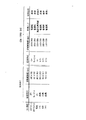
図5は、コピー目的を表すボタン411〜416が意味する読取設定及び記録(印刷)設定を表す図である。図示するように、それぞれのコピー目的に対して読取設定、記録(印刷)設定が設定される。つまり、スキャナドライバ303を介してスキャナカートリッジ105が搭載されているスキャナプリンタ112に対して読取方式、読取解像度の読取設定が設定され、プリンタドライバ304を介してインクカートリッジ104が搭載されているスキャナプリンタ102に対して記録方式、記録解像度、記録メディア、記録品位の記録(印刷)設定が設定される。ここで、記録品位とは、スキャナプリンタ102における記録動作に係る設定であり、例えば、インクカートリッジ104からのインクの吐出量や、パスの回数(紙面上の同一領域を走査する回数)等が設定される。
【0046】
例えば、写真ボタン413が選択された状態でコピーボタン408がクリックされた場合は、写真モードでのコピーが選択されたことを意味し、スキャナプリンタ112に対して、読取方式“カラー”、読取解像度“360×360dpi”の読取設定が行われ、スキャナプリンタ102に対して記録方式“カラー”、記録解像度“360×360dpi”、記録メディア“高品位専用紙”、記録品位“高品位”の記録(印刷)設定が行われる。
【0047】
また、例えば写真ボタン413が選択された状態でプレスキャンボタン409がクリックされた場合はスキャナプリンタ112に対して読取方式“カラー”、読取解像度“90×90dpi”の読取設定が行われ、スキャナプリンタ102に対して記録(印刷)設定は行われない。ここで、読取解像度として図5に示す“360×360dpi”ではなく、“90×90dpi”が設定されるのは、プレスキャン時は読み取りの速度を早くするために、全てのコピー目的において読取解像度を“90×90dpi”と設定するからである。また、スキャナプリンタ102に対して何も設定しないのは、プレスキャン時点では記録動作が行われないため、記録に関する設定を行う必要がないからである。即ち、本実施形態では、プレスキャンボタン409がクリックされた時に有効となる値は読取方式だけである。
【0048】
このように、図5に示す設定は411〜416の各ボタンにプリセットされている、読取設定及び記録(印刷)設定の設定値を表すものであるといえる。また、操作者は各ボタン411〜416のいずれかを選択することにより、読取設定及び記録(印刷)設定を同時にできるので、操作者は目的ボタン411〜416を用いて、複写の目的に応じた複写モードを選択することができるともいえる。このとき、図5に示す設定値は各複写モードに対応している。これらの設定値は、同図に示されている通り、411〜416の各ボタン(各複写モード)に割り当てられてテーブル(データベース)化された情報として、デバイス共有情報部308に格納されている。そして、コピーボタン408又はプレスキャンボタン409がクリック(押下)された時、UIマネージャ302は、デバイス共有情報部308に格納されている、選択(ハイライト)されているボタン(411〜416の内の何れか一つのボタン)に割り当てられている情報と、原稿サイズ選択部404で選択されている原稿サイズの情報と、記録紙サイズ選択部405で選択されている用紙サイズ(記録紙サイズ)の情報と、プレスキャン時の読取解像度情報(90×90dpi)とを、デバイス共有情報部308から取得し、これらの情報をスキャナドライバ303及びプリンタドライバ304に通知する。スキャナドライバ303、プリンタドライバ304は、UIマネージャ302から渡されたこれらの情報に従って、スキャナプリンタ102、112を制御する。
【0049】
尚、図5に示す記録メディアの指定は、指定されたメディアに最適な画像処理をすることを表しており、指定されたメディアをユーザがセットしていることを前提としている。
【0050】
また、読取方式の“カラー”はR(レッド)、G(グリーン)、B(ブルー)多値で、“グレースケール”は白黒多値で、“白黒”は白黒2値で読み取る設定を意味しており、また記録方式の“カラー”はC(シアン)、M(マゼンタ)、Y(イエロー)、K(ブラック)多値で、“グレースケール”は黒(ブラック)多値で、“モノクロ”は黒(ブラック)2値で印刷する設定を意味している。
【0051】
次に、図6乃至図9を参照して本実施形態におけるコピーアプリケーションの処理を説明する。
【0052】
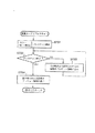
図6は、コピーアプリケーション301におけるスタンバイ状態の処理を表すフローチャートである。まずステップS601において、UIマネージャ302がスタンバイ状態で各イべントの発生を監視する。そして、ステップS602において、例えばコピーボタン408がクリック(押下)されたなどのイべントが発生した場合はステップS603へ進み、その発生したイベントに適応した処理を行い、上述のステップS601へ戻る。
【0053】
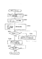
図7は、図6に示すステップS603でのイベント処理を示すフローチャートである。この例は、写真ボタン413が選択(ハイライト)された状態でプレスキャンボタン409がクリック(押下)された時(複写モードが写真モードでプレスキャン)の処理を表すものである。また、原稿としてはカラー写真が準備されているものとする。
【0054】
まず、ステップS701において、写真モードのプレスキャンの場合、図5に示した、デバイス共有情報部308に格納されている読取設定の情報及びプレスキャン時の読取解像度情報に従って、読取方式“カラー”、読取解像度“90×90dpi”の設定をスキャナプリンタ112に対して設定し、プレスキャンを開始する。そして、ステップS702において、プレスキャンが終了したか判断し、終了でなければステップS703へ進み、その時点迄に読み取られた分の画像を随時プレビュー領域402に表示する。その後、プレスキャンが終了したならば、ステップS704へ進み、読み取られた全画像をプレビュー領域402に表示し、このイベント処理を終了する。
【0055】
図8は、図6に示すステップS603でのイベント処理を示すフローチャートである。この例は、写真ボタン413が選択(ハイライト)された状態でコピーボタン408がクリック(押下)された時(複写モードが写真モードでコピー)の処理を表すものである。また、原稿としてはカラー写真が準備されているものとする。
【0056】
まず、ステップS801において、写真モードでコピーの時、原稿サイズ選択部404、記録紙サイズ選択部405で選択されて、デバイス共有情報部308に格納されている原稿サイズの情報、用紙サイズ(記録紙サイズ)の情報に従って、原稿サイズと記録紙サイズとからコピー倍率を設定する。具体的には図4に示す例では原稿サイズと記録紙サイズとが共にA4(210×297mm)であるので、倍率100%である。次に、ステップS802において、UIマネージャ302は、デバイス共有情報部308に格納されている読取設定の情報を取得し、取得した読取設定を受けたスキャナドライバ303はこれに従って、図5に示す読取方式“カラー”、読取解像度“360×360dpi”の設定をスキャナプリンタ112に対して設定し、コピー読み取りを開始する。そして、ステップS803において、UIマネージャ302は、デバイス共有情報部308に格納されている記録(印刷)設定の情報を取得し、取得した記録(印刷)設定を受けたプリンタドライバ304はこれに従って、図5に示す記録方式“カラー”、記録解像度“360×360dpi”、記録メディア“高品位専用紙”、記録品位“高品位”の設定もスキャナプリンタ102に対して設定し、コピー記録(印刷)を開始する。
【0057】
次に、ステップS804において、コピー読み取りが終了したか判断し、終了でなければステップS805へ進み、その時点迄に読み取られた分の画像を随時プレビュー領域402に表示する。その後、コピー読み取りが終了したならばステップS806へ進み、読み取られた全画像をプレビュー領域402に表示する。そして、ステップS807において、コピー部数指定部407で指定された部数分のコピー記録(印刷)が終了したか判断し、終了していなければコピー記録(印刷)を繰り返し、コピー記録(印刷)が終了したならば、このイべント処理を終了する。
【0058】
尚、図8に示す処理は、写真ボタン413が選択(ハイライト)された状態でコピーボタン408がクリック(押下)された時(複写モードが写真モードでコピー)の処理であるが、スキャナプリンタ112だけがパソコン101に接続され、スキャナプリンタ102が存在しない場合も考えられる。以下、このような場合の処理について説明する。
【0059】
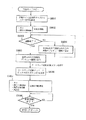
図9は、スキャナプリンタ112だけがパソコン101に接続されている場合に、写真ボタン413が選択(ハイライト)された状態でコピーボタン408がクリック(押下)された時(複写モードが写真モードでコピー)の処理を表すフローチャートである。
【0060】
まず、ステップS901において、写真モードでコピーの時、原稿サイズ選択部404、記録紙サイズ選択部405で選択されて、デバイス共有情報部308に格納されている原稿サイズの情報、用紙サイズ(記録紙サイズ)の情報に従って、原稿サイズと記録紙サイズとからコピー倍率を設定する。具体的には図4に示す例では原稿サイズと記録紙サイズとが共にA4(210×297mm)であるので、倍率100%である。次に、ステップS902において、UIマネージャ302がデバイス共有情報部308に格納されている読取設定の情報を取得し、取得した読取設定を受けたスキャナドライバ303はこれに従って、図5に示す読取方式“カラー”、読取解像度“360×360dpi”の設定をスキャナプリンタ112に対して設定し、コピー読み取りを開始する。
【0061】
次に、ステップS903において、コピー読み取りが終了したか判断し、終了でなければステップS904へ進み、その時点迄に読み取られた分の画像を随時プレビュー領域402に表示する。その後、コピー読み取りが終了したならばステップS905へ進み、読み取られた全画像をプレビュー領域402に表示する。そして、ステップS906において、例えば図10に示すようなカートリッジ交換メッセージボックス1001を表示し、キャリッジ103のカートリッジがスキャナカートリッジ105からインクカートリッジ104に交換され、ユーザによって「OK」ボタン1002がクリック(押下)されるのを待つ。
【0062】
この「OK」ボタン1002がクリック(押下)されるとステップS907へ進み、UIマネージャ302は、デバイス共有情報部308に格納されている記録(印刷)設定の情報を取得し、取得した記録(印刷)設定を受けたプリンタドライバ304はこれに従って、図5に示す記録方式“カラー”、記録解像度“360×360dpi”、記録メディア“高品位専用紙”、記録品位“高品位”の設定をスキャナプリンタ112に対して設定し、コピー記録(印刷)を開始する。その後、ステップS908において、コピー部数指定部407で指定された部数分のコピー記録(印刷)が終了するまでコピー記録(印刷)を繰り返し、コピー記録(印刷)が終了すると、このイベント処理を終了する。
【0063】
以上説明した実施形態によれば、コピー目的を意味する411〜416のそれぞれのボタンに対して、予め読取設定、記録(印刷)設定を各々の目的に応じてプリセットしておき、コピー目的ボタン411〜416を用いることで複写モードとして選択できるようにしている。そして、コピー目的ボタン411〜416の内の何れかのボタンが選択された状態でコピーボタン408がクリック(押下)されると、その複写モードに対応した読取設定で原稿を読み取り、且つその記録(印刷)設定で記録(印刷)するので、原稿に応じたコピーを容易な操作で、且つ高品位に行うことが可能となる。
【0064】
これにより、例えば原稿が一般のテキスト文書の場合は高速、且つ標準品位でコピーが行われ、また原稿がカラー写真の場合は高解像度、且つ高品位でコピーが行われるというように、目的に応じたコピーを時間の無駄無く、容易な操作で確実に得ることが可能となる。
【0065】
また、プレスキャンすることが可能なため、そのプレビュー領域402に表示されたプレスキャン画像を基に読取範囲403で設定された範囲内だけをコピーすることが可能となり、必要な部分のみを時間の無駄無く、容易な操作でコピーすることも可能となる。更に、プレスキャン時の読取解像度はプリセットされている読取解像度に関わらず、装置が持っている読取解像度の能力の中でも比較的低い解像度(本実施形態では“90×90dpi”)で行うため、プレスキャンを高速に行うことが可能となる。
【0066】
尚、本実施形態では、例としてOSにMicrosoft Windows 95又は98を使用したが、このOSに限られることなく、同様な構成をとることにより、任意のOSにおいて実現可能である。
【0067】
また、本実施形態では、例としてパソコン101とスキャナプリンタ102との間のインタフェースに、Standard Signaling Method for a Bi-directional Parallel Peripheral Interface for Personal Computersの規格であるIEEEP1284に準拠したパラレルインタフェースを用いたが、このインタフェースに限られることなく、同様な構成をとることにより、任意のインタフェースにおいて実現可能である。
【0068】
また、本実施形態では、例としてパソコン101とスキャナプリンタ112との間のインタフェースに、USB(universal Serial Bus)インタフェースを用いたが、このインタフェースに限られることなく、同様な構成をとることにより、任意のインタフェースにおいて実現可能である。
【0069】
本実施形態では、スキャナの例としてスキャナプリンタ112を用いたが、本発明は、これに限られることなく、特にプリンタ機能を備えるものではなくても一般の任意のスキャナを代用することにより実現可能である。
【0070】
同様に、プリンタの例としてスキャナプリンタ102を用いたが、本発明は、これに限られることなく、特にスキャナ機能を備えるものではなくても一般の任意のプリンタを代用することにより実現可能である。
【0071】
また、デジタル複写機等、スキャナ部とプリンタ部を一体的に構成している画像処理装置を用いることもできる。つまり、デジタル複写機のスキャナ機能のみを用い、プリンタは他の任意のプリンタを用いたコピーシステムおいても本発明は適用可能である。同様に、スキャナは任意のスキャナを用いて、プリンタとしてデジタル複写機のプリンタ機能を用いたコピーシステムにおいても本発明は適用可能である。
【0072】
以上説明したように、本実施形態では、スキャナに準備された原稿をコピーしてプリンタで印刷するコピー機能を制御するコピーアプリケーションが、ユーザインタフェースとして複数のコピー目的選択ボタンとコピースタートボタンとを用意している。コピー目的選択ボタンには、それぞれのボタンに対して、スキャナに対して設定する読取設定と、プリンタに対して設定する印刷設定とが割り当てられている。コピー目的選択ボタンの内のある一つのボタンが選択された状態で、コピースタートボタンが押下された場合、スキャナに対して選択されているボタンに割り当てられている読取設定を設定し、この設定に基づいて原稿の読み取りを行い、プリンタに対して選択されているボタンに割り当てられている印刷設定を設定し、この設定に基づいて読み取られた画像を印刷するように構成した。
【0073】
これにより、原稿に応じた原稿のコピーを容易な操作で、且つ高品位に行うことが可能となるという効果が得られる。また、例えば、原稿が一般のテキスト文書の場合は高速、且つ標準品位でコピーが行われ、また原稿がカラー写真の場合は高解像度、且つ高品位でコピーが行われるというように、目的に応じたコピーを時間の無駄無く、容易な操作で確実に得ることが可能となるという効果が得られる。
【0074】
また、本実施形態においては、アプリケーションのユーザインタフェースとして、プレスキャンボタンと、読取られた画像を表示するプレビュー領域と、読み取りの範囲を指定する読取範囲指定手段とを用意した。
【0075】
これにより、プレスキャンが可能であるため、プレビュー領域に表示されたプレスキャン画像に基づき、読取範囲指定手段で指定された範囲内だけをコピーすることが可能であるので、必要な部分のみを時間の無駄無く容易な操作でコピーすることが可能となるという効果が得られる。
【0076】
また、本実施の形態においては、プレスキャン時の読取解像度は、コピー目的選択ボタンに割り当てられている読取解像度に関わらず装置が持っている読取解像度能力の中において比較的低い解像度を利用して行うため、プレスキャンを高速に行うことが可能となるという効果が得られる。
【0077】
本実施の形態においては、着脱可能なスキャナカートリッジ及びインクカートリッジを備えるスキャナプリンタを用いており、一台のプリンタ(スキャナプリンタ)のみをホストコンピュータに接続していてもコピーシステムを構成することができるので、全く同様な構成で上述した全ての効果を得ることができる。また、この場合、スキャナ及びプリンタがそれぞれ独立して存在する必要がないので、設置スペースが小さくて済み、場所を選ばず容易にコピーシステムが実現可能となる。
【0078】
(第2の実施形態)
これまで説明してきた第1の実施形態では、スキャナの例としてスキャナプリンタ112を用いたが、本発明は、これに限られることなく、特にプリンタ機能を備えるものではなくても一般の任意のスキャナを代用することにより実現可能である。
【0079】
同様に、第1の実施形態では、プリンタの例としてスキャナプリンタ102を用いたが、本発明は、これに限られることなく、特にスキャナ機能を備えるものではなくても一般の任意のプリンタを代用することにより実現可能である。
【0080】
本実施形態では、任意のスキャナ及びプリンタを用いた場合のコピーシステムの一例を説明する。
【0081】
図11に本実施形態のコピーシステムの構成を表すブロック図を示す。同図において、101はパソコンであり、第1の実施形態で説明したパソコンと同じものである。1102はプリンタであり、ヘッド一体型のインクカートリッジを着脱可能なインクジェット記録方式のプリンタである。106、1107は双方向パラレルインタフェースのポートであり、108のパラレルインタフェースケーブルを介してパソコン101とプリンタ1102との間で双方向パラレル通信が行われる。
【0082】
1109はカートリッジ交換ボタンであり、インクカートリッジ1104を交換する時に押下される。このボタンが押下されるとキャリッジ1103が不図示のカートリッジ交換ポジションに移動し、この状態でユーザがカートリッジの交換を自由に行うことができる。1110は検出センサーであり、記録紙を検出する。具体的には、インクカートリッジ1104がキャリッジ1103に搭載されている時に記録紙の有無を検出する。 尚、キャリッジ1103は図中のX−Y方向に移動し、記録動作を行う。
【0083】
1112はスキャナであり、プリンタ1102と異なりインタフェースにUSB(Universal Serial Bus)を利用している。116、1117はUSBインタフェースのポートであり、118のUSBインタフェースケーブルを介してパソコン101とスキャナ1112との間で双方向通信が行われる。1113は、読み取り原稿をセットするための原稿台や、原稿画像を読み取るためのCCDセンサー等を含む読取部である。
【0084】
プリンタ1102の内部構成は、図2に示されるスキャナプリンタの構成ブロックから、スキャナ動作のための機能を除いたものとして説明できる。また、スキャナ1112の内部構成についても、図2に示されるスキャナプリンタの構成ブロックから、プリンタ動作のための機能を除いたものとして説明できる。
【0085】
本実施形態においては、第1の実施形態と同様に、スキャナドライバ303はスキャナ1112を制御可能であり、プリンタドライバ304はプリンタ1102を制御可能である。また、パソコン101には、予めスキャナドライバ303とプリンタドライバ304が格納されているものとする。
【0086】
スキャナ1112単体を用いて原稿の読み取りを行いたい時は、スキャナドライバ303を起動することにより、スキャナ1112による画像読み取りが制御可能となる。
【0087】
スキャナドライバ303は、原稿の読み取り操作を行うためのダイアログボックス(図示せず)をディスプレイに表示することができ、操作者は、ダイアログボックスから読み取りモードを選択することができる。ここで、スキャナドライバ303は、図12のテーブル1201に示す6つの読み取りモードに基づく動作を行うことができる。また、第1の実施形態と同様に、ダイアログボックスには、読み取り目的ボタンを各読み取りモードに対応させて表示し、操作者に選択可能とするように構成してもよい。
【0088】
ここで、例えば、読み取りモード“DTP(カラー)”を選択し、読み取り開始指示を出すと、スキャナドライバ303はこの選択を受け、テーブル1201を参照する。そして対応する読み取り設定である、読取方式“カラー”、読取解像度(dpi)“180×180”に従い、USBインターフェースケーブル118を介して、スキャナ1112を制御する。スキャナ1112は、上述の読み取り設定に基づき原稿を読み取り、読み取った画像をパソコン101へ送信する。
【0089】
一方、プリンタ1102単体を用いて画像の印刷を行いたい時は、プリンタドライバ304を起動することにより、プリンタ1102による画像の印刷が制御可能となる。
【0090】
プリンタドライバ304は、画像の印刷操作を行うためのダイアログボックス(図示せず)をディスプレイに表示することができ、操作者は、ダイアログボックスから印刷モードを選択することができる。ここで、プリンタドライバ304は、図12のテーブル1202に示す6つの印刷モードに基づく動作を行うことができる。また、第1の実施形態と同様に、ダイアログボックスには、印刷目的ボタンを各印刷モードに対応させて表示し、操作者に選択可能とするように構成してもよい。
【0091】
例えば、印刷モード“DTP(カラー)”を選択し、印刷開始指示を出すと、プリンタドライバ304はこの選択を受け、テーブル1202を参照する。そして対応する印刷設定である、記録方式“カラー”、記録解像度(dpi)“180×180”に従い、パラレルインタフェースケーブル108を介して、プリンタ1102を制御する。プリンタ1102は、上述の印刷設定に基づきパソコン101から入力した画像を印刷する。
【0092】
次に、本実施形態のコピーシステムについて詳細に説明する。本実施形態のコピーシステムは、パソコン101において、コピーアプリケーションを用いることにより実現される。このコピーアプリケーションのブロック構成は図3に示すものと同じである。したがって、以下、コピーアプリケーションの説明は図3のブロック図を用いることにする。
【0093】
本実施形態のUIマネージャ302及びデバイス共有情報部308等、各モジュールは、第1の実施形態で説明したものと同様な機能を有している。ただし、本実施形態では、UIマネージャ302が、任意のスキャナ及びプリンタを用いたコピーシステムを実現可能とするためのテーブル生成機能を更に有している。以下、このテーブル生成機能について説明する。
【0094】
本実施形態のコピーシステムは、上述したスキャナ1112及びプリンタ1102を単体として利用可能な構成であり、スキャナドライバ303及びプリンタドライバ304は、それぞれテーブル1201及びテーブル1202を有している。
【0095】
スキャナ1112とプリンタ1102を用いてコピー動作を行う際は、これらのテーブルから、1つの読み取りモードと、1つの印刷モードをそれぞれ選択して複写開始指示を出すことができる。
【0096】
図12に示されるように、テーブル1201は6つの読み取りモードを有しており、テーブル1202は6つの印刷モードを有している。したがって、複数の読み取りモードと複数の印刷モードとを組み合わせて、計36通りの複写設定を行うことができる。しかし、これらの設定の中から適切な複写設定の組み合わせを選択する操作は煩雑なものになりやすく、選択操作ミスによる無駄なコピーを行ってしまうこともある。
【0097】
容易な操作で適切な複写が行えるようにするには、第1の実施形態で説明した複写モードを実現するためのテーブルをパソコン101が備えていればよい。しかし、本実施形態の様に任意のスキャナとプリンタを接続したシステムにおいては、そのようなテーブルをパソコン101が予め保持しているとは限らない。
【0098】
本実施形態では、任意のスキャナとプリンタを接続したシステムにおいても、容易な操作で適切な複写が行えるようにする。この目的を達成するために、本実施形態のコピーアプリケーション301は、これらの複数の読み取りモード及び印刷モードから複数の複写モードを生成する機能を備えている。
【0099】
以下、コピーシステムによる複写動作を行う際のコピーアプリケーション301による複写モード生成処理について詳細に説明する。
【0100】
まず、操作者によるコピーアプリケーション301の起動に応じて、UIマネージャ302がスキャナドライバ303及びプリンタドライバ304から読み取りモードのテーブル1201及び印刷モードのテーブル1202を取得する。
【0101】
次に、UIマネージャ302は、取得したテーブルから複写モードを生成する。ここで、生成方法は、例えば、各読み取りモードの名称(識別情報)と各印刷モードの名称(識別情報)を照らし合わせて、最も組み合わせとして適切な読み取りモードと印刷モードとを選択して生成する方法がある。
【0102】
例えば、テーブル1201の読み取りモード“写真”と、テーブル1202の印刷モード“写真”は、名称(識別情報)が一致している。したがって、読み取りモード名称(識別情報)“写真”及びそれに対応する設定情報1203と、印刷モード名称(識別情報)“写真”とそれに対応する設定情報1204とを用いて、写真の複写に適する写真モード名称(識別情報)“写真”とそれに対応する複写設定情報(読取設定情報と印刷設定情報)1205を生成することができる。
【0103】
図12の1206は、テーブル1201とテーブル1202から生成した複数の複写モードとそれぞれに対応した読取設定及び記録設定の情報を表すテーブルである。テーブル1206は、UIマネージャ302により生成され、デバイス共有情報部308に一旦格納される。
【0104】
UIマネージャ302は、格納されたテーブル1203の各複写モードを、メインダイアロクボックス401のコピー目的ボタン411〜416に対応させ、操作者により選択できるようにする。
【0105】
以上の処理により、複写モード(テーブル1206)の生成が終了する。この複写モードを用いた複写動作は第1の実施形態と同様に説明できる。
【0106】
また、生成したテーブル1206は、コピーアプリケーション301の動作終了後、パソコン101の図示しないハードディスクに格納するようにしてもよい。
【0107】
また、テーブル生成方法に関しては、スキャナドライバ及びプリンタドライバが、上述した読み取りモード及び印刷モードを有していない場合もあるので、上記の方法に限るものではなく、他の方法により生成されてもよい。
【0108】
また、本実施の形態では、任意のスキャナとプリンタを接続したコピーシステムの場合で、コピーアプリケーションによるテーブルの生成機能を説明してきたが、これに限るものではなく、第1の実施形態で説明したような、スキャナプリンタにより構成されるコピーシステムにおいても、コピーアプリケーションによるテーブルの生成機能が適用可能であることはいうまでもない。
【0109】
以上説明してきたように、本実施形態においては、任意のスキャナとプリンタを接続したコピーシステムにおいて、コピーアプリケーションに複写動作のためのテーブル生成機能を備えさせた。
【0110】
これにより、コピーアプリケーションが、複写モードとその設定情報を予め有していない場合でも、装置構成に応じた複写モードを生成し、生成した複写モードに基づくコピーが行えるようになるという効果が得られる。
【0111】
また、生成した複写モードは、メインダイアログボックスのコピー目的ボタンに対応させるので、容易な操作で適切な複写画像を得ることができるという効果が得られる。
【0112】
以上第1実施形態及び第2実施形態において本発明を説明してきたが、本発明は複数の機器(例えば、ホストコンピュータ,インタフェイス機器,リーダ,プリンタなど)から構成されるシステムに適用しても、一つの機器からなる装置(例えば、複写機,ファクシミリ装置など)に適用してもよい。
【0113】
また、本発明の目的は前述した実施形態の機能を実現するソフトウェアのプログラムコードを記録した記憶媒体を、システム或いは装置に供給し、そのシステム或いは装置のコンピュータ(CPU若しくはMPU)が記憶媒体に格納されたプログラムコードを読出し実行することによっても、達成されることは言うまでもない。
【0114】
この場合、記憶媒体から読出されたプログラムコード自体が前述した実施形態の機能を実現することになり、そのプログラムコードを記憶した記憶媒体は本発明を構成することになる。
【0115】
プログラムコードを供給するための記憶媒体としては、例えばフロッピーディスク,ハードディスク,光ディスク,光磁気ディスク,CD−ROM,CD−R,磁気テープ,不揮発性のメモリカード,ROMなどを用いることができる。
【0116】
また、コンピュータが読出したプログラムコードを実行することにより、前述した実施形態の機能が実現されるだけでなく、そのプログラムコードの指示に基づき、コンピュータ上で稼働しているOS(オペレーティングシステム)などが実際の処理の一部又は全部を行い、その処理によって前述した実施形態の機能が実現される場合も含まれることは言うまでもない。
【0117】
更に、記憶媒体から読出されたプログラムコードが、コンピュータに挿入された機能拡張ボードやコンピュータに接続された機能拡張ユニットに備わるメモリに書込まれた後、そのプログラムコードの指示に基づき、その機能拡張ボードや機能拡張ユニットに備わるCPUなどが実際の処理の一部又は全部を行い、その処理によって前述した実施形態の機能が実現される場合も含まれることは言うまでもない。
【0118】
【発明の効果】
以上説明したように、本発明によれば、読取装置及び印刷装置と接続され、読取装置による読み取り動作を制御するスキャナドライバと、スキャナドライバとは独立して動作し、印刷装置による印刷動作を制御するプリンタドライバとが保持された情報処理装置が、操作者により選択された複写モードに対応する読取設定情報及び印刷設定情報を取得し、選択された複写モードに対応する読取設定情報に基づいてスキャナドライバを動作させることにより、読取装置に原稿を読み取らせるとともに原稿を読み取って得た画像を送信させるよう制御し、選択された複写モードに対応する印刷設定情報に基づいてプリンタドライバを動作させることにより、読取装置から情報処理装置に送信された画像を印刷装置に印刷させるよう制御することにより、容易な操作で、複数の複写モードから操作者が選択した複写モードに応じた複写結果を得ることができる。
【図面の簡単な説明】
【図1】第1の実施形態におけるコピーシステムの構成を表すブロック図である。
【図2】スキャナプリンタ102の詳細な構成を表すブロック図である。
【図3】コピーアプリケーションの構成を表すブロック図である。
【図4】ユーザインタフェースであるメインダイアログボックスの一例を表す図である。
【図5】コピー目的を表すボタン411〜416が意味する読取設定及び記録(印刷)設定を表す図である。
【図6】コピーアプリケーション301におけるスタンバイ状態の処理を表すフローチャートである。
【図7】図6に示すステップS603でのイベント処理を示すフローチャートである。
【図8】図6に示すステップS603でのイベント処理を示すフローチャートである。
【図9】スキャナプリンタ112だけがパソコン101に接続されている場合に、写真ボタン413が選択(ハイライト)された状態でコピーボタン408がクリック(押下)された時(写真モードでコピー)の処理を表すフローチャートである。
【図10】カートリッジ交換メッセージボックス1001の表示を示す図である。
【図11】第2の実施形態におけるコピーシステムの構成を表すブロック図である。
【図12】第2の実施形態における、読み取り目的モード、印刷目的モード、コピー目的モード、及びそれぞれのモードのテーブルを説明するための図である。
【符号の説明】
101 パソコン
102 スキャナプリンタ
103 キャリッジ
104 インクカートリッジ
105 スキャナカートリッジ
106 双方向パラレルインタフェースのポート
107 双方向パラレルインタフェースのポート
108 パラレルインタフェースケーブル
109 カートリッジ交換ボタン
110 センサ
112 スキャナプリンタ
113 キャリッジ
116 USBインタフェースのポート
117 USBインタフェースのポート
118 USBインタフェースケーブル
201 CPU
202 ROM
203 RAM
204 不揮発性RAM
205 CG
206 操作部
207 通信部
208 キャリッジ制御部
209 表示部
210 読取制御部
211 記録制御部
301 コピーアプリケーション
302 UIマネージャ
303 スキャナドライバ
304 プリンタドライバ
305 ポートドライバ
306 USBポートドライバ
307 パラレルポートドライバ
308 デバイス共有情報部
401 メインダイアログボックス
402 プレビュー領域
403 読取範囲
404 原稿サイズ選択部
405 記録紙サイズ選択部
406 画像サイズ
407 コピー部数指定部
408 コピーボタン
409 プレスキャンボタン
411 DTP(カラー)ボタン
412 DTP(モノクロ)ボタン
413 写真ボタン
414 FAXボタン
415 OCRボタン
416 テキストボタン[0001]
BACKGROUND OF THE INVENTION
The present invention Reading Equipment and printing Connected with the device A scanner driver that controls a reading operation by the reading device and a printer driver that operates independently of the scanner driver and controls a printing operation by the printing device are held Information processing apparatus and information It relates to the processing method.
[0002]
[Prior art]
There is known an image processing system in which a scanner device having a function of reading an image and a printer device having a function of printing image data are connected to a host computer such as a personal computer via a communication medium. In particular, an image processing system capable of printing an image read by a scanner device with a printer device is called a copy system.
[0003]
In the copy system, settings and control related to image reading and printing are performed on a host computer. In recent years, a copy system has been proposed in which these settings, control, and the like are performed by software called a copy application. The copy application can display copy information on the screen of a display or display a user interface for an operator to perform a copy operation on the display of the host computer. With respect to operations on the displayed user interface, copying can be performed by a simple operation such as setting the number of copies and pressing a copy button.
[0004]
[Problems to be solved by the invention]
However, in the above-described conventional copy application, in order to simplify the operation, settings relating to reading and settings relating to printing are performed using predetermined setting values, and reading and printing are performed based on these setting values. Is going. For this reason, copying is performed at a certain copy speed and copy image quality regardless of the type of document.
[0005]
Usually, in order to improve the quality of a copy image to be printed, it is necessary to read with high resolution and high quality multi-value, and to print with high resolution and high quality. For this reason, the number of data to be processed increases, and the copy speed is greatly reduced. Further, in order to improve the printing speed, it is necessary to read with low resolution and low quality binary, and to print with low resolution and low quality, so the quality of the printed copy image is greatly reduced.
[0006]
Therefore, in the conventional copy system, when setting a predetermined set value, the quality of the copy image to be printed and the copy speed are balanced, and an intermediate value between the two is set. In other words, the setting relating to reading is set to medium resolution and standard quality multivalue, and the setting relating to printing is set to medium resolution and standard quality.
[0007]
For this reason, for example, when a simple text document is copied, it may take more time than necessary to copy one original. In addition, when a color photograph is copied, the printed image quality may be significantly deteriorated with respect to the original color photograph.
[0008]
In order to prevent such an increase in copy time and deterioration in image quality, settings relating to reading and settings relating to printing may be performed in accordance with the document. However, in the conventional copy application, settings relating to the reading operation are performed on the user interface displayed by the scanner driver that drives the scanner device, and settings relating to printing are performed on the user interface displayed by the printer driver that drives the printer device. It is comprised so that it may be performed.
[0009]
That is, there is a problem that the user needs a complicated operation even though only copying, and the operability becomes very poor. Furthermore, the user may not be able to set an expected setting value by erroneously performing an operation on a setting relating to reading or a setting relating to printing. In this case, there arises a problem that the copy speed is unnecessarily slow or the quality of the printed copy image becomes unexpectedly poor.
[0010]
The present invention is for solving the above-described problems, and provides an information processing apparatus, an image processing method, a storage medium, and a program capable of obtaining a high-quality image processing result with an easy operation. Objective.
[0011]
Another object of the present invention is to provide an information processing apparatus, an image processing method, a storage medium, and a program that can execute image processing at an appropriate processing speed with an easy operation.
[0012]
Another object of the present invention is to provide an information processing apparatus, an image processing method, a storage medium, and a program that can obtain image processing results flexibly corresponding to various apparatus configurations.
[0013]
Another object of the present invention is to provide a storage medium and a program capable of obtaining a high-quality copy result with an easy operation.
[0014]
Another object of the present invention is to provide a storage medium and a program capable of executing copying at an appropriate processing speed with an easy operation.
[0015]
Another object of the present invention is to provide a storage medium and a program capable of obtaining a copy result flexibly corresponding to the configuration of the scanner and printer.
[0016]
[Means for Solving the Problems]
In order to achieve the above object, the present invention provides a scanner driver that is connected to a reading device and a printing device, and controls a reading operation by the reading device, and operates independently of the scanner driver, and printing by the printing device. An information processing apparatus having a printer driver for controlling operation, wherein the information processing apparatus has a plurality of copying modes, and each of the plurality of reading setting information and the plurality of printing setting information for each copying mode. Multiple copy modes that are associated with each other Along with the plurality of reading setting information and the plurality of printing setting information A storage unit for storing, and when the operator selects any of the plurality of copy modes, the reading setting information and the print setting information corresponding to the selected copy mode are acquired from the storage unit And the scanner driver based on the reading setting information corresponding to the selected copy mode acquired by the acquiring unit. By The reader Obtained by reading the original and reading the original the image In the information processing apparatus Send Control And operating the printer driver based on the print setting information corresponding to the selected copy mode acquired by the acquisition means. By Sent from the reading device to the information processing device Above Control means for controlling the printing apparatus to print an image.
In order to achieve the above object, the present invention provides a scanner driver that is connected to a reading device and a printing device and controls a reading operation by the reading device, and operates independently of the scanner driver. An information processing method in an information processing apparatus having a printer driver for controlling a printing operation by a storage device, Along with multiple reading setting information and multiple printing setting information Multiple stored copy modes, for each copy mode Above Any one of a plurality of reading setting information and Above When one copy mode is selected by an operator from a plurality of copy modes associated with any one of a plurality of print setting information, the reading setting information corresponding to the selected copy mode and the Print setting information From the storage means Acquisition process to acquire and the acquisition process But The scanner driver is operated based on the read setting information corresponding to the acquired copy mode. By The reader Obtained by reading the original and reading the original the image In the information processing apparatus Send Control And operating the printer driver based on the print setting information corresponding to the selected copy mode acquired in the acquisition step. By A copy control step for controlling the printing apparatus to print an image transmitted from the reading apparatus to the information processing apparatus.
[0020]
DETAILED DESCRIPTION OF THE INVENTION
Embodiments of the present invention will be described below with reference to the drawings.
[0021]
(First embodiment)
FIG. 1 is a block diagram illustrating a configuration of a copy system according to the first embodiment. In the figure,
[0022]
[0023]
The
[0024]
[0025]
[0026]
The
[0027]
FIG. 2 is a block diagram illustrating a detailed configuration of the
[0028]
[0029]
An
[0030]
[0031]
A
[0032]
The configuration of the
[0033]
FIG. 3 is a block diagram showing the configuration of the copy application according to the present embodiment. The copy application is started by the OS as an application on the
[0034]
In the present embodiment, it is assumed that the program code of the copy application is supplied to the
[0035]
The supplied copy application program is stored in advance in a hard disk drive (not shown) of the
[0036]
In FIG. 3,
[0037]
A
[0038]
A
[0039]
FIG. 4 is a diagram illustrating an example of a main dialog box which is a user interface. In the figure,
[0040]
In the
[0041]
The recording paper
[0042]
Note that the copy magnification is determined based on the document size selected by the document
[0043]
When the
[0044]
A cancel
[0045]
FIG. 5 is a diagram illustrating the reading setting and the recording (printing) setting which are meant by the
[0046]
For example, when the
[0047]
For example, when the
[0048]
Thus, it can be said that the setting shown in FIG. 5 represents the setting values of the reading setting and the recording (printing) setting that are preset to the
[0049]
Note that the designation of the recording medium shown in FIG. 5 represents that the optimum image processing is performed for the designated medium, and it is assumed that the user has set the designated medium.
[0050]
In addition, “Color” in the scanning method is R (red), G (green), B (blue) multivalue, “Grayscale” is black and white multivalue, and “Monochrome” means black and white binary reading. In addition, the “color” of the recording method is C (cyan), M (magenta), Y (yellow), K (black) multivalue, and “grayscale” is black (black) multivalue, “monochrome”. Means a setting for printing in black (black) binary.
[0051]
Next, the processing of the copy application in this embodiment will be described with reference to FIGS.
[0052]
FIG. 6 is a flowchart showing standby processing in the
[0053]
FIG. 7 is a flowchart showing the event processing in step S603 shown in FIG. This example represents processing when the
[0054]
First, in step S701, in the case of pre-scanning in the photo mode, according to the reading setting information and the reading resolution information at the time of pre-scanning shown in FIG. The reading resolution “90 × 90 dpi” is set for the
[0055]
FIG. 8 is a flowchart showing the event processing in step S603 shown in FIG. This example represents processing when the
[0056]
First, in step S801, when copying in the photo mode, the document size information and the paper size (recording paper) selected by the document
[0057]
Next, in step S804, it is determined whether or not the copy reading has been completed. If it has not been completed, the process proceeds to step S805, and the images read up to that point are displayed in the
[0058]
Note that the processing shown in FIG. 8 is processing when the
[0059]
FIG. 9 shows that when only the
[0060]
First, in step S901, when copying in the photo mode, the document size information and the paper size (recording paper) selected by the document
[0061]
Next, in step S903, it is determined whether or not the copy reading has been completed. If it is not completed, the process proceeds to step S904, and the images read up to that point are displayed in the
[0062]
When this “OK”
[0063]
According to the embodiment described above, the reading setting and the recording (printing) setting are preset for each
[0064]
Thus, depending on the purpose, for example, when a manuscript is a general text document, copying is performed at high speed and standard quality, and when a manuscript is a color photograph, copying is performed with high resolution and high quality. It is possible to reliably obtain a copy with a simple operation without wasting time.
[0065]
Further, since it is possible to perform prescanning, it is possible to copy only the range set in the
[0066]
In this embodiment, Microsoft Windows 95 or 98 is used as an OS as an example, but the present invention is not limited to this OS, and can be realized in any OS by adopting the same configuration.
[0067]
In this embodiment, as an example, a parallel interface conforming to IEEE 1284, which is a standard of the Standard Signaling Method for a Bi-directional Parallel Peripheral Interface for Personal Computers, is used for the interface between the
[0068]
In the present embodiment, a USB (universal serial bus) interface is used as an interface between the
[0069]
In this embodiment, the
[0070]
Similarly, although the
[0071]
In addition, an image processing apparatus such as a digital copying machine in which a scanner unit and a printer unit are integrally formed can be used. That is, the present invention can be applied to a copy system that uses only the scanner function of a digital copying machine and uses any other printer as a printer. Similarly, the present invention can also be applied to a copy system that uses an arbitrary scanner and uses the printer function of a digital copying machine as a printer.
[0072]
As described above, in this embodiment, a copy application that controls a copy function for copying a document prepared in a scanner and printing it with a printer provides a plurality of copy purpose selection buttons and a copy start button as a user interface. is doing. To the copy purpose selection buttons, reading settings to be set for the scanner and print settings to be set for the printer are assigned to each button. When the copy start button is pressed with one of the copy purpose selection buttons selected, the scan settings assigned to the selected button for the scanner are set, and this setting is set. The document is read based on the setting, the print setting assigned to the button selected for the printer is set, and the read image is printed based on this setting.
[0073]
As a result, it is possible to obtain an effect that it is possible to copy a document according to the document with an easy operation and with high quality. Also, for example, when a manuscript is a general text document, copying is performed at high speed and standard quality, and when a manuscript is a color photograph, copying is performed with high resolution and quality, depending on the purpose. Thus, there is an effect that it is possible to reliably obtain a copy with a simple operation without wasting time.
[0074]
In this embodiment, a pre-scan button, a preview area for displaying a read image, and a reading range specifying unit for specifying a reading range are prepared as a user interface of the application.
[0075]
Since pre-scanning is possible, it is possible to copy only the range specified by the reading range specifying means based on the pre-scan image displayed in the preview area. Thus, it is possible to copy with an easy operation without waste.
[0076]
In the present embodiment, the reading resolution at the time of pre-scanning uses a relatively low resolution in the reading resolution capability of the apparatus regardless of the reading resolution assigned to the copy purpose selection button. Therefore, the effect that the pre-scan can be performed at a high speed can be obtained.
[0077]
In this embodiment, a scanner printer including a detachable scanner cartridge and an ink cartridge is used, and a copy system can be configured even when only one printer (scanner printer) is connected to the host computer. Therefore, all the above-described effects can be obtained with the completely same configuration. In this case, since the scanner and the printer do not need to exist independently, the installation space can be small, and the copy system can be easily realized regardless of the location.
[0078]
(Second Embodiment)
In the first embodiment described so far, the
[0079]
Similarly, in the first embodiment, the
[0080]
In the present embodiment, an example of a copy system when an arbitrary scanner and printer are used will be described.
[0081]
FIG. 11 is a block diagram showing the configuration of the copy system of this embodiment. In the figure,
[0082]
[0083]
[0084]
The internal configuration of the
[0085]
In this embodiment, as in the first embodiment, the
[0086]
When it is desired to read a document using only the
[0087]
The
[0088]
For example, when the reading mode “DTP (color)” is selected and a reading start instruction is issued, the
[0089]
On the other hand, when it is desired to print an image using the
[0090]
The
[0091]
For example, when the print mode “DTP (color)” is selected and a print start instruction is issued, the
[0092]
Next, the copy system of this embodiment will be described in detail. The copy system of this embodiment is realized by using a copy application in the
[0093]
Each module such as the
[0094]
The copy system according to the present embodiment has a configuration in which the above-described
[0095]
When a copying operation is performed using the
[0096]
As shown in FIG. 12, the table 1201 has six reading modes, and the table 1202 has six printing modes. Therefore, a total of 36 different copy settings can be made by combining a plurality of reading modes and a plurality of printing modes. However, an operation for selecting an appropriate combination of copy settings from these settings is likely to be complicated, and a useless copy may be performed due to a selection operation error.
[0097]
In order to enable appropriate copying by an easy operation, the
[0098]
In this embodiment, even in a system in which an arbitrary scanner and a printer are connected, appropriate copying can be performed with an easy operation. In order to achieve this object, the
[0099]
Hereinafter, the copy mode generation process by the
[0100]
First, the
[0101]
Next, the
[0102]
For example, the reading mode “photo” in the table 1201 and the printing mode “photo” in the table 1202 have the same name (identification information). Accordingly, a photo mode suitable for photo copying using the reading mode name (identification information) “photo” and setting
[0103]
[0104]
The
[0105]
With the above processing, the generation of the copy mode (table 1206) is completed. The copying operation using this copying mode can be explained as in the first embodiment.
[0106]
The generated table 1206 may be stored in a hard disk (not shown) of the
[0107]
Further, regarding the table generation method, the scanner driver and the printer driver may not have the above-described reading mode and printing mode. Therefore, the table generation method is not limited to the above method, and may be generated by another method. .
[0108]
Further, in the present embodiment, the table generation function by the copy application has been described in the case of a copy system in which an arbitrary scanner and printer are connected. However, the present invention is not limited to this, and has been described in the first embodiment. It goes without saying that a table generation function by a copy application can also be applied to such a copy system constituted by a scanner printer.
[0109]
As described above, in this embodiment, in a copy system in which an arbitrary scanner and a printer are connected, the copy application is provided with a table generation function for a copying operation.
[0110]
As a result, even when the copy application does not have the copy mode and its setting information in advance, it is possible to generate a copy mode according to the apparatus configuration and perform copying based on the generated copy mode. .
[0111]
Further, since the generated copy mode corresponds to the copy purpose button in the main dialog box, an effect that an appropriate copy image can be obtained with an easy operation is obtained.
[0112]
Although the present invention has been described in the first embodiment and the second embodiment, the present invention can be applied to a system including a plurality of devices (for example, a host computer, an interface device, a reader, and a printer). The present invention may be applied to an apparatus (for example, a copier, a facsimile apparatus, etc.) composed of a single device.
[0113]
Another object of the present invention is to supply a storage medium storing software program codes for realizing the functions of the above-described embodiments to a system or apparatus, and store the computer (CPU or MPU) of the system or apparatus in the storage medium. Needless to say, this can also be achieved by reading and executing the programmed program code.
[0114]
In this case, the program code itself read from the storage medium realizes the functions of the above-described embodiment, and the storage medium storing the program code constitutes the present invention.
[0115]
As a storage medium for supplying the program code, for example, a floppy disk, a hard disk, an optical disk, a magneto-optical disk, a CD-ROM, a CD-R, a magnetic tape, a nonvolatile memory card, a ROM, or the like can be used.
[0116]
Further, by executing the program code read by the computer, not only the functions of the above-described embodiments are realized, but also an OS (operating system) operating on the computer based on the instruction of the program code. It goes without saying that a case where the function of the above-described embodiment is realized by performing part or all of the actual processing and the processing is included.
[0117]
Further, after the program code read from the storage medium is written into a memory provided in a function expansion board inserted into the computer or a function expansion unit connected to the computer, the function expansion is performed based on the instruction of the program code. It goes without saying that the CPU or the like provided in the board or the function expansion unit performs part or all of the actual processing and the functions of the above-described embodiments are realized by the processing.
[0118]
【The invention's effect】
As described above, according to the present invention, the scanner driver that is connected to the reading device and the printing device and controls the reading operation by the reading device, and operates independently of the scanner driver, controls the printing operation by the printing device. Printer driver Feelings The information processing apparatus acquires the reading setting information and the print setting information corresponding to the copy mode selected by the operator, and operates the scanner driver based on the reading setting information corresponding to the selected copying mode. By Reader Obtained by reading the manuscript and reading the manuscript Send an image Control The printer driver is operated based on the print setting information corresponding to the selected copy mode. By Image sent from reading device to information processing device The By controlling the printing device to print, multiple operations can be performed easily. Copy A copy result corresponding to the copy mode selected by the operator from the mode can be obtained.
[Brief description of the drawings]
FIG. 1 is a block diagram illustrating a configuration of a copy system according to a first embodiment.
FIG. 2 is a block diagram illustrating a detailed configuration of a scanner printer.
FIG. 3 is a block diagram illustrating a configuration of a copy application.
FIG. 4 is a diagram illustrating an example of a main dialog box which is a user interface.
FIG. 5 is a diagram illustrating a reading setting and a recording (printing) setting which are meant by
FIG. 6 is a flowchart showing standby processing in the
7 is a flowchart showing event processing in step S603 shown in FIG.
8 is a flowchart showing event processing in step S603 shown in FIG.
FIG. 9 shows a case where the
10 is a diagram showing a display of a cartridge
FIG. 11 is a block diagram illustrating a configuration of a copy system according to a second embodiment.
FIG. 12 is a diagram for explaining a read purpose mode, a print purpose mode, a copy purpose mode, and a table of each mode in the second embodiment.
[Explanation of symbols]
101 PC
102 Scanner printer
103 Carriage
104 Ink cartridge
105 Scanner cartridge
106 Bidirectional parallel interface port
107 Bidirectional parallel interface port
108 Parallel interface cable
109 Cartridge replacement button
110 Sensor
112 Scanner printer
113 Carriage
116 USB interface port
117 USB interface port
118 USB interface cable
201 CPU
202 ROM
203 RAM
204 Nonvolatile RAM
205 CG
206 Operation unit
207 communication unit
208 Carriage controller
209 Display
210 Reading control unit
211 Recording control unit
301 Copy application
302 UI manager
303 Scanner driver
304 Printer driver
305 port driver
306 USB port driver
307 parallel port driver
308 Device shared information part
401 Main dialog box
402 Preview area
403 Reading range
404 Document size selection section
405 Recording paper size selection section
406 image size
407 Copy number specification part
408 Copy button
409 Pre-scan button
411 DTP (color) button
412 DTP (monochrome) button
413 Photo button
414 FAX button
415 OCR button
416 Text button
Claims (18)
複数の複写モードであって、各々の複写モードに対して複数の読取設定情報のいずれか1つと複数の印刷設定情報のいずれか1つが対応付けられた複数の複写モードを前記複数の読取設定情報及び前記複数の印刷設定情報とともに記憶する記憶手段と、
操作者により前記複数の複写モードのいずれかが選択された場合に、該選択された複写モードに対応する前記読取設定情報及び前記印刷設定情報を前記記憶手段より取得する取得手段と、
前記取得手段で取得した前記選択された複写モードに対応する前記読取設定情報に基づいて前記スキャナドライバを動作させることにより、前記読取装置に原稿を読み取らせるとともに前記原稿を読み取って得た画像を前記情報処理装置に送信させるよう制御し、前記取得手段で取得した前記選択された複写モードに対応する前記印刷設定情報に基づいて前記プリンタドライバを動作させることにより、前記読取装置から前記情報処理装置に送信された前記画像を前記印刷装置に印刷させるよう制御する制御手段とを有することを特徴とする情報処理装置。Information stored in a scanner driver that is connected to a reading device and a printing device and controls a reading operation by the reading device, and a printer driver that operates independently of the scanner driver and controls the printing operation by the printing device A processing device comprising:
A plurality of copy modes, each of which is associated with any one of a plurality of read setting information and any one of a plurality of print setting information. And storage means for storing together with the plurality of print setting information ,
An acquisition unit that acquires, from the storage unit, the reading setting information and the print setting information corresponding to the selected copying mode when any of the plurality of copying modes is selected by an operator;
The Rukoto operates the scanner driver on the basis of the read setting information corresponding to the copy mode wherein the selected acquired by the acquisition unit, an image obtained by reading the original document causes read the original to said reading device the controlled to be transmitted to the information processing apparatus, by Rukoto to operate the printer driver on the basis of the print setting information corresponding to the selected copy mode acquired by the acquisition unit, the information processing from the reader the information processing apparatus characterized by a control means for controlling so as to print the image transmitted device to the printing apparatus.
前記操作者により前記複数の読み取りモードのいずれかが選択された場合、前記取得手段は、前記選択された読み取りモードに対応する前記読取設定情報を前記記憶手段から取得し、
前記制御手段は、前記取得手段が取得した前記選択された読み取りモードに対応する前記読取設定情報に基づいて前記スキャナドライバを動作させることにより、前記読取装置に原稿を読み取らせるとともに前記原稿を読み取って得た画像を送信させるよう制御することを特徴とする請求項1又は2に記載の情報処理装置。The storage means stores a plurality of reading modes corresponding to each of the plurality of reading setting information,
When any of the plurality of reading modes is selected by the operator, the acquisition unit acquires the reading setting information corresponding to the selected reading mode from the storage unit,
Wherein the control means, by Rukoto to operate the scanner driver on the basis of the read setting information corresponding to the reading mode wherein the acquiring means is the selected acquired, reading the original document causes read the original to said reading device The information processing apparatus according to claim 1, wherein the information processing apparatus is controlled to transmit an image obtained in this way .
前記操作者により前記複数の印刷モードのいずれかが選択された場合、前記取得手段は、前記選択された印刷モードに対応する前記印刷設定情報を前記記憶手段から取得し、
前記制御手段は、前記取得手段が取得した前記選択された印刷モードに対応する前記印刷設定情報に基づいて前記プリンタドライバを動作させることにより、前記情報処理装置から前記印刷装置に送信される画像を前記印刷装置に印刷させるよう制御することを特徴とする請求項1乃至3のいずれか1項に記載の情報処理装置。The storage means stores a plurality of print modes corresponding to each of the plurality of print setting information,
When any of the plurality of print modes is selected by the operator, the acquisition unit acquires the print setting information corresponding to the selected print mode from the storage unit,
Wherein the control means, by Rukoto to operate the printer driver on the basis of the print setting information corresponding to the print mode in which the acquisition means is acquired the selected, is transmitted from the pre Kijo paper processing apparatus to the printing apparatus The information processing apparatus according to claim 1, wherein the information processing apparatus controls the printing apparatus to print the image to be printed.
前記記憶手段により記憶された前記読み取りメディアのサイズ情報及び前記印刷メディアのサイズ情報に基づき複写倍率を決定する決定手段と、
前記決定手段が決定した前記複写倍率に基づき前記読取装置により読み取られた画像を変倍処理する変倍処理手段とを更に有することを特徴とする請求項1乃至8のいずれか1項に記載の情報処理装置。The storage unit stores size information of a reading medium read by the reading device selected by an operator and size information of a printing medium printed by the printing device,
Determining means for determining a copy magnification based on the size information of the read medium and the size information of the print medium stored by the storage means;
9. The image forming apparatus according to claim 1, further comprising a scaling process unit configured to perform a scaling process on an image read by the reading device based on the copy magnification determined by the determination unit. Information processing device.
記憶手段に複数の読取設定情報及び複数の印刷設定情報とともに記憶されている複数の複写モードであって、各々の複写モードに対して前記複数の読取設定情報のいずれか1つと前記複数の印刷設定情報のいずれか1つが対応付けられた複数の複写モードから、操作者によりいずれかの複写モードが選択された場合に、該選択された複写モードに対応する前記読取設定情報及び前記印刷設定情報を前記記憶手段より取得する取得工程と、
前記取得工程が取得した前記選択された複写モードに対応する前記読取設定情報に基づいて前記スキャナドライバを動作させることにより、前記読取装置に原稿を読み取らせるとともに前記原稿を読み取って得た画像を前記情報処理装置に送信させるよう制御し、前記取得工程が取得した前記選択された複写モードに対応する前記印刷設定情報に基づいて前記プリンタドライバを動作させることにより、前記読取装置から前記情報処理装置に送信された画像を前記印刷装置に印刷させるよう制御する複写制御工程とを有することを特徴とする情報処理方法。Information stored in a scanner driver that is connected to a reading device and a printing device and controls a reading operation by the reading device, and a printer driver that operates independently of the scanner driver and controls the printing operation by the printing device An information processing method in a processing device,
A plurality of copy mode in the storage means is stored with a plurality of reading setting information and a plurality of print setting information, any one of the plurality of print settings for the plurality of read setting information to each copy mode When one of the copy modes associated with any one of the information is selected by the operator, the reading setting information and the print setting information corresponding to the selected copy mode are displayed. An acquisition step of acquiring from the storage means ;
The Rukoto operates the scanner driver on the basis of the read setting information corresponding to the copy mode in which the acquisition process the selected acquired, an image obtained by reading the original document causes read the original to said reading device was controlled to be transmitted to the information processing apparatus, by Rukoto to operate the printer driver on the basis of the print setting information which the acquisition step corresponding to the selected copy mode acquired, the information processing from the reader And a copy control step for controlling the printing apparatus to print an image transmitted to the apparatus.
前記情報処理方法は、
前記取得工程が取得した前記選択された読み取りモードに対応する前記読取設定情報に基づいて前記スキャナドライバを動作させることにより、前記読取装置に原稿を読み取らせるとともに前記原稿を読み取って得た画像を送信させるよう制御する読取制御工程を有することを特徴とする請求項10又は11に記載の情報処理方法。When the operator selects any one of the plurality of reading modes corresponding to each of the plurality of reading setting information stored in the storage unit, the obtaining step sets the selected reading mode. Obtaining the corresponding reading setting information from the storage means;
The information processing method includes:
The Rukoto operates the scanner driver on the basis of the read setting information corresponding to the reading mode wherein the obtaining step is acquired the selected, an image obtained by reading the original document causes read the original to said reading device The information processing method according to claim 10 or 11, further comprising a reading control step for controlling the transmission.
前記情報処理方法は、
前記取得工程が取得した前記選択された印刷モードに対応する前記印刷設定情報に基づいて前記プリンタドライバを動作させることにより、前記情報処理装置から前記印刷装置に送信される画像を前記印刷装置に印刷させるよう制御する印刷制御工程を有することを特徴とする請求項10乃至12のいずれか1項に記載の情報処理方法。When the operator selects any one of the plurality of print modes corresponding to each of the plurality of print setting information stored in the storage unit, the obtaining step sets the selected print mode. to obtain the corresponding pre Symbol print setting information from said storage means,
The information processing method includes:
The printed by Rukoto to operate the printer driver based on the setting information, the image printed to be sent from the pre Kijo paper processing apparatus to the printing apparatus corresponding to the selected print mode wherein the acquiring step acquires The information processing method according to claim 10, further comprising a print control step for controlling the apparatus to print.
記憶手段に複数の読取設定情報及び複数の印刷設定情報とともに記憶されている複数の複写モードであって、各々の複写モードに対して複数の読取設定情報のいずれか1つと複数の印刷設定情報のいずれか1つが対応付けられた複数の複写モードから、操作者によりいずれかの複写モードが選択された場合に、該選択された複写モードに対応する前記読取設定情報及び前記印刷設定情報を前記記憶手段より取得する取得工程と、
前記取得工程が取得した前記選択された複写モードに対応する前記読取設定情報に基づいて前記スキャナドライバを動作させることにより、前記読取装置に原稿を読み取らせるとともに前記原稿を読み取って得た画像を前記情報処理装置に送信させるよう制御し、前記取得工程が取得した前記選択された複写モードに対応する前記印刷設定情報に基づいて前記プリンタドライバを動作させることにより、前記読取装置から前記情報処理装置に送信された前記画像を前記印刷装置に印刷させるよう制御する複写制御工程とを実行させるためのプログラムを記録したコンピュータ読み取り可能な記憶媒体。A scanner driver that is connected to the reading device and the printing device and controls the reading operation of the document by the reading device, and a printer driver that operates independently of the scanner driver and controls the printing operation by the printing device are held. Computer
A plurality of double Utsushimo over de stored with a plurality of reading setting information and a plurality of print setting information in the storage means, one or a plurality of read setting information to each of the double Utsushimo over de a plurality of double Utsushimo over de to any one associated plurality of print setting information, when any of the copy mode is selected by the operator, corresponding to the double Utsushimo over de which is the selected An acquisition step of acquiring the reading setting information and the print setting information from the storage unit;
The scanner driver is operated based on the reading setting information corresponding to the selected copy mode acquired in the acquisition step, thereby causing the reading device to read the original and reading the original. The information processing device is controlled to transmit the information, and the printer driver is operated on the basis of the print setting information corresponding to the selected copy mode acquired in the acquisition step. A computer-readable storage medium storing a program for executing a copy control process for controlling the printing apparatus to print the transmitted image.
記憶手段に複数の読取設定情報及び複数の印刷設定情報とともに記憶されている複数の複写モードであって、各々の複写モードに対して複数の読取設定情報のいずれか1つと複数の印刷設定情報のいずれか1つが対応付けられた複数の複写モードから、操作者によりいずれかの複写モードが選択された場合に、該選択された複写モードに対応する前記読取設定情報及び前記印刷設定情報を前記記憶手段より取得する取得工程と、
前記取得工程が取得した前記選択された複写モードに対応する前記読取設定情報に基づいて前記スキャナドライバを動作させることにより、前記読取装置に原稿を読み取らせるとともに前記原稿を読み取って得た画像を送信させるよう制御し、前記取得工程が取得した前記選択された複写モードに対応する前記印刷設定情報に基づいて前記プリンタドライバを動作させることにより、前記読取装置から前記情報処理装置に送信された前記画像を前記印刷装置に印刷させるよう制御する複写制御工程とを実行させるためのプログラム。A scanner driver that is connected to the reading device and the printing device and controls the reading operation of the document by the reading device, and a printer driver that operates independently of the scanner driver and controls the printing operation by the printing device are held. Computer
A plurality of double Utsushimo over de stored with a plurality of reading setting information and a plurality of print setting information in the storage means, one or a plurality of read setting information to each of the double Utsushimo over de a plurality of double Utsushimo over de to any one associated plurality of print setting information, when any of the copy mode is selected by the operator, corresponding to the double Utsushimo over de which is the selected An acquisition step of acquiring the reading setting information and the print setting information from the storage unit;
By operating the scanner driver based on the reading setting information corresponding to the selected copy mode acquired in the acquisition step, the reading device reads the original and transmits the image obtained by reading the original. The image transmitted from the reading device to the information processing device by operating the printer driver based on the print setting information corresponding to the selected copy mode acquired in the acquisition step. A copy control process for controlling the printing apparatus to print.
Priority Applications (2)
| Application Number | Priority Date | Filing Date | Title |
|---|---|---|---|
| JP2001072630A JP4124975B2 (en) | 2000-03-30 | 2001-03-14 | Information processing apparatus, information processing method, storage medium, and program |
| US09/819,666 US7019857B2 (en) | 2000-03-30 | 2001-03-29 | Information processing apparatus, information processing method, storage medium, and program |
Applications Claiming Priority (3)
| Application Number | Priority Date | Filing Date | Title |
|---|---|---|---|
| JP2000-95339 | 2000-03-30 | ||
| JP2000095339 | 2000-03-30 | ||
| JP2001072630A JP4124975B2 (en) | 2000-03-30 | 2001-03-14 | Information processing apparatus, information processing method, storage medium, and program |
Publications (3)
| Publication Number | Publication Date |
|---|---|
| JP2001345974A JP2001345974A (en) | 2001-12-14 |
| JP2001345974A5 JP2001345974A5 (en) | 2006-01-19 |
| JP4124975B2 true JP4124975B2 (en) | 2008-07-23 |
Family
ID=26588969
Family Applications (1)
| Application Number | Title | Priority Date | Filing Date |
|---|---|---|---|
| JP2001072630A Expired - Fee Related JP4124975B2 (en) | 2000-03-30 | 2001-03-14 | Information processing apparatus, information processing method, storage medium, and program |
Country Status (2)
| Country | Link |
|---|---|
| US (1) | US7019857B2 (en) |
| JP (1) | JP4124975B2 (en) |
Families Citing this family (21)
| Publication number | Priority date | Publication date | Assignee | Title |
|---|---|---|---|---|
| CA2379725C (en) * | 2001-04-03 | 2007-06-12 | Seiko Epson Corporation | Ink cartridge |
| JP4012016B2 (en) * | 2002-08-29 | 2007-11-21 | キヤノン株式会社 | Image processing apparatus, image processing method, storage medium, and program |
| JP3991853B2 (en) * | 2002-09-12 | 2007-10-17 | セイコーエプソン株式会社 | ink cartridge |
| JP2004133017A (en) * | 2002-10-08 | 2004-04-30 | Seiko Epson Corp | Device and method for managing setting information of image forming apparatus |
| JP3624950B2 (en) * | 2002-11-26 | 2005-03-02 | セイコーエプソン株式会社 | ink cartridge |
| SI1424202T1 (en) * | 2002-11-26 | 2006-06-30 | Seiko Epson Corp | Ink cartridge and recording apparatus |
| US7353463B2 (en) * | 2002-12-04 | 2008-04-01 | Xerox Corporation | Interface for multifunctional system having multiple services |
| JP4407160B2 (en) * | 2003-05-16 | 2010-02-03 | コニカミノルタビジネステクノロジーズ株式会社 | Image forming apparatus |
| JP2005142614A (en) | 2003-11-04 | 2005-06-02 | Brother Ind Ltd | Scanner driver program, information processing apparatus, and copy system |
| JP4257653B2 (en) * | 2004-05-24 | 2009-04-22 | セイコーエプソン株式会社 | Printing control apparatus, printing system, and printing control method |
| JP4448060B2 (en) | 2005-05-20 | 2010-04-07 | キヤノン株式会社 | Copying apparatus, control method therefor, program for executing the method, and copying system |
| JP4827445B2 (en) * | 2005-06-30 | 2011-11-30 | キヤノン株式会社 | PERIPHERAL DEVICE CONTROL SYSTEM, ITS CONTROL METHOD, INFORMATION PROCESSING DEVICE, AND COMPUTER PROGRAM |
| JP2007088887A (en) * | 2005-09-22 | 2007-04-05 | Fuji Xerox Co Ltd | Scanner and its operation menu display control method |
| US20070139694A1 (en) * | 2005-12-21 | 2007-06-21 | Xerox Corporation | Document optimization selector |
| US8130389B2 (en) * | 2007-12-20 | 2012-03-06 | Xerox Corporation | Cost effective image path for multiple office applications |
| JP2010045764A (en) * | 2008-06-18 | 2010-02-25 | Ricoh Co Ltd | Control unit and method of controlling the same |
| JP5679740B2 (en) | 2010-08-26 | 2015-03-04 | キヤノン株式会社 | Peripheral device control system, peripheral device, information processing device, and control method |
| EP3032815B1 (en) | 2011-06-22 | 2019-11-06 | LG Electronics Inc. | Scanning technology |
| JP5843605B2 (en) | 2011-06-29 | 2016-01-13 | キヤノン株式会社 | PRINT CONTROL DEVICE, PRINT CONTROL METHOD, INFORMATION PROCESSING SYSTEM, INFORMATION PROCESSING DEVICE, INFORMATION PROCESSING METHOD, AND COMPUTER PROGRAM |
| JP6222899B2 (en) * | 2012-07-09 | 2017-11-01 | キヤノン株式会社 | Information processing apparatus, control method thereof, and program |
| LT7046B (en) | 2022-04-15 | 2024-02-12 | Vilniaus Universitetas | Hydrolases and uses thereof |
Family Cites Families (1)
| Publication number | Priority date | Publication date | Assignee | Title |
|---|---|---|---|---|
| JPH0991102A (en) * | 1995-09-26 | 1997-04-04 | Ricoh Co Ltd | Reporting method for print job execution result for network system, setting method for scan conditions for network system and network printing/scanning system |
-
2001
- 2001-03-14 JP JP2001072630A patent/JP4124975B2/en not_active Expired - Fee Related
- 2001-03-29 US US09/819,666 patent/US7019857B2/en not_active Expired - Fee Related
Also Published As
| Publication number | Publication date |
|---|---|
| JP2001345974A (en) | 2001-12-14 |
| US7019857B2 (en) | 2006-03-28 |
| US20010035983A1 (en) | 2001-11-01 |
Similar Documents
| Publication | Publication Date | Title |
|---|---|---|
| JP4124975B2 (en) | Information processing apparatus, information processing method, storage medium, and program | |
| US6609162B1 (en) | Data processing apparatus connected to a network connectable a plurality of devices | |
| US7933054B2 (en) | Image processing system and image processing apparatus | |
| US20110007355A1 (en) | Apparatus, method, system and storage medium for setting print status | |
| US8384920B2 (en) | Image processing apparatus and method, and program for implementing the method | |
| US6471325B2 (en) | Image printing system and printing method of the same | |
| JP2006051609A (en) | Image processor and image processing method | |
| US8064652B2 (en) | Image processing apparatus and control method for printing image sized according to determined face area | |
| JP2008269325A (en) | Printer and print system | |
| JP2005254527A (en) | Image processing device and its output controlling method, also, information processing device and printing demanding method | |
| JP2015123598A (en) | Image formation device, control method for image formation, and program | |
| JP4914477B2 (en) | Image processing device | |
| JP2008216986A (en) | Image-forming device and image-forming method | |
| WO2005027507A1 (en) | Image processing device, image formation device, and image processing method | |
| JP2006174183A (en) | Recording condition setting device | |
| JP2002033868A (en) | Printing device, scanner, data processing apparatus and control method for the data processing apparatus | |
| JP2005316053A (en) | Image processing apparatus | |
| JP2010081393A (en) | Image processing device, method for controlling image processing device, control program, and recording medium | |
| JP2007194713A (en) | Image processing apparatus, system, and method, and program | |
| US20130063775A1 (en) | Image forming apparatus capable of providing actual-size preview, method of controlling the same, and storage medium | |
| JP2009179029A (en) | Image formation device | |
| JP2007221455A (en) | Image formation system | |
| JP2007175937A (en) | Printer | |
| JP2005111843A (en) | Printer, printing method, and program | |
| JP2015079457A (en) | Image processor, control method of image processor, and program |
Legal Events
| Date | Code | Title | Description |
|---|---|---|---|
| A521 | Request for written amendment filed |
Free format text: JAPANESE INTERMEDIATE CODE: A523 Effective date: 20051125 |
|
| A621 | Written request for application examination |
Free format text: JAPANESE INTERMEDIATE CODE: A621 Effective date: 20051125 |
|
| A977 | Report on retrieval |
Free format text: JAPANESE INTERMEDIATE CODE: A971007 Effective date: 20070706 |
|
| A131 | Notification of reasons for refusal |
Free format text: JAPANESE INTERMEDIATE CODE: A131 Effective date: 20070803 |
|
| A521 | Request for written amendment filed |
Free format text: JAPANESE INTERMEDIATE CODE: A523 Effective date: 20071002 |
|
| A131 | Notification of reasons for refusal |
Free format text: JAPANESE INTERMEDIATE CODE: A131 Effective date: 20071116 |
|
| A521 | Request for written amendment filed |
Free format text: JAPANESE INTERMEDIATE CODE: A523 Effective date: 20080111 |
|
| A131 | Notification of reasons for refusal |
Free format text: JAPANESE INTERMEDIATE CODE: A131 Effective date: 20080205 |
|
| A521 | Request for written amendment filed |
Free format text: JAPANESE INTERMEDIATE CODE: A523 Effective date: 20080220 |
|
| TRDD | Decision of grant or rejection written | ||
| A01 | Written decision to grant a patent or to grant a registration (utility model) |
Free format text: JAPANESE INTERMEDIATE CODE: A01 Effective date: 20080414 |
|
| A01 | Written decision to grant a patent or to grant a registration (utility model) |
Free format text: JAPANESE INTERMEDIATE CODE: A01 |
|
| A61 | First payment of annual fees (during grant procedure) |
Free format text: JAPANESE INTERMEDIATE CODE: A61 Effective date: 20080507 |
|
| R150 | Certificate of patent or registration of utility model |
Free format text: JAPANESE INTERMEDIATE CODE: R150 |
|
| FPAY | Renewal fee payment (event date is renewal date of database) |
Free format text: PAYMENT UNTIL: 20110516 Year of fee payment: 3 |
|
| FPAY | Renewal fee payment (event date is renewal date of database) |
Free format text: PAYMENT UNTIL: 20120516 Year of fee payment: 4 |
|
| FPAY | Renewal fee payment (event date is renewal date of database) |
Free format text: PAYMENT UNTIL: 20120516 Year of fee payment: 4 |
|
| FPAY | Renewal fee payment (event date is renewal date of database) |
Free format text: PAYMENT UNTIL: 20130516 Year of fee payment: 5 |
|
| FPAY | Renewal fee payment (event date is renewal date of database) |
Free format text: PAYMENT UNTIL: 20140516 Year of fee payment: 6 |
|
| LAPS | Cancellation because of no payment of annual fees |