JP4124576B2 - Threshold array determination method for gradation image creation and gradation image data creation apparatus - Google Patents
Threshold array determination method for gradation image creation and gradation image data creation apparatus Download PDFInfo
- Publication number
- JP4124576B2 JP4124576B2 JP2001028838A JP2001028838A JP4124576B2 JP 4124576 B2 JP4124576 B2 JP 4124576B2 JP 2001028838 A JP2001028838 A JP 2001028838A JP 2001028838 A JP2001028838 A JP 2001028838A JP 4124576 B2 JP4124576 B2 JP 4124576B2
- Authority
- JP
- Japan
- Prior art keywords
- threshold
- gradation
- threshold value
- arrangement
- determining
- Prior art date
- Legal status (The legal status is an assumption and is not a legal conclusion. Google has not performed a legal analysis and makes no representation as to the accuracy of the status listed.)
- Expired - Lifetime
Links
Images


Landscapes
- Image Processing (AREA)
- Facsimile Image Signal Circuits (AREA)
Description
【0001】
【発明の属する技術分野】
この発明は、カラースキャナ、イメージセッタ、CTP装置、CTC装置、DDCP等の印刷分野機器に適用して好適な階調画像作成用閾値配列決定方法および階調画像データ作成装置に関する。
【0002】
【従来の技術】
印画紙あるいはフイルム上に2値(例えば、レーザビームのオンオフにより黒化部分と非黒化部分)からなる網点画像を形成するイメージセッタ等の網点画像出力装置においては、その出力解像度とスクリーン線数との干渉で生じるモアレ縞が、出力された画像上に発生する場合があることが指摘されている(特開平8−317212号公報参照)。
【0003】
ここで、出力解像度とは、画像出力装置の解像度であり、dpi(ドットパーインチ)、画素/インチ(dpiと同意)、または画素/mm等で定義される。また、スクリーン線数とは、単位長(1インチ)当たりに含まれる網点(網点セルともいう。)の列の数である線/インチ(線/mmに換算可能)で定義され、lpi(ラインパーインチ)、線数、スクリーン周波数または網点周波数ともいわれる。
【0004】
出力解像度とスクリーン線数との干渉により発生するモアレ縞は、網点の周期的なパターン、すなわち網点ピッチと走査線ピッチ間で生じる周期的な干渉縞である。このモアレ縞は、低周波のノイズ成分となって画像品質を劣化させる。
【0005】
この低周波ノイズ成分を低減する技術をこの出願の発明者は、前記特開平8−317212号公報(第1の技術という。)、特開平9−200518号公報(第2の技術という。)および特開平11−112814号公報(第3の技術という。)により提案している。
【0006】
前記第1の技術は、2値網点画像データを発生する際に使用される閾値配列(閾値テンプレートまたは閾値マトリクスともいう。)内の閾値の配置位置を工夫し、この閾値配列内で黒化(非黒化)される画素数をなるべく揃えて低周波ノイズ成分の発生を低減しようとしたものである。
【0007】
また、前記第2の技術は、前記第1の技術における閾値配列内の閾値の配置時に乱数を付加して、より一層、低周波ノイズ成分の発生を低減しようとしたものである。
【0008】
さらに、第3の技術は、閾値配列内の既存の修正前の閾値中、所定の閾値修正範囲内の中央値と前記修正前の閾値とを比較して、網点画像データに変換した後、周波数空間上のデータに変換し、このデータから網点の基本周波数成分より低い低周波ノイズ成分を含むデータを抽出して、実空間上の画像データに変換する。この変換後の実空間上のデータと前記修正前の閾値とを前記所定の閾値修正範囲内で観察し、置換しようとする一対の閾値を一定条件下(基本的には、前記実空間上の画像データの最大値と最小値を有する画素を発生する位置にある閾値対)に選択して置換し、修正後の閾値配列を得る技術である。
【0009】
この第3の技術によれば、修正後の閾値配列自体が、低周波ノイズ成分の発生しにくい配列となる。
【0010】
なお、上記第1、第2の技術では、それぞれ一定の低周波成分発生低減度合いが達成されるが、たとえばより高品質の画像を取り扱う場合、低周波成分発生低減度合いのさらなる向上が要請されている。
【0011】
また、上記第3の技術では、低周波ノイズ成分の発生をかなり低減することができるが、既に作成されている閾値を修正する技術であるため、修正の自由度が制限され、ノイズ低減の効果が十分達成されない場合が存在する可能性がある。
【0012】
【発明が解決しようとする課題】
この発明は、このような課題および技術に関連してなされたものであり、既存の閾値配列を修正するのではなく、低周波ノイズ成分の発生しにくい、換言すれば、階調画像を出力した際にモアレの発生の起きにくい閾値配列を最初から作成することを可能とする階調画像作成用閾値配列決定方法を提供することを目的とする。
【0013】
また、この発明は、出力される階調画像データにより形成される階調画像上でモアレ等の低周波成分の発生を抑制することを可能とする階調画像データ作成装置を提供することを目的とする。
【0014】
【課題を解決するための手段】
この発明の階調画像作成用閾値配列決定方法は、閾値配列中、閾値の小さい方からある階調までの閾値の配置位置が決定しているときに、次階調の同値1つ以上の閾値の配置位置を決定する際、前記次階調の同値1つ以上の閾値の配置位置の候補位置を1箇所以上決定するA過程と、前記候補位置中、次階調の閾値の配置位置を決定するB過程とを有し、前記B過程は、前記ある階調までの閾値の配置位置が決定している閾値配列に基づいて得られる画像データの低周波成分を抽出する第1の過程と、前記1つ以上の箇所の各候補位置における前記低周波成分強度を求める第2の過程と、求めた低周波成分強度が最も弱い候補位置を前記次階調の閾値の配置位置として決定する第3の過程とを含み、前記第1の過程から前記第3の過程を前記次階調の同値1つ以上の閾値の全ての配置位置が決定するまで繰り返し行うことを特徴とする(請求項1記載の発明)。
【0015】
なお、上記「A過程」や「B過程」等におけるアルファベット「A」、「B」は、単に、この発明の理解の便宜のために用いたものである。以下の説明において用いている「C過程」等においても同様である。
【0016】
また、請求項5、6、7、8記載の発明は、たとえば、それぞれ図13〜図16を参照することにより、より一層理解される。
【0017】
この発明によれば、求めた低周波成分強度が最も弱い候補位置を、次階調の閾値の配置位置として決定する第3の過程が、実空間上での処理過程であり、見通しよく正確に次の閾値の配置位置を決定することができる。
【0018】
このようにすれば、階調画像の作成に供される閾値配列が、階調画像を作成した際に、不要な低周波成分を抑制する閾値配列となる。
【0019】
この請求項1記載の発明では、小さい方の側(最も小さい場合には、最小値)から閾値を昇順で決めているが、第3の過程を、求めた低周波成分強度が最も強い候補位置を、次階調の閾値の配置位置とすることで、閾値の大きい方の側(最も大きい場合には、最大値)から閾値を降順で決めることもできる(請求項2記載の発明)。
【0020】
さらに、この発明に係る階調画像作成用閾値配列決定方法は、閾値配列中、閾値の小さい方からある階調までの閾値の配置位置が決定しているときに、次階調の閾値の配置位置を決定する際、前記ある階調までの閾値の配置位置が決定している閾値配列に基づいて得られる画像データの低周波成分を抽出した後、抽出した低周波成分強度が最も弱い位置を前記次階調の閾値の配置位置として決定するようにしている(請求項3記載の発明)。
【0021】
この発明によれば、低周波成分強度が最も弱い位置を、次階調の閾値の配置位置として決定する第2の過程が、実空間上での処理過程であり、見通しよく正確に次の閾値の配置位置を決定することができる。
【0022】
このようにすれば、階調画像の作成に供される閾値配列が、階調画像を作成した際に、不要な低周波成分を抑制する閾値配列となる。
【0023】
この請求項3記載の発明では、小さい方の側(最も小さい場合には、最小値)から閾値を昇順で決めているが、第3の過程を、求めた低周波成分強度が最も強い候補位置を、次階調の閾値の配置位置とすることで、閾値の大きい方の側(最も大きい場合には、最大値)から閾値を降順で決めることもできる(請求項4記載の発明)。
【0027】
また、この発明の階調画像作成用閾値配列決定方法によれば、ある階調での閾値の配置が決定しているとき、階調の高い方は昇順に、階調の低い方は降順に全ての階調についての閾値配列を決めることができる(請求項5、7記載の発明)。
【0028】
そして、閾値配列中、複数の異なる階調での閾値の配置位置が決定しているときに、前記複数の異なる階調間の閾値の配置位置を、階調の低い方の閾値から昇順に、階調の高い方の閾値から降順に、全て決めることができる(請求項6、8記載の発明)。
【0029】
請求項1〜8に記載の発明において、人間の視覚特性により重み付けして低周波成分を抽出することにより、低周波成分をより人間の知覚したものに近い形で抽出可能となる(請求項9)。
請求項1〜9記載の発明では、閾値配列を網点階調画像作成用閾値配列とすることにより、作成した網点画像上で不要な低周波成分の発生が抑制される(請求項10記載の発明)。前記網点階調画像作成用閾値配列が、スーパーセル閾値配列である(請求項11記載の発明)。
【0030】
請求項1〜9記載の発明における閾値配列をディザマトリクスとすることにより、このディザマトリクスを使用して作成した階調画像上で不要な低周波成分の発生が抑制される(請求項12記載の発明)。
【0032】
理解の便宜のために、請求項5、6、7、8記載中の各過程と、実施の形態中の図13〜図16中のステップ(過程)との対応関係を説明する。
【0033】
請求項5→図13:Aa過程→ステップS35、Ba1過程→ステップS37、Ba2過程→ステップS38、Ba3過程→ステップS39、Ca過程→ステップS42、Ab過程→ステップ45、Bb1過程→ステップ47、Bb2過程→ステップS48、Bb3過程→ステップS49。
【0034】
請求項6→図14:Ac過程→ステップS65、Bc1過程→ステップS67、Bc2過程→ステップ68、Bc3過程→ステップS69、Ad過程→ステップS75、Bd1過程→ステップS77、Bd2過程→ステップS78、Bd3過程→ステップ79、Cc過程→ステップS82。
【0035】
請求項7→図15:第1の過程→ステップS124、第2の過程→ステップS125、第3の過程→ステップS127、第4の過程→ステップS224、第5の過程→ステップS225、第6の過程→ステップS227。
【0036】
請求項8→図16:第1の過程→ステップS324、第2の過程→ステップS325、第3の過程→ステップS424、第4の過程→ステップS425、第5の過程→ステップS427。
【0037】
【発明の実施の形態】
以下、この発明の一実施の形態について図面を参照して説明するが、まず、この発明の理解を容易にするため、この発明の一実施の形態に係る閾値配列が適用された製版システムの基本的な構成について簡単に説明する。
【0038】
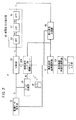
図1は、この発明の一実施の形態に係るスーパーセル閾値テンプレート(スーパーセル閾値配列)36が適用された製版システム10の基本的な構成を示している。
【0039】
図1例の製版システム10は、基本的には、画像入力部14と画像処理部16と2値網点画像データ作成部20と画像出力装置24とから構成される。この製版システム10は、画像入力部14により原稿画像12から読み取った画像を網点画像としてフイルムF上に形成するシステムである。
【0040】
この場合、画像入力部14において、光源からの光が照射され副走査方向に移送される原稿画像12からの反射光または透過光が、リニアイメージセンサ等の光電変換素子に導かれて電気的に主走査され、その光電変換素子を通じて電気信号である画像信号(画素信号)に変換される。変換された画像信号は、A/D変換器により例えば、値0、1、…、255をとる8ビットのデジタル画像データ(単に画像データともいう。)DAに変換される。
【0041】
なお、画像入力部14としては、このようなスキャナに限らず、DVD等の画像記録ディスク(画像記録媒体)、通信ネットワーク、デジタルスチルカメラ等、結果としてデジタル画像データを出力する媒体であればよい。
【0042】
画像入力部14から出力された画像データDAに対して、画像処理部16により、必要に応じて色補正処理、シャープネス処理の他、画像出力装置24の解像度に対応するための解像度変換処理等が行われて画像データGが作成される。
【0043】
この実施の形態において画像出力装置24の解像度、すなわち出力解像度は、例として、72走査線/mmであるものとする。なお、この走査線/mmの表現は、スクリーン線数と紛らわしいので、以下、出力解像度は、72dpm(dot/mm)で表すものとする。ここで、dotは、上記のように1画素を意味する。
【0044】
画像処理部16により所定の処理のなされた画像データGは、階調画像データ作成装置としての2値網点画像データ作成部20に供給される。なお、近年、2値網点画像データ作成部20に供給される画像データGとして、上記デジタルカメラ等、結果としてデジタル画像データを出力する媒体で画像処理がなされたものが直接供給される場合もある。
【0045】
2値網点画像データ作成部20は、ソフトウエアを用いてコンピュータにより実現することが可能であるが、ハードウエアにより実現することもできる。また、ソフトウエアとハードウエアとを混在させて実現することもできる。
【0046】
2値網点画像データ作成部20は、階調画像データ作成手段として機能する比較部32、アドレス計算部34、階調画像データ作成用閾値配列が複数記憶される記憶媒体としてのスーパーセル閾値テンプレート(閾値配列)36、および所望の閾値配列を選択する選択手段としての網属性入力部38から構成される。
【0047】
2値網点画像データ作成部20に供給された画像データGは、比較部32の比較入力に供給される。また、画像データGからスーパーセル閾値テンプレート36上のx軸とy軸のアドレスを表すアドレスAD=AD(x,y)がアドレス計算部34により計算される。
【0048】
スーパーセル閾値テンプレート36は、その指定されたアドレスADに格納されている閾値{この場合、値1、…255をとる8ビット(正確には、8ビットから1を引いた値であるが、便宜上、8ビットという。)の閾値データ}Tを読み出して比較部32の基準入力に供給する。
【0049】
スーパーセル閾値テンプレート36としては、複数のスーパーセル閾値テンプレート中、網属性入力部38により指定された網属性(スクリーン線数、網角度および網形状)に対応するものが使用される。なお、この実施の形態において、例として、スクリーン線数は175線であり、網角度は45°、網形状はスクエアに指定されているものとする。
【0050】
スーパーセルは、複数の網点セル(網点)から構成されている。一般に、網点生成技術分野においては、出力解像度により定まる画素グリッド上にスーパーセルを設定し、設定したスーパーセルを網点セルに分割し、分割した網点セル内の各画素に対応して閾値を割り当てて網点閾値を生成するようにされており、閾値が割り当てられたスーパーセルをスーパーセル閾値テンプレート(閾値配列)という。
【0051】
スーパーセルに関連して網点を生成する技術の参考文献としては、例えば、「書名:ポストスクリプト・スクリーニング、著者:ピーター・フィンク、発行元:株式会社エムディエヌコーポレーション、発行日:1994年8月11日、初版第1刷」を挙げることができる。
【0052】
複数の網点セルから構成されるスーパーセルを考えることで、スクリーン線数と網角度をより細かく変化させることが可能になり、指定されたスクリーン線数と網角度に、より近い値を選択することができるという有利さがある。
【0053】
画素グリッドとは、黒化単位である画素の集合体をいう。したがって、画素グリッドは、出力解像度で画素が縦横に整然と並んでいる状態をイメージすればよい。
【0054】
この実施の形態において、スーパーセル閾値テンプレート36としては、上述した特開平8−317212号公報(第1の技術)または特開平9−200518号公報(第2の技術)により公表されているものを使用している。
【0055】
比較部32では、画像データGと閾値データ(単に閾値ともいう。)Tについて、G≧T→1(オン、黒化)、G<T→0(オフ、白抜け、非黒化)の大小比較演算を行い、その比較演算結果の値1または値0をとる階調画像データとしての2値網点画像データ(2値データ、2値画像データ、網点画像データ、またはデジタル網点データともいう。)Hを作成する。
【0056】
作成された2値網点画像データH、すなわち階調画像データは、画像出力装置24を構成する露光記録部26に供給される。
【0057】
露光記録部26では、この露光記録部26内に配された感光材料M上を、2値網点画像データHに応じてオンオフするレーザビーム(記録ビーム)により露光走査記録して、感光材料M上に潜像としての網点画像を形成する。網点画像の形成された感光材料Mは、自動現像機28により現像処理されて、顕像化された網点画像が形成されたフイルムFが作成される。このフイルムFが原版とされて刷版が作成され、作成された刷版が図示していない印刷機に装着され、装着された刷版に対してインキが付けられる。
【0058】
刷版に付けられたインキが印画紙等のシート上に転移されることで、シート上に画像が形成された所望の印刷物を得ることができる。
【0059】
なお、この発明は、原版としてのフイルムFを出力する画像出力装置24ではなく、2値網点画像データHにより刷版PPを直接出力することの可能な画像出力装置であるCTP(computer to plate)出力機24aにも適用することができる。CTP出力機24a内では、感光材料Mがレーザビーム(記録ビーム)により走査記録されることで、直接、刷版PPが得られる。
【0060】
また、画像出力装置としては、いわゆるレーザ光を用いた走査露光装置に限らず、面露光方式やインクジェット方式でフイルム、刷版あるいは印刷物を描画する装置にも適用することができる。
【0061】
さらには、CTC(computer to cylinder)印刷機24bに2値網点画像データHを供給するように構成すれば、このCTC印刷機24bでは2値網点画像データHに基づき、シリンダに巻き付けられた感光材料Mが走査記録されて得られた刷版にインキが付けられ、刷版に付けられたインキがシートに転移されることで、シート上に画像形成された所望の印刷物PMを直接得ることができる。
【0062】
なお、図1例中の2値網点画像データ作成部20を構成するスーパーセル閾値テンプレート36の閾値配列はフロッピィディスク等の記憶媒体49に記憶されているものを用いている。
【0063】
この2値網点画像作成部20は、ハードウエアあるいはコンピュータ上でソフトウエアによって実行される場合がある。この場合、閾値配列は、ハードディスク等の記憶媒体に記憶されているものを用いる。
【0064】
以上が、この発明の一実施の形態の閾値配列が適用された製版システム10の基本的な構成についての説明である。
【0065】
次に、この発明の一実施の形態に係る階調画像作成用閾値配列決定方法を実施する階調画像作成用閾値配列作成装置について説明する。
【0066】
図2は、記憶手段であるRAM(ランダムアクセスメモリ)やハードディスク等の記憶媒体により構成され、それぞれ複数の1、2、…、255の閾値Tが割り当てられて作成されるスーパーセル閾値テンプレート(閾値配列)36の作成装置(階調画像作成用閾値配列作成装置)18の構成例を示している。なお、ここで階調画像とは、2値画像{黒化画素と非黒化(白ヌケ)画素とからなる画像}あるいは4値画像(例えば、4段階の濃度0、1、2、3で示される階調で構成される画像)等の多値画像を意味している。
【0067】
この図2例の階調画像作成用閾値配列作成装置18において、図1に示した製版システム10の構成要素と対応するものには、同一の符号を付けてその詳細な説明を省略する。
【0068】
階調画像作成用閾値配列作成装置18は、線数、角度、出力解像度、網形状等の入力パラメータを設定するパラメータ入力部37と、設定された入力パラメータに応じて実質線数角度を選択する実質線数角度選択部39と、選択された実質線数角度に応じて黒化候補画素を選択する黒化候補画素選択部41とを有している。
【0069】
また、階調画像作成用閾値配列作成装置18は、黒化候補画素選択部41により選択された黒化候補画素の選択に応じて、既に決定している閾値配列を発生させるように、閾値サイズ分で大きさが一定の画像データGを発生する画像データ発生部30と、発生された画像データGに基づいてアドレスADを計算して作成途中(作成途上)スーパーセル閾値テンプレート36Mに供給するアドレス計算部34と、最初は閾値Tが全てゼロ値とされ実質的に閾値Tが何も配置されていない状態から順次決定された閾値が記憶(保存)される作成途中スーパーセル閾値テンプレート36Mと、作成途中までの閾値(既決定の閾値)Tと画像データGとから値0または値1をとる2値網点画像データHを作成する比較部32を有している。
【0070】
さらに、階調画像作成用閾値配列作成装置18は、2値網点画像データHから低周波成分データ(低周波ノイズ成分、低周波ノイズデータ、低周波成分)Lを抽出する低周波成分抽出部45と、この低周波成分データLに基づき、前記黒化候補画素選択部41により選択された黒化候補画素の位置の低周波成分を算出するとともに、算出した低周波成分に基づき次の黒化画素位置を閾値の配置位置と決定する黒化画素決定部46を有している。
【0071】
ここで、低周波成分抽出部45は、周波数変換手段としての高速フーリエ変換器(FFT)40、低域通過フィルタ(LPF)42、周波数逆変換手段としての高速逆フーリエ変換器(IFFT)44とから構成される。なお、周波数変換手段としては、高速フーリエ変換器40にかぎらず、ウェブレット変換手段を使用することができ、ウェブレット変換手段を使用したときには、周波数逆変換手段としてウェブレット逆変換手段を使用する。
【0072】
また、低周波成分抽出部45は、周波数変換手段を持つことなく実空間上でのフィルタリング(コンボリューション演算)によって低周波成分を抽出することも可能である。コンボリューション演算のマスクサイズや画像データサイズにも依存するが、計算を実行するにあたっては、周波数変換手段を用いた方が、コンボリューション演算より演算時間を短くすることができる場合が多い。以下、周波数変換手段を用いた例について説明する。
【0073】
比較部32により作成された2値網点画像データHは、フーリエ変換手段である高速フーリエ変換器40に供給される。
【0074】
この2値網点画像データHは、位置空間(実空間)上の画像データである。ここで、位置空間上のデータとは、xy平面上で定義される座標上のデータであることをいう。この位置空間上の2値網点画像データHが、高速フーリエ変換器40により、周波数空間上の情報信号であるデータD1に変換され、遮断周波数が網点の基本周波数成分(スクリーン線数成分)に設定された低域通過フィルタ42に供給される。ここで、周波数空間上のデータとは、xy軸を周波数軸として、その周波数平面上で定義される座標上のデータであることをいう。
【0075】
低域通過フィルタ42は、周波数空間上のデータD1から網点の基本周波数成分(スクリーン線数成分)より低い周波数の低周波成分を含むデータD2を抽出して、高速逆フーリエ変換器44に供給する。
【0076】
高速逆フーリエ変換器44は、周波数空間上で抽出された低周波成分を含むデータD2を、位置空間上の画像データである低周波成分データLに変換して黒化画素決定部46に供給する。
【0077】
低周波成分データLに基づき黒化画素決定部46により決定された閾値配列は、作成途中スーパーセル閾値テンプレート36Mに記憶され、1〜255までの全ての閾値配列が決定されたとき、その作成途中スーパーセル閾値テンプレート36Mは、閾値配列が全て決定されているスーパーセル閾値テンプレートとされ、フロッピィディスク等の記憶媒体49に記憶され、この記憶媒体49から図1の製版システム10におけるスーパーセル閾値テンプレート36にコピーされ、製版システム10での使用に供される。
【0078】
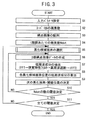
次に、階調画像作成用閾値配列作成装置18のより詳しい動作について、図3のフロー図を参照して説明する。
【0079】
まず、ステップS1では、パラメータ入力部37により入力パラメータを設定する。ここで、入力パラメータは、たとえば、スクリーン線数175線(LPI)=6.89線/mm、網角度45度、出力解像度72ドット/mm(画素/mm){1画素の大きさは13.9μm角}および網形状四角形(スクエア)とする。網形状としては、四角形以外に円形あるいはその他の幾何形状とすることができる。
【0080】
次いで、実質線数角度選択部39において、ステップS2、S3、S4では、それぞれ、閾値配列であるスーパーセル(スーパーセル閾値テンプレート36)の画素数が119画素×119画素に選択され、網点画像の配列(大きさ、個数、角度)が選択され、1階調あたりの画素数Ndotが選択される。ここで、1階調あたりの画素数Ndotは、次の(1)式により決定される。
【0081】

【0082】
なお、この実施の形態においては、理解の容易化のために作成途中スーパーセル閾値テンプレート36Mの閾値Tの配列がT=1からT=128まで決定されており、次に、55個(1つ以上)の次階調の閾値T=129の配置位置(同値1つ以上の閾値の配置位置)を決定する際の動作について説明する。
【0083】
この場合、ステップS5(便宜的にA過程という。)において、網の形状を損なわないように、次階調の同値複数の閾値の配置位置の候補位置を複数箇所選択する。ここで、候補位置は、次に黒化する候補の画素位置に対応するので、黒化候補画素という。
【0084】
この黒化候補画素の数をmとするとき、m=Ndot+α、たとえば、Ndot×2=110個に選択する。余裕度αを大きくすれば、閾値配列の自由度が増加するが、網の黒化形状が、この例ではスクエアからくずれていく。
【0085】
図4は、その黒化候補画素の選択手順例を示している。
【0086】
すなわち、ステップS5−1では、図5に模式的に示すように、たとえば、大きさを±1で規格化した各網点50の中心Oから未処理画素までの距離値、換言すれば、未だ閾値が配置されていない画素位置までの距離値を所望の形状であるスクエアに合致した次の(2)式の距離関数D(x,y)により求める。
【0087】
D(x,y)=1−(|x|+|y|) …(2)
この模式的に描いた図5において、中心Oを含む四角形51の内側までの閾値配列が決まっていた場合に、次に、四角形52の辺の付近の未処理画素までの距離値を距離関数D(x,y)により求めることになる。
【0088】
なお、距離関数D(x,y)は、黒化部分が円形で太る網点形状である場合には、次の(3)式で表されるものを用いればよい。
【0089】
D(x,y)=1−(x2+y2) …(3)
距離関数D(x,y)は、いわゆるスポット関数に対応する。
【0090】
次いで、ステップS5−2では、ステップS5−1で求めた距離値の中、最小値である最小値minD(x,y)を求める。
【0091】
ステップS5−3では、最小値minD(x,y)の配置位置が未処理画素であるかどうか、換言すれば、閾値が決定されていないかどうかを確認し、未処理画素でなかった場合には、ステップS5−2にもどり、未処理画素であった場合には、ステップS5−4において黒化候補画素とする。
【0092】
次いで、ステップS5−5においては、ステップS5−4までに決定した黒化候補画素数が黒化候補画素数m=Ndot+α(ここでは、m=110)に等しくなったかどうかを判定し、黒化候補画素数mに満たない場合には、黒化候補画素数mとなるまでステップS5−2〜ステップS5−5の処理を繰り返す。
【0093】
黒化候補画素数mが、黒化候補画素数m=Ndot+αに合致したとき、黒化候補画素選択部41は、黒化候補画素数mの各画素位置を黒化画素決定部46に転送通知する。
【0094】
次に、以下に説明するステップS6〜ステップS9の処理(便宜的にB過程という。)を繰り返し行うことにより複数の黒化候補画素(複数箇所の候補の閾値)の配列位置を決定する。
【0095】
すなわち、ステップS6の処理において、既に決まっている閾値配列が格納されている作成途中スーパーセル閾値テンプレート36Mにより階調画像である2値網点画像データHを比較部32により作成する。2値網点画像データHを作成する画像データGの値は、G=128とされる。すなわち、閾値T=129の配置位置を決定する場合に、既に決まっている閾値T=1〜128の閾値配列を表す2値網点画像データHを作成するときには、画像データ発生部30から画像データGの値として、一定値G=128がスーパーセル閾値サイズ分比較部32へ供給される。
【0096】
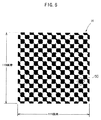
図6は、画像データGがG=128であるとき、作成途中スーパーセル閾値テンプレート36Mを用いて比較部32により作成された2値網点画像データHにより表される網点画像を模式的に示している。
【0097】
ここでは、網パーセントが50%の平網となっており、比較部32により得られた1個のスーパーセルに係る119画素×119画素分の2値網点画像データHによる網点画像(ビットパターンと考えることができる。)を示している。ここで、網点の基本周波数は、ほぼスクリーン線数に等しく、6.89(c/mm:サイクル/mm)と考えることができる。
【0098】
この図6から2値網点画像データHは、xy平面上で定義される座標上のデータ、すなわち位置空間上のデータ(z軸のデータと考えることができる。)が、値0(非黒化)または値1(黒化)をとるデータであることが理解される。
【0099】
図6において、例として描いた1個の網点50内には、約109(1452 /13.92 )個の画素が含まれる。なお、ステップS5の処理において、黒化候補画素選択部41において選択決定し、黒化画素決定部46に格納されている黒化候補画素数m(m=110個)の画素位置は、図6中、非黒化画素となっているいずれかの位置である。
【0100】
次に、ステップS7(第1の過程)では、2値網点画像データHの低周波成分を特別な処理により低周波成分抽出部45により抽出する。そのため、このステップS7では、まず、2値網点画像データHを、二次元のFFT40により高速フーリエ変換して、周波数空間上の情報信号であるデータD1に変換する。
【0101】
図7は、図6に示す位置空間上の2値網点画像データHに対応する、高速フーリエ変換後の周波数空間上のデータD1のFFTパワー図を示している。x軸とy軸は、周波数(c/mm)を示し、z軸はパワーを示している。
【0102】
この図7の周波数空間上のデータD1において、中心座標(x,y)=(0,0)における値が約0.5のパワーP1は、平網と仮定したときの網パーセントの50%に対応する基本成分であり、ノイズ(雑音)ではない。また、xy平面上、中心座標(x,y)=(0,0)から各45°方向上の座標(x,y)=(5,5)、(−5,5)、(−5,−5)、(5,−5)付近の座標位置に存在する値0.2程度のパワーP2〜P5も、網の基本周波数6.89(c/mm)に対応するパワーであり、ノイズではない。なお、例えば、パワーP2が存在する正確なx、y座標は、値5ではなく、6.89÷√2=4.87として計算することができる。
【0103】
モアレ縞は、網の周波数以下の周波数で発生する干渉縞であることを考えると、これら4点の座標(x,y)=(5,5)、(−5,5)、(−5,−5)、(5,−5)で囲まれた領域Q(図5のハッチング領域も参照)内に存在する周波数成分がモアレ縞と関係するノイズ成分(低周波成分)であることが理解される。
【0104】
図9は、領域Qを含む部分の図7のFFTパワー図の拡大図である。領域Q内に小さいながらも凹凸、すなわちパワー成分が存在することが分かる。
【0105】
次に、この領域Q以外の高周波成分を除去するために、領域Qに対応する遮断周波数を有する低域通過フィルタ42を作用させ、領域Q内の低周波成分を含むデータD2を抽出する。換言すれば、周波数空間上のデータD1から網点の基本周波数成分より低周波の低周波成分データD2を抽出する。なお、このとき、直流成分であるパワーP1も除去しておく。この直流成分の阻止をも考慮した場合に、低域通過フィルタ42は正確には帯域通過フィルタであるが、低周波ノイズ成分を含むデータを通過させるという意味で便宜上低域通過フィルタといっている。
【0106】
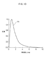
実際上、モアレ縞は人間が知覚するものであるから、FFT40により2値網点画像データHを高速フーリエ変換した後のデータD1中、領域Q以外の高周波成分を低域通過フィルタ42により除去する際に、図10に示す人間の視覚特性65により重み付けした後、低域通過フィルタ42をかけて低周波成分を抽出するようにしている。図10に示すように、人間の視覚特性65は、周波数0.8(c/mm)近傍で最大感度を有する特性である。
【0107】
次いで、IFFT44は、低域通過フィルタ42により抽出された低周波成分データS2を逆フーリエ変換して位置空間(実空間)上の低周波成分データLにする。
【0108】
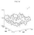
図11は、位置空間上における119画素×119画素領域上に鳥瞰図的に表した低周波成分データLを立体的に示している。すなわち、もとの画像上で低周波の濃度のうねりが3次元図形上の山や谷で抽出されていることが理解される。
【0109】
なお、この図11においては、図10に示す人間の視覚特性(人間の視覚周波数特性)65に基づく重み付けをかけていることから、IFFT44によるフーリエ逆変換後の低周波成分データLが人間の目に視認しやすいように、換言すれば、コンピュータによる大きさ(強さ)の判別がし易くなるように重み付けられた図形となっている。
【0110】
人間の視覚周波数特性のモデルについては、著者J.Sullivan, L.Ray,and R.Millerによる文献「Design of minimum visual modulation halftone patterns」IEEE Trans. Syst. Man Cybern., vol21,No.1,33-38(1991)にも詳しく述べられている。
【0111】
また、人間の視覚特性をかけて低周波成分を抽出する方式においても、上記説明した、周波数空間上のフィルタリング計算だけでなく、実空間上のコンボリューション演算でも抽出することができる。
【0112】
この低周波成分データLは、低周波成分抽出部45から黒化画素決定部46に供給される。
【0113】
そこで、ステップS8(第2の過程)において、黒化画素決定部46は、まず、この119画素×119画素の低周波成分データLと、図6に示した119画素×119画素の2値網点画像データHとを対比し、黒化候補画素数m=110の黒化候補画素位置に対応する各非黒化画素位置における低周波成分データLを図11から算出する。
【0114】
次いで、黒化画素決定部46は、ステップS9(第3の過程)において、ステップS8で算出した各非黒化画素位置における低周波成分データLの中、最も、値の小さい(低周波成分データのパワー値が弱い、換言すれば、低周波成分強度の最も弱い)黒化候補画素の位置を次に黒化すべき画素(黒化画素)に決定する。
【0115】
この場合、この次の黒化画素位置を次の閾値T=129の配列位置として、作成途中スーパーセル閾値テンプレート36M中の閾値位置のメモリアドレスに閾値T=129を格納する。なお、処理を早くするため、ステップS9における黒化画素の決定は1個ではなく小さい方から複数個を決めるようにしてもよい。
【0116】
次に、ステップS10において、黒化画素決定部46は、1階調あたりの画素数Ndot=55個分の閾値T=129の、作成途中スーパーセル閾値テンプレート36M中での配置位置が決定したかどうかを確認し、決定していない場合には、ステップS6からステップS9(第1の過程、第2の過程、第3の過程)までの処理を決定するまで繰り返す。なお、繰り返す際のステップS6の処理において、画像データ発生部30から出力される画像データGは、黒化画素決定部46からの黒化画素決定通知に基づき、次の階調の画像データG=129とされる。
【0117】
さらに、ステップS10における判断が成立したとき、すなわち、1階調あたりの画素数Ndotの全ての黒化画素に対応する閾値位置が決定したとき、ステップS11において、黒化画素決定部46は、閾値Tが最大値である閾値T=255までの全ての閾値配列が決定したかどうかを確認し、閾値配列が決定していない場合には、ステップS5からステップS10の処理を繰り返して閾値T=255までの全ての閾値配列を決定して処理を終了する。
【0118】
なお、全ての閾値配列が決定した作成途中スーパーセル閾値テンプレート36Mは、スーパーセル閾値テンプレート36とされ、その閾値テンプレート36のデータが記憶媒体49に記憶され、この記憶媒体49から図1に示した製版システム10中のスーパーセル閾値テンプレート36にコピーされる。
【0119】
以下、同様にして、ステップS1において新たなパラメータ(線数、角度、出力解像度、網形状等)を設定することにより、このパラメータに対応したスーパーセル閾値テンプレート36の閾値配列を略自動的に決定することができる。
【0120】
なお、上述した実施の形態においては、2値網点画像データHを対象としているが、この発明は2値網点画像データHに限らず、出力値が「0,1,2,3」の値をとる4値、8値等の多値網点画像データにも適用することができる。
【0121】
また、上述した実施の形態においては、図6に示した網点50による階調画像作成用の閾値配列の決定について説明しているが、この発明は、網点画像作成用の閾値テンプレートの作成に限らず、N×N画素を階調再現の1つの単位として考え、それに対応する階調画像作成用のN×N個の閾値テンプレート(ディザマトリクス)の閾値配列にも適用することができる。
【0122】
このディザマトリクスでは、画素の集合密度(周波数)を階調に応じて変化させるFM(周波数変調)スクリーンにも適用することができる。
【0123】
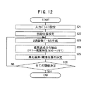
図12は、ディザマトリクスの閾値配列を決定するための手順を示すフロー図である。
【0124】
まず、ステップS21では、入力パラメータを設定する。ここで、入力パラメータは、出力解像度(画素/mm)、FMスクリーンにおける1画素の大きさ、ディザマトリクスの大きさ、例えばN画素×N画素(上述したように、設定すべき閾値Tは1からN2個となる。)である。
【0125】
次いで、ステップS22では、閾値T=1の初期位置をディザマトリクス中の適当な画素位置に決める。
【0126】
次いで、ステップS23では、閾値T=1のみが決定されたディザマトリクスと画素値が全て1であるN×N画素の画像データと比較して、2値画像データを比較部32により作成する。
【0127】
次いで、ステップS24では、ステップS7で説明したのと同様に、ステップS23で作成した2値画像データに対して低周波成分データの抽出処理を行う(第1の過程)。
【0128】
次いで、ステップS25では、次に黒化すべき画素の位置、換言すれば、次の閾値T=2を入れるべきディザマトリクス中の位置を決定する。このステップS5の処理では、低周波成分データの最も小さい(弱い)位置が次に黒化すべき画素位置であると決定すればよい(第2の過程)。
【0129】
次に、ステップS26では、N2個の全ての閾値配置位置が決定しているかどうかを判定し、全ての閾値の配置位置が決定するまで、この場合、次の閾値T=2の配列位置から最終閾値T=N2までステップS23〜ステップS25の処理を繰り返す。
【0130】
閾値を実際に使用する場合は、出力機に合わせた階調数に規格化して使用する。たとえば、出力機の階調数が256階調であれば、元の閾値をTとすると、新しい閾値は、閾値=T×(255/N2)として使用する。
【0131】
このように、1〜N2の閾値配列を決めた後に、必要階調数の閾値配列を求める方法は、前述の網点画像作成用閾値データを作成する際にも適用することができることはいうまでもない。
【0132】
このようにして、ディザマトリクスの閾値配列を決定することができる。閾値配列の決定したディザマトリクスは、記憶媒体49に格納することができる。
【0133】
なお、上述した図3のフロー図に基づく閾値配列の決定および図12のフロー図に基づく閾値配列の決定の際には、閾値T=1から網%では0%(小さい方)から昇順で順次黒化画素(閾値配列)を決定するようにしているが、この閾値配列の決定は、閾値Tの最大値から網%では100%(大きい方)から降順で順次決定するようにしてもよい。
【0134】
図2例の閾値配列作成装置18において、黒化画素決定部46および黒化候補画素選択部41を、それぞれ白化画素決定部および白化候補画素選択部に代替することで、降順に閾値の配置位置を決める方式に対応することが可能である。
【0135】
この場合、図3のフローチャート中、ステップS9(第3の過程)では、白化画素決定部(図4中の黒化画素決定部46に相当する。)が、ステップS8で算出した各非白化画素位置における低周波成分データLの中、最も、値の大きい(低周波成分データのパワー値が強い、換言すれば、低周波成分強度の最も強い)白化候補画素の位置を次に白化すべき画素(白化画素)に決定するようにすればよい。また、図12のフローチャート中、ステップS25の処理では、低周波成分データの最も大きい(強い)位置が次に白化すべき画素位置であると決定すればよい(第2の過程)。
【0136】
また、閾値の配置位置を決める場合に、ある特定の網%におけるドットの配置位置(2値パターン、ドットパターン、網点形状、白黒のパターン)のみが、特別の方法によって最適なドット配置位置として選ばれているような場合にも以下のように対応することができる。
【0137】
すなわち、配置位置が決定している閾値Tfixに対して階調の高い方の次階調の閾値Thの配置位置と階調の低い方の次階調の閾値Tlの配置位置を決定する際、階調の高い方の次階調の閾値Thの配置位置を決定する場合には、前記ドットパターン(閾値配列)の閾値Tを便宜的に全て0値として、昇順に閾値Th+1以降の閾値の配置位置を決定し、階調の低い方の次階調の閾値Tlの配置位置を決定する場合には、前記ドットパターン(閾値配列)の閾値Tを便宜的に全て最大値、たとえば、T=N2として、降順に閾値Tl−1以降の閾値の配置位置を決定すればよい。
【0138】
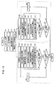
図13は、ある階調での閾値Tfixにおける配置位置(白黒のパターン、ドットパターン)が決定しているとき、階調の高い方の閾値Thと階調の低い方の閾値Tlの配置位置をそれぞれ決定する手順を示している。
【0139】
この図13に示すフローチャートにおけるステップS31〜S41の処理は、図3に示したフローチャートにおけるステップS1〜S11の処理内容と同様であり、また、図13に示すフローチャートにおけるステップS45〜S51の処理も同様にステップS5〜S11の処理内容と同様であるので、その詳細な説明を省略する。
【0140】
この図13に示すフローチャートにおいて、階調の高い方の次階調の閾値Thを決定する場合には、上述したように、ある閾値Tfixのドットパターンで黒化されている画素は、閾値Tに便宜的に0(常に黒化される画素)としてしまい、ステップS35における黒化候補画素として選択されないようにして、初期値としての次階調の閾値Th=Tfix+1以上の閾値Tの配置位置を順次決定する。なお、ステップS34Aは、初期値の閾値Th=Tfix+1の設定を示し、ステップS42は、閾値Tの高い方の次階調の閾値Th(Th=Th+1)への閾値の更新処理を示している。
【0141】
同様に、階調の低い方の次階調の閾値Tlの配置位置を決定する場合にも、上述したように、ある閾値Tfixのドットパターンで白化されている画素は、閾値Tを便宜的に、たとえば255(常に白化される画素)としてしまい、白化候補画素として選択されないようにしてTfix−1以下の閾値Tの配置位置を順次決定する。なお、ステップS34Bは、初期値の閾値Tl=Tfix−1の設定そ示し、ステップS52は、閾値Tの低い方の次階調の閾値Tl(Tl=Tl−1)への閾値の更新処理を示している。
【0142】
ここで、ステップS45においては、ステップS5と同様に、網の形状を損なわないように、低い方の次階調の同値複数の閾値Tlの配置位置の候補位置を複数箇所選択する。ここで、候補位置は、次に白化する候補の画素位置に対応するので、白化候補画素という。
【0143】
また、次階調の閾値ThとTlの配置位置を決定する際、1階調ずつ同時に決定してもよく、高い方の閾値Thの配置位置を全て決めた後、低い方の閾値Tlの配置位置を決めるように、独立に決定してもよい。
【0144】
この場合、複数の異なる網%に対応する複数の異なる階調での閾値のそれぞれから昇順および降順に閾値の配置位置を決定するように構成を変更することも可能である。
【0145】
図14は、2箇所の異なるある階調までの閾値Tfix1、Tfix2(Tfix1<Tfix2)の配置位置(白黒のパターン、ドットパターン)が決定しているとき、初期値の閾値をそれぞれステップS64A、S64Bに示すように、閾値Th=Tfix1+1、Tl=Tfix2−1とし、閾値Tfix1と閾値Tfix2の間の閾値の配置位置を決定する手順を示している。
【0146】
この図14に示すフローチャートにおけるステップS61〜S69、S80、S81の処理は、図3に示したフローチャートにおけるステップS1〜S11の処理内容と同様であり、また、図14に示すフローチャートにおけるステップS75〜S81の処理も同様にステップS5〜S11の処理と同様であるので、その詳細な説明を省略する。
【0147】
この図14に示すフローチャートにおいては、図13例のように高い方と低い方の次階調の閾値ThとTlの配置位置を独立に計算するのではなく、平均の値(Tfix1+Tfix2)/2で閾値の配置位置が一致するように、高い方の次階調の閾値Thと低い方の次階調の閾値Tlの増加(Th=Th+1)と減少(Tl=Tl−1)を同じタイミングで行い、高い方と低い方の次階調の閾値Th、Tl側で1画素ずつ閾値の配置位置を決定する。
【0148】
なお、ステップS65、S75の候補画素の選択の際には、高い方と低い方の次階調の閾値Th、Tl側のどちらにも閾値の配置位置が決まっていない画素の中から候補画素を選択する。この図14例では、高い方の次階調の閾値Thを低い方の次階調の閾値Tlより先に処理しているが、低い方の次階調の閾値Tlの配置位置を先に処理してもよい。
【0149】
このようにすれば、閾値Tfix1、Tfix2に対応する特定の網%での好ましいドットパターンを保持したまま、閾値Tfix1、Tfix2の間もモアレの発生を抑制した閾値配置を決定することができる。
【0150】
また、この方式で決定した閾値配列として、閾値Tfix1=0%(全て白)、閾値Tfix2=100%(全て黒)と設定し、網%で0%(=Tfix1)〜50%は昇順に、網%で100%(=Tfix2)〜50%は降順に閾値配置を決定する方式も当然に含まれる。
【0151】
ある網%、たとえば、30%、50%、70%で2値パターンを決定し、その前後に閾値配列を決定する場合について、具体的に説明する。
【0152】
この場合、0〜30%の閾値は、30%のドットパターンを基に、図3の手順に対応して降順に0%までの閾値の配置位置を決定する。30〜50%の閾値は、図14の手順に従い、30〜40%までの閾値は、30%のドットパターンを基に30%から昇順に配置位置を決定し、40〜50%までの閾値は、50%のドットパターンを基に50%から降順に配置位置を決定する。
【0153】
さらに、50〜70%までの閾値範囲では、50〜60%の閾値の配置位置を50%のドットパターンを基に50%から昇順に決定し、60〜70%の閾値の配置位置は70%のドットパターンを基に70%から降順に閾値の配置位置を決定する。
【0154】
さらに、70〜100%の閾値は、70%の閾値を基に、図3の手順により昇順で100%までの配置位置を決定する。
【0155】
図15は、網点ではなく、ディザマトリクスの閾値配列において、ある閾値Tfixにおける配置位置(白黒のパターン、ドットパターン)が決定しているとき、階調の高い方の閾値Thと階調の低い方の閾値Tlの配置位置を決定する手順を示している。
【0156】
この図15に示すフローチャートにおけるステップS121、S123〜S126の処理は、図12に示したフローチャートにおけるステップS21、S23〜S26の処理内容と同様であり、また、図15に示すフローチャートにおけるステップS223〜S226の処理も同様にステップS23〜S26の処理内容と同様であるので、その詳細な説明を省略する。
【0157】
ここで、ステップS122Aの処理では、初期値として閾値Th=Tfix+1が設定され、ステップS127で、高い方の次階調の閾値Th=Th+1に更新される。
【0158】
また、ステップS122Bの処理では初期値として閾値Tfix−1が設定され、ステップS227で、低い方の次階調の閾値Tl=Tl−1に更新される。
【0159】
このようにして、ある階調の閾値T=Tfixでのドットパターンの決定しているディザマトリクスの全体の閾値配列を決定することができる。この閾値配列は、予め決められたTfixでのドットパターンを保持しつつ、その近傍でモアレの発生を抑えることの可能な閾値配列となる。閾値配列の決定したディザマトリクスは、記憶媒体49に格納することができる。
【0160】
図16は、網点ではなく、ディザマトリクスの閾値配列において、複数の異なるある階調までの閾値Tfix1、Tfix2(Tfix1<Tfix2)における配置位置(白黒のパターン、ドットパターン)が決定しているとき、閾値Tfix1と閾値Tfix2との間の閾値Tの配置位置を決定する手順を示している。
【0161】
この図16に示すフローチャートにおけるステップS321、S323〜S325の処理は、図12に示したフローチャートにおけるステップS21、S23〜S25の処理内容と同様であり、また、図16に示すフローチャートにおけるステップS423〜S426の処理も同様にステップS23〜S26の処理内容と同様であるので、その詳細な説明を省略する。
【0162】
ここで、ステップS322A、S322Bの処理では、初期値としてそれぞれ閾値Th=Tfix1+1、Th=Tfix2−1が設定され、ステップS427で、高い方の次階調の閾値Th=Th+1と低い方の次階調Tl=Tl−1に更新される。
【0163】
ここで、初期値としての閾値Th=Tfix1+1と更新された閾値Th=Th+1は、ステップS323〜S325の高い方の閾値Thの配置位置の決定処理に使用され、初期値としての閾値Tl=Tfix2−1と更新された閾値Tl=Tl−1は、ステップS423〜S425の低い方の閾値Tlの配置位置の決定処理に使用される。
【0164】
なお、低い方の閾値Tfix1以下の閾値の配置位置については、図15に示したステップS122B、S223〜S227の手順を使用して決定することができ、高い方の閾値Tfix2以上の閾値の配置位置については、図15に示したステップS122A、S123〜S127の手順を使用して決定することができる。
【0165】
このようにして、複数の異なるある階調の閾値T=Tfix1、Tfix2でのドットパターンの決定しているディザマトリクスの全体の閾値配列を決定することができる。このようにすれば、閾値Tfix1、Tfix2に対応する特定の網%での好ましいドットパターンを保持したまま、閾値Tfix1、Tfix2の間もモアレの発生を抑制した閾値配置を決定することができる。閾値配列の決定したディザマトリクスは、記憶媒体49に格納することができる。
【0166】
この場合においても、この方式で決定した閾値配列として、閾値Tfix1=0%(全て白)、閾値Tfix2=100%(全て黒)と設定し、網%で0%(=Tfix1)〜50%は昇順に、網%で100%(=Tfix2)〜50%は降順に閾値配置を決定する方式も当然に含まれる。
【0167】
なお、この発明は、上述した実施の形態に限らず、この発明の要旨を逸脱することなく、種々の構成を採りうることはもちろんである。
【0168】
【発明の効果】
以上説明したように、この発明によれば、周期的な模様やモアレの発生のきわめて少ない閾値配列を決定することができる。
【0169】
また、この発明によれば、出力される階調画像データにより形成される階調画像上でモアレ等の低周波成分の発生を抑制することができる。
【図面の簡単な説明】
【図1】この発明の一実施の形態に係るスーパーセル閾値テンプレートが適用された製版システムの構成を示すブロック図である。
【図2】閾値作成装置の構成を示すブロック図である。
【図3】閾値配列の決定手順を示すフロー図である。
【図4】図3例の閾値配列決定手順中、黒化候補画素の選択処理の詳細な処理手順を示すフロー図である。
【図5】距離関数の説明に供される線図である。
【図6】閾値配列決定前の2値網点画像データにより表される位置空間上の画像を示す線図である。
【図7】閾値配列決定前の2値網点画像データを高速フーリエ変換したときのFFTパワーを示す線図である。
【図8】抽出しようとする低周波成分の領域の説明に供される線図である。
【図9】抽出しようとする低周波成分の領域を拡大したFFTパワーを示す線図である。
【図10】人間の視覚特性の説明に供される特性図である。
【図11】抽出した低周波成分を逆フーリエ変換したときの位置空間上での低周波成分の形状を示す線図である。
【図12】ディザマトリクスの閾値配列の決定手順説明を示すフロー図である。
【図13】ある階調での閾値のドットパターンが決定している場合の閾値配列の決定手順を示すフロー図である。
【図14】2箇所の異なる階調での閾値のドットパターンが決定している場合の閾値配列の決定手順を示すフロー図である。
【図15】ある階調での閾値でのドットパターンが決定している場合のディザマトリクスの閾値配列の決定手順を示すフロー図である。
【図16】2箇所の異なる階調での閾値のドットパターンが決定している場合のディザマトリクスの閾値配列の決定手順を示すフロー図である。
【符号の説明】
10…製版システム 12…原稿画像
14…画像入力部 16…画像処理部
18…階調画像作成用閾値配列作成装置
20…2値網点画像データ作成部(階調画像データ作成装置)
32…比較部 34…アドレス計算部
36…スーパセル閾値テンプレート(網点閾値データ)
36M…作成途中スーパーセル閾値テンプレート
37…パラメータ入力部 38…網属性入力部
40…FFT 41…黒化候補画素選択部
42…LPF 44…IFFT
46…黒化画素決定部 49…記憶媒体
50…網点 AD…アドレス
DA、G…画像データ F…フイルム
H…修正後の網点画像データ L…低周波成分データ
M…感光材料 PP…刷版
PM…印刷物 S1…周波数空間上のデータ
S2…低周波成分データ T…閾値データ(閾値)[0001]
BACKGROUND OF THE INVENTION
The present invention relates to a gradation image creation threshold array determination method and a gradation image data creation apparatus that are suitable for printing field devices such as a color scanner, an image setter, a CTP device, a CTC device, and a DDCP.
[0002]
[Prior art]
In a halftone image output device such as an image setter that forms a halftone image consisting of binary values (for example, a blackened portion and a non-blackened portion by turning on / off a laser beam) on photographic paper or film, the output resolution and screen It has been pointed out that moire fringes caused by interference with the number of lines may occur on the output image (see Japanese Patent Application Laid-Open No. 8-317212).
[0003]
Here, the output resolution is the resolution of the image output apparatus, and is defined by dpi (dot per inch), pixels / inch (agreeing with dpi), pixels / mm, or the like. The number of screen lines is defined by lines / inch (convertible to lines / mm), which is the number of lines of halftone dots (also referred to as halftone cells) included per unit length (1 inch), and lpi (Line per inch), number of lines, screen frequency or halftone frequency.
[0004]
Moire fringes generated by interference between the output resolution and the number of screen lines are periodic patterns of halftone dots, that is, periodic interference fringes generated between the halftone dot pitch and the scanning line pitch. This moire fringe becomes a low-frequency noise component and degrades the image quality.
[0005]
The inventor of this application has proposed a technique for reducing this low-frequency noise component, as disclosed in Japanese Patent Application Laid-Open No. 8-317212 (referred to as the first technique), Japanese Patent Application Laid-Open No. 9-200518 (referred to as the second technique), and the like. This is proposed in Japanese Patent Application Laid-Open No. 11-112814 (referred to as the third technique).
[0006]
In the first technique, a threshold arrangement position in a threshold array (also referred to as a threshold template or a threshold matrix) used when generating binary halftone dot image data is devised, and blackening is performed in the threshold array. This is intended to reduce the occurrence of low-frequency noise components by aligning the number of pixels (non-blackened) as much as possible.
[0007]
In the second technique, random numbers are added when the thresholds are arranged in the threshold array in the first technique to further reduce the generation of low-frequency noise components.
[0008]
Furthermore, the third technique compares the median value within a predetermined threshold correction range with the threshold value before correction among the existing threshold values before correction in the threshold value array, and after converting it to halftone image data, The data is converted into data on the frequency space, and data including a low frequency noise component lower than the fundamental frequency component of the halftone dot is extracted from the data, and converted into image data on the real space. The data in the real space after the conversion and the threshold value before the correction are observed within the predetermined threshold correction range, and the pair of threshold values to be replaced are set under a certain condition (basically in the real space). This is a technique for obtaining a corrected threshold value array by selecting and replacing the threshold value pair at a position where a pixel having the maximum value and the minimum value of image data is generated.
[0009]
According to the third technique, the corrected threshold array itself is an array in which low-frequency noise components are unlikely to occur.
[0010]
In the first and second techniques, a certain low frequency component generation reduction degree is achieved. However, for example, when a higher quality image is handled, further improvement of the low frequency component generation reduction degree is required. Yes.
[0011]
In the third technique, the generation of low-frequency noise components can be considerably reduced. However, since this technique is a technique for correcting a threshold value that has already been created, the degree of freedom of correction is limited, and the effect of noise reduction. There may be cases where this is not fully achieved.
[0012]
[Problems to be solved by the invention]
The present invention has been made in connection with such problems and techniques, and does not modify the existing threshold arrangement, but is unlikely to generate low-frequency noise components. In other words, a gradation image is output. It is an object of the present invention to provide a threshold value array determining method for creating a gradation image that makes it possible to create a threshold value array from which moire is unlikely to occur from the beginning.
[0013]
It is another object of the present invention to provide a gradation image data creation device that can suppress the generation of low frequency components such as moire on a gradation image formed by output gradation image data. And
[0014]
[Means for Solving the Problems]
The gradation image creating threshold value array determining method according to the present invention has one or more threshold values having the same value of the next gradation when the threshold arrangement positions from the smaller threshold value to a certain gradation value are determined in the threshold value array. When determining the arrangement position of the next gradation, the process A for determining one or more candidate positions of one or more threshold values having the same value of the next gradation, and determining the arrangement position of the threshold value of the next gradation among the candidate positions A first step of extracting a low frequency component of image data obtained based on a threshold arrangement in which the arrangement positions of the thresholds up to a certain gradation are determined; A second step of determining the low-frequency component intensity at each candidate position of the one or more locations, and a third process of determining a candidate position having the weakest low-frequency component intensity as an arrangement position of the threshold value of the next tone And the third process from the first process to the third process. All positions equivalence one or more threshold gradation is characterized repeated to perform up to determine (the invention according to claim 1).
[0015]
The alphabets “A” and “B” in the “A process” and “B process” are merely used for the convenience of understanding the present invention. The same applies to the “C process” used in the following description.
[0016]
Claims5, 6, 7, 8The described invention will be better understood, for example, by reference to FIGS. 13-16, respectively.
[0017]
According to the present invention, the third process of determining the candidate position having the weakest low frequency component intensity as the arrangement position of the threshold value of the next tone is a processing process in the real space, and is accurately and accurately viewed. The location of the next threshold can be determined.
[0018]
In this way, the threshold value array used for creating the gradation image becomes a threshold value array that suppresses unnecessary low-frequency components when the gradation image is created.
[0019]
In the first aspect of the present invention, the threshold values are determined in ascending order from the smaller side (the smallest value in the case of the smallest), but the third process is a candidate position where the obtained low frequency component intensity is strongest. Can be determined in descending order from the side with the larger threshold value (the maximum value when the threshold value is the largest) by setting the threshold value for the next gradation as the arrangement position (the invention according to claim 2).
[0020]
Further, the threshold image determination method for gradation image creation according to the present invention is arranged such that when the threshold arrangement position from the smaller threshold value to a certain gradation is determined during the threshold value arrangement, the threshold value arrangement of the next gradation is determined. When determining the position, after extracting the low frequency component of the image data obtained based on the threshold arrangement in which the threshold arrangement position up to a certain gradation is determined, the position where the extracted low frequency component intensity is the weakest The arrangement position of the threshold value of the next gradation is determined (the invention according to claim 3).
[0021]
According to the present invention, the second process of determining the position where the low frequency component intensity is the weakest as the arrangement position of the threshold value of the next gradation is a processing process in the real space, and the next threshold value is accurately and accurately viewed. Can be determined.
[0022]
In this way, the threshold value array used for creating the gradation image becomes a threshold value array that suppresses unnecessary low-frequency components when the gradation image is created.
[0023]
In the third aspect of the present invention, the threshold values are determined in ascending order from the smaller side (in the case of the smallest, the minimum value), but the third process is the candidate position where the obtained low frequency component intensity is strongest. Can be determined in descending order from the larger threshold value side (the maximum value in the case of the largest threshold value).
[0027]
Further, according to the threshold value arrangement determination method for gradation image creation of the present invention, when the arrangement of the threshold values in a certain gradation is determined, the higher gradation is in ascending order and the lower gradation is in descending order. Threshold arrangements for all gradations can be determined (claims)5, 7Described invention).
[0028]
Then, when threshold arrangement positions at a plurality of different gradations are determined in the threshold array, the threshold arrangement positions between the plurality of different gradations are ascending in ascending order from the lower threshold value. All can be determined in descending order from the threshold with the higher gradation.6, 8Described invention).
[0029]
In the first to eighth aspects of the invention, by extracting the low frequency component by weighting according to human visual characteristics, it becomes possible to extract the low frequency component in a form closer to human perception (claim 9). ).
[0030]
Claim1-9By using the threshold array in the described invention as a dither matrix, generation of unnecessary low-frequency components on the gradation image created using the dither matrix is suppressed (the invention according to claim 12).
[0032]
For the convenience of understanding, the claims5, 6, 7, 8The correspondence between each process in the description and the steps (processes) in FIGS. 13 to 16 in the embodiment will be described.
[0033]
Claim5→ FIG. 13: Aa process → Step S35, Ba1 process → Step S37, Ba2 process → Step S38, Ba3 process → Step S39, Ca process → Step S42, Ab process →
[0034]
Claim6→ FIG. 14: Ac process → Step S65, Bc1 process → Step S67, Bc2 process → Step 68, Bc3 process → Step S69, Ad process → Step S75, Bd1 process → Step S77, Bd2 process → Step S78, Bd3 process →
[0035]
Claim7→ FIG. 15: first process → step S124, second process → step S125, third process → step S127, fourth process → step S224, fifth process → step S225, sixth process → step S227.
[0036]
Claim8→ FIG. 16: first process → step S324, second process → step S325, third process → step S424, fourth process → step S425, fifth process → step S427.
[0037]
DETAILED DESCRIPTION OF THE INVENTION
Hereinafter, an embodiment of the present invention will be described with reference to the drawings. First, in order to facilitate understanding of the present invention, the basics of a plate making system to which a threshold array according to an embodiment of the present invention is applied. A typical configuration will be briefly described.
[0038]
FIG. 1 shows a basic configuration of a
[0039]
The
[0040]
In this case, in the
[0041]
The
[0042]
For the image data DA output from the
[0043]
In this embodiment, the resolution of the
[0044]
The image data G that has been subjected to predetermined processing by the
[0045]
The binary halftone dot image data creation unit 20 can be realized by a computer using software, but can also be realized by hardware. It can also be realized by mixing software and hardware.
[0046]
The binary halftone dot image data creation unit 20 includes a
[0047]
The image data G supplied to the binary halftone dot image data creation unit 20 is supplied to the comparison input of the
[0048]
The supercell
[0049]
As the
[0050]
The supercell is composed of a plurality of halftone cells (halftone dots). In general, in the halftone generation technology field, a supercell is set on a pixel grid determined by the output resolution, the set supercell is divided into halftone cells, and a threshold value corresponding to each pixel in the divided halftone cell is set. Is assigned to generate a halftone threshold, and the supercell to which the threshold is assigned is referred to as a supercell threshold template (threshold array).
[0051]
References for techniques for generating halftone dots in relation to supercells include, for example, “Book Title: Postscript Screening, Author: Peter Fink, Publisher: MD Corporation, Publication Date: August 1994” 11th, first edition first print ".
[0052]
By considering a supercell composed of a plurality of halftone cells, it is possible to change the screen line number and the halftone angle more finely, and select a value closer to the specified screen line number and halftone angle. There is an advantage that it can be.
[0053]
A pixel grid refers to a collection of pixels that are blackening units. Therefore, the pixel grid may image a state in which the pixels are arranged in the vertical and horizontal order at the output resolution.
[0054]
In this embodiment, as the
[0055]
In the
[0056]
The generated binary halftone image data H, that is, gradation image data, is supplied to an
[0057]
The
[0058]
By transferring the ink applied to the printing plate onto a sheet such as photographic paper, a desired printed matter having an image formed on the sheet can be obtained.
[0059]
The present invention is not an
[0060]
Further, the image output apparatus is not limited to a scanning exposure apparatus using a so-called laser beam, and can be applied to an apparatus that draws a film, a printing plate, or a printed matter by a surface exposure method or an inkjet method.
[0061]
Further, if the binary dot image data H is supplied to a CTC (computer to cylinder)
[0062]
The threshold array of the
[0063]
This binary halftone dot image creation unit 20 may be executed by software on hardware or a computer. In this case, the threshold value array used is stored in a storage medium such as a hard disk.
[0064]
The above is the description of the basic configuration of the
[0065]
Next, a gradation image creating threshold value array creating apparatus for carrying out a gradation image creating threshold value array determining method according to an embodiment of the present invention will be described.
[0066]
FIG. 2 shows a supercell threshold value template (threshold value) which is configured by a storage medium such as a RAM (Random Access Memory) or a hard disk as a storage means, and is created by assigning a plurality of
[0067]
In the gradation image creating threshold value
[0068]
The gradation image creating threshold
[0069]
Further, the threshold
[0070]
Further, the gradation image creating threshold
[0071]
Here, the low frequency
[0072]
Moreover, the low frequency
[0073]
The binary halftone image data H created by the
[0074]
This binary halftone dot image data H is image data in a position space (real space). Here, the data on the position space means data on coordinates defined on the xy plane. The binary halftone dot image data H on the position space is converted into data D1 which is an information signal on the frequency space by the
[0075]
The low-
[0076]
The fast
[0077]
The threshold value array determined by the blackened
[0078]
Next, a more detailed operation of the gradation image creating threshold value
[0079]
First, in step S <b> 1, input parameters are set by the
[0080]
Next, in steps S2, S3, and S4, the number of pixels of the supercell (supercell threshold template 36) that is the threshold array is selected to be 119 pixels × 119 pixels in the substantial line number angle selection unit 39, and the halftone image Is selected, and the number of pixels Ndot per gradation is selected. Here, the number of pixels Ndot per gradation is determined by the following equation (1).
[0081]
[0082]
In this embodiment, for easy understanding, the threshold T array of the supercell threshold template 36M in the process of creation is determined from T = 1 to T = 128, and then 55 (one The operation at the time of determining the arrangement position of the next gradation threshold T = 129 (the arrangement position of one or more thresholds with the same value) will be described.
[0083]
In this case, in step S5 (referred to as “A process” for convenience), a plurality of candidate positions of the same threshold values for the next gradation are selected so as not to impair the shape of the mesh. Here, since the candidate position corresponds to the pixel position of the candidate to be blackened next, it is referred to as a blackened candidate pixel.
[0084]
When the number of blackening candidate pixels is m, m = Ndot + α, for example, Ndot × 2 = 110 is selected. Increasing the margin α increases the degree of freedom of the threshold arrangement, but the blackened shape of the mesh deviates from the square in this example.
[0085]
FIG. 4 shows an example of the procedure for selecting the blackening candidate pixels.
[0086]
That is, in step S5-1, as schematically shown in FIG. 5, for example, the distance value from the center O of each halftone dot 50 normalized by ± 1 to the unprocessed pixel, in other words, still The distance value to the pixel position where the threshold value is not arranged is obtained by the distance function D (x, y) of the following equation (2) that matches the square that is the desired shape.
[0087]
D (x, y) = 1−(| x | + | y |) ... (2)
In this schematically drawn FIG. 5, when the threshold arrangement to the inside of the square 51 including the center O is determined, the distance value to the unprocessed pixel near the side of the square 52 is then expressed as a distance function D. (X, y).
[0088]
Note that the distance function D (x, y) may be expressed by the following equation (3) when the blackened portion has a circular and thick halftone dot shape.
[0089]
D (x, y) = 1- (x2+ Y2(3)
The distance function D (x, y) corresponds to a so-called spot function.
[0090]
Next, in step S5-2, the minimum value minD (x, y), which is the minimum value, is obtained from the distance values obtained in step S5-1.
[0091]
In step S5-3, it is confirmed whether or not the arrangement position of the minimum value minD (x, y) is an unprocessed pixel, in other words, whether or not a threshold value has been determined. Returns to step S5-2, and if it is an unprocessed pixel, it is set as a blackening candidate pixel in step S5-4.
[0092]
Next, in step S5-5, it is determined whether or not the number of blackening candidate pixels determined up to step S5-4 is equal to the number of blackening candidate pixels m = Ndot + α (here m = 110). When the number of candidate pixels is less than m, the processes of Steps S5-2 to S5-5 are repeated until the number of blackening candidate pixels becomes m.
[0093]
When the blackening candidate pixel number m matches the blackening candidate pixel number m = Ndot + α, the blackening candidate
[0094]
Next, the arrangement positions of a plurality of blackening candidate pixels (threshold thresholds at a plurality of locations) are determined by repeatedly performing the processing of step S6 to step S9 described below (referred to as B process for convenience).
[0095]
That is, in the process of step S6, the
[0096]
FIG. 6 schematically shows a halftone dot image represented by the binary halftone dot image data H created by the
[0097]
Here, a halftone dot is a flat halftone dot with a dot percentage of 50%, and a halftone dot image (bits) based on binary halftone dot image data H of 119 pixels × 119 pixels related to one supercell obtained by the
[0098]
From FIG. 6, binary halftone dot image data H is data on coordinates defined on the xy plane, that is, data on the position space (which can be considered as z-axis data) has a value of 0 (non-black). It is understood that the data takes the value 1 (blackening).
[0099]
In FIG. 6, one
[0100]
Next, in step S7 (first process), the low frequency component of the binary halftone image data H is extracted by the low frequency
[0101]
FIG. 7 shows an FFT power diagram of data D1 on the frequency space after the fast Fourier transform, corresponding to the binary halftone image data H on the position space shown in FIG. The x-axis and y-axis indicate frequency (c / mm), and the z-axis indicates power.
[0102]
In the data D1 on the frequency space in FIG. 7, the power P1 having a value of about 0.5 at the center coordinate (x, y) = (0, 0) is 50% of the net percentage when the flat net is assumed. It is a corresponding basic component, not noise. On the xy plane, coordinates (x, y) = (5, 5), (−5, 5), (−5, 5) on the 45 ° direction from the center coordinate (x, y) = (0, 0). −5), powers P2 to P5 having a value of about 0.2 existing at coordinate positions near (5, −5) are also powers corresponding to the fundamental frequency 6.89 (c / mm) of the network, Absent. For example, the exact x and y coordinates where the power P2 exists can be calculated as 6.89 ÷ √2 = 4.87 instead of the
[0103]
Considering that the moire fringes are interference fringes generated at a frequency lower than that of the network, the coordinates (x, y) = (5, 5), (−5, 5), (−5, 5) of these four points are used. -5), it is understood that the frequency component existing in the region Q (see also the hatched region in FIG. 5) surrounded by (5, -5) is a noise component (low frequency component) related to moire fringes. The
[0104]
FIG. 9 is an enlarged view of the FFT power diagram of FIG. It can be seen that unevenness, that is, a power component exists in the region Q although it is small.
[0105]
Next, in order to remove high-frequency components other than the region Q, the low-
[0106]
In practice, since moire fringes are perceived by humans, high-frequency components other than the region Q are removed by the low-
[0107]
Next, the
[0108]
FIG. 11 three-dimensionally shows the low-frequency component data L represented in a bird's eye view on a 119 pixel × 119 pixel region in the position space. That is, it is understood that low-frequency density undulations are extracted from the original image at peaks and valleys on the three-dimensional figure.
[0109]
In FIG. 11, since weighting is applied based on the human visual characteristic (human visual frequency characteristic) 65 shown in FIG. 10, the low-frequency component data L after inverse Fourier transform by
[0110]
For a model of human visual frequency characteristics, see the article "Design of minimum visual modulation halftone patterns" by the author J. Sullivan, L. Ray, and R. Miller, IEEE Trans. Syst. Man Cybern., Vo.l21, No. 1, 33-38 (1991).
[0111]
Further, even in a method of extracting low-frequency components by applying human visual characteristics, extraction can be performed not only by the above-described filtering calculation in the frequency space but also by a convolution calculation in the real space.
[0112]
The low frequency component data L is supplied from the low frequency
[0113]
Therefore, in step S8 (second process), the blackened
[0114]
Next, in step S9 (third process), the blackened
[0115]
In this case, the next blackened pixel position is set as the array position of the next threshold T = 129, and the threshold T = 129 is stored in the memory address at the threshold position in the supercell threshold template 36M in the process of creation. In order to speed up the processing, the determination of the blackened pixels in step S9 may be determined from a smaller one instead of one.
[0116]
Next, in step S10, has the blackened
[0117]
Further, when the determination in step S10 is established, that is, when the threshold positions corresponding to all the blackened pixels of the number of pixels Ndot per gradation are determined, in step S11, the blackened
[0118]
Note that the supercell threshold template 36M in the process of creation in which all threshold arrays are determined is the
[0119]
Thereafter, in the same manner, by setting new parameters (number of lines, angle, output resolution, mesh shape, etc.) in step S1, the threshold array of the
[0120]
In the above-described embodiment, the binary halftone image data H is targeted. However, the present invention is not limited to the binary halftone image data H, and the output value is “0, 1, 2, 3”. The present invention can also be applied to multi-value halftone image data such as 4-value or 8-value.
[0121]
Further, in the above-described embodiment, the determination of the threshold arrangement for creating a gradation image by the
[0122]
This dither matrix can also be applied to an FM (frequency modulation) screen that changes the collective density (frequency) of pixels in accordance with gradation.
[0123]
FIG. 12 is a flowchart showing a procedure for determining the threshold arrangement of the dither matrix.
[0124]
First, in step S21, input parameters are set. Here, the input parameters are the output resolution (pixels / mm), the size of one pixel on the FM screen, the size of the dither matrix, for example, N pixels × N pixels (as described above, the threshold T to be set is 1). N2It becomes a piece. ).
[0125]
Next, in step S22, the initial position of the threshold T = 1 is determined as an appropriate pixel position in the dither matrix.
[0126]
Next, in step S23, the
[0127]
Next, in step S24, as described in step S7, low-frequency component data extraction processing is performed on the binary image data created in step S23 (first process).
[0128]
Next, in step S25, the position of the pixel to be blacked out next, in other words, the position in the dither matrix where the next threshold value T = 2 is to be entered is determined. In the process of step S5, it is only necessary to determine that the lowest (weak) position of the low frequency component data is the pixel position to be blackened next (second process).
[0129]
Next, in step S26, N2It is determined whether or not all threshold arrangement positions have been determined, and in this case, from the arrangement position of the next threshold T = 2 to the final threshold T = N until all threshold arrangement positions are determined.2Steps S23 to S25 are repeated.
[0130]
When the threshold is actually used, it is standardized to the number of gradations according to the output device. For example, if the number of gradations of the output device is 256 gradations, and the original threshold value is T, the new threshold value is threshold = T × (255 / N2).
[0131]
Thus, 1-N2It goes without saying that the method of obtaining the threshold array of the necessary number of gradations after determining the threshold array can also be applied when creating the above-described threshold image creation threshold data.
[0132]
In this way, the threshold array of the dither matrix can be determined. The dither matrix whose threshold value array is determined can be stored in the
[0133]
In the determination of the threshold value array based on the flow chart of FIG. 3 and the determination of the threshold value array based on the flow chart of FIG. 12, the threshold value T = 1 to the network% is sequentially increased from 0% (the smaller one) in ascending order. The blackened pixels (threshold array) are determined, but this threshold array may be determined sequentially in descending order from 100% (larger) in the halftone from the maximum value of the threshold T.
[0134]
In the threshold value
[0135]
In this case, in step S9 (third process) in the flowchart of FIG. 3, each whitened pixel calculated by the whitened pixel determining unit (corresponding to the blackened
[0136]
Further, when determining the threshold arrangement position, only the dot arrangement position (binary pattern, dot pattern, halftone dot shape, black and white pattern) in a specific halftone dot is determined as an optimum dot arrangement position by a special method. Even if it is selected, it can be handled as follows.
[0137]
That is, when determining the arrangement position of the threshold value Th of the next gradation with the higher gradation and the arrangement position of the threshold value Tl of the next gradation with the lower gradation with respect to the threshold value Tfix for which the arrangement position is determined, When determining the arrangement position of the threshold value Th of the higher gradation of the next gradation, all the threshold values T of the dot pattern (threshold array) are set to 0 for convenience, and the threshold values after the threshold value Th + 1 are arranged in ascending order. When determining the position and determining the arrangement position of the threshold value Tl of the next gradation having the lower gradation, all the threshold values T of the dot pattern (threshold array) are set to the maximum value for convenience, for example, T = N2As described above, the threshold arrangement positions after the threshold Tl-1 may be determined in descending order.
[0138]
FIG. 13 shows the arrangement positions of the threshold value Th having the higher gradation and the threshold value Tl having the lower gradation when the arrangement position (monochrome pattern, dot pattern) at the threshold value Tfix at a certain gradation is determined. The procedure to determine each is shown.
[0139]
The processing in steps S31 to S41 in the flowchart shown in FIG. 13 is the same as the processing contents in steps S1 to S11 in the flowchart shown in FIG. 3, and the processing in steps S45 to S51 in the flowchart shown in FIG. Since the processing contents of steps S5 to S11 are the same, detailed description thereof is omitted.
[0140]
In the flowchart shown in FIG. 13, when determining the threshold value Th of the next gradation having the higher gradation, as described above, pixels that are blackened with a dot pattern of a certain threshold value Tfix are set to the threshold value T. For convenience, it is set to 0 (a pixel that is always blackened), and is not selected as a blackening candidate pixel in step S35, and the arrangement position of the threshold value T equal to or higher than the threshold value Th = Tfix + 1 of the next tone as an initial value is sequentially set. decide. Step S34A shows the setting of the threshold value Th = Tfix + 1 as the initial value, and step S42 shows the threshold value update process to the threshold value Th (Th = Th + 1) of the next gradation with the higher threshold value T.
[0141]
Similarly, when determining the arrangement position of the threshold value Tl of the next gradation with the lower gradation, as described above, a pixel that is whitened with a dot pattern of a certain threshold value Tfix is set to the threshold value T for convenience. For example, the position of the threshold value T equal to or less than Tfix-1 is sequentially determined so that the pixel is 255 (a pixel that is always whitened) and is not selected as a whitening candidate pixel. Step S34B shows the setting of the threshold value Tl = Tfix-1 as the initial value, and step S52 performs the threshold value update process to the threshold value Tl (Tl = Tl-1) of the next gradation with the lower threshold value T. Show.
[0142]
Here, in step S45, as in step S5, a plurality of candidate positions for the arrangement positions of the plurality of threshold values Tl having the same value of the lower next gradation are selected so as not to impair the shape of the mesh. Here, the candidate position corresponds to the pixel position of a candidate to be whitened next, and is therefore referred to as a whitening candidate pixel.
[0143]
Further, when determining the arrangement positions of the threshold values Th and Tl of the next gradation, they may be determined one gradation at a time, and after determining all the arrangement positions of the higher threshold value Th, the arrangement of the lower threshold value Tl. The position may be determined independently so as to determine the position.
[0144]
In this case, it is also possible to change the configuration so that the arrangement positions of the threshold values are determined in ascending order and descending order from the threshold values at a plurality of different gradation levels corresponding to a plurality of different halftone%.
[0145]
In FIG. 14, when the arrangement positions (monochrome pattern, dot pattern) of the threshold values Tfix1, Tfix2 (Tfix1 <Tfix2) up to two different gradations are determined, the initial value threshold values are set to steps S64A and S64B, respectively. As shown in FIG. 8, the threshold Th = Tfix1 + 1 and Tl = Tfix2-1 are set, and the procedure for determining the threshold arrangement position between the threshold Tfix1 and the threshold Tfix2 is shown.
[0146]
The processing in steps S61 to S69, S80, and S81 in the flowchart shown in FIG. 14 is the same as the processing contents in steps S1 to S11 in the flowchart shown in FIG. 3, and steps S75 to S81 in the flowchart shown in FIG. Since the process of step S5 is the same as the process of steps S5 to S11, detailed description thereof is omitted.
[0147]
In the flowchart shown in FIG. 14, the arrangement positions of the threshold values Th and Tl of the higher and lower next tones are not calculated independently as in the example of FIG. 13, but the average value (Tfix1 + Tfix2) / 2 is used. The threshold value Th of the higher next gradation and the threshold value Tl of the lower next gradation are increased (Th = Th + 1) and decreased (Tl = Tl-1) at the same timing so that the threshold arrangement positions coincide. The threshold arrangement positions are determined for each pixel on the threshold Th and Tl sides of the higher and lower next gradations.
[0148]
Note that when selecting candidate pixels in steps S65 and S75, candidate pixels are selected from pixels whose threshold positions are not determined on either the higher or lower next-threshold threshold Th or Tl side. select. In the example of FIG. 14, the threshold value Th of the higher next tone is processed before the threshold value Tl of the lower next tone, but the arrangement position of the threshold value Tl of the lower next tone is processed first. May be.
[0149]
In this way, it is possible to determine a threshold arrangement that suppresses the occurrence of moire between the thresholds Tfix1 and Tfix2, while maintaining a preferable dot pattern at a specific halftone% corresponding to the thresholds Tfix1 and Tfix2.
[0150]
Further, as the threshold value array determined by this method, threshold value Tfix1 = 0% (all white) and threshold value Tfix2 = 100% (all black) are set, and 0% (= Tfix1) to 50% in halftone% are ascending order. Naturally, a method of determining the threshold value arrangement in descending order from 100% (= Tfix2) to 50% in the net% is also included.
[0151]
A specific description will be given of a case where a binary pattern is determined at a certain mesh%, for example, 30%, 50%, and 70%, and a threshold value array is determined before and after that.
[0152]
In this case, the threshold value of 0 to 30% is determined based on the dot pattern of 30% and the threshold arrangement position up to 0% is determined in descending order corresponding to the procedure of FIG. The threshold of 30 to 50% follows the procedure of FIG. 14, and the threshold of 30 to 40% determines the arrangement position in ascending order from 30% based on the 30% dot pattern, and the threshold of 40 to 50% The arrangement positions are determined in descending order from 50% based on the 50% dot pattern.
[0153]
Further, in the threshold range from 50 to 70%, the arrangement position of the threshold value of 50 to 60% is determined in ascending order from 50% based on the dot pattern of 50%, and the arrangement position of the threshold value of 60 to 70% is 70%. Based on the dot pattern, the threshold arrangement positions are determined in descending order from 70%.
[0154]
Further, for the threshold value of 70 to 100%, arrangement positions up to 100% are determined in ascending order according to the procedure of FIG. 3 based on the threshold value of 70%.
[0155]
FIG. 15 shows that when the arrangement position (monochrome pattern, dot pattern) at a certain threshold value Tfix is determined in the threshold array of the dither matrix instead of the halftone dot, the threshold value Th having the higher gradation and the lower gradation are obtained. This shows a procedure for determining the arrangement position of the threshold value Tl.
[0156]
The processing in steps S121 and S123 to S126 in the flowchart shown in FIG. 15 is the same as the processing contents in steps S21 and S23 to S26 in the flowchart shown in FIG. 12, and steps S223 to S226 in the flowchart shown in FIG. Similarly, the process of step S23 to S26 is the same as that of step S23, and detailed description thereof is omitted.
[0157]
Here, in the process of step S122A, a threshold value Th = Tfix + 1 is set as an initial value, and in step S127, the threshold value Th = Th + 1 of the higher next gradation is updated.
[0158]
In the process of step S122B, a threshold value Tfix-1 is set as an initial value, and in step S227, the threshold value Tl = Tl-1 for the lower next gradation is updated.
[0159]
In this way, it is possible to determine the entire threshold arrangement of the dither matrix in which the dot pattern is determined with a certain threshold T = Tfix. This threshold value array is a threshold value array that can suppress the occurrence of moire in the vicinity thereof while retaining a dot pattern at a predetermined Tfix. The dither matrix whose threshold value array is determined can be stored in the
[0160]
FIG. 16 shows not the halftone dots but the arrangement positions (monochrome pattern, dot pattern) in the threshold values Tfix1, Tfix2 (Tfix1 <Tfix2) up to a plurality of different gradations in the dither matrix threshold array. The procedure for determining the arrangement position of the threshold T between the threshold Tfix1 and the threshold Tfix2 is shown.
[0161]
The processing in steps S321 and S323 to S325 in the flowchart shown in FIG. 16 is the same as the processing contents in steps S21 and S23 to S25 in the flowchart shown in FIG. 12, and steps S423 to S426 in the flowchart shown in FIG. Similarly, the process of step S23 to S26 is the same as that of step S23, and detailed description thereof is omitted.
[0162]
Here, in the processing of steps S322A and S322B, thresholds Th = Tfix1 + 1 and Th = Tfix2-1 are set as initial values, respectively. In step S427, the threshold value Th = Th + 1 for the higher next gradation and the lower next floor are set. The key T1 is updated to Tl-1.
[0163]
Here, the threshold value Th = Tfix1 + 1 as the initial value and the updated threshold value Th = Th + 1 are used for the determination processing of the arrangement position of the higher threshold value Th in steps S323 to S325, and the threshold value Tl = Tfix2− as the initial value. The threshold value Tl = Tl−1 updated to 1 is used for the determination processing of the arrangement position of the lower threshold value Tl in steps S423 to S425.
[0164]
Note that the arrangement positions of the threshold values below the lower threshold value Tfix1 can be determined using the procedure of steps S122B and S223 to S227 shown in FIG. 15, and the arrangement positions of the threshold values above the higher threshold value Tfix2 are shown. Can be determined using the procedure of steps S122A and S123 to S127 shown in FIG.
[0165]
In this way, it is possible to determine the entire threshold arrangement of the dither matrix in which the dot pattern is determined with a plurality of different gradation thresholds T = Tfix1 and Tfix2. In this way, it is possible to determine a threshold arrangement that suppresses the occurrence of moire between the thresholds Tfix1 and Tfix2, while maintaining a preferable dot pattern at a specific halftone% corresponding to the thresholds Tfix1 and Tfix2. The dither matrix whose threshold value array is determined can be stored in the
[0166]
Also in this case, as the threshold value array determined by this method, threshold value Tfix1 = 0% (all white) and threshold value Tfix2 = 100% (all black) are set, and 0% (= Tfix1) to 50% in halftone% Naturally, a method of determining the threshold value arrangement in descending order from 100% (= Tfix2) to 50% in the network% in ascending order is naturally included.
[0167]
In addition, this invention is not restricted to embodiment mentioned above, Of course, a various structure can be taken, without deviating from the summary of this invention.
[0168]
【The invention's effect】
As described above, according to the present invention, it is possible to determine a threshold arrangement with very little occurrence of a periodic pattern or moire.
[0169]
Further, according to the present invention, it is possible to suppress the occurrence of low frequency components such as moire on the gradation image formed by the output gradation image data.
[Brief description of the drawings]
FIG. 1 is a block diagram showing a configuration of a plate making system to which a supercell threshold template according to an embodiment of the present invention is applied.
FIG. 2 is a block diagram showing a configuration of a threshold value creation device.
FIG. 3 is a flowchart showing a procedure for determining a threshold array.
4 is a flowchart showing a detailed processing procedure of a blackening candidate pixel selection process during the threshold sequence determination procedure in the example of FIG. 3; FIG.
FIG. 5 is a diagram for explaining a distance function;
FIG. 6 is a diagram showing an image on a position space represented by binary halftone dot image data before threshold value array determination.
FIG. 7 is a diagram showing FFT power when binary halftone image data before threshold array determination is subjected to fast Fourier transform.
FIG. 8 is a diagram for explaining a region of a low-frequency component to be extracted.
FIG. 9 is a diagram showing FFT power obtained by enlarging a region of a low frequency component to be extracted.
FIG. 10 is a characteristic diagram for explaining human visual characteristics.
FIG. 11 is a diagram showing the shape of a low frequency component on the position space when the extracted low frequency component is subjected to inverse Fourier transform.
FIG. 12 is a flowchart illustrating a procedure for determining a threshold array of a dither matrix.
FIG. 13 is a flowchart showing a threshold arrangement determination procedure when a threshold dot pattern at a certain gradation is determined.
FIG. 14 is a flowchart showing a threshold arrangement determining procedure when threshold dot patterns at two different gradations are determined.
FIG. 15 is a flowchart showing a procedure for determining a threshold arrangement of a dither matrix when a dot pattern with a threshold at a certain gradation is determined.
FIG. 16 is a flowchart showing a procedure for determining a threshold arrangement of a dither matrix when threshold dot patterns at two different gradations have been determined.
[Explanation of symbols]
10 ...
14 ...
18... Threshold array creation device for creating gradation images
20... Binary dot image data creation unit (gradation image data creation device)
32 ...
36 ... Supercell threshold template (halftone threshold data)
36M ... Supercell threshold template during creation
37 ...
40 ...
42 ...
46 ... Blackened
50 ... halftone dot AD ... address
DA, G ... image data F ... film
H: Halftone dot image data after correction L: Low frequency component data
M ... photosensitive material PP ... printing plate
PM ... Printed matter S1 ... Data on frequency space
S2 ... Low frequency component data T ... Threshold data (threshold)
Claims (14)
前記次階調の同値1つ以上の閾値の配置位置の候補位置を1箇所以上決定するA過程と、
前記候補位置中、次階調の閾値の配置位置を決定するB過程とを有し、
前記B過程は、
前記ある階調までの閾値の配置位置が決定している閾値配列に基づいて得られる画像データの低周波成分を抽出する第1の過程と、
前記1つ以上の箇所の各候補位置における前記低周波成分強度を求める第2の過程と、
求めた低周波成分強度が最も弱い候補位置を前記次階調の閾値の配置位置として決定する第3の過程とを含み、
前記第1の過程から前記第3の過程を前記次階調の同値1つ以上の閾値の全ての配置位置が決定するまで繰り返し行う
ことを特徴とする階調画像作成用閾値配列決定方法。When determining the arrangement position of one or more threshold values of the same value of the next gradation when the arrangement position of the threshold value from the smaller threshold value to a certain gradation is determined in the threshold value array,
A process of determining one or more candidate positions of arrangement positions of one or more threshold values having the same value of the next gradation;
A B process for determining an arrangement position of a threshold value of the next gradation among the candidate positions;
The process B is
A first step of extracting a low-frequency component of image data obtained based on a threshold arrangement in which the arrangement positions of the thresholds up to a certain gradation are determined;
A second step of determining the low frequency component intensity at each candidate position of the one or more locations;
A third step of determining the candidate position having the weakest low frequency component intensity as the arrangement position of the threshold value of the next gradation,
A gradation image creating threshold array determining method, wherein the first to third processes are repeated until all arrangement positions of one or more thresholds having the same value of the next gradation are determined.
前記次階調の同値1つ以上の閾値の配置位置の候補位置を1箇所以上決定するA過程と、
前記候補位置中、次階調の閾値の配置位置を決定するB過程とを有し、
前記B過程は、
前記ある階調までの閾値の配置位置が決定している閾値配列に基づいて得られる画像データの低周波成分を抽出する第1の過程と、
前記1つ以上の箇所の各候補位置における前記低周波成分強度を求める第2の過程と、
求めた低周波成分強度が最も強い候補位置を前記次階調の閾値の配置位置として決定する第3の過程とを含み、
前記第1の過程から前記第3の過程を前記次階調の同値1つ以上の閾値の全ての配置位置が決定するまで繰り返し行う
ことを特徴とする階調画像作成用閾値配列決定方法。When determining the arrangement position of one or more threshold values of the same value of the next gradation when the arrangement position of the threshold value from the larger threshold value to a certain gradation is determined in the threshold value array,
A process of determining one or more candidate positions of arrangement positions of one or more threshold values having the same value of the next gradation;
A B process for determining an arrangement position of a threshold value of the next gradation among the candidate positions;
The process B is
A first step of extracting a low-frequency component of image data obtained based on a threshold arrangement in which the arrangement positions of the thresholds up to a certain gradation are determined;
A second step of determining the low frequency component intensity at each candidate position of the one or more locations;
A third step of determining a candidate position having the strongest low frequency component intensity as an arrangement position of the threshold value of the next gradation,
A gradation image creating threshold array determining method, wherein the first to third processes are repeated until all arrangement positions of one or more thresholds having the same value of the next gradation are determined.
前記ある階調までの閾値の配置位置が決定している閾値配列に基づいて得られる画像データの低周波成分を抽出する第1の過程と、
抽出した低周波成分強度が最も弱い位置を前記次階調の閾値の配置位置として決定する第2の過程とを含む
ことを特徴とする階調画像作成用閾値配列決定方法。When determining the arrangement position of the threshold value of the next gradation when the arrangement position of the threshold value from the smaller threshold value to a certain gradation is determined in the threshold array,
A first step of extracting a low-frequency component of image data obtained based on a threshold arrangement in which the arrangement positions of the thresholds up to a certain gradation are determined;
And a second step of determining a position where the extracted low frequency component intensity is the weakest as the arrangement position of the threshold value of the next gradation.
前記ある階調までの閾値の配置位置が決定している閾値配列に基づいて得られる画像データの低周波成分を抽出する第1の過程と、
抽出した低周波成分強度が最も強い位置を前記次階調の閾値の配置位置として決定する第2の過程とを含む
ことを特徴とする階調画像作成用閾値配列決定方法。When determining the arrangement position of the threshold of the next gradation when the arrangement position of the threshold from the larger threshold to a certain gradation is determined in the threshold array,
A first step of extracting a low-frequency component of image data obtained based on a threshold arrangement in which the arrangement positions of the thresholds up to a certain gradation are determined;
And a second step of determining a position where the extracted low-frequency component intensity is the strongest as the arrangement position of the threshold value of the next gradation.
前記階調の高い方の全ての閾値の配置位置を決定する場合には、
前記ある階調の閾値(Tfixとする。)の高い方の次階調の同値1つ以上の閾値(Th=Tfix+1とする。)の配置位置の候補位置を1箇所以上決定するAa過程と、
前記候補位置中、次階調の閾値(Th)の配置位置を決定するBa過程と、
前記Ba過程は、
配置位置が決定しているある階調での閾値(Th−1)の閾値配列に基づいて得られる画像データの低周波成分を抽出するBa1過程と、
前記1つ以上の箇所の各候補位置における前記低周波成分強度を求めるBa2過程と、
求めた低周波成分強度が最も弱い候補位置を前記次階調の閾値(Th)の配置位置として決定するBa3過程とを含み、
前記Ba1過程から前記Ba3過程を前記次階調の同値1つ以上の閾値(Th)の全ての配置位置が決定するまで繰り返し行い、
さらに、前記Aa過程およびBa過程における閾値(Th)を閾値(Th+1)に更新するCa過程とを有し、
前記Aa過程からCa過程を、前記ある階調よりも階調の高い方の全ての閾値の配置位置を決定するまで繰り返し行い、
前記階調の低い方の全ての閾値の配置位置を決定する場合には、
前記ある階調の閾値(Tfixとする。)の低い方の次階調の同値1つ以上の閾値(Tl=Tfix−1とする。)の配置位置の候補位置を1箇所以上決定するAb過程と、
前記候補位置中、次階調の閾値(Tl)の配置位置を決定するBb過程と、
前記Bb過程は、
配置位置が決定しているある階調での閾値(Tl+1)の閾値配列に基づいて得られる画像データの低周波成分を抽出するBb1過程と、
前記1つ以上の箇所の各候補位置における前記低周波成分強度を求めるBb2過程と、
求めた低周波成分強度が最も強い候補位置を前記次階調の閾値Tlの配置位置として決定するBb3過程とを含み、
前記Bb1過程から前記Bb3過程を前記次階調の同値1つ以上の閾値(Tl)の全ての配置位置が決定するまで繰り返し行い、
さらに、前記Ab過程およびBb過程における閾値(Tl)を閾値(Tl−1)に更新するCb過程とを有し、
前記Ab過程からCb過程を、前記ある階調よりも階調の低い方の全ての閾値の配置位置を決定するまで繰り返し行う
ことを特徴とする階調画像作成用閾値配列決定方法。A gradation image that determines the arrangement positions of the thresholds for all gradations, that is, higher and lower than the certain gradation, when the arrangement positions of the thresholds for a certain gradation are determined in the threshold arrangement. In the threshold sequence determination method for creation,
When determining the arrangement positions of all the thresholds of the higher gradation,
An Aa process for determining one or more candidate positions for the arrangement of one or more thresholds (Th = Tfix + 1) of the same value of the next gradation having a higher threshold value (Tfix) of the certain gradation;
A Ba process for determining an arrangement position of a threshold value (Th) of the next gradation among the candidate positions;
The Ba process is
A Ba1 process for extracting a low-frequency component of image data obtained based on a threshold arrangement of thresholds (Th-1) at a certain gradation whose arrangement position is determined;
A Ba2 process for determining the low frequency component intensity at each candidate position of the one or more locations;
A Ba3 process for determining a candidate position having the weakest low frequency component intensity as an arrangement position of the threshold value (Th) of the next tone,
The Ba1 process to the Ba3 process are repeated until all arrangement positions of one or more threshold values (Th) having the same value of the next gradation are determined,
A Ca process for updating a threshold value (Th) in the Aa process and the Ba process to a threshold value (Th + 1);
The Aa process to the Ca process are repeated until all threshold positions having higher gradations than a certain gradation are determined,
When determining the arrangement positions of all the threshold values of the lower gradation,
Ab process for determining one or more candidate positions of arrangement positions of one or more thresholds (Tl = Tfix-1) of the same value of the next gradation of the lower one of the thresholds of the certain gradation (Tfix). When,
A Bb process for determining an arrangement position of a threshold value (Tl) of the next gradation among the candidate positions;
The Bb process is
A Bb1 process for extracting a low-frequency component of image data obtained based on a threshold arrangement of threshold values (Tl + 1) at a certain gradation whose arrangement position is determined;
A Bb2 process for determining the low frequency component intensity at each candidate position of the one or more locations;
A Bb3 process for determining a candidate position having the strongest low frequency component intensity as an arrangement position of the threshold value Tl of the next gradation,
The Bb1 process to the Bb3 process are repeated until all arrangement positions of one or more threshold values (Tl) having the same value of the next gradation are determined,
And a Cb process for updating a threshold value (Tl) in the Ab process and the Bb process to a threshold value (Tl-1),
The threshold image determination method for gradation image creation, wherein the Ab process to the Cb process are repeated until the arrangement positions of all threshold values having a lower gradation than the certain gradation are determined.
前記配置位置が決定している階調の低い方の閾値(Tfix1)よりも高い方の次階調の同値1つ以上の閾値(Th=Tfix1+1とする。)の配置位置の候補位置を1箇所以上決定するAc過程と、
前記Ac過程で決定された候補位置中、次階調の閾値(Th)の配置位置を決定するBc過程とを有し、
前記Bc過程は、
配置位置が決定している階調での閾値(Th−1)の閾値配置に基づいて得られる画像データの低周波成分を抽出するBc1過程と、
前記1つ以上の箇所の各候補位置における前記低周波成分強度を求めるBc2過程と、
求めた低周波成分強度が最も弱い候補位置を前記次階調の閾値(Th)の配置位置として決定するBc3過程とを含み、
前記配置位置が決定している階調の高い方の閾値(Tfix2)よりも低い方の次階調の同値1つ以上の閾値(Tl=Tfix2−1とする。)の配置位置の候補位置を1箇所以上決定するAd過程と、
前記Ad過程で決定された候補位置中、次階調の閾値(Tl)の配置位置を決定するBd過程とを有し、
前記Bd過程は、
配置位置が決定している階調での閾値(Tl+1)の閾値配置に基づいて得られる画像データの低周波成分を抽出するBd1過程と、
前記1つ以上の箇所の各候補位置における前記低周波成分強度を求めるBd2過程と、
求めた低周波成分強度が最も強い候補位置を前記次階調の閾値(Tl)の配置位置として決定するBd3過程とを含み、
さらに、前記Ac過程、Bc過程、Ad過程、Bd過程における閾値(Th)、(Tl)を、それぞれ閾値(Th+1)、(Tl−1)に更新するCc過程とを有し、
前記異なる階調の閾値(Tfix1)、(Tfix2)間の全ての閾値の配置位置を決定するまで、前記Ac過程、Bc過程、Ad過程、Bd過程、Cc過程を繰り返し行う
ことを特徴とする階調画像作成用閾値配列決定方法。For creating a gradation image that determines the arrangement position of each threshold between the different gradations when the arrangement positions of the thresholds (Tfix1, Tfix2 (Tfix1 <Tfix2)) at different gradations are determined in the threshold arrangement. In the threshold sequencing method,
One candidate position of the arrangement position of one or more thresholds (Th = Tfix1 + 1) having the same value of the next gradation higher than the threshold (Tfix1) of the lower gradation determined by the arrangement position. Ac process determined above,
A Bc process for determining an arrangement position of a threshold value (Th) of the next gradation among the candidate positions determined in the Ac process,
The Bc process is:
A Bc1 process for extracting a low-frequency component of image data obtained based on a threshold arrangement of threshold values (Th-1) at gradations at which arrangement positions are determined;
A Bc2 process for determining the low frequency component intensity at each candidate position of the one or more locations;
A Bc3 process for determining a candidate position having the weakest low frequency component intensity as an arrangement position of the threshold value (Th) of the next tone,
Candidate positions for the arrangement position of one or more threshold values (Tl = Tfix2-1) of the next gradation lower than the higher gradation threshold value (Tfix2) determined by the arrangement position are set. An Ad process that determines one or more locations;
A Bd process for determining an arrangement position of the threshold value (Tl) of the next gradation among the candidate positions determined in the Ad process,
The Bd process is:
A Bd1 process for extracting a low-frequency component of image data obtained based on the threshold arrangement of the threshold (Tl + 1) at the gradation at which the arrangement position is determined;
A Bd2 process for determining the low frequency component intensity at each candidate position of the one or more locations;
A Bd3 process for determining a candidate position having the strongest low frequency component intensity as an arrangement position of the threshold value (Tl) of the next tone,
And the Cc process for updating the threshold values (Th) and (Tl) in the Ac process, Bc process, Ad process, and Bd process to threshold values (Th + 1) and (Tl-1), respectively.
The Ac process, the Bc process, the Ad process, the Bd process, and the Cc process are repeated until the arrangement positions of all the threshold values between the thresholds (Tfix1) and (Tfix2) of the different gradations are determined. A method for determining a threshold arrangement for creating a toned image.
前記ある階調よりも階調の高い方の全ての閾値の配置位置を決定する場合には、
決定しているある階調での閾値(Th−1とする。)の配置位置に基づいて得られる画像データを、周波数空間上のデータに変換し低周波成分を抽出する第1の過程と、
抽出した低周波成分強度が最も弱い位置を前記階調の高い方の次階調の閾値(Th)の配置位置として決定する第2の過程と、
前記第1および第2の過程における閾値(Th)を閾値(Th+1)に更新する第3の過程と、
前記ある階調よりも階調の高い方の全ての閾値の配置位置を決定するまで、前記第1から第3の過程を繰り返し行い、
前記ある階調よりも階調の低い方の全ての閾値の配置位置を決定する場合には、
決定しているある階調での閾値(Tl+1とする。)の配置位置に基づいて得られる画像データを、周波数空間上のデータに変換し低周波成分を抽出する第4の過程と、
抽出した低周波成分強度が最も強い位置を前記階調の低い方の次階調の閾値(Tl)の配置位置として決定する第5の過程と、
前記第1および第2の過程における閾値(Tl)を閾値(Tl−1)に更新する第6の過程と、
前記ある階調よりも階調の低い方の全ての閾値の配置位置を決定するまで、前記第4から第6の過程を繰り返し行う
ことを特徴とする階調画像作成用閾値配列決定方法。When the threshold arrangement position for a certain gradation is determined in the threshold arrangement, the threshold arrangement positions for all gradations are determined which are higher and lower than the certain gradation. In the threshold value array determining method for gradation image creation,
When determining the arrangement positions of all the thresholds having a higher gradation than the certain gradation,
A first process of converting image data obtained on the basis of an arrangement position of a determined threshold value (defined as Th-1) at a certain gradation into data on a frequency space and extracting a low-frequency component;
A second step of determining the position where the extracted low-frequency component intensity is the weakest as the arrangement position of the threshold value (Th) of the next gradation having the higher gradation;
A third step of updating the threshold (Th) in the first and second steps to a threshold (Th + 1);
The first to third processes are repeatedly performed until the arrangement positions of all the thresholds having a higher gradation than the certain gradation are determined,
When determining the arrangement positions of all the thresholds whose gradation is lower than the certain gradation,
A fourth process of converting the image data obtained based on the arrangement position of the determined threshold value (Tl + 1) at a certain gradation into data on a frequency space and extracting a low frequency component;
A fifth step of determining the position where the extracted low frequency component intensity is the strongest as the arrangement position of the threshold value (Tl) of the next gradation of the lower gradation;
A sixth step of updating the threshold (Tl) in the first and second steps to a threshold (Tl-1);
The threshold image determination method for gradation image creation, characterized in that the fourth to sixth processes are repeated until the arrangement positions of all the thresholds having gradations lower than the certain gradation are determined.
前記配置位置が決定している閾値の中、階調の低い方の閾値(Tfix1=Th−1とする。)の閾値配列に基づいて得られる画像データを、周波数空間上のデータに変換し、低周波成分を抽出する第1の過程と、
抽出した低周波成分強度が最も弱い位置を、前記階調の高い方の次階調の閾値(Th)の配置位置として決定する第2の過程と、
前記配置位置が決定している閾値の中、階調の高い方の閾値(Tfix2=Tl−1とする。)の閾値配列に基づいて得られる画像データを、周波数空間上のデータに変換し、低周波成分を抽出する第3の過程と、
抽出した低周波成分強度が最も強い位置を、前記階調の低い方の次階調の閾値(Tl)の配置位置として決定する第4の過程と、
前記第1および第2の過程における閾値(Th)を閾値(Th+1)に更新するとともに、前記第3および第4の過程における閾値(Tl)を閾値(Tl−1)に更新する第5の過程と、
前記異なる階調間の閾値の全ての配置位置が決定するまで上記第1から第5の過程を繰り返し行う
ことを特徴とする階調画像作成用閾値配列決定方法。For creating a gradation image that determines the arrangement position of each threshold between the different gradations when the arrangement positions of the thresholds (Tfix1, Tfix2 (Tfix1 <Tfix2)) at different gradations are determined in the threshold arrangement. In the threshold sequencing method,
Image data obtained based on a threshold arrangement of threshold values with lower gradations (Tfix1 = Th−1) among the threshold values determined by the arrangement position is converted into data on a frequency space, A first process of extracting low frequency components;
A second step of determining the position where the extracted low frequency component intensity is the weakest as the arrangement position of the threshold value (Th) of the next gradation of the higher gradation;
Image data obtained based on a threshold arrangement of higher thresholds (Tfix2 = Tl−1) among thresholds determined by the arrangement position is converted into data on a frequency space, A third step of extracting low frequency components;
A fourth step of determining the position where the extracted low frequency component intensity is strongest as the arrangement position of the threshold value (Tl) of the next gradation of the lower gradation;
The fifth step of updating the threshold value (Th) in the first and second steps to the threshold value (Th + 1) and updating the threshold value (Tl) in the third and fourth steps to the threshold value (Tl-1). When,
The gradation image creating threshold array determination method, wherein the first to fifth processes are repeated until all arrangement positions of the threshold values between the different gradations are determined.
前記低周波成分を抽出する過程では、
人間の視覚特性により重み付けをして低周波成分を抽出する
ことを特徴とする階調画像作成用閾値配列決定方法。In the threshold value array determining method for gradation image creation according to any one of claims 1 to 8 ,
In the process of extracting the low frequency component,
A threshold image determination method for gradation image creation, characterized by extracting low-frequency components by weighting according to human visual characteristics.
前記閾値配列が、網点階調画像作成用閾値配列である
ことを特徴とする階調画像作成用閾値配列決定方法。 In the threshold value array determining method for gradation image creation according to any one of claims 1 to 9 ,
The threshold value array determining method according to claim 1, wherein the threshold value array is a halftone image forming threshold value array.
前記網点階調画像作成用閾値配列が、スーパーセル閾値配列であるThe halftone image creating threshold array is a supercell threshold array.
ことを特徴とする階調画像作成用閾値配列決定方法。A threshold value array determining method for creating a gradation image, characterized in that
前記閾値配列が、ディザマトリクスである
ことを特徴とする階調画像作成用閾値配列決定方法。 In the threshold value array determining method for gradation image creation according to any one of claims 1 to 9 ,
The threshold value array determining method for gradation image creation, wherein the threshold value array is a dither matrix.
Priority Applications (1)
| Application Number | Priority Date | Filing Date | Title |
|---|---|---|---|
| JP2001028838A JP4124576B2 (en) | 2000-02-03 | 2001-02-05 | Threshold array determination method for gradation image creation and gradation image data creation apparatus |
Applications Claiming Priority (3)
| Application Number | Priority Date | Filing Date | Title |
|---|---|---|---|
| JP2000026847 | 2000-02-03 | ||
| JP2000-26847 | 2000-02-03 | ||
| JP2001028838A JP4124576B2 (en) | 2000-02-03 | 2001-02-05 | Threshold array determination method for gradation image creation and gradation image data creation apparatus |
Publications (3)
| Publication Number | Publication Date |
|---|---|
| JP2001292317A JP2001292317A (en) | 2001-10-19 |
| JP2001292317A5 JP2001292317A5 (en) | 2006-06-29 |
| JP4124576B2 true JP4124576B2 (en) | 2008-07-23 |
Family
ID=26584830
Family Applications (1)
| Application Number | Title | Priority Date | Filing Date |
|---|---|---|---|
| JP2001028838A Expired - Lifetime JP4124576B2 (en) | 2000-02-03 | 2001-02-05 | Threshold array determination method for gradation image creation and gradation image data creation apparatus |
Country Status (1)
| Country | Link |
|---|---|
| JP (1) | JP4124576B2 (en) |
Families Citing this family (5)
| Publication number | Priority date | Publication date | Assignee | Title |
|---|---|---|---|---|
| JP2005286999A (en) | 2004-03-05 | 2005-10-13 | Fuji Photo Film Co Ltd | Allocation method of threshold matrix |
| JP4143560B2 (en) | 2004-03-05 | 2008-09-03 | 富士フイルム株式会社 | Method and apparatus for creating threshold matrix |
| JP2005252893A (en) | 2004-03-05 | 2005-09-15 | Fuji Photo Film Co Ltd | Threshold matrix |
| JP2005252888A (en) | 2004-03-05 | 2005-09-15 | Fuji Photo Film Co Ltd | Method for generating threshold matrix and threshold matrix thereof, and reproducing method of color image |
| JP4241632B2 (en) | 2005-01-25 | 2009-03-18 | 富士フイルム株式会社 | Color plate creation threshold value matrix creation method, color image reproduction method, color image separation creation device, and threshold matrix |
-
2001
- 2001-02-05 JP JP2001028838A patent/JP4124576B2/en not_active Expired - Lifetime
Also Published As
| Publication number | Publication date |
|---|---|
| JP2001292317A (en) | 2001-10-19 |
Similar Documents
| Publication | Publication Date | Title |
|---|---|---|
| JP3400316B2 (en) | Method and apparatus for correcting dot image data, and method for correcting dot threshold data | |
| JP4124580B2 (en) | Method for determining threshold arrangement for gradation image creation | |
| US7492483B2 (en) | Threshold matrix, a method of generating the same, and a method of assigning the same | |
| US7619778B2 (en) | Method of generating a threshold matrix for producing a color separation, the matrix having a varied intensity distribution, method of reproducing a color image using the threshold matrix, apparatus for producing the color separation, and the threshold matrix | |
| EP1592225B1 (en) | Threshold matrix and method of generating a threshold matrix | |
| US7224488B2 (en) | Method of correcting threshold array, dot pattern data structure, method of correcting pixel layout of image, and method of determining threshold array for generating image | |
| KR20080106457A (en) | Method of making a multilevel halftone screen | |
| EP2107790A2 (en) | Image processing apparatus and method thereof | |
| US6930801B2 (en) | Method of determining threshold arrangement for generating gradation image, and apparatus for generating gradation image data | |
| US7515303B2 (en) | Process for the modeling of dots for a screen | |
| US6278802B1 (en) | Frequency-modulation halftone screen and method for making same | |
| JP4124576B2 (en) | Threshold array determination method for gradation image creation and gradation image data creation apparatus | |
| EP2853085B1 (en) | Rescreeining selected parts of a halftone image | |
| JP4124581B2 (en) | Image pixel arrangement correction method | |
| JP2005252888A (en) | Method for generating threshold matrix and threshold matrix thereof, and reproducing method of color image | |
| JP2005252893A (en) | Threshold matrix | |
| JP4168033B2 (en) | Method for creating threshold matrix and threshold matrix | |
| JP4378411B2 (en) | Threshold array determination method for image creation | |
| JP2003143405A (en) | Threshold arrangement correcting method and dot pattern data structure | |
| JP4129125B2 (en) | Supercell threshold template creation method, storage medium, and halftone image creation apparatus | |
| US8842341B2 (en) | Rescreeining selected parts of a halftone image | |
| US8493626B2 (en) | Binarization-use-pattern generating method and printing apparatus |
Legal Events
| Date | Code | Title | Description |
|---|---|---|---|
| A621 | Written request for application examination |
Free format text: JAPANESE INTERMEDIATE CODE: A621 Effective date: 20060329 |
|
| A521 | Written amendment |
Free format text: JAPANESE INTERMEDIATE CODE: A523 Effective date: 20060516 |
|
| A711 | Notification of change in applicant |
Free format text: JAPANESE INTERMEDIATE CODE: A712 Effective date: 20061208 |
|
| A977 | Report on retrieval |
Free format text: JAPANESE INTERMEDIATE CODE: A971007 Effective date: 20070912 |
|
| A131 | Notification of reasons for refusal |
Free format text: JAPANESE INTERMEDIATE CODE: A131 Effective date: 20071204 |
|
| A521 | Written amendment |
Free format text: JAPANESE INTERMEDIATE CODE: A523 Effective date: 20080201 |
|
| TRDD | Decision of grant or rejection written | ||
| A01 | Written decision to grant a patent or to grant a registration (utility model) |
Free format text: JAPANESE INTERMEDIATE CODE: A01 Effective date: 20080430 |
|
| A01 | Written decision to grant a patent or to grant a registration (utility model) |
Free format text: JAPANESE INTERMEDIATE CODE: A01 |
|
| A61 | First payment of annual fees (during grant procedure) |
Free format text: JAPANESE INTERMEDIATE CODE: A61 Effective date: 20080502 |
|
| R150 | Certificate of patent or registration of utility model |
Free format text: JAPANESE INTERMEDIATE CODE: R150 Ref document number: 4124576 Country of ref document: JP Free format text: JAPANESE INTERMEDIATE CODE: R150 |
|
| FPAY | Renewal fee payment (event date is renewal date of database) |
Free format text: PAYMENT UNTIL: 20110516 Year of fee payment: 3 |
|
| FPAY | Renewal fee payment (event date is renewal date of database) |
Free format text: PAYMENT UNTIL: 20110516 Year of fee payment: 3 |
|
| FPAY | Renewal fee payment (event date is renewal date of database) |
Free format text: PAYMENT UNTIL: 20120516 Year of fee payment: 4 |
|
| R250 | Receipt of annual fees |
Free format text: JAPANESE INTERMEDIATE CODE: R250 |
|
| FPAY | Renewal fee payment (event date is renewal date of database) |
Free format text: PAYMENT UNTIL: 20130516 Year of fee payment: 5 |
|
| R250 | Receipt of annual fees |
Free format text: JAPANESE INTERMEDIATE CODE: R250 |
|
| FPAY | Renewal fee payment (event date is renewal date of database) |
Free format text: PAYMENT UNTIL: 20140516 Year of fee payment: 6 |
|
| R250 | Receipt of annual fees |
Free format text: JAPANESE INTERMEDIATE CODE: R250 |
|
| R250 | Receipt of annual fees |
Free format text: JAPANESE INTERMEDIATE CODE: R250 |
|
| R250 | Receipt of annual fees |
Free format text: JAPANESE INTERMEDIATE CODE: R250 |
|
| R250 | Receipt of annual fees |
Free format text: JAPANESE INTERMEDIATE CODE: R250 |
|
| R250 | Receipt of annual fees |
Free format text: JAPANESE INTERMEDIATE CODE: R250 |
|
| R250 | Receipt of annual fees |
Free format text: JAPANESE INTERMEDIATE CODE: R250 |
|
| R250 | Receipt of annual fees |
Free format text: JAPANESE INTERMEDIATE CODE: R250 |
|
| R250 | Receipt of annual fees |
Free format text: JAPANESE INTERMEDIATE CODE: R250 |
|
| EXPY | Cancellation because of completion of term |