JP4122490B2 - Combined type air chuck with position detection mechanism - Google Patents
Combined type air chuck with position detection mechanism Download PDFInfo
- Publication number
- JP4122490B2 JP4122490B2 JP28289199A JP28289199A JP4122490B2 JP 4122490 B2 JP4122490 B2 JP 4122490B2 JP 28289199 A JP28289199 A JP 28289199A JP 28289199 A JP28289199 A JP 28289199A JP 4122490 B2 JP4122490 B2 JP 4122490B2
- Authority
- JP
- Japan
- Prior art keywords
- chuck
- rod
- piston
- casing
- air
- Prior art date
- Legal status (The legal status is an assumption and is not a legal conclusion. Google has not performed a legal analysis and makes no representation as to the accuracy of the status listed.)
- Expired - Fee Related
Links
Images


Classifications
-
- B—PERFORMING OPERATIONS; TRANSPORTING
- B23—MACHINE TOOLS; METAL-WORKING NOT OTHERWISE PROVIDED FOR
- B23B—TURNING; BORING
- B23B31/00—Chucks; Expansion mandrels; Adaptations thereof for remote control
- B23B31/02—Chucks
- B23B31/10—Chucks characterised by the retaining or gripping devices or their immediate operating means
- B23B31/12—Chucks with simultaneously-acting jaws, whether or not also individually adjustable
- B23B31/16—Chucks with simultaneously-acting jaws, whether or not also individually adjustable moving radially
- B23B31/16195—Jaws movement actuated by levers moved by a coaxial control rod
- B23B31/16216—Jaws movement actuated by levers moved by a coaxial control rod using fluid-pressure means to actuate the gripping means
- B23B31/1622—Jaws movement actuated by levers moved by a coaxial control rod using fluid-pressure means to actuate the gripping means using mechanical transmission through the spindle
-
- B—PERFORMING OPERATIONS; TRANSPORTING
- B23—MACHINE TOOLS; METAL-WORKING NOT OTHERWISE PROVIDED FOR
- B23B—TURNING; BORING
- B23B31/00—Chucks; Expansion mandrels; Adaptations thereof for remote control
- B23B31/02—Chucks
- B23B31/24—Chucks characterised by features relating primarily to remote control of the gripping means
- B23B31/30—Chucks characterised by features relating primarily to remote control of the gripping means using fluid-pressure means in the chuck
-
- B—PERFORMING OPERATIONS; TRANSPORTING
- B23—MACHINE TOOLS; METAL-WORKING NOT OTHERWISE PROVIDED FOR
- B23B—TURNING; BORING
- B23B2270/00—Details of turning, boring or drilling machines, processes or tools not otherwise provided for
- B23B2270/48—Measuring or detecting
-
- Y—GENERAL TAGGING OF NEW TECHNOLOGICAL DEVELOPMENTS; GENERAL TAGGING OF CROSS-SECTIONAL TECHNOLOGIES SPANNING OVER SEVERAL SECTIONS OF THE IPC; TECHNICAL SUBJECTS COVERED BY FORMER USPC CROSS-REFERENCE ART COLLECTIONS [XRACs] AND DIGESTS
- Y10—TECHNICAL SUBJECTS COVERED BY FORMER USPC
- Y10T—TECHNICAL SUBJECTS COVERED BY FORMER US CLASSIFICATION
- Y10T279/00—Chucks or sockets
- Y10T279/12—Chucks or sockets with fluid-pressure actuator
- Y10T279/1208—Chucks or sockets with fluid-pressure actuator with measuring, indicating or control means
-
- Y—GENERAL TAGGING OF NEW TECHNOLOGICAL DEVELOPMENTS; GENERAL TAGGING OF CROSS-SECTIONAL TECHNOLOGIES SPANNING OVER SEVERAL SECTIONS OF THE IPC; TECHNICAL SUBJECTS COVERED BY FORMER USPC CROSS-REFERENCE ART COLLECTIONS [XRACs] AND DIGESTS
- Y10—TECHNICAL SUBJECTS COVERED BY FORMER USPC
- Y10T—TECHNICAL SUBJECTS COVERED BY FORMER US CLASSIFICATION
- Y10T279/00—Chucks or sockets
- Y10T279/12—Chucks or sockets with fluid-pressure actuator
- Y10T279/1224—Pneumatic type
-
- Y—GENERAL TAGGING OF NEW TECHNOLOGICAL DEVELOPMENTS; GENERAL TAGGING OF CROSS-SECTIONAL TECHNOLOGIES SPANNING OVER SEVERAL SECTIONS OF THE IPC; TECHNICAL SUBJECTS COVERED BY FORMER USPC CROSS-REFERENCE ART COLLECTIONS [XRACs] AND DIGESTS
- Y10—TECHNICAL SUBJECTS COVERED BY FORMER USPC
- Y10T—TECHNICAL SUBJECTS COVERED BY FORMER US CLASSIFICATION
- Y10T279/00—Chucks or sockets
- Y10T279/12—Chucks or sockets with fluid-pressure actuator
- Y10T279/1274—Radially reciprocating jaws
- Y10T279/1291—Fluid pressure moves jaws via mechanical connection
Description
【0001】
【発明の属する技術分野】
本発明は、ジョー部材によるワークのチャック位置を検出するための位置検出機構を備えた複合型エアチャックに関するものである。
【0002】
【従来の技術】
ワークをチャックするチャック機能と、チャックしたワークを前後方向に移動させるストローク機能とを備えた複合型エアチャックは、例えば特開平8−19983号公報に開示されているように公知である。このエアチャックは、ケーシングの内部に、大径ピストン及び大径ロッドからなるストローク用のエアシリンダ機構と、小径ピストン及び小径ロッドからなるチャック用のエアシリンダ機構とを、同軸状かつ内外二重に組み込み、上記ストローク用エアシリンダ機構のロッドにチャックヘッドを取り付けると共に、このチャックヘッドにワーク把持用の複数のジョー部材を開閉自在に取り付けて、これらのジョー部材を上記チャック用エアシリンダ機構のロッドで開閉させるようにしたものである。
【0003】
このようなエアチャックにおいては、一般に、ジョー部材がワークをチャックし又は解放したことを検出して自動運転のための制御信号とするため、マグネットと磁気センサーとからなる位置検出機構が付設される。具体的には、ジョー部材にマグネットを取り付けると共にケーシングにセンサーを取り付けてジョー部材の動作位置を直接検出するか、あるいは、チャック用エアシリンダ機構のピストンにマグネットを取り付けてこのピストンの動作位置を検出し、これによって間接的にジョー部材の開閉位置を検出するように構成される。
【0004】
ところが、上記従来の複合型エアチャックは、ジョー部材を保持するチャックヘッドがストローク用エアシリンダ機構で駆動されるようになっているため、変移するチャックヘッドにセンサーを取り付けてジョー部材の動作位置を直接検出するのは困難である。また、チャック用エアシリンダ機構のピストン及びロッドが、ストローク用エアシリンダ機構のピストン及びロッドの内部に組み込まれることにより、このストローク用エアシリンダ機構がチャック用エアシリンダ機構とケーシングとの間に介在しているため、該チャック用エアシリンダ機構のピストンの位置を検出するのも困難である。
【0005】
【発明が解決しようとする課題】
本発明の技術的課題は、チャック用のエアシリンダ機構とストローク用のエアシリンダ機構とをケーシング内に内外同軸状に組み込んだ複合型エアチャックにおいて、ジョー部材によるワークのチャック動作を簡単な構成により確実に検出できるようにすることにある。
【0006】
【課題を解決するための手段】
上記課題を解決するため、本発明の複合型エアチャックは、内部にシリンダ孔を有するケーシング;上記ケーシングのシリンダ孔内に摺動自在に収容された大径の第1ピストンと、該第1ピストンに基端部を連結されて先端部が上記ケーシングから延出する大径の第1ロッドとを備えたストローク用の第1エアシリンダ機構;上記第1ピストンの内部に同軸方向に摺動自在なるように収容された小径の第2ピストンと、該第2ピストンに連結されて先端部が上記第1ロッドの内部に延伸すると共に、基端部が上記第1ピストンから突出してケーシングの位置検出部に臨む位置まで延伸する小径の第2ロッドとを備えたチャック用の第2エアシリンダ機構;上記第1ロッドの先端に取り付けられて該第1ロッドの伸縮により前後動するチャックヘッド;上記チャックヘッドに開閉自在なるように取り付けられたワーク把持用の複数のジョー部材;上記チャックヘッド内においてジョー部材と第2ロッドとの間に介設され、該第2ロッドの伸縮動作をジョー部材の開閉動作に変換する変換機構;上記第2ロッドの基端部に取り付けられた被検出部材と、上記ケーシングの位置検出部に取り付けられて上記被検出部材を検出する位置センサーとからなる、上記ジョー部材の開閉位置を検出するためのチャック位置検出手段;上記第1ピストンに取り付けられた被検出部材と、上記ケーシングに取り付けられて上記被検出部材を検出する位置センサーとからなる、上記チャックヘッドのストローク位置を検出するためのストローク位置検出手段;を有することを特徴とするものである。
【0007】
上記構成を有する本発明の複合型エアチャックは、第2エアシリンダ機構における第2ロッドの基端部を第2エアシリンダ機構の第1ピストンから突出させてケーシングの位置検出部に臨む位置まで延伸させ、この基端部に被検出部材を取り付けると共に、ケーシングの位置検出部に位置センサーを取り付けるという簡単な構成により、第1エアシリンダ機構が第2エアシリンダ機構内に組み込まれた構造であっても、それに大幅な改変を施すことなく、第1エアシリンダ機構のロッドの動作位置を検出することによって間接的にジョー部材の開閉位置を検出することができる。
【0009】
本発明の好ましい実施態様によれば、上記エアチャックが、上記第1ピストンの両側の圧力室に圧縮空気を供給するための一対のストローク用ポートと、上記第2ピストンの両側の圧力室に圧縮空気を供給するための一対のチャック用ポートとを有し、これらのポートが、上記ケーシングにおけるジョー部材が設けられている側とは反対側の端面に集中的に設けられている。
【0010】
【発明の実施の形態】
以下、本発明に係る位置検出機構付き複合型エアチャックの好ましい代表的な実施形態を図面を参照しながら詳細に説明する。
【0011】
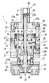
図1〜図3において1はケーシングであって、内部にシリンダ孔2を有する角柱形の第1部分1aと、この第1部分1aの一端に取り付けられて上記シリンダ孔2を塞ぐ、円板の一部を直線状に切除した形の第2部分1bとで構成されており、この第2部分1bの外面には、小円筒形をした位置検出部3が外部に突出するように形成されている。
【0012】
上記ケーシング1の内部には、大径の第1エアシリンダ機構5と小径の第2エアシリンダ機構6とが内外同軸状に組み込まれている。
【0013】
上記第1エアシリンダ機構5は、チャックヘッド10を前後進させるためのストローク用のエアシリンダ機構であって、上記シリンダ孔2内に摺動自在に収容された大径の第1ピストン11と、該第1ピストン11に基端部を連結されて先端部が上記シリンダ孔2から気密にかつ摺動自在に突出する大径の第1ロッド12とを有している。上記第1ピストン11は、やや長めの円筒形をしていて、その内部に形成されたシリンダ孔13と、このシリンダ孔13の一端を閉じるカバー14とを有し、該第1ピストン11の外周には、相互間に所要の間隔を保って2つのパッキン15が取り付けられ、これらのパッキン15によって該第1ピストン11の両側に一対の圧力室16a,16bが区画されている。
【0014】
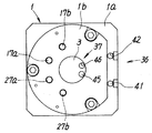
上記各圧力室16a,16bに圧縮空気を供給するためのストローク用のポート17a,17bは、図2から分かるようにケーシング1の上面に形成されていて、このうち一方のポート17aが通孔18を通じてヘッド側の圧力室16aに連通し、他方のポート17bが通孔19を通じてロッド側の圧力室16bに連通している。
【0015】
また、上記第1ピストン11の外周面の一部には、軸線方向に係止溝20が設けられ、これに対してケーシング1側には、この係止溝20に先端が係合する係止部材21がねじ着けられ、これらの係止溝20と係止部材21とによって第1ピストン11の回転を防止するための回り止めが構成されている。
【0016】
一方、上記第2エアシリンダ機構6は、ワークをチャックしたり解放したりするためのチャック用のエアシリンダ機構であって、上記第1ピストン11の内部のシリンダ孔13内に摺動自在に収容された小径の第2ピストン22と、該第2ピストン22の中心部に固定的に取り付けられて該第2ピストン22から両方向に延出する小径の第2ロッド23とを有している。上記第2ピストン22の外周には一つのパッキン15が取り付けられ、このパッキン15によって該第2ピストン22の両側に一対の圧力室26a,26bが区画されている。また、上記第2ロッド23の先端部23aは、上記第1ロッド12を貫通するように延伸し、第2ロッド23の基端部23bは、上記第1ピストン11のカバー14を気密にかつ摺動自在に貫通して、ケーシング1の第2部分1bに形成された上記位置検出部3内に嵌合する位置まで延伸している。
【0017】
上記各圧力室26a,26bに圧縮空気を供給するためのチャック用のポート27a,27bは、図2に示すようにケーシング1の上面に形成されていて、一方のポート27aが通孔28を通じてヘッド側の圧力室26aに連通し、他方のポート27bが通孔29を通じてロッド側の圧力室26bに連通している。
【0018】
かくして、2組のエアシリンダ機構5,6に圧縮空気を供給するストローク用ポート17a,17bとチャック用ポート27a,27bとをケーシング1の上面に集中的に設けることにより、各ポートへのエア配管を一方向だけにまとめることができるため、配管作業や保守管理作業が容易になる。
【0019】
上記第1エアシリンダ機構5における第1ロッド12の先端には、短円柱形をした上記チャックヘッド10が取り付けられ、第1ロッド12の伸縮によりこのチャックヘッド10が前後動するようになっている。このチャックヘッド10には、ワーク把持用の複数のジョー部材30,30が、第2ロッド23の軸線を中心にした放射方向への変移により相互に開閉自在なるように取り付けられると共に、この第2ロッド23の伸縮動作をこれらのジョー部材30,30の開閉動作に変換する変換機構32が設けられている。
【0020】
上記変換機構32はカム式のもので、第2ロッド23の先端部に各ジョー部材30,30に対応するように形成された複数のカム33と、各ジョー部材30,30の内側端に形成されたカム溝34とからなっている。上記カム33は、先端側が次第にロッド23の中心に近づく方向に傾斜し、カム溝34も該カム33と同じ方向に傾斜していて、対応する各カム33とカム溝34とが摺動自在に係合している。そして上記第2ロッド23が伸長すると、各カム33がカム溝34の傾斜面を摺動してジョー部材30,30を外側に押し動かすため各ジョー部材30,30間の間隔が広がり、第2ロッド23が短縮すると、各カム33がジョー部材30,30を内側に引き寄せるためそれらの間隔が狭められ、このとき、各ジョー部材30,30に取り付けた治具によってワークがチャックされたり解放されたりするものである。
【0021】
上記エアチャックにはまた、第1エアシリンダ機構5が動作したときのチャックヘッド10のストローク位置を検出するストローク位置検出手段36と、第1エアシリンダ機構5が動作したときのジョー部材30,30の開閉位置を検出するチャック位置検出手段37とが付設されている。
【0022】
上記ストローク位置検出手段36は、第1ピストン11の外周に取り付けられたマグネットからなる被検出部材40と、上記ケーシング1の外面のセンサー取付溝42内に取り付けられて上記被検出部材40からの磁気を検出する位置センサー41とで構成されている。ここで、チャックヘッド10の両方のストローク端での位置を検出する場合は、上記位置センサー41を2つの取付溝40,40内の両ストローク端に対応する位置に1つずつ設ければ良く、何れか一方のストローク端だけを検出する場合にはそのストローク端に対応する位置に1つ設ければ良い。あるいは、チャックヘッド10の全ストローク中の磁気を検出できる位置センサーを1つだけ設け、その磁気の変化からストローク中の全位置を検出するように構成することもできる。
【0023】
一方のチャック位置検出手段37は、上記第2ロッド23の基端部端面に取り付けられたマグネットからなる被検出部材44と、ケーシング1の位置検出部3の外側面に形成されたセンサー取付溝46内に取り付けられて上記被検出部材44からの磁気を検出する位置センサー45とで構成されている。この場合の位置センサー45を設ける位置や数等については、上記ストローク位置検出手段36の場合と同じである。
【0024】
なお、上記各位置検出手段36及び37は、上述したようにマグネットと磁気センサーとからなる磁気検出方式のものに限定されず、静電容量の変化を検出するものや、インピーダンスの変化を検出するもの、あるいは光学式のもなど、他の検出方式のものを用いることもできる。
【0025】
上記構成を有する複合型エアチャックは、ケーシング1の上面に設けた一対のストローク用ポート17a,17bから第1エアシリンダ機構5の2つの圧力室16a,16bに交互に圧縮空気を供給することにより、第1ピストン11及び第1ロッド12を動作させてチャックヘッド10を前後動させることができ、また、一対のチャック用ポート27a,27bから第2エアシリンダ機構6の2つの圧力室26a,26bに交互に圧縮空気を供給することにより、第2ピストン22及び第2ロッド23を動作させて上記チャックヘッド10上の複数のジョー部材30,30を開閉させることができる。そして、これらの動作を複合させることにより、上記ジョー部材30,30でワークをチャックして持ち上げたり、チャックしたワークを所定の場所に降ろして解放するといったような操作を行うものである。
【0026】
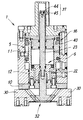
上記動作を具体的に示すため、図1には、第1エアシリンダ機構5の第1ロッド12を伸長してチャックヘッド10を前進させ、第2エアシリンダ機構6の第2ロッド23は後退させてジョー部材30,30を閉じた場合が示されている。また図4には、第1エアシリンダ機構5の第1ロッド12を伸長させてチャックヘッド10を前進させると共に、第2エアシリンダ機構6の第2ロッド23も前進させてジョー部材30,30を開いた場合が示されている。さらに図5には、第1エアシリンダ機構5の第1ロッド12を短縮してチャックヘッド10を後退させ、第2エアシリンダ機構6の第2ロッド23は前進させてジョー部材30,30を開いた場合が示されている。また図6には、第1エアシリンダ機構5の第1ロッド12を短縮してチャックヘッド10を後退させ、第2エアシリンダ機構6の第2ロッド23も後退させてジョー部材30,30を閉じた場合が示されている。
【0027】
上記チャックヘッド10が前後進してストローク端に到達したときの位置検出は、ストローク位置検出手段36で第1ピストン11の動作位置を検出することにより行われる。
【0028】
一方、ジョー部材30,30が開閉したときの位置検出は、チャック位置検出手段37で第2ロッド23の動作位置を検出することにより間接的に行われる。この場合、該第2ロッド23は、第1エアシリンダ機構5の第1ピストン11が前後動するときこの第1ピストン11と一緒に前後動するため、上記図1及び図4〜図6から分かるように、該第2ロッド23の前進ストローク端の位置と後退ストローク端の位置がそれぞれ、第1ピストン11が前進した状態と後退した状態とで異なることになる。そこで例えば、この第2ロッド23の図1及び図4に示す動作位置を検出する場合は、位置検出部3に設けた2つのセンサー取付溝46,46内の上記動作位置と対応する部分にそれぞれ位置センサー45を取り付け、第1エアシリンダ機構5の各圧力室16a,16bに圧縮空気が供給されたことを検出してその供給信号と上記位置センサー45からの位置信号とを関連付けることにより、第2ロッド23の上記動作位置を検出することができる。
【0029】
【発明の効果】
このように本発明によれば、チャック用エアシリンダ機構とストローク用エアシリンダ機構とをケーシング内に内外同軸状に組み込んだ複合型エアチャックであっても、チャック用エアシリンダ機構のロッドを利用した簡単な構成により、ジョー部材によるワークのチャック動作を確実に検出することができる。
【図面の簡単な説明】
【図1】 本発明に係る複合型エアチャックの一実施例を示す縦断面図である。
【図2】 図1の平面図である。
【図3】 図1の下面図である。
【図4】 上記エアチャックの異なる動作状態を示す縦断面図である。
【図5】 上記エアチャックのさらに異なる動作状態を示す縦断面図である。
【図6】 上記エアチャックのさらに異なる動作状態を示す縦断面図である。[0001]
BACKGROUND OF THE INVENTION
The present invention relates to a composite air chuck provided with a position detection mechanism for detecting a chuck position of a workpiece by a jaw member.
[0002]
[Prior art]
A composite type air chuck having a chuck function for chucking a workpiece and a stroke function for moving the chucked workpiece in the front-rear direction is known as disclosed in, for example, Japanese Patent Application Laid-Open No. 8-19983. In this air chuck, a stroke air cylinder mechanism composed of a large diameter piston and a large diameter rod and a chuck air cylinder mechanism composed of a small diameter piston and a small diameter rod are coaxially and internally and externally arranged in a casing. The chuck head is attached to the rod of the stroke air cylinder mechanism, and a plurality of jaw members for gripping the workpiece are attached to the chuck head so as to be openable and closable, and these jaw members are attached by the rod of the chuck air cylinder mechanism. It is designed to open and close.
[0003]
In such an air chuck, generally, a position detection mechanism including a magnet and a magnetic sensor is attached to detect that the jaw member has chucked or released the workpiece and to generate a control signal for automatic operation. . Specifically, a magnet is attached to the jaw member and a sensor is attached to the casing to directly detect the operating position of the jaw member, or a magnet is attached to the piston of the chuck air cylinder mechanism to detect the operating position of this piston. Thus, the open / close position of the jaw member is indirectly detected.
[0004]
However, in the conventional composite air chuck, the chuck head that holds the jaw member is driven by the stroke air cylinder mechanism, so a sensor is attached to the moving chuck head to change the operating position of the jaw member. It is difficult to detect directly. Further, the piston and rod of the chuck air cylinder mechanism are incorporated into the piston and rod of the stroke air cylinder mechanism, so that the stroke air cylinder mechanism is interposed between the chuck air cylinder mechanism and the casing. Therefore, it is difficult to detect the position of the piston of the chuck air cylinder mechanism.
[0005]
[Problems to be solved by the invention]
A technical problem of the present invention is that a chucking operation of a workpiece by a jaw member is performed with a simple configuration in a composite type air chuck in which an air cylinder mechanism for a chuck and an air cylinder mechanism for a stroke are incorporated inside and outside the casing in a coaxial manner. The purpose is to ensure detection.
[0006]
[Means for Solving the Problems]
In order to solve the above problems, a composite air chuck according to the present invention includes a casing having a cylinder hole therein; a first piston having a large diameter slidably received in the cylinder hole of the casing; and the first piston A first air cylinder mechanism for stroke having a large diameter first rod connected to the base end and having a distal end portion extending from the casing; and is slidable coaxially within the first piston. A small-diameter second piston housed in this manner, and a tip end portion extending into the first rod connected to the second piston, and a base end portion projecting from the first piston so as to detect the position of the casing A second air cylinder mechanism for a chuck having a small-diameter second rod extending to a position facing the cylinder; a chuck attached to the tip of the first rod and moving back and forth by the expansion and contraction of the first rod A plurality of jaw members for gripping a workpiece attached to the chuck head so as to be freely opened and closed; an extension operation of the second rod interposed between the jaw member and the second rod in the chuck head A conversion mechanism that converts the opening / closing operation of the jaw member; a detected member attached to the proximal end portion of the second rod; and a position sensor attached to the position detection portion of the casing to detect the detected member A chuck position detecting means for detecting an open / close position of the jaw member; a detected member attached to the first piston, and a position sensor attached to the casing to detect the detected member. Stroke position detecting means for detecting the stroke position of the chuck head .
[0007]
The composite air chuck of the present invention having the above-described configuration extends the base end portion of the second rod in the second air cylinder mechanism from the first piston of the second air cylinder mechanism to a position facing the position detection portion of the casing. The first air cylinder mechanism is incorporated into the second air cylinder mechanism with a simple configuration in which a detection target member is attached to the base end portion and a position sensor is attached to the position detection portion of the casing. However, it is possible to indirectly detect the open / close position of the jaw member by detecting the operating position of the rod of the first air cylinder mechanism without making significant modifications to it.
[0009]
According to a preferred embodiment of the present invention, the air chuck compresses a pair of stroke ports for supplying compressed air to the pressure chambers on both sides of the first piston and the pressure chambers on both sides of the second piston. A pair of chuck ports for supplying air is provided, and these ports are concentrated on the end surface of the casing opposite to the side on which the jaw member is provided.
[0010]
DETAILED DESCRIPTION OF THE INVENTION
Hereinafter, a preferred exemplary embodiment of a composite type air chuck with a position detection mechanism according to the present invention will be described in detail with reference to the drawings.
[0011]
1 to 3, reference numeral 1 denotes a casing, which is a prismatic first portion 1a having a
[0012]
Inside the casing 1, a large-diameter first
[0013]
The first
[0014]
[0015]
In addition, a
[0016]
On the other hand, the second
[0017]
Chuck
[0018]
Thus, the
[0019]
The
[0020]
The
[0021]
The air chuck also includes a stroke position detecting means 36 for detecting a stroke position of the
[0022]
The stroke position detecting means 36 is attached to the detected
[0023]
One chuck position detecting means 37 includes a detected
[0024]
Each of the position detection means 36 and 37 is not limited to a magnetic detection type consisting of a magnet and a magnetic sensor as described above, and detects a change in capacitance or a change in impedance. It is also possible to use other detection methods such as optical ones or optical ones.
[0025]
The composite type air chuck having the above configuration supplies compressed air to the two
[0026]
In order to specifically show the above operation, FIG. 1 shows that the
[0027]
The position detection when the
[0028]
On the other hand, the position detection when the
[0029]
【The invention's effect】
As described above, according to the present invention, the rod of the chuck air cylinder mechanism is used even in the combined air chuck in which the chuck air cylinder mechanism and the stroke air cylinder mechanism are coaxially incorporated in the casing. With a simple configuration, it is possible to reliably detect the chucking operation of the workpiece by the jaw member.
[Brief description of the drawings]
FIG. 1 is a longitudinal sectional view showing an embodiment of a composite air chuck according to the present invention.
FIG. 2 is a plan view of FIG.
FIG. 3 is a bottom view of FIG. 1;
FIG. 4 is a longitudinal sectional view showing different operating states of the air chuck.
FIG. 5 is a longitudinal sectional view showing still another operation state of the air chuck.
FIG. 6 is a longitudinal sectional view showing still another operation state of the air chuck.
Claims (2)
上記ケーシングのシリンダ孔内に摺動自在に収容された大径の第1ピストンと、該第1ピストンに基端部を連結されて先端部が上記ケーシングから延出する大径の第1ロッドとを備えたストローク用の第1エアシリンダ機構;
上記第1ピストンの内部に同軸方向に摺動自在なるように収容された小径の第2ピストンと、該第2ピストンに連結されて先端部が上記第1ロッドの内部に延伸すると共に、基端部が上記第1ピストンから突出してケーシングの位置検出部に臨む位置まで延伸する小径の第2ロッドとを備えたチャック用の第2エアシリンダ機構;
上記第1ロッドの先端に取り付けられて該第1ロッドの伸縮により前後動するチャックヘッド;
上記チャックヘッドに開閉自在なるように取り付けられたワーク把持用の複数のジョー部材;
上記チャックヘッド内においてジョー部材と第2ロッドとの間に介設され、該第2ロッドの伸縮動作をジョー部材の開閉動作に変換する変換機構;
上記第2ロッドの基端部に取り付けられた被検出部材と、上記ケーシングの位置検出部に取り付けられて上記被検出部材を検出する位置センサーとからなる、上記ジョー部材の開閉位置を検出するためのチャック位置検出手段;
上記第1ピストンに取り付けられた被検出部材と、上記ケーシングに取り付けられて上記被検出部材を検出する位置センサーとからなる、上記チャックヘッドのストローク位置を検出するためのストローク位置検出手段;
を有することを特徴とする位置検出機構付き複合型エアチャック。Casing with cylinder bore inside;
A large-diameter first piston slidably accommodated in a cylinder hole of the casing; a large-diameter first rod having a base end connected to the first piston and having a distal end extending from the casing; A first air cylinder mechanism for stroke comprising:
A small-diameter second piston housed in the first piston so as to be slidable in the coaxial direction; a distal end portion connected to the second piston and extending into the first rod; A second air cylinder mechanism for chuck comprising a second rod having a small diameter extending from the first piston to a position facing the position detection portion of the casing;
A chuck head attached to the tip of the first rod and moving back and forth by expansion and contraction of the first rod;
A plurality of jaw members for gripping a workpiece attached to the chuck head so as to be freely opened and closed;
A conversion mechanism that is interposed between the jaw member and the second rod in the chuck head and converts an expansion / contraction operation of the second rod into an opening / closing operation of the jaw member;
In order to detect the open / close position of the jaw member, comprising a detected member attached to the base end portion of the second rod and a position sensor attached to the position detecting portion of the casing to detect the detected member. Chuck position detecting means;
Stroke position detecting means for detecting the stroke position of the chuck head, comprising: a detected member attached to the first piston; and a position sensor attached to the casing to detect the detected member;
A composite air chuck with a position detection mechanism.
Priority Applications (5)
| Application Number | Priority Date | Filing Date | Title |
|---|---|---|---|
| JP28289199A JP4122490B2 (en) | 1999-10-04 | 1999-10-04 | Combined type air chuck with position detection mechanism |
| US09/664,853 US6478310B1 (en) | 1999-10-04 | 2000-09-19 | Combination pneumatic chuck with position detecting mechanism |
| CN00128893A CN1290592A (en) | 1999-10-04 | 2000-09-28 | Composite pneumatic chuck with position detection mechanism |
| DE10049262A DE10049262A1 (en) | 1999-10-04 | 2000-09-28 | Pneumatic chuck with position detection mechanism, with casing, two cylinder mechanisms, several claw elements and resetting mechanism |
| KR1020000057229A KR100366002B1 (en) | 1999-10-04 | 2000-09-29 | Combination pneumatic chuck with position detecting mechanism |
Applications Claiming Priority (1)
| Application Number | Priority Date | Filing Date | Title |
|---|---|---|---|
| JP28289199A JP4122490B2 (en) | 1999-10-04 | 1999-10-04 | Combined type air chuck with position detection mechanism |
Publications (3)
| Publication Number | Publication Date |
|---|---|
| JP2001105375A JP2001105375A (en) | 2001-04-17 |
| JP2001105375A5 JP2001105375A5 (en) | 2006-05-18 |
| JP4122490B2 true JP4122490B2 (en) | 2008-07-23 |
Family
ID=17658449
Family Applications (1)
| Application Number | Title | Priority Date | Filing Date |
|---|---|---|---|
| JP28289199A Expired - Fee Related JP4122490B2 (en) | 1999-10-04 | 1999-10-04 | Combined type air chuck with position detection mechanism |
Country Status (5)
| Country | Link |
|---|---|
| US (1) | US6478310B1 (en) |
| JP (1) | JP4122490B2 (en) |
| KR (1) | KR100366002B1 (en) |
| CN (1) | CN1290592A (en) |
| DE (1) | DE10049262A1 (en) |
Families Citing this family (22)
| Publication number | Priority date | Publication date | Assignee | Title |
|---|---|---|---|---|
| DE10150710A1 (en) * | 2001-10-13 | 2003-04-17 | Heller Geb Gmbh Maschf | Rotating machine element and method for detecting position values of at least one function carrier of such a rotating machine element |
| DE10307565A1 (en) * | 2002-10-09 | 2004-04-22 | Smw-Autoblok Spannsysteme Gmbh | Heavy duty chuck or similar has pressure sensor for monitoring pressure in pressure chambers associated with one or both pistons, receiver connected to unit for evaluating pressure sensor signals |
| US20080107548A1 (en) * | 2006-11-02 | 2008-05-08 | Stephens Dynamics, Inc. | Rotary reciprocating intensified hydraulic actuator |
| US8070463B2 (en) * | 2006-11-02 | 2011-12-06 | Stephens Gregory A | Rotary reciprocating intensified hydraulic actuator |
| ATE489194T1 (en) * | 2007-10-16 | 2010-12-15 | Roehm Gmbh | METHOD FOR CLAMPING DEFORMATION-SENSITIVE WORKPIECES AND CLAMPING CHUCKS FOR IMPLEMENTING THE METHOD |
| CN101653938B (en) * | 2008-08-22 | 2012-12-12 | 比亚迪股份有限公司 | Detectable gripper, detectable manipulator and detection method thereof |
| DE102009007657A1 (en) * | 2009-02-05 | 2010-08-12 | Wabco Gmbh | Piston-cylinder arrangement with integrated measuring device |
| DE102009044167A1 (en) * | 2009-10-02 | 2011-04-07 | Röhm Gmbh | Method for clamping a tool or a workpiece and device for carrying out the method |
| KR101336538B1 (en) | 2011-12-23 | 2013-12-03 | 현대위아 주식회사 | Workpiece clamping/unclaimping detecting device |
| CN103112009B (en) * | 2012-12-27 | 2016-01-20 | 宁波大正工业机器人技术有限公司 | A kind of autoloader finger cylinder special detection device and detection method |
| JP6191292B2 (en) * | 2013-07-10 | 2017-09-06 | Smc株式会社 | Machine tool chuck device and machine tool chuck method |
| CN103753401B (en) * | 2014-01-23 | 2016-08-17 | 沈阳海默数控机床有限公司 | A kind of internal grinder Special rotary distributing device |
| CN104179664A (en) * | 2014-08-25 | 2014-12-03 | 重庆耐德燃气设备有限公司 | Compression cylinder of hydraulic piston type natural gas compressor |
| KR101800614B1 (en) | 2015-09-18 | 2017-11-22 | (주)주강로보테크 | Mechanism for adjusting the position sensing device for detecting the stroke position of the air chuck jaw |
| KR102409899B1 (en) * | 2016-10-05 | 2022-06-15 | 가부시키가이샤 기타가와 뎃꼬쇼 | gripper |
| CN106391913B (en) * | 2016-11-10 | 2018-07-20 | 华南理工大学 | It is a kind of that the three-dimensional internally finned tube molding machine cut-squeezed and method are ploughed based on multiple-cutting-edge |
| CN107654442B (en) * | 2017-08-14 | 2020-04-17 | 芜湖慧盈自动化设备有限公司 | Air cylinder assembly capable of transmitting air and arranged at tail end of industrial robot |
| CN107437883A (en) * | 2017-08-22 | 2017-12-05 | 宁波鼎祥电器制造有限公司 | Stepper motor |
| JP6867340B2 (en) * | 2018-08-08 | 2021-04-28 | Ckd株式会社 | Gripping device |
| JP7101987B2 (en) * | 2018-10-18 | 2022-07-19 | 中村留精密工業株式会社 | Machine tool with spindle with measurement function |
| US11123832B2 (en) * | 2018-10-18 | 2021-09-21 | Nakamura-Tome Precision Industry Co., Ltd. | Workpiece holding device and loading apparatus that uses the workpiece holding device |
| CN110328611A (en) * | 2019-07-25 | 2019-10-15 | 德屹智能科技(扬州)有限公司 | Clamp the robot polishing handgrip of circular feature workpiece |
Family Cites Families (7)
| Publication number | Priority date | Publication date | Assignee | Title |
|---|---|---|---|---|
| US4080716A (en) * | 1977-04-25 | 1978-03-28 | Wilhelm Hegenscheidt Gesellschaft Mbh | Method for controlling proper clamping of a workpiece in a clamping device |
| DE3004988C2 (en) * | 1980-02-11 | 1987-10-01 | Gildemeister Ag, 4800 Bielefeld | Device for setting two final clamping positions that limit a clamping stroke |
| JPS63122902A (en) * | 1986-11-13 | 1988-05-26 | Ckd Controls Ltd | Apparatus for confirming position of moving body |
| DE3719102A1 (en) * | 1987-06-06 | 1988-12-15 | Smw Spanneinrichtungen | CIRCULATING CLAMPING CYLINDERS FOR POWER CHUCK |
| SE501291C2 (en) * | 1992-09-23 | 1995-01-09 | Mecman Ab Rexroth | Device for positioning piston cylinder assemblies |
| JPH0819983A (en) | 1994-07-04 | 1996-01-23 | Smc Corp | Hydraulic chuck having stroke mechanism |
| JP3822259B2 (en) * | 1995-01-17 | 2006-09-13 | Smc株式会社 | Cylinder device |
-
1999
- 1999-10-04 JP JP28289199A patent/JP4122490B2/en not_active Expired - Fee Related
-
2000
- 2000-09-19 US US09/664,853 patent/US6478310B1/en not_active Expired - Lifetime
- 2000-09-28 CN CN00128893A patent/CN1290592A/en active Pending
- 2000-09-28 DE DE10049262A patent/DE10049262A1/en not_active Withdrawn
- 2000-09-29 KR KR1020000057229A patent/KR100366002B1/en active IP Right Grant
Also Published As
| Publication number | Publication date |
|---|---|
| CN1290592A (en) | 2001-04-11 |
| KR100366002B1 (en) | 2002-12-26 |
| KR20010050731A (en) | 2001-06-15 |
| DE10049262A1 (en) | 2001-05-03 |
| JP2001105375A (en) | 2001-04-17 |
| US6478310B1 (en) | 2002-11-12 |
Similar Documents
| Publication | Publication Date | Title |
|---|---|---|
| JP4122490B2 (en) | Combined type air chuck with position detection mechanism | |
| JP4699433B2 (en) | Positioning clamp device | |
| US10953477B2 (en) | Air chuck provided with locking mechanism | |
| KR100951085B1 (en) | Positioning and clamping apparatus | |
| TW201420263A (en) | Fluid pressure cylinder and revolving clamp device | |
| JP2012166276A (en) | Rod position detector for clamping device | |
| JPS61159287A (en) | Actuator | |
| JP3479476B2 (en) | Booster type hydraulic cylinder device with lock mechanism | |
| US10626894B2 (en) | Fluid pressure cylinder and manufacturing method thereof | |
| JPS5915762B2 (en) | Mechanical hollow chuck | |
| GB2283189A (en) | Three fingered chuck | |
| JP6076380B2 (en) | Slide lock device for press machine | |
| JP2000107916A (en) | Four-jaw type automatic chucking device for machine tool | |
| KR200153136Y1 (en) | Air chuck | |
| JPH0819983A (en) | Hydraulic chuck having stroke mechanism | |
| JP3940865B2 (en) | 3-jaw open / close chuck | |
| KR900007520B1 (en) | Automatic centering fluid pressured chuck | |
| JP7344544B2 (en) | swing clamp | |
| KR100900736B1 (en) | Door fastening device | |
| JP6590217B2 (en) | Cylinder device | |
| JP3051714B2 (en) | Opening and closing chuck | |
| JP2004223661A (en) | Clamp device | |
| ITBS20000114A1 (en) | SELF-CENTERING SPINDLE PARTICULARLY FOR TURNING WHEEL RIMS | |
| JPH0217761Y2 (en) | ||
| JPS6035524Y2 (en) | Full processing chuck device |
Legal Events
| Date | Code | Title | Description |
|---|---|---|---|
| A521 | Request for written amendment filed |
Free format text: JAPANESE INTERMEDIATE CODE: A523 Effective date: 20060327 |
|
| A621 | Written request for application examination |
Free format text: JAPANESE INTERMEDIATE CODE: A621 Effective date: 20060327 |
|
| A977 | Report on retrieval |
Free format text: JAPANESE INTERMEDIATE CODE: A971007 Effective date: 20070723 |
|
| A131 | Notification of reasons for refusal |
Free format text: JAPANESE INTERMEDIATE CODE: A131 Effective date: 20070731 |
|
| A521 | Request for written amendment filed |
Free format text: JAPANESE INTERMEDIATE CODE: A523 Effective date: 20070928 |
|
| TRDD | Decision of grant or rejection written | ||
| A01 | Written decision to grant a patent or to grant a registration (utility model) |
Free format text: JAPANESE INTERMEDIATE CODE: A01 Effective date: 20080318 |
|
| A01 | Written decision to grant a patent or to grant a registration (utility model) |
Free format text: JAPANESE INTERMEDIATE CODE: A01 |
|
| A61 | First payment of annual fees (during grant procedure) |
Free format text: JAPANESE INTERMEDIATE CODE: A61 Effective date: 20080418 |
|
| R150 | Certificate of patent or registration of utility model |
Ref document number: 4122490 Country of ref document: JP Free format text: JAPANESE INTERMEDIATE CODE: R150 Free format text: JAPANESE INTERMEDIATE CODE: R150 |
|
| FPAY | Renewal fee payment (event date is renewal date of database) |
Free format text: PAYMENT UNTIL: 20110516 Year of fee payment: 3 |
|
| FPAY | Renewal fee payment (event date is renewal date of database) |
Free format text: PAYMENT UNTIL: 20120516 Year of fee payment: 4 |
|
| R250 | Receipt of annual fees |
Free format text: JAPANESE INTERMEDIATE CODE: R250 |
|
| FPAY | Renewal fee payment (event date is renewal date of database) |
Free format text: PAYMENT UNTIL: 20130516 Year of fee payment: 5 |
|
| R250 | Receipt of annual fees |
Free format text: JAPANESE INTERMEDIATE CODE: R250 |
|
| R250 | Receipt of annual fees |
Free format text: JAPANESE INTERMEDIATE CODE: R250 |
|
| R250 | Receipt of annual fees |
Free format text: JAPANESE INTERMEDIATE CODE: R250 |
|
| R250 | Receipt of annual fees |
Free format text: JAPANESE INTERMEDIATE CODE: R250 |
|
| R250 | Receipt of annual fees |
Free format text: JAPANESE INTERMEDIATE CODE: R250 |
|
| R250 | Receipt of annual fees |
Free format text: JAPANESE INTERMEDIATE CODE: R250 |
|
| R250 | Receipt of annual fees |
Free format text: JAPANESE INTERMEDIATE CODE: R250 |
|
| LAPS | Cancellation because of no payment of annual fees |