JP4120969B2 - Ultrasonic test method and ultrasonic test apparatus using the same - Google Patents
Ultrasonic test method and ultrasonic test apparatus using the same Download PDFInfo
- Publication number
- JP4120969B2 JP4120969B2 JP2005195598A JP2005195598A JP4120969B2 JP 4120969 B2 JP4120969 B2 JP 4120969B2 JP 2005195598 A JP2005195598 A JP 2005195598A JP 2005195598 A JP2005195598 A JP 2005195598A JP 4120969 B2 JP4120969 B2 JP 4120969B2
- Authority
- JP
- Japan
- Prior art keywords
- ultrasonic
- probe
- test body
- wave
- ultrasonic wave
- Prior art date
- Legal status (The legal status is an assumption and is not a legal conclusion. Google has not performed a legal analysis and makes no representation as to the accuracy of the status listed.)
- Active
Links
- 238000012360 testing method Methods 0.000 title claims description 87
- 238000010998 test method Methods 0.000 title claims description 17
- 239000000523 sample Substances 0.000 claims description 66
- 239000000463 material Substances 0.000 claims description 20
- 230000010355 oscillation Effects 0.000 claims description 9
- 230000001902 propagating effect Effects 0.000 claims description 8
- 230000000644 propagated effect Effects 0.000 claims description 7
- 238000002604 ultrasonography Methods 0.000 claims 4
- 239000004918 carbon fiber reinforced polymer Substances 0.000 description 6
- 230000005540 biological transmission Effects 0.000 description 3
- 238000001514 detection method Methods 0.000 description 3
- 230000007547 defect Effects 0.000 description 2
- 238000007689 inspection Methods 0.000 description 2
- 238000005452 bending Methods 0.000 description 1
- 230000008878 coupling Effects 0.000 description 1
- 238000010168 coupling process Methods 0.000 description 1
- 238000005859 coupling reaction Methods 0.000 description 1
- 230000001066 destructive effect Effects 0.000 description 1
- 238000010586 diagram Methods 0.000 description 1
- 230000000694 effects Effects 0.000 description 1
- 238000000034 method Methods 0.000 description 1
Images


Classifications
-
- G—PHYSICS
- G01—MEASURING; TESTING
- G01N—INVESTIGATING OR ANALYSING MATERIALS BY DETERMINING THEIR CHEMICAL OR PHYSICAL PROPERTIES
- G01N29/00—Investigating or analysing materials by the use of ultrasonic, sonic or infrasonic waves; Visualisation of the interior of objects by transmitting ultrasonic or sonic waves through the object
- G01N29/22—Details, e.g. general constructional or apparatus details
- G01N29/24—Probes
- G01N29/2456—Focusing probes
-
- G—PHYSICS
- G01—MEASURING; TESTING
- G01N—INVESTIGATING OR ANALYSING MATERIALS BY DETERMINING THEIR CHEMICAL OR PHYSICAL PROPERTIES
- G01N29/00—Investigating or analysing materials by the use of ultrasonic, sonic or infrasonic waves; Visualisation of the interior of objects by transmitting ultrasonic or sonic waves through the object
- G01N29/22—Details, e.g. general constructional or apparatus details
- G01N29/223—Supports, positioning or alignment in fixed situation
-
- G—PHYSICS
- G01—MEASURING; TESTING
- G01N—INVESTIGATING OR ANALYSING MATERIALS BY DETERMINING THEIR CHEMICAL OR PHYSICAL PROPERTIES
- G01N29/00—Investigating or analysing materials by the use of ultrasonic, sonic or infrasonic waves; Visualisation of the interior of objects by transmitting ultrasonic or sonic waves through the object
- G01N29/22—Details, e.g. general constructional or apparatus details
- G01N29/24—Probes
- G01N29/2487—Directing probes, e.g. angle probes
-
- G—PHYSICS
- G01—MEASURING; TESTING
- G01N—INVESTIGATING OR ANALYSING MATERIALS BY DETERMINING THEIR CHEMICAL OR PHYSICAL PROPERTIES
- G01N2291/00—Indexing codes associated with group G01N29/00
- G01N2291/02—Indexing codes associated with the analysed material
- G01N2291/023—Solids
- G01N2291/0231—Composite or layered materials
-
- G—PHYSICS
- G01—MEASURING; TESTING
- G01N—INVESTIGATING OR ANALYSING MATERIALS BY DETERMINING THEIR CHEMICAL OR PHYSICAL PROPERTIES
- G01N2291/00—Indexing codes associated with group G01N29/00
- G01N2291/04—Wave modes and trajectories
- G01N2291/042—Wave modes
- G01N2291/0425—Parallel to the surface, e.g. creep waves
-
- G—PHYSICS
- G01—MEASURING; TESTING
- G01N—INVESTIGATING OR ANALYSING MATERIALS BY DETERMINING THEIR CHEMICAL OR PHYSICAL PROPERTIES
- G01N2291/00—Indexing codes associated with group G01N29/00
- G01N2291/04—Wave modes and trajectories
- G01N2291/042—Wave modes
- G01N2291/0427—Flexural waves, plate waves, e.g. Lamb waves, tuning fork, cantilever
-
- G—PHYSICS
- G01—MEASURING; TESTING
- G01N—INVESTIGATING OR ANALYSING MATERIALS BY DETERMINING THEIR CHEMICAL OR PHYSICAL PROPERTIES
- G01N2291/00—Indexing codes associated with group G01N29/00
- G01N2291/04—Wave modes and trajectories
- G01N2291/056—Angular incidence, angular propagation
-
- G—PHYSICS
- G01—MEASURING; TESTING
- G01N—INVESTIGATING OR ANALYSING MATERIALS BY DETERMINING THEIR CHEMICAL OR PHYSICAL PROPERTIES
- G01N2291/00—Indexing codes associated with group G01N29/00
- G01N2291/10—Number of transducers
- G01N2291/101—Number of transducers one transducer
-
- G—PHYSICS
- G01—MEASURING; TESTING
- G01N—INVESTIGATING OR ANALYSING MATERIALS BY DETERMINING THEIR CHEMICAL OR PHYSICAL PROPERTIES
- G01N2291/00—Indexing codes associated with group G01N29/00
- G01N2291/26—Scanned objects
- G01N2291/269—Various geometry objects
- G01N2291/2693—Rotor or turbine parts
-
- G—PHYSICS
- G01—MEASURING; TESTING
- G01N—INVESTIGATING OR ANALYSING MATERIALS BY DETERMINING THEIR CHEMICAL OR PHYSICAL PROPERTIES
- G01N2291/00—Indexing codes associated with group G01N29/00
- G01N2291/26—Scanned objects
- G01N2291/269—Various geometry objects
- G01N2291/2694—Wings or other aircraft parts
Landscapes
- Physics & Mathematics (AREA)
- Health & Medical Sciences (AREA)
- Life Sciences & Earth Sciences (AREA)
- Chemical & Material Sciences (AREA)
- Analytical Chemistry (AREA)
- Biochemistry (AREA)
- General Health & Medical Sciences (AREA)
- General Physics & Mathematics (AREA)
- Immunology (AREA)
- Pathology (AREA)
- Investigating Or Analyzing Materials By The Use Of Ultrasonic Waves (AREA)
Description
本発明は、超音波の送信又は受信を行う探触子と板波を伝搬する試験体との間で超音波を伝搬させて前記試験体を試験する超音波試験方法及びこれを用いた超音波試験装置に関する。 The present invention relates to an ultrasonic test method for testing an ultrasonic wave by propagating an ultrasonic wave between a probe that transmits or receives ultrasonic waves and a test body that propagates plate waves, and an ultrasonic wave using the ultrasonic test method. It relates to a test apparatus.
図7に示すように、空気中を伝搬する超音波を用いた試験方法において、探触子から試験体へ超音波を伝搬させて板波を発生させ、又は、試験体に生じる板波を探触子で受信する方法が知られている(特許文献1参照)。
また、水平方向に湾曲する探触子を利用して入射・漏洩信号の送受信強度を向上させる試験方法については、非特許文献1に開示されている。
Further, Non-Patent
通常、この種の試験では探触子として単一方向に超音波を送受信するものが用いられている。したがって、この探触子からの超音波の前記伝搬時に、探触子から試験体への超音波の入射角θは単一状態をとることとなる。 Normally, in this type of test, a probe that transmits and receives ultrasonic waves in a single direction is used. Therefore, at the time of the propagation of the ultrasonic wave from the probe, the incident angle θ of the ultrasonic wave from the probe to the test body takes a single state.
ところで、例えば、図8,9に示すように、板波の周波数と板厚との積FT(KHzm)と超音波が実際に入射し板波を発生させうる入射角θ(°)との関係は、複数の板波のモード毎に異なる符号A0〜5,S0〜7の曲線で示される。したがって、符号S1のモードを例にとると、板波の周波数がF、板の厚さがT3であったとすると、FT3に対応する入射角θ3を探触子は維持する必要があり、治具等でこれを行っている。 By the way, for example, as shown in FIGS. 8 and 9, the relationship between the product FT (KHzm) of the plate wave frequency and the plate thickness and the incident angle θ (°) at which the ultrasonic wave is actually incident and the plate wave can be generated. Are indicated by curves of reference signs A0 to A5 and S0 to 7, which are different for each of a plurality of plate wave modes. Therefore, taking the mode of S1 as an example, if the frequency of the plate wave is F and the thickness of the plate is T3, the probe must maintain the incident angle θ3 corresponding to FT3. Etc. are doing this.
しかし、板厚がT=T3と予想していたところ、実際の入射部における板厚がT=T3+dT=T4である場合には、入射可能な入射角θ=θ4となり、超音波を試験体に入射させ、板波を発生させることが不可能となる。また、試験体表面の凹凸により入射角θが相対的に変動することにより、同様の現象で超音波を試験体に入射させ、板波を発生させることが不可能となる。さらに、上記相関は材質毎に異なる。その結果、板厚、材質等が異なる試験対象毎に探触子を調整せねばならず、また、材料の状態が大幅に変動することにより超音波探傷試験自体が不能となる不都合もあった。 However, when the plate thickness was expected to be T = T3, when the plate thickness at the actual incident portion is T = T3 + dT = T4, the incident angle θ = θ4 that can be incident, and ultrasonic waves are applied to the specimen. It is impossible to generate a plate wave by entering. In addition, since the incident angle θ is relatively changed due to the unevenness of the surface of the test body, it is impossible to cause the ultrasonic wave to enter the test body and generate a plate wave by the same phenomenon. Furthermore, the correlation differs for each material. As a result, the probe has to be adjusted for each test object having a different thickness, material, etc., and the ultrasonic flaw detection test itself becomes impossible due to a significant change in the state of the material.
かかる従来の実情に鑑みて、本発明は、試験体の厚みや表面の角度が変動しても探触子と試験体との間に板波を伝搬させることの可能な超音波試験方法及びこれを用いた超音波試験装置を提供することを目的とする。 In view of such a conventional situation, the present invention provides an ultrasonic test method capable of propagating a plate wave between a probe and a test body even when the thickness of the test body and the angle of the surface vary, and this An object of the present invention is to provide an ultrasonic test apparatus using the above.
上記目的を達成するため、本発明に係る超音波試験方法の特徴は、超音波の送信又は受信を行う探触子と板波を伝搬する試験体との間で超音波を伝搬させて前記試験体を試験する方法において、前記探触子は焦点型探触子であると共にこの探触子から試験体への超音波の入射角又は/及び試験体から探触子への超音波の受信可能角が同時に複数状態をとりうるものであり、超音波の伝搬経路に沿った基準軸を前記探触子の焦点を中心に揺動させる方向である揺動方向軸を超音波伝搬部の試験体表面を含む伝搬部表面と交差させるように前記探触子を配向してあり、前記探触子から超音波を送信し、超音波の入射位置における超音波の周波数と試験体の板厚との積に対応し前記試験体の材質毎に定まる入射角の超音波により特定のモードの板波を発生させ、この板波は前記試験体を伝搬し、伝搬した前記板波において、超音波の出射位置における超音波の周波数と試験体の板厚との積に対応し試験体の材質毎に定まる出射角の超音波を前記探触子により受信することにある。 In order to achieve the above object, the ultrasonic test method according to the present invention is characterized in that ultrasonic waves are propagated between a probe that transmits or receives ultrasonic waves and a test body that propagates plate waves. In the method of testing a body, the probe is a focus type probe and the incident angle of ultrasonic waves from the probe to the test body and / or reception of ultrasonic waves from the test body to the probe is possible. The test piece of the ultrasonic wave propagation part has a rocking direction axis which is a direction in which a reference axis along the ultrasonic wave propagation path is swung around the focal point of the probe, and the angle can take a plurality of states simultaneously. The probe is oriented so as to intersect the surface of the propagation part including the surface, ultrasonic waves are transmitted from the probe, and the frequency of the ultrasonic wave at the ultrasonic incident position and the plate thickness of the specimen Corresponding to the product, the plate wave of a specific mode by the ultrasonic wave of the incident angle determined for each material of the specimen This plate wave propagates through the test body, and in the propagated plate wave, the plate wave is determined for each material of the test body corresponding to the product of the ultrasonic frequency and the plate thickness of the test body. The ultrasonic wave of the emission angle is received by the probe.
例えば図2に示すように、振動子が湾曲した焦点型探触子を用いた場合は、湾曲の方向(超音波の伝搬経路に沿った基準軸Qを探触子の焦点Pを中心に揺動させる方向に沿った揺動方向軸)L1を焦点Pの近傍の伝搬部の試験体100の表面を含む伝搬部表面L2と交差させる。このような配置にすると、矢印に示すように、入射角θ(及び受信可能角)が中心軸の入射角θ=θ0を基準として複数状態をとりうる。その結果、図4に示すように、入射角θ1〜θ2の範囲に対応する周波数×板厚FT1〜FT2に関して超音波の伝搬が可能となる。
For example, as shown in FIG. 2, when a focus type probe having a curved transducer is used, the bending direction (the reference axis Q along the ultrasonic wave propagation path is swung around the focus P of the probe). The rocking direction axis L1 along the moving direction) intersects with the propagation portion surface L2 including the surface of the
前記探触子は、探触子から試験体への超音波の入射角又は/及び試験体から探触子への超音波の受信可能角が対応モードの異なる複数の板波を同時に発生可能な複数状態をとりうるものであってもよい。また、図2に示すように、上記各特徴における前記探触子の焦点Pを前記試験体100の表面又はその近傍に配置してもよい。これにより、超音波の入射部等の座標が明確となるからである。なお、焦点Pは試験体表面に必ずしも一致させる必要はない。
The probe can simultaneously generate a plurality of plate waves having different modes corresponding to the incident angle of the ultrasonic wave from the probe to the test body and / or the receivable angle of the ultrasonic wave from the test body to the probe. A plurality of states may be taken. Further, as shown in FIG. 2, the focal point P of the probe in each of the above features may be arranged on the surface of the
一方、図2,3に示すように、前記揺動方向軸L1に直交する第二揺動方向軸L3が超音波伝搬部の試験体表面を含む伝搬部表面と平行となるように前記探触子を配向してもよい。これにより、超音波を試験体100上で拡散させずに絞り込んで送受信強度を向上させることが可能となる。
On the other hand, as shown in FIGS. 2 and 3, the probe is so arranged that the second oscillation direction axis L3 orthogonal to the oscillation direction axis L1 is parallel to the propagation portion surface including the test body surface of the ultrasonic propagation portion. The child may be oriented. As a result, it is possible to improve the transmission / reception strength by narrowing down the ultrasonic waves without diffusing them on the
一方、本発明に係る超音波試験装置の特徴は、超音波の送信又は受信を行う探触子と板波を伝搬する試験体との間で超音波を伝搬させて前記試験体を試験する構成において、前記探触子は焦点型探触子であると共にこの探触子から試験体への超音波の入射角又は/及び試験体から探触子への超音波の受信可能角が同時に複数状態をとりうるものであり、超音波の伝搬経路に沿った基準軸を前記探触子の焦点を中心に揺動させる方向である揺動方向軸を超音波伝搬部の試験体表面を含む伝搬部表面と交差させるように前記探触子を配向してあり、前記探触子から超音波を送信し、超音波の入射位置における超音波の周波数と試験体の板厚との積に対応し前記試験体の材質毎に定まる入射角の超音波により特定のモードの板波を発生させ、この板波は前記試験体を伝搬し、伝搬した前記板波において、超音波の出射位置における超音波の周波数と試験体の板厚との積に対応し試験体の材質毎に定まる出射角の超音波を前記探触子により受信することにある。 On the other hand, the ultrasonic test apparatus according to the present invention is characterized in that the ultrasonic wave is propagated between a probe that transmits or receives ultrasonic waves and a test body that propagates plate waves to test the test body. In the above, the probe is a focus type probe, and the incident angle of the ultrasonic wave from the probe to the test body and / or the state where the ultrasonic wave can be received from the test body to the probe are in a plurality of states at the same time. A propagation part including a test body surface of the ultrasonic wave propagation unit having a rocking direction axis that is a direction of rocking a reference axis along the ultrasonic wave propagation path about the focal point of the probe. The probe is oriented so as to intersect the surface, ultrasonic waves are transmitted from the probe, and corresponds to the product of the ultrasonic frequency at the ultrasonic incident position and the plate thickness of the specimen. A plate wave of a specific mode is generated by ultrasonic waves with an incident angle determined for each material of the specimen, and this plate Propagates through the test body, and in the propagated plate wave, an ultrasonic wave having an emission angle determined for each material of the test body corresponding to the product of the ultrasonic frequency at the ultrasonic emission position and the plate thickness of the test body. It is to receive by the probe.
上記本発明に係る超音波試験方法及びこれを用いた超音波試験装置の特徴によれば、超音波の伝搬可能な入射角又は受信可能角と、超音波の伝搬可能な周波数×板厚との範囲が拡大したため、試験体の厚みや表面の角度の変動又は材質の変化に拘わらず超音波の伝搬が可能となった。 According to the characteristics of the ultrasonic test method according to the present invention and the ultrasonic test apparatus using the ultrasonic test method, the incident angle or receivable angle at which ultrasonic waves can propagate and the frequency at which ultrasonic waves can propagate x plate thickness Since the range was expanded, it was possible to propagate ultrasonic waves regardless of variations in the thickness of the specimen, the angle of the surface, or the material.
本発明の他の目的、構成及び効果については、以下の発明の実施の形態の項から明らかになるであろう。 Other objects, configurations, and effects of the present invention will become apparent from the following embodiments of the present invention.
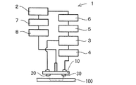
次に、適宜添付図面を参照しながら、本発明をさらに詳しく説明する。図1は本発明に係る超音波試験装置1を示し、この超音波試験装置1は、パーソナルコンピュータ(以下PCと略す)2により制御される板波送受信機3を用いてスキャンヘッド10の送信子20から超音波を送信し、受信子30を介して受信された超音波をプリアンプ4、フィルタ5、A/D変換機6を介してPC2にて受信し、演算処理を行う。またPC2はスキャナードライバ7を介してスキャナ8を起動させ、スキャンヘッド10により、試験体100の探傷を行う。本実施形態では試験体100としてCFRP(Carbon Fiber Reinforced Plastics、炭素繊維強化樹脂)を使用しており、図7に示すように、受信信号はまず音速の速い試験体中伝播波が受信され、その後に空気中伝播波が受信される。図7(a)の健全部に比較して、図7(b)の剥離欠陥部では試験体中伝播波の受信信号が小さくなる。
Next, the present invention will be described in more detail with reference to the accompanying drawings as appropriate. FIG. 1 shows an
図2は、送信子20の部分拡大図である。図2に示すように、送信子20は振動子40として湾曲した焦点型探触子を用いている。振動子40の曲面は球面、楕円円弧回転面又は多角形的な面等、3次的に湾曲しており、湾曲の一方の方向(超音波の伝搬経路の第一揺動方向軸)L1を焦点Pの近傍の伝搬部の試験体100の表面を含む伝搬部表面L2と交差させている。図示しないが、受信子30も同様に、第一揺動方向軸L1を伝搬部表面L2と交差させている。
FIG. 2 is a partially enlarged view of the
図3(a)は送信子20のA方向断面図、図3(b)は受信子30のA方向断面図である。図3(a)、(b)で示すように、本発明における送信子20、受信子30は共に、超音波の伝搬経路に沿った基準軸Qを探触子の焦点Pを中心に揺動させる方向に沿った第一揺動軸L1を伝搬部表面L2と交差させるだけでなく、先の軸L1に直交する湾曲の他方の方向軸(焦点Pを中心とする第二揺動方向軸)L3が超音波伝搬部の試験体100表面を含む伝搬部表面L2と平行となるように送信子20、及び受信子30を構成する振動子40を配向させている。
3A is a cross-sectional view of the
図4は、試験体100の材質、各板波のモード(符号A0〜5、S0〜7)についての超音波の周波数と試験体の厚さとの積と、入射角度との関係を示すグラフである。このような関係を満たす場合のみ、特定のモードの板波が発生する。本発明においては、送信子20、及び受信子30を構成する振動子40に湾曲した焦点型探触子を用いて、第一揺動方向軸L1を伝搬部表面L2と交差させている。これにより、図2の矢印で示すように入射角θ(及び受信可能角)がθ=θ0を基準として複数状態(θ1〜θ2)をとりうる。
FIG. 4 is a graph showing the relationship between the incident angle and the product of the
よって、図4に示すように、符号S1のモードを例にとると、入射角θがθ1〜θ2の範囲に対応する周波数×板厚FT1〜FT2に関して、板波Wとしての超音波の伝搬が可能となる。また、入射角θがθ1〜θ2の範囲に対し、対応モードの異なる波、例えばS0モードなら周波数×板厚FTa1〜FTa2、S2モードなら周波数×板厚FTb1〜FTb2に関して、板波Wとしての超音波の伝搬が可能となる。さらに、入射角θと周波数×板厚FTとのそれぞれの範囲関係によっては、複数モードの板波を同時に試験体100に発生させることが可能となる。なお、第二変更方向軸L3が伝搬部表面L2と平行となるように、送信子20、受信子30の振動子40を配向させることにより、超音波の焦点Pを試験体100上で拡散させずに絞り込んで送受信強度を向上させることが可能となる。
Therefore, as shown in FIG. 4, taking the mode of
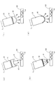
また、送信子20の形状は上記の構成の焦点型探触子に限定されない。例えば、図5(a)に示すように、平面振動子41を用いて、送信子20からの放出面に、凹型音響レンズ43を設けて焦点型探触子を構成してもよい。
Further, the shape of the
また、図5(b)に示すように、センサアレイ振動子42を採用しても良い。この線状(又は面状)に配置された複数の振動子を、時間差で振動させることにより、超音波の焦点Pを試験体100の表面に合致させてもよい。
Further, as shown in FIG. 5B, a
更には、図5(c)に示すように、平面振動子41を用いて、送信子20からの放出面に、凸型音響レンズ44を設け、又は、図5(d)の如く凸型振動子45を用いて、送信子20から超音波を拡散させることにより、入射角θを複数得てもよい。但し、音圧の確保という点からは焦点型のものが望ましい。
Further, as shown in FIG. 5C, a convex
上記、本発明に係る実施の形態では、送信子20と受信子30における振動子40を同じ形式である手段を採用した。しかし、図2、図5の如き構成は入射角等θ及びFTの値が一定の場合は不要であり、送信子20、受信子30のいずれか一方のみを従来型の一方向に超音波を送受信する探触子としてもよい。
In the above-described embodiment according to the present invention, means in which the
本発明によれば、試験体100の板厚が一定に変化するものだけに対応できるだけではない。例えば図6(a)のようにスキャンヘッド10をD方向に走査させた場合、ある箇所で板厚がT4からT5に一定に変化した場合だけではなく、図6(b)に示すように、試験体100の表面が荒れて入射角θが変動する場合や、図6(c)に示すように、試験体100の表面が大きく変動しθ及びFTの双方が変動する場合においても、板波を発生させることが可能である。また、図6(d)に示すように種類の異なる材料100a,100bを超音波伝播経路で切替接合してなる試験体100についても、超音波の送受信が可能となる。これにより、航空機等に用いられている厚さ・材質が種々変化するCFRP材等の内部の欠陥を検出することが可能となる。なお、本発明は、探触子と板波を伝搬する試験体との間で空気のみならずあらゆる気体を介して超音波を伝搬させて試験体を試験する超音波試験方法及びこれを用いた超音波試験装置に適用することができる。
According to the present invention, it is not only possible to deal only with the
本発明は、送信子又は受信子を問わず探触子と試験体との間で板波を発生させる超音波を伝搬させて試験体を試験する超音波試験方法及びこれを用いた超音波試験装置として用いることができる。本発明に係る試験装置の適用対象となる試験体は種類を問わず、非接触で媒質を要しないことから、例えば、航空機材料等としてのCFRP等の検査に用いることも可能である。
The present invention relates to an ultrasonic test method for testing a test body by propagating an ultrasonic wave that generates a plate wave between a probe and a test body regardless of a transmitter or a receiver, and an ultrasonic test using the same. It can be used as a device. The test object to which the test apparatus according to the present invention is applied is not contacted and does not require a medium, so that it can be used for, for example, inspection of CFRP as an aircraft material or the like.
1:超音波試験装置、2:PC、3:板波送受信機、4:プリアンプ、5:フィルタ、6:A/D変換機、7:スキャナードライバ、8:スキャナ、10:スキャンヘッド、20:送信子、30:受信子、40:振動子(凹型)、41:平面振動子、42:センサアレイ振動子、43:凹型音響レンズ、44:凸型音響レンズ、45:振動子(凸型)、100:試験体(CFRP)、100a、b:種類の異なる試験体材料、W:板波、L1:第一揺動方向軸、L2:伝搬部表面、L3:第二揺動方向軸、P:焦点、θ:入射角、F:周波数、T:板厚、D:走査方向
1: Ultrasonic test apparatus, 2: PC, 3: Plate wave transceiver, 4: Preamplifier, 5: Filter, 6: A / D converter, 7: Scanner driver, 8: Scanner, 10: Scan head, 20: Transmitter, 30: receiver, 40: vibrator (concave), 41: planar vibrator, 42: sensor array vibrator, 43: concave acoustic lens, 44: convex acoustic lens, 45: vibrator (convex) , 100: Specimen (CFRP), 100a, b: Different types of specimen materials, W: Plate wave, L1: First oscillation direction axis, L2: Propagation surface, L3: Second oscillation direction axis, P : Focus, θ: incident angle, F: frequency, T: plate thickness, D: scanning direction
Claims (5)
前記探触子は焦点型探触子であると共にこの探触子から試験体への超音波の入射角又は/及び試験体から探触子への超音波の受信可能角が同時に複数状態をとりうるものであり、超音波の伝搬経路に沿った基準軸を前記探触子の焦点を中心に揺動させる方向である揺動方向軸を超音波伝搬部の試験体表面を含む伝搬部表面と交差させるように前記探触子を配向してあり、前記探触子から超音波を送信し、超音波の入射位置における超音波の周波数と試験体の板厚との積に対応し前記試験体の材質毎に定まる入射角の超音波により特定のモードの板波を発生させ、この板波は前記試験体を伝搬し、伝搬した前記板波において、超音波の出射位置における超音波の周波数と試験体の板厚との積に対応し試験体の材質毎に定まる出射角の超音波を前記探触子により受信する超音波試験方法。 An ultrasonic test method for testing an ultrasonic wave by propagating an ultrasonic wave between a probe that transmits or receives ultrasonic waves and a test body that propagates a plate wave,
The probe is a focus-type probe, and the incident angle of the ultrasonic wave from the probe to the test body and / or the receivable angle of the ultrasonic wave from the test body to the probe can have a plurality of states at the same time. The oscillation direction axis, which is the direction in which the reference axis along the ultrasound propagation path is caused to oscillate around the focal point of the probe, and the propagation portion surface including the test body surface of the ultrasound propagation portion; The probe is oriented so as to intersect, the ultrasonic wave is transmitted from the probe, and the test body corresponds to the product of the frequency of the ultrasonic wave at the ultrasonic incident position and the plate thickness of the test body A plate wave of a specific mode is generated by an ultrasonic wave having an incident angle determined for each material of the material, and this plate wave propagates through the test body, and in the propagated plate wave, the frequency of the ultrasonic wave at the ultrasonic emission position and Corresponding to the product of the thickness of the specimen, the ultrasonic wave with the emission angle determined for each specimen material Ultrasonic testing method for receiving a probe.
前記探触子は焦点型探触子であると共にこの探触子から試験体への超音波の入射角又は/及び試験体から探触子への超音波の受信可能角が同時に複数状態をとりうるものであり、超音波の伝搬経路に沿った基準軸を前記探触子の焦点を中心に揺動させる方向である揺動方向軸を超音波伝搬部の試験体表面を含む伝搬部表面と交差させるように前記探触子を配向してあり、前記探触子から超音波を送信し、超音波の入射位置における超音波の周波数と試験体の板厚との積に対応し前記試験体の材質毎に定まる入射角の超音波により特定のモードの板波を発生させ、この板波は前記試験体を伝搬し、伝搬した前記板波において、超音波の出射位置における超音波の周波数と試験体の板厚との積に対応し試験体の材質毎に定まる出射角の超音波を前記探触子により受信する超音波試験装置。 An ultrasonic test apparatus for testing an ultrasonic wave by propagating an ultrasonic wave between a probe that transmits or receives ultrasonic waves and a test body that propagates a plate wave,
The probe is a focus-type probe, and the incident angle of the ultrasonic wave from the probe to the test body and / or the receivable angle of the ultrasonic wave from the test body to the probe can have a plurality of states at the same time. The oscillation direction axis, which is the direction in which the reference axis along the ultrasound propagation path is caused to oscillate around the focal point of the probe, and the propagation portion surface including the test body surface of the ultrasound propagation portion; The probe is oriented so as to intersect, the ultrasonic wave is transmitted from the probe, and the test body corresponds to the product of the frequency of the ultrasonic wave at the ultrasonic incident position and the plate thickness of the test body A plate wave of a specific mode is generated by an ultrasonic wave having an incident angle determined for each material of the material, and this plate wave propagates through the test body, and in the propagated plate wave, the frequency of the ultrasonic wave at the ultrasonic emission position and Corresponding to the product of the thickness of the specimen, the ultrasonic wave with the emission angle determined for each specimen material Ultrasonic testing device for receiving the probe.
Priority Applications (3)
| Application Number | Priority Date | Filing Date | Title |
|---|---|---|---|
| JP2005195598A JP4120969B2 (en) | 2005-07-04 | 2005-07-04 | Ultrasonic test method and ultrasonic test apparatus using the same |
| US11/988,304 US8225668B2 (en) | 2005-07-04 | 2006-06-30 | Ultrasonic wave testing method and ultrasonic testing device using this method |
| PCT/JP2006/313117 WO2007004571A1 (en) | 2005-07-04 | 2006-06-30 | Ultrasonic wave propagating method and ultrasonic propagating device and ultrasonic testing device using this method |
Applications Claiming Priority (1)
| Application Number | Priority Date | Filing Date | Title |
|---|---|---|---|
| JP2005195598A JP4120969B2 (en) | 2005-07-04 | 2005-07-04 | Ultrasonic test method and ultrasonic test apparatus using the same |
Publications (3)
| Publication Number | Publication Date |
|---|---|
| JP2007010637A JP2007010637A (en) | 2007-01-18 |
| JP2007010637A5 JP2007010637A5 (en) | 2007-12-20 |
| JP4120969B2 true JP4120969B2 (en) | 2008-07-16 |
Family
ID=37604436
Family Applications (1)
| Application Number | Title | Priority Date | Filing Date |
|---|---|---|---|
| JP2005195598A Active JP4120969B2 (en) | 2005-07-04 | 2005-07-04 | Ultrasonic test method and ultrasonic test apparatus using the same |
Country Status (3)
| Country | Link |
|---|---|
| US (1) | US8225668B2 (en) |
| JP (1) | JP4120969B2 (en) |
| WO (1) | WO2007004571A1 (en) |
Families Citing this family (14)
| Publication number | Priority date | Publication date | Assignee | Title |
|---|---|---|---|---|
| PT1889198E (en) | 2005-04-28 | 2015-03-06 | Proteus Digital Health Inc | Pharma-informatics system |
| JP4092704B2 (en) * | 2005-07-04 | 2008-05-28 | 独立行政法人 宇宙航空研究開発機構 | Ultrasonic test method and ultrasonic test apparatus using the same |
| JP2009097942A (en) * | 2007-10-16 | 2009-05-07 | Ihi Aerospace Co Ltd | Noncontact-type array probe, and ultrasonic flaw detection apparatus and method using same |
| DE102007056848B4 (en) | 2007-11-26 | 2018-10-11 | GM Global Technology Operations LLC (n. d. Ges. d. Staates Delaware) | Side airbag system, backrest and headrest |
| JP5205112B2 (en) * | 2008-04-04 | 2013-06-05 | 芦森工業株式会社 | Curing state inspection method of lining material and rehabilitation method of sewer pipe |
| JP4686648B1 (en) * | 2010-09-02 | 2011-05-25 | 株式会社日立製作所 | Ultrasonic inspection method |
| CN102183582B (en) * | 2011-01-27 | 2013-05-29 | 中国商用飞机有限责任公司 | Ultrasonic nondestructive testing device and method |
| DE102011018954B4 (en) * | 2011-04-29 | 2017-12-14 | Fraunhofer-Gesellschaft zur Förderung der angewandten Forschung e.V. | Ultrasonic test head and method for non-destructive testing of a flat test specimen |
| JP5904331B2 (en) * | 2012-07-04 | 2016-04-13 | 三菱電機株式会社 | Array flaw detection apparatus and method |
| JP5642248B2 (en) * | 2013-02-14 | 2014-12-17 | 株式会社神戸製鋼所 | Ultrasonic probe |
| JP6109431B1 (en) * | 2016-03-01 | 2017-04-05 | 三菱電機株式会社 | Ultrasonic measuring apparatus and ultrasonic measuring method |
| DE102016122230B4 (en) * | 2016-11-18 | 2023-08-31 | NDT Global Corporate Ltd. Ireland | Method and device for testing an object for defects |
| US10801836B2 (en) * | 2017-06-13 | 2020-10-13 | The Boeing Company | Composite parts that facilitate ultrasonic imaging of layer boundaries |
| JP7236893B2 (en) * | 2019-03-20 | 2023-03-10 | 三菱電機株式会社 | Liquid detection method and liquid detection device |
Family Cites Families (20)
| Publication number | Priority date | Publication date | Assignee | Title |
|---|---|---|---|---|
| US3165922A (en) * | 1962-04-16 | 1965-01-19 | Daniel C Worlton | Method of applying lamb waves in ultrasonic testing |
| US3512400A (en) * | 1967-04-13 | 1970-05-19 | Panametrics | Ultrasonic testing method |
| JPS58178252A (en) | 1982-04-14 | 1983-10-19 | Nippon Kokan Kk <Nkk> | Ultrasonic probe |
| JPS6070063U (en) * | 1983-10-19 | 1985-05-17 | 株式会社トキメック | Ultrasonic flaw detection equipment |
| JPS61256255A (en) | 1985-05-10 | 1986-11-13 | Hitachi Ltd | Ultrasonic flaw detection apparatus |
| JPS62209356A (en) * | 1986-03-07 | 1987-09-14 | Mitsubishi Electric Corp | Panel wave flaw detection apparatus |
| US4674334A (en) * | 1986-05-13 | 1987-06-23 | The United States Of America As Represented By The Secretary Of The Air Force | Properties of composite laminates using leaky lamb waves |
| USH924H (en) * | 1987-02-24 | 1991-06-04 | The United States Of America As Represented By The Secretary Of The Air Force | Signal analysis in leaky lamb wave nde technique |
| JPH0245454U (en) | 1988-09-24 | 1990-03-28 | ||
| JPH04256852A (en) * | 1991-02-08 | 1992-09-11 | Sumitomo Metal Ind Ltd | Ultrasonic flaw detecting method for thin plate |
| JPH05168094A (en) | 1991-12-19 | 1993-07-02 | Hitachi Ltd | Ultrasonic probe |
| JPH10239286A (en) * | 1997-02-24 | 1998-09-11 | Hitachi Ltd | Device for inspecting surface in water |
| US6067840A (en) | 1997-08-04 | 2000-05-30 | Texas Instruments Incorporated | Method and apparatus for infrared sensing of gas |
| JPH1164309A (en) * | 1997-08-26 | 1999-03-05 | Kobe Steel Ltd | Method and apparatus for measuring material characteristic of roll material |
| JPH11118771A (en) * | 1997-10-20 | 1999-04-30 | Nkk Corp | Ultrasonic flaw-detecting method and device of thin plate with plate-thickness change |
| US6092421A (en) * | 1998-08-28 | 2000-07-25 | California Institute Of Technology | Ultrasonic system for automatic determination of material stiffness constants |
| JP2001221784A (en) * | 2000-02-08 | 2001-08-17 | Japan Steel Works Ltd:The | Ultrasonic skew angle probe |
| JP2004340809A (en) | 2003-05-16 | 2004-12-02 | Mitsubishi Heavy Ind Ltd | Phased array probe and ultrasonic test equipment using it |
| JP3749929B2 (en) | 2003-08-05 | 2006-03-01 | 独立行政法人 宇宙航空研究開発機構 | Ultrasonic inspection apparatus and inspection method using the same |
| JP2005134192A (en) * | 2003-10-29 | 2005-05-26 | Mitsubishi Chemicals Corp | Method for measuring thickness of layer attached to inner surface of tubular body |
-
2005
- 2005-07-04 JP JP2005195598A patent/JP4120969B2/en active Active
-
2006
- 2006-06-30 US US11/988,304 patent/US8225668B2/en not_active Expired - Fee Related
- 2006-06-30 WO PCT/JP2006/313117 patent/WO2007004571A1/en active Application Filing
Also Published As
| Publication number | Publication date |
|---|---|
| JP2007010637A (en) | 2007-01-18 |
| US20090165561A1 (en) | 2009-07-02 |
| WO2007004571A1 (en) | 2007-01-11 |
| US8225668B2 (en) | 2012-07-24 |
Similar Documents
| Publication | Publication Date | Title |
|---|---|---|
| JP4120969B2 (en) | Ultrasonic test method and ultrasonic test apparatus using the same | |
| JP4092704B2 (en) | Ultrasonic test method and ultrasonic test apparatus using the same | |
| JP4544240B2 (en) | Tubular ultrasonic inspection apparatus and ultrasonic inspection method | |
| JP4630992B2 (en) | Ultrasonic inspection method and ultrasonic inspection apparatus used therefor | |
| JPWO2007113907A1 (en) | Ultrasonic probe, ultrasonic flaw detection method and ultrasonic flaw detection apparatus | |
| JP2007078692A (en) | Uni-index variable angle phased array probe | |
| JP5986709B2 (en) | Ultrasonic flaw detection apparatus and ultrasonic flaw detection method | |
| JP2004340809A (en) | Phased array probe and ultrasonic test equipment using it | |
| JP3864180B2 (en) | Ultrasonic test method and ultrasonic test apparatus used therefor | |
| JP5574731B2 (en) | Ultrasonic flaw detection test method | |
| WO2019111381A1 (en) | Ultrasonic flaw detection device | |
| JP2005351718A (en) | Omnidirectional flaw detection probe | |
| JP2008051557A (en) | Ultrasonic probe and ultrasonic flaw detector | |
| JP2002062281A (en) | Flaw depth measuring method and its device | |
| JP2010025817A (en) | Tube ultrasonic flaw detector by non-contact airborne-ultrasonic wave and method therefor | |
| JP2018100852A (en) | Ultrasonic inspection device, ultrasonic inspection method and joint block material manufacturing method | |
| US20060144146A1 (en) | Non-destructive testing of materials | |
| JP2013120082A (en) | Ultrasonic flaw detection method | |
| JP7006444B2 (en) | Ultrasonic flaw detection method | |
| WO2018147036A1 (en) | Ultrasound probe | |
| JP2000131297A (en) | Leakage elastic surface wave measuring probe | |
| JPH022924A (en) | Ultrasonic wave flaw detecting apparatus for seam welded pipe | |
| JP6703832B2 (en) | Ultrasonic flaw detector, ultrasonic flaw detection method and program | |
| JP4835341B2 (en) | Ultrasonic flaw detection method | |
| JP5709357B2 (en) | Ultrasonic flaw detection apparatus and ultrasonic flaw detection method |
Legal Events
| Date | Code | Title | Description |
|---|---|---|---|
| A621 | Written request for application examination |
Free format text: JAPANESE INTERMEDIATE CODE: A621 Effective date: 20050726 |
|
| A521 | Request for written amendment filed |
Free format text: JAPANESE INTERMEDIATE CODE: A523 Effective date: 20050726 Free format text: JAPANESE INTERMEDIATE CODE: A821 Effective date: 20050726 |
|
| A521 | Request for written amendment filed |
Free format text: JAPANESE INTERMEDIATE CODE: A523 Effective date: 20051026 |
|
| A521 | Request for written amendment filed |
Free format text: JAPANESE INTERMEDIATE CODE: A523 Effective date: 20060207 |
|
| A521 | Request for written amendment filed |
Free format text: JAPANESE INTERMEDIATE CODE: A523 Effective date: 20071101 |
|
| A871 | Explanation of circumstances concerning accelerated examination |
Free format text: JAPANESE INTERMEDIATE CODE: A871 Effective date: 20071101 |
|
| A975 | Report on accelerated examination |
Free format text: JAPANESE INTERMEDIATE CODE: A971005 Effective date: 20071121 |
|
| A131 | Notification of reasons for refusal |
Free format text: JAPANESE INTERMEDIATE CODE: A131 Effective date: 20071205 |
|
| A521 | Request for written amendment filed |
Free format text: JAPANESE INTERMEDIATE CODE: A523 Effective date: 20080124 |
|
| A131 | Notification of reasons for refusal |
Free format text: JAPANESE INTERMEDIATE CODE: A131 Effective date: 20080219 |
|
| A521 | Request for written amendment filed |
Free format text: JAPANESE INTERMEDIATE CODE: A523 Effective date: 20080227 |
|
| TRDD | Decision of grant or rejection written | ||
| A01 | Written decision to grant a patent or to grant a registration (utility model) |
Free format text: JAPANESE INTERMEDIATE CODE: A01 Effective date: 20080415 |
|
| A61 | First payment of annual fees (during grant procedure) |
Free format text: JAPANESE INTERMEDIATE CODE: A61 Effective date: 20080421 |
|
| FPAY | Renewal fee payment (event date is renewal date of database) |
Free format text: PAYMENT UNTIL: 20110509 Year of fee payment: 3 |
|
| R150 | Certificate of patent or registration of utility model |
Ref document number: 4120969 Country of ref document: JP Free format text: JAPANESE INTERMEDIATE CODE: R150 Free format text: JAPANESE INTERMEDIATE CODE: R150 |
|
| FPAY | Renewal fee payment (event date is renewal date of database) |
Free format text: PAYMENT UNTIL: 20110509 Year of fee payment: 3 |
|
| FPAY | Renewal fee payment (event date is renewal date of database) |
Free format text: PAYMENT UNTIL: 20120509 Year of fee payment: 4 |
|
| R250 | Receipt of annual fees |
Free format text: JAPANESE INTERMEDIATE CODE: R250 |
|
| FPAY | Renewal fee payment (event date is renewal date of database) |
Free format text: PAYMENT UNTIL: 20120509 Year of fee payment: 4 |
|
| FPAY | Renewal fee payment (event date is renewal date of database) |
Free format text: PAYMENT UNTIL: 20130509 Year of fee payment: 5 |
|
| R250 | Receipt of annual fees |
Free format text: JAPANESE INTERMEDIATE CODE: R250 |
|
| FPAY | Renewal fee payment (event date is renewal date of database) |
Free format text: PAYMENT UNTIL: 20130509 Year of fee payment: 5 |
|
| FPAY | Renewal fee payment (event date is renewal date of database) |
Free format text: PAYMENT UNTIL: 20130509 Year of fee payment: 5 |
|
| FPAY | Renewal fee payment (event date is renewal date of database) |
Free format text: PAYMENT UNTIL: 20140509 Year of fee payment: 6 |
|
| R250 | Receipt of annual fees |
Free format text: JAPANESE INTERMEDIATE CODE: R250 |
|
| R250 | Receipt of annual fees |
Free format text: JAPANESE INTERMEDIATE CODE: R250 |
|
| R250 | Receipt of annual fees |
Free format text: JAPANESE INTERMEDIATE CODE: R250 |
|
| S533 | Written request for registration of change of name |
Free format text: JAPANESE INTERMEDIATE CODE: R313533 |
|
| R350 | Written notification of registration of transfer |
Free format text: JAPANESE INTERMEDIATE CODE: R350 |
|
| R250 | Receipt of annual fees |
Free format text: JAPANESE INTERMEDIATE CODE: R250 |
|
| R250 | Receipt of annual fees |
Free format text: JAPANESE INTERMEDIATE CODE: R250 |
|
| R250 | Receipt of annual fees |
Free format text: JAPANESE INTERMEDIATE CODE: R250 |
|
| R250 | Receipt of annual fees |
Free format text: JAPANESE INTERMEDIATE CODE: R250 |
|
| R250 | Receipt of annual fees |
Free format text: JAPANESE INTERMEDIATE CODE: R250 |
|
| R250 | Receipt of annual fees |
Free format text: JAPANESE INTERMEDIATE CODE: R250 |
|
| R250 | Receipt of annual fees |
Free format text: JAPANESE INTERMEDIATE CODE: R250 |
|
| R250 | Receipt of annual fees |
Free format text: JAPANESE INTERMEDIATE CODE: R250 |
|
| R250 | Receipt of annual fees |
Free format text: JAPANESE INTERMEDIATE CODE: R250 |