JP4118516B2 - Modular knee implant system - Google Patents
Modular knee implant system Download PDFInfo
- Publication number
- JP4118516B2 JP4118516B2 JP2000568427A JP2000568427A JP4118516B2 JP 4118516 B2 JP4118516 B2 JP 4118516B2 JP 2000568427 A JP2000568427 A JP 2000568427A JP 2000568427 A JP2000568427 A JP 2000568427A JP 4118516 B2 JP4118516 B2 JP 4118516B2
- Authority
- JP
- Japan
- Prior art keywords
- implant
- pulley
- knee
- patella
- femoral
- Prior art date
- Legal status (The legal status is an assumption and is not a legal conclusion. Google has not performed a legal analysis and makes no representation as to the accuracy of the status listed.)
- Expired - Fee Related
Links
Images


Classifications
-
- A—HUMAN NECESSITIES
- A61—MEDICAL OR VETERINARY SCIENCE; HYGIENE
- A61F—FILTERS IMPLANTABLE INTO BLOOD VESSELS; PROSTHESES; DEVICES PROVIDING PATENCY TO, OR PREVENTING COLLAPSING OF, TUBULAR STRUCTURES OF THE BODY, e.g. STENTS; ORTHOPAEDIC, NURSING OR CONTRACEPTIVE DEVICES; FOMENTATION; TREATMENT OR PROTECTION OF EYES OR EARS; BANDAGES, DRESSINGS OR ABSORBENT PADS; FIRST-AID KITS
- A61F2/00—Filters implantable into blood vessels; Prostheses, i.e. artificial substitutes or replacements for parts of the body; Appliances for connecting them with the body; Devices providing patency to, or preventing collapsing of, tubular structures of the body, e.g. stents
- A61F2/02—Prostheses implantable into the body
- A61F2/30—Joints
- A61F2/38—Joints for elbows or knees
-
- A—HUMAN NECESSITIES
- A61—MEDICAL OR VETERINARY SCIENCE; HYGIENE
- A61F—FILTERS IMPLANTABLE INTO BLOOD VESSELS; PROSTHESES; DEVICES PROVIDING PATENCY TO, OR PREVENTING COLLAPSING OF, TUBULAR STRUCTURES OF THE BODY, e.g. STENTS; ORTHOPAEDIC, NURSING OR CONTRACEPTIVE DEVICES; FOMENTATION; TREATMENT OR PROTECTION OF EYES OR EARS; BANDAGES, DRESSINGS OR ABSORBENT PADS; FIRST-AID KITS
- A61F2/00—Filters implantable into blood vessels; Prostheses, i.e. artificial substitutes or replacements for parts of the body; Appliances for connecting them with the body; Devices providing patency to, or preventing collapsing of, tubular structures of the body, e.g. stents
- A61F2/02—Prostheses implantable into the body
- A61F2/30—Joints
- A61F2/30767—Special external or bone-contacting surface, e.g. coating for improving bone ingrowth
-
- A—HUMAN NECESSITIES
- A61—MEDICAL OR VETERINARY SCIENCE; HYGIENE
- A61F—FILTERS IMPLANTABLE INTO BLOOD VESSELS; PROSTHESES; DEVICES PROVIDING PATENCY TO, OR PREVENTING COLLAPSING OF, TUBULAR STRUCTURES OF THE BODY, e.g. STENTS; ORTHOPAEDIC, NURSING OR CONTRACEPTIVE DEVICES; FOMENTATION; TREATMENT OR PROTECTION OF EYES OR EARS; BANDAGES, DRESSINGS OR ABSORBENT PADS; FIRST-AID KITS
- A61F2/00—Filters implantable into blood vessels; Prostheses, i.e. artificial substitutes or replacements for parts of the body; Appliances for connecting them with the body; Devices providing patency to, or preventing collapsing of, tubular structures of the body, e.g. stents
- A61F2/02—Prostheses implantable into the body
- A61F2/30—Joints
- A61F2/38—Joints for elbows or knees
- A61F2/3859—Femoral components
-
- A—HUMAN NECESSITIES
- A61—MEDICAL OR VETERINARY SCIENCE; HYGIENE
- A61F—FILTERS IMPLANTABLE INTO BLOOD VESSELS; PROSTHESES; DEVICES PROVIDING PATENCY TO, OR PREVENTING COLLAPSING OF, TUBULAR STRUCTURES OF THE BODY, e.g. STENTS; ORTHOPAEDIC, NURSING OR CONTRACEPTIVE DEVICES; FOMENTATION; TREATMENT OR PROTECTION OF EYES OR EARS; BANDAGES, DRESSINGS OR ABSORBENT PADS; FIRST-AID KITS
- A61F2/00—Filters implantable into blood vessels; Prostheses, i.e. artificial substitutes or replacements for parts of the body; Appliances for connecting them with the body; Devices providing patency to, or preventing collapsing of, tubular structures of the body, e.g. stents
- A61F2/02—Prostheses implantable into the body
- A61F2/30—Joints
- A61F2/38—Joints for elbows or knees
- A61F2/3877—Patellae or trochleae
-
- A—HUMAN NECESSITIES
- A61—MEDICAL OR VETERINARY SCIENCE; HYGIENE
- A61F—FILTERS IMPLANTABLE INTO BLOOD VESSELS; PROSTHESES; DEVICES PROVIDING PATENCY TO, OR PREVENTING COLLAPSING OF, TUBULAR STRUCTURES OF THE BODY, e.g. STENTS; ORTHOPAEDIC, NURSING OR CONTRACEPTIVE DEVICES; FOMENTATION; TREATMENT OR PROTECTION OF EYES OR EARS; BANDAGES, DRESSINGS OR ABSORBENT PADS; FIRST-AID KITS
- A61F2/00—Filters implantable into blood vessels; Prostheses, i.e. artificial substitutes or replacements for parts of the body; Appliances for connecting them with the body; Devices providing patency to, or preventing collapsing of, tubular structures of the body, e.g. stents
- A61F2/02—Prostheses implantable into the body
- A61F2/30—Joints
- A61F2/38—Joints for elbows or knees
- A61F2/389—Tibial components
-
- A—HUMAN NECESSITIES
- A61—MEDICAL OR VETERINARY SCIENCE; HYGIENE
- A61F—FILTERS IMPLANTABLE INTO BLOOD VESSELS; PROSTHESES; DEVICES PROVIDING PATENCY TO, OR PREVENTING COLLAPSING OF, TUBULAR STRUCTURES OF THE BODY, e.g. STENTS; ORTHOPAEDIC, NURSING OR CONTRACEPTIVE DEVICES; FOMENTATION; TREATMENT OR PROTECTION OF EYES OR EARS; BANDAGES, DRESSINGS OR ABSORBENT PADS; FIRST-AID KITS
- A61F2/00—Filters implantable into blood vessels; Prostheses, i.e. artificial substitutes or replacements for parts of the body; Appliances for connecting them with the body; Devices providing patency to, or preventing collapsing of, tubular structures of the body, e.g. stents
- A61F2/02—Prostheses implantable into the body
- A61F2/30—Joints
- A61F2002/30001—Additional features of subject-matter classified in A61F2/28, A61F2/30 and subgroups thereof
- A61F2002/30108—Shapes
- A61F2002/3011—Cross-sections or two-dimensional shapes
- A61F2002/30159—Concave polygonal shapes
- A61F2002/30179—X-shaped
-
- A—HUMAN NECESSITIES
- A61—MEDICAL OR VETERINARY SCIENCE; HYGIENE
- A61F—FILTERS IMPLANTABLE INTO BLOOD VESSELS; PROSTHESES; DEVICES PROVIDING PATENCY TO, OR PREVENTING COLLAPSING OF, TUBULAR STRUCTURES OF THE BODY, e.g. STENTS; ORTHOPAEDIC, NURSING OR CONTRACEPTIVE DEVICES; FOMENTATION; TREATMENT OR PROTECTION OF EYES OR EARS; BANDAGES, DRESSINGS OR ABSORBENT PADS; FIRST-AID KITS
- A61F2/00—Filters implantable into blood vessels; Prostheses, i.e. artificial substitutes or replacements for parts of the body; Appliances for connecting them with the body; Devices providing patency to, or preventing collapsing of, tubular structures of the body, e.g. stents
- A61F2/02—Prostheses implantable into the body
- A61F2/30—Joints
- A61F2002/30001—Additional features of subject-matter classified in A61F2/28, A61F2/30 and subgroups thereof
- A61F2002/30316—The prosthesis having different structural features at different locations within the same prosthesis; Connections between prosthetic parts; Special structural features of bone or joint prostheses not otherwise provided for
- A61F2002/30535—Special structural features of bone or joint prostheses not otherwise provided for
- A61F2002/30604—Special structural features of bone or joint prostheses not otherwise provided for modular
-
- A—HUMAN NECESSITIES
- A61—MEDICAL OR VETERINARY SCIENCE; HYGIENE
- A61F—FILTERS IMPLANTABLE INTO BLOOD VESSELS; PROSTHESES; DEVICES PROVIDING PATENCY TO, OR PREVENTING COLLAPSING OF, TUBULAR STRUCTURES OF THE BODY, e.g. STENTS; ORTHOPAEDIC, NURSING OR CONTRACEPTIVE DEVICES; FOMENTATION; TREATMENT OR PROTECTION OF EYES OR EARS; BANDAGES, DRESSINGS OR ABSORBENT PADS; FIRST-AID KITS
- A61F2/00—Filters implantable into blood vessels; Prostheses, i.e. artificial substitutes or replacements for parts of the body; Appliances for connecting them with the body; Devices providing patency to, or preventing collapsing of, tubular structures of the body, e.g. stents
- A61F2/02—Prostheses implantable into the body
- A61F2/30—Joints
- A61F2002/30001—Additional features of subject-matter classified in A61F2/28, A61F2/30 and subgroups thereof
- A61F2002/30667—Features concerning an interaction with the environment or a particular use of the prosthesis
- A61F2002/30708—Means for distinguishing between left-sided and right-sided devices, Sets comprising both left-sided and right-sided prosthetic parts
-
- A—HUMAN NECESSITIES
- A61—MEDICAL OR VETERINARY SCIENCE; HYGIENE
- A61F—FILTERS IMPLANTABLE INTO BLOOD VESSELS; PROSTHESES; DEVICES PROVIDING PATENCY TO, OR PREVENTING COLLAPSING OF, TUBULAR STRUCTURES OF THE BODY, e.g. STENTS; ORTHOPAEDIC, NURSING OR CONTRACEPTIVE DEVICES; FOMENTATION; TREATMENT OR PROTECTION OF EYES OR EARS; BANDAGES, DRESSINGS OR ABSORBENT PADS; FIRST-AID KITS
- A61F2/00—Filters implantable into blood vessels; Prostheses, i.e. artificial substitutes or replacements for parts of the body; Appliances for connecting them with the body; Devices providing patency to, or preventing collapsing of, tubular structures of the body, e.g. stents
- A61F2/02—Prostheses implantable into the body
- A61F2/30—Joints
- A61F2/30767—Special external or bone-contacting surface, e.g. coating for improving bone ingrowth
- A61F2/30771—Special external or bone-contacting surface, e.g. coating for improving bone ingrowth applied in original prostheses, e.g. holes or grooves
- A61F2002/30878—Special external or bone-contacting surface, e.g. coating for improving bone ingrowth applied in original prostheses, e.g. holes or grooves with non-sharp protrusions, for instance contacting the bone for anchoring, e.g. keels, pegs, pins, posts, shanks, stems, struts
- A61F2002/30891—Plurality of protrusions
- A61F2002/30892—Plurality of protrusions parallel
-
- A—HUMAN NECESSITIES
- A61—MEDICAL OR VETERINARY SCIENCE; HYGIENE
- A61F—FILTERS IMPLANTABLE INTO BLOOD VESSELS; PROSTHESES; DEVICES PROVIDING PATENCY TO, OR PREVENTING COLLAPSING OF, TUBULAR STRUCTURES OF THE BODY, e.g. STENTS; ORTHOPAEDIC, NURSING OR CONTRACEPTIVE DEVICES; FOMENTATION; TREATMENT OR PROTECTION OF EYES OR EARS; BANDAGES, DRESSINGS OR ABSORBENT PADS; FIRST-AID KITS
- A61F2/00—Filters implantable into blood vessels; Prostheses, i.e. artificial substitutes or replacements for parts of the body; Appliances for connecting them with the body; Devices providing patency to, or preventing collapsing of, tubular structures of the body, e.g. stents
- A61F2/02—Prostheses implantable into the body
- A61F2/30—Joints
- A61F2/30767—Special external or bone-contacting surface, e.g. coating for improving bone ingrowth
- A61F2002/30922—Hardened surfaces
-
- A—HUMAN NECESSITIES
- A61—MEDICAL OR VETERINARY SCIENCE; HYGIENE
- A61F—FILTERS IMPLANTABLE INTO BLOOD VESSELS; PROSTHESES; DEVICES PROVIDING PATENCY TO, OR PREVENTING COLLAPSING OF, TUBULAR STRUCTURES OF THE BODY, e.g. STENTS; ORTHOPAEDIC, NURSING OR CONTRACEPTIVE DEVICES; FOMENTATION; TREATMENT OR PROTECTION OF EYES OR EARS; BANDAGES, DRESSINGS OR ABSORBENT PADS; FIRST-AID KITS
- A61F2/00—Filters implantable into blood vessels; Prostheses, i.e. artificial substitutes or replacements for parts of the body; Appliances for connecting them with the body; Devices providing patency to, or preventing collapsing of, tubular structures of the body, e.g. stents
- A61F2/02—Prostheses implantable into the body
- A61F2/30—Joints
- A61F2/46—Special tools or methods for implanting or extracting artificial joints, accessories, bone grafts or substitutes, or particular adaptations therefor
- A61F2002/4631—Special tools or methods for implanting or extracting artificial joints, accessories, bone grafts or substitutes, or particular adaptations therefor the prosthesis being specially adapted for being cemented
-
- A—HUMAN NECESSITIES
- A61—MEDICAL OR VETERINARY SCIENCE; HYGIENE
- A61F—FILTERS IMPLANTABLE INTO BLOOD VESSELS; PROSTHESES; DEVICES PROVIDING PATENCY TO, OR PREVENTING COLLAPSING OF, TUBULAR STRUCTURES OF THE BODY, e.g. STENTS; ORTHOPAEDIC, NURSING OR CONTRACEPTIVE DEVICES; FOMENTATION; TREATMENT OR PROTECTION OF EYES OR EARS; BANDAGES, DRESSINGS OR ABSORBENT PADS; FIRST-AID KITS
- A61F2230/00—Geometry of prostheses classified in groups A61F2/00 - A61F2/26 or A61F2/82 or A61F9/00 or A61F11/00 or subgroups thereof
- A61F2230/0002—Two-dimensional shapes, e.g. cross-sections
- A61F2230/0028—Shapes in the form of latin or greek characters
-
- A—HUMAN NECESSITIES
- A61—MEDICAL OR VETERINARY SCIENCE; HYGIENE
- A61F—FILTERS IMPLANTABLE INTO BLOOD VESSELS; PROSTHESES; DEVICES PROVIDING PATENCY TO, OR PREVENTING COLLAPSING OF, TUBULAR STRUCTURES OF THE BODY, e.g. STENTS; ORTHOPAEDIC, NURSING OR CONTRACEPTIVE DEVICES; FOMENTATION; TREATMENT OR PROTECTION OF EYES OR EARS; BANDAGES, DRESSINGS OR ABSORBENT PADS; FIRST-AID KITS
- A61F2250/00—Special features of prostheses classified in groups A61F2/00 - A61F2/26 or A61F2/82 or A61F9/00 or A61F11/00 or subgroups thereof
- A61F2250/0058—Additional features; Implant or prostheses properties not otherwise provided for
- A61F2250/0084—Means for distinguishing between left-sided and right-sided devices; Sets comprising both left-sided and right-sided prosthetic parts
-
- A—HUMAN NECESSITIES
- A61—MEDICAL OR VETERINARY SCIENCE; HYGIENE
- A61F—FILTERS IMPLANTABLE INTO BLOOD VESSELS; PROSTHESES; DEVICES PROVIDING PATENCY TO, OR PREVENTING COLLAPSING OF, TUBULAR STRUCTURES OF THE BODY, e.g. STENTS; ORTHOPAEDIC, NURSING OR CONTRACEPTIVE DEVICES; FOMENTATION; TREATMENT OR PROTECTION OF EYES OR EARS; BANDAGES, DRESSINGS OR ABSORBENT PADS; FIRST-AID KITS
- A61F2310/00—Prostheses classified in A61F2/28 or A61F2/30 - A61F2/44 being constructed from or coated with a particular material
- A61F2310/00005—The prosthesis being constructed from a particular material
- A61F2310/00011—Metals or alloys
- A61F2310/00017—Iron- or Fe-based alloys, e.g. stainless steel
-
- A—HUMAN NECESSITIES
- A61—MEDICAL OR VETERINARY SCIENCE; HYGIENE
- A61F—FILTERS IMPLANTABLE INTO BLOOD VESSELS; PROSTHESES; DEVICES PROVIDING PATENCY TO, OR PREVENTING COLLAPSING OF, TUBULAR STRUCTURES OF THE BODY, e.g. STENTS; ORTHOPAEDIC, NURSING OR CONTRACEPTIVE DEVICES; FOMENTATION; TREATMENT OR PROTECTION OF EYES OR EARS; BANDAGES, DRESSINGS OR ABSORBENT PADS; FIRST-AID KITS
- A61F2310/00—Prostheses classified in A61F2/28 or A61F2/30 - A61F2/44 being constructed from or coated with a particular material
- A61F2310/00005—The prosthesis being constructed from a particular material
- A61F2310/00011—Metals or alloys
- A61F2310/00023—Titanium or titanium-based alloys, e.g. Ti-Ni alloys
-
- A—HUMAN NECESSITIES
- A61—MEDICAL OR VETERINARY SCIENCE; HYGIENE
- A61F—FILTERS IMPLANTABLE INTO BLOOD VESSELS; PROSTHESES; DEVICES PROVIDING PATENCY TO, OR PREVENTING COLLAPSING OF, TUBULAR STRUCTURES OF THE BODY, e.g. STENTS; ORTHOPAEDIC, NURSING OR CONTRACEPTIVE DEVICES; FOMENTATION; TREATMENT OR PROTECTION OF EYES OR EARS; BANDAGES, DRESSINGS OR ABSORBENT PADS; FIRST-AID KITS
- A61F2310/00—Prostheses classified in A61F2/28 or A61F2/30 - A61F2/44 being constructed from or coated with a particular material
- A61F2310/00005—The prosthesis being constructed from a particular material
- A61F2310/00011—Metals or alloys
- A61F2310/00029—Cobalt-based alloys, e.g. Co-Cr alloys or Vitallium
-
- A—HUMAN NECESSITIES
- A61—MEDICAL OR VETERINARY SCIENCE; HYGIENE
- A61F—FILTERS IMPLANTABLE INTO BLOOD VESSELS; PROSTHESES; DEVICES PROVIDING PATENCY TO, OR PREVENTING COLLAPSING OF, TUBULAR STRUCTURES OF THE BODY, e.g. STENTS; ORTHOPAEDIC, NURSING OR CONTRACEPTIVE DEVICES; FOMENTATION; TREATMENT OR PROTECTION OF EYES OR EARS; BANDAGES, DRESSINGS OR ABSORBENT PADS; FIRST-AID KITS
- A61F2310/00—Prostheses classified in A61F2/28 or A61F2/30 - A61F2/44 being constructed from or coated with a particular material
- A61F2310/00005—The prosthesis being constructed from a particular material
- A61F2310/00179—Ceramics or ceramic-like structures
Landscapes
- Health & Medical Sciences (AREA)
- Orthopedic Medicine & Surgery (AREA)
- Physical Education & Sports Medicine (AREA)
- Cardiology (AREA)
- Oral & Maxillofacial Surgery (AREA)
- Transplantation (AREA)
- Engineering & Computer Science (AREA)
- Biomedical Technology (AREA)
- Heart & Thoracic Surgery (AREA)
- Vascular Medicine (AREA)
- Life Sciences & Earth Sciences (AREA)
- Animal Behavior & Ethology (AREA)
- General Health & Medical Sciences (AREA)
- Public Health (AREA)
- Veterinary Medicine (AREA)
- Prostheses (AREA)
- Orthopedics, Nursing, And Contraception (AREA)
Abstract
Description
【0001】
〔発明の属する技術分野〕
本発明は一般に、人工関節用のモジュール式膝インプラントシステムに関し、特に、滑車インプラントを含むシステムに関する。
【0002】
〔発明の背景〕
膝関節は、3つの骨、即ち大腿骨、脛骨、及び膝蓋骨を互いに連結している。病気、外傷又は不整列に起因する時期尚早な摩耗の何れかにより、膝関節が損傷を受ける場合があり、損傷を受けた関節面を全て又は部分的に人工インプラントで置き換えなければならない場合がある。最も一般的な人工膝プラントは、「人工膝関節全置換術」システムと呼ばれている。というのは、すべての膝関節面を交換するからである。代表的には、人工膝関節全置換術システムは、膝蓋骨インプラント、大腿骨インプラント及び脛骨インプラントを含む。
【0003】
膝の互いに異なる部分は、コンパートメントと呼ばれている。例えば、各関節丘(大腿骨の丸い端部)は、別個のコンパートメントである。「ユニコンパートメンタル」置換システムと呼ばれる他の人工インプラントは、大腿骨−脛骨表面のメディアル(体の中線に向かう方向の)コンパートメント又はラテラル(体の中線から遠ざかる方向の)コンパートメントを交換する必要がある場合にのみ用いることができる。ユニコンパートメンタル置換システムは、大腿骨及び脛骨インプラントを有するが、膝蓋骨インプラントを含まない。現在入手できるユニコンパートメンタルインプラントシステムは、モジュール設計のものであり、同一の器具及び同一の骨輪郭を用いる場合には同一の製造業者からのこれら全膝相当部品と共に使用されるよう設計されている。これらユニコンパートメンタルインプラントシステムを全膝システムで交換する必要のある場合、大腿骨インプラントと脛骨インプラントの両方を取り除く必要がある。
【0004】
膝蓋骨と大腿骨の前に位置する溝相互間の膝関節コンパートメントの表面(滑車)の交換が必要になる場合はそれほどない。膝関節のこの部分に取って代わり、「全膝蓋骨−大腿骨」人工装具又はインプラントと呼ばれる幾つかの人工インプラントが入手できる。代表的には、全膝蓋骨−大腿骨人工装具は、膝蓋骨に取り付けられる膝蓋骨インプラント及び膝蓋骨に接触する大腿骨の少なくとも一部に取って代わる別のインプラントを有している。
【0005】
しかしながら、任意の全膝システムに関してモジュール方式の全膝蓋骨−大腿骨インプラントシステムは存在しない。したがって、もし全膝蓋骨−大腿骨人工装具を移植すると、膝がさらに悪化するので、膝蓋骨−大腿骨インプラントを場合によっては数年後に再手術中に交換しなければならず、この場合、インプラントの膝蓋骨構成部品全体を、たとえこれが良好に機能していても除去する必要がある。人工装具構成部品を取り出して別のものに交換する度に、骨の損傷又は骨の損失が避けられず、それにより、第2回目の移植がいっそう困難になり、成功の度合が低くなる。
【0006】
膝蓋骨−大腿骨人工装具を全人工膝関節で置き換える場合、膝蓋骨インプラントの交換を必要としない人工装具システムが要望されている。特に、大腿骨の滑車溝の表面に取り付けられ、選択された全膝インプラントの構成部品と協働する滑車インプラントが要望されている。
【0007】
〔発明の目的及び概要〕
本発明の主目的は、滑車インプラントを全大腿骨インプラントで置き換える際に膝蓋骨インプラントの置換を必要としない人工装具システムを提供することにある。
【0008】
本発明の別の目的は、選択された前膝インプラントシステムのコンポーネントと協働する滑車インプラントを提供することにある。
【0009】
本発明のより一般的な目的は、移植のために除去される骨の量を減少させる人工関節のための滑車インプラントを提供することにある。
【0010】
本発明のさらに別の目的は、互換性のあるコンポーネントを有するモジュール式関節置換システムを提供することにある。
【0011】
概要を述べると、本発明は、大腿骨インプラント及び膝蓋骨インプラントを有する形式の人工膝を提供する。大腿骨インプラント及び膝蓋骨インプラントは、大腿骨インプラントと膝蓋骨インプラントが相対的に動くと、大腿骨インプラントを膝蓋骨インプラントに摺動自在に係合させる支持面を有している。滑車インプラントが、膝蓋骨インプラントの支持面の一部を摺動自在に受け入れるような形状になった関節面を有する。関節面は、大腿骨インプラントの支持面の一部と形状が実質的に同一であって、膝蓋骨インプラントが大腿骨インプラント及び滑車インプラントと共に使用できるようになっている。
【0012】
本発明は又、人工膝用の滑車インプラントを提供する。滑車インプラントは、大腿骨の膝側端部に取り付けられ、膝蓋骨の後側部分に取り付けられた膝蓋骨インプラントと協働する。膝蓋骨インプラントは、大腿骨の膝の端部にとって代わる大腿骨インプラントを含む人工装具のコンポーネントである。滑車インプラントは、膝蓋骨インプラントの一部を摺動自在に受け入れるような形状になった関節面を有する。関節面は、大腿骨インプラントの表面の一部と形状が実質的に同一であって、膝蓋骨インプラントが大腿骨インプラント及び滑車インプラントと共に使用できるようになっている。
【0013】
さらに、本発明は、人工膝システムを用いる膝置換術を提供する。滑車インプラント及び膝蓋骨インプラントを準備する。膝蓋骨インプラントは、滑車インプラント及び大腿骨インプラントと協働する。滑車インプラントは、膝蓋骨インプラントの一部を摺動自在に受け入れるような形状になった関節面を有する。関節面は、大腿骨インプラントの荷重支持面の一部と形状が実質的に同一である。膝蓋骨インプラントを膝の膝蓋骨内に取り付ける。滑車インプラントを大腿骨の膝側端部の滑車溝内に納める。
【0014】
本発明の内容は、添付の図面と関連して以下の詳細な説明を読むとはっきりと理解されよう。
【0015】
〔好ましい実施形態の詳細な説明〕
図1では、本発明に使用するのが適している人工膝インプラント100が、人の膝102内に取り付けられている。膝102は、大腿骨104、膝蓋骨106及び脛骨108を有している。人工膝100は、大腿骨インプラント110、膝蓋骨インプラント112及び任意的に用いられる脛骨インプラント114を有している。脛骨インプラント114は、脛骨プラットホームコンポーネント116及び脛骨支持コンポーネント118を有している。
【0016】
膝蓋骨インプラント112は、大腿骨インプラント110と嵌まり合うような形状になっている。脛骨インプラント114、特に、脛骨支持コンポーネント118は、大腿骨インプラント110と嵌合するような形状になっている。大腿骨インプラント110は、膝蓋骨インプラント112及び脛骨インプラント114を摺動自在に受け入れるような形状になっている。
【0017】
図2は、図1の取付け状態にある人工膝の側面図であり、膝蓋骨106に筋肉を取り付ける腱120をさらに示している。大腿骨インプラント110及び膝蓋骨インプラント112は、それぞれ支持面122,124を有している。大腿骨インプラントと膝蓋骨インプラントが互いに対して動くと、支持面122,124により、大腿骨インプラント110と膝蓋骨インプラント112は摺動自在に係合する。脛骨インプラント114もまた、支持面126を有し、この支持面126は、大腿骨104と脛骨108が互いに対して動くと、大腿骨の支持面122の別の部分に摺動自在に係合する。
【0018】
図3に示すように、本発明の人工膝システムは、大腿骨インプラント110、膝蓋骨インプラント112及び滑車インプラント130を有している。滑車インプラント130は、膝蓋骨インプラント112の支持面124の一部を摺動自在に受け入れるような形状になった関節面132を有している。膝蓋骨インプラント112は、大腿骨インプラント110と滑車インプラント130の両方の滑車溝を形成する長手方向軸線136と整列する頂点134を有している。
【0019】
本発明の顕著な特徴は、滑車インプラント130の関節面132が大腿骨インプラント110の大腿骨支持面122の一部と形状が実質的に同一であることにある。したがって、膝蓋骨インプラント112は、大腿骨インプラント110と滑車インプラント130の両方に使用することができる。患者の残りの関節面が外科医が滑車インプラント130を大腿骨インプラント110で置き換えることが必要である程度まで悪化すると、患者の膝蓋骨は、それ以上の骨の損失及び外傷を受けない。というのは、既存の膝蓋骨インプラント112は、新しい大腿骨インプラント110と共に使用できるからである。
【0020】
膝人工装具相互の根本的な差異は、関節面又は支持面の性状に見られる。2つの基本的なタイプの関節面、即ち理論的に線又は点接触(不一致接触と呼ばれる)の表面と面接触(一致接触と呼ばれる)の表面がある。一致接触の表面は、人体と非常に良く似ている。
【0021】
好ましい実施形態では、滑車インプラント130の関節面138は、膝蓋骨インプラント112に実質的に一致して係合する形状を有している。変形実施形態では、滑車インプラント130の関節面132は、膝蓋骨インプラント112と実質的に点接触するような形状になっている。別の変形実施形態では、滑車インプラント130の関節面132は、膝蓋骨インプラント112と実質的に線接触するような形状になっている。他の実施形態では、滑車インプラント130の関節面132は、膝蓋骨インプラント112と一致且つ線接触の組合せを生じるような形状になっている。
【0022】
一実施形態では、滑車インプラント130は、右又は左の膝の何れか一方に取り付けることができるよう長手方向軸線136の周りに非対称である。図3では、滑車インプラント130は、右側の膝に取付け可能である。変形実施形態では、滑車インプラント130は、長手方向軸線の周りに対称であり、右の膝でも左の膝でも何れにも取り付けることができる。
【0023】
好ましい実施形態では、大腿骨インプラント110の支持面、膝蓋骨インプラント112の支持面及び滑車インプラント130の関節面は、共通の生成曲線138に整列していて、これによって生成される(図3)。変形例として、滑車インプラント130の関節面は、実質的に球形でドーム状の膝蓋骨インプラント130を受け入れてこれと嵌まり合うような形状になっている。
【0024】
滑車インプラント130を、鋳造コバルト−クロム−モリブデンで作るのがよく、関節面132を研磨する。変形例として、滑車インプラント130は、コバルト−クロム、ステンレス鋼又は他の適当な金属合金で作られる。別の変形実施形態では、滑車インプラント130は、セラミック製である。さらに別の実施形態では、滑車インプラント130は、チタン製である。別の変形実施形態では、表面処理を行うことにより滑車インプラント130の関節面を硬化させると共に(或いは)滑らかにする。特に、チタン製の滑車インプラント130を処理して関節面を硬化させると共に滑らかにする。
【0025】
滑車インプラント130は、人の膝100内の大腿骨104の膝側端部の関節丘142相互間の滑車溝内に取り付けられる(図4)。この実施形態では、滑車インプラント130は、脛骨108又は脛骨インプラントに接触しない。変形実施形態では、滑車インプラント130は、脛骨108又は脛骨インプラントに接触する場合がある。
【0026】
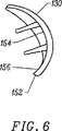
図5、図6及び図7を参照すると、周縁部152が、関節面132及び後面154を構成している。図7においては、後面154は、後面154の一部及び周縁部152の一部に沿って延びるセメント保持リム156を有している。3つの固定ピン158が、後面154から突出している。一実施形態では、後面154には模様が付けられている。変形例として、後面114は、多孔質被膜を有する。変形実施形態では、セメント保持リム156は設けられない。別の変形実施形態では、固定ピンは設けられない。さらに別の変形実施形態では、任意個数、例えば1、2又は4以上の固定ピン158が、後面154から突出する。変形例として、滑車インプラント130は、ねじを用いて大腿骨に固定される。
【0027】
図8及び図9では、本発明の滑車インプラント130は、膝蓋骨インプラント112と共に人の膝の中に位置した状態で示されている。滑車インプラント130は、或る範囲の膝運動が行えるよう膝蓋骨インプラント112に接触する。膝蓋骨インプラント112上の一次及び二次荷重支持領域162,164が、滑車インプラント130の関節領域132の一次及び二次荷重支持領域166,168に係合して実質的に解剖学的膝蓋骨−大腿骨関節部を生じさせる。図9に示すように、脚及び膝の十分な伸長状態では、膝蓋骨インプラント112の一次荷重支持領域162は、滑車インプラント130の一次荷重支持領域166を持ち上げ、膝蓋骨インプラント112の二次荷重支持領域164は、滑車インプラント130の二次荷重支持領域168に摺動自在に係合する。これとは対照的に、適度の且つ十分な曲げ状態では、膝蓋骨インプラント112の一次荷重支持領域162は、滑車インプラント130の一次荷重支持領域166に摺動自在に係合する。
【0028】
変形実施形態では、膝動作の限度のところでは、膝が非常に真っ直ぐであり、又は膝が極端に曲がっている場合、膝蓋骨インプラント112は、滑車インプラント130に接触しない。好ましくは、膝蓋骨インプラント112は、膝がほぼ真直ぐな場合の約20°の角度から膝が曲がっている場合の約110°の角度まで滑車インプラント130に摺動自在に係合する。
【0029】
図10は、本発明の好ましい実施形態における滑車インプラント、大腿骨インプラント、膝蓋骨インプラント及び脛骨インプラントの関節及び荷重支持面の形状を作るのに用いられる共通の生成曲線138を示している。大腿骨、膝蓋骨及び脛骨インプラントの荷重支持面の形成については、タパス氏等に付与された米国特許第4,470,158号に詳細に説明されており、かかる米国特許の内容を本明細書の一部を形成するものとしてここに引用する。
【0030】
関節及び荷重支持面の一次及び二次荷重支持領域は、回転表面として形成され、これらの形状は、共通の生成曲線F138によって構成され又は生成される。荷重支持面又は関節面の形状は、共通の生成曲線F138を同一の長いほうの生成半径D1,D2で生成軸線172の回りに所定の角度回転させることによって生成され、ここでD1,D2は、互いに等しく且つ所定の半径に等しい。共通の生成曲線F138のピーク174は、膝蓋骨インプラントの頂点134(図3)及び大腿骨インプラントと滑車インプラントの長手方向軸線136(図3)を形成する。
【0031】
図11は、本発明の大腿骨インプラント及び滑車インプラントの荷重支持面及び関節面の荷重支持領域のセグメントS1,S2を示している。セグメントS1は、二次荷重支持領域164,168(図9)を形成している。セグメントS2は、膝蓋骨インプラント及び滑車インプラントのそれぞれの一次荷重支持領域162,166(図9)を形成している。
【0032】
特に、滑車インプラントの関節領域を生成するため、共通の生成曲線138を∞のところでの生成軸線C1から半径方向距離のところでθ1(0°に等しい)の角度回転させる。換言すると、共通生成曲線138は、S1、即ち0.314インチ(約7.98mm)の距離を置いて線L1と実質的に平行である。線L1に接した共通生成曲線138を生成軸線C2の回りにR2の距離のところでθ2の角度回転させる。一実施形態では、θ2とR2はそれぞれ約90°、1.388インチ(約約3.53cm)に等しい。滑車インプラントの形状は、線L2のところで終わっている。
【0033】
膝蓋骨インプラント及び大腿骨インプラントの荷重支持領域は類似の方法で生成される。大腿骨インプラントの場合、セグメントS1は、0.612インチ(約15.5mm)の距離をおいてL1と実質的に平行に形成され、セグメントS2は、1.388インチ(約3.53cm)に等しい半径R2で107.75°の角度θ2にわたって形成される。したがって、セグメントS1,S2で形成された滑車インプラントの荷重支持領域148,146(図9)は実質的に、大腿骨インプラントの荷重支持領域S1,S2に実質的にマッチしている。
【0034】
図12を参照すると、滑車インプラント130はテーパしている。滑車インプラント130をテーパさせるために、共通生成曲線138の一部を用い、滑車インプラント130の周囲側縁部176,178を長手方向軸線136に対して所定の角度θ3,θ4のところに形成する。一実施形態では、所定の角度θ3,θ4は、それぞれ実質的に約20°及び30°に等しい。変形実施形態では、θ3とθ4は同一である。
【0035】
図13は、本発明の滑車インプラント182の第2の実施形態を備えた第2の人工膝システム、例えばジョンソン・アンド・ジョンソン社の“PRIMARY CRUCIATE-SUBSTITUTING (P.F.C.)”モジュール式全膝システムを示している。膝蓋骨インプラント184が、大腿骨インプラント186又は滑車インプラント182の何れにも使用することができる。
【0036】
図14は、本発明の滑車インプラント188の第3の実施形態を備えた第3の人工膝システム、例えば、インターメディックス社の“NATURAL-KNEE”を示している。膝蓋骨インプラント190が、大腿骨インプラント192又は滑車インプラント188の何れにも使用することができる。
【0037】
図15は、本発明の滑車インプラント194の第4の実施形態を備えた第4の人工膝システム、例えば、ツィンマー社の“Insall/Burstein(I/B)II”を示している。膝蓋骨インプラント196が、大腿骨インプラント198又は滑車インプラント194の何れにも使用することができる。
【0038】
図16においては、人工膝システムのコンポーネントを用いる膝の置換方法の一実施形態のフローチャートが示されている。ステップ202では、本発明の滑車インプラントを準備し、ステップ204では、本発明に用いるのに適した膝蓋骨インプラントも又準備する。ステップ206では、膝蓋骨インプラントを膝の中の膝蓋骨内に取り付ける。ステップ208では、滑車インプラントを大腿骨の膝側端部の滑車溝内に取り付ける。
【0039】
患者の残りの関節面が、滑車インプラントの交換が必要であるほどに悪化すると、ステップ210において、滑車インプラントに使用するのに適した大腿骨インプラントを準備する。滑車インプラントの関節面の形状と大腿骨インプラントの荷重支持面の形状は実質的に同一である。ステップ212において、滑車インプラントを取り外し、ステップ214において既存の膝蓋骨インプラントを膝蓋骨中の定位置に残しておく。変形実施形態では、膝蓋骨インプラントは、着脱自在な荷重支持面を有しているが、かかる膝蓋骨インプラントであっても、膝蓋骨に取り付けられた膝蓋骨インプラントの部分は、定位置のままである。
【0040】
ステップ216では、外科医は、大腿骨インプラントを大腿骨の膝側端部内に取り付ける。もし膝の脛骨部分の交換の必要がある場合、脛骨インプラントもまた、ステップ218において準備し、ステップ220において取り付ける。
【0041】
かくして、同一の膝蓋骨インプラントを滑車インプラントと大腿骨インプラントの両方に用いることができるようにする人工膝システムが提供されている。したがって、患者の残りの関節面が外科医により滑車インプラントの交換が必要であると判断するほどまでに悪化しても、既存の膝蓋骨インプラントが新品の大腿骨インプラントと共に使用可能なので患者の膝蓋骨はそれ以上の骨の損失及び外傷を生じない。
【0042】
本発明を特定の実施形態を用いて詳細に説明したが、当業者であれば、本発明の精神及び範囲から逸脱することなく種々の形状の滑車プラントを想到できることは明らかであろう。
【図面の簡単な説明】
【図1】 取り付けられた人工膝関節の正面図である。
【図2】 図1の取り付けられた人工膝関節の側面図である。
【図3】 本発明の人工膝インプラントシステムのコンポーネントの分解正面図である。
【図4】 人の膝の中に取り付けられた図3の滑車インプラントの一実施形態の斜視図である。
【図5】 人の膝の中に取り付けられるのに適した本発明の滑車インプラントの一実施形態の斜視図である。
【図6】 図5の滑車インプラントの側面図である。
【図7】 図5の滑車インプラントの底面図である。
【図8】 人の膝の中に取り付けられた図5の滑車インプラントの正面図である。
【図9】 人の膝の中に取り付けられた図5の滑車インプラントの側面図である。
【図10】 図3の滑車インプラントの好ましい実施形態に用いられる共通生成曲線の略図である。
【図11】 滑車インプラントの関節面の形状、大腿骨インプラントの大腿骨荷重支持面の形状及び膝蓋骨インプラントの荷重支持面の形状を定める回転面のセグメントを生成するための図10の共通生成曲線の回転の仕方を示す略図である。
【図12】 周縁部をテーパさせるのに用いられる角度を示す図5の滑車インプラントの底面図である。
【図13】 本発明の滑車インプラントの別の実施形態を用いる第2の人工膝システムの分解図である。
【図14】 本発明の滑車インプラントのさらに別の実施形態を用いる第3の人工膝システムの分解図である。
【図15】 本発明の滑車インプラントのさらに別の実施形態を用いる第4の人工膝システムの分解図である。
【図16】 本発明の人工膝システムのコンポーネントを用いる膝置換術のフローチャートである。[0001]
[Technical field to which the invention belongs]
The present invention relates generally to modular knee implant systems for artificial joints, and more particularly to systems including pulley implants.
[0002]
BACKGROUND OF THE INVENTION
The knee joint connects three bones: the femur, the tibia, and the patella. The knee joint may be damaged due to either premature wear due to illness, trauma or misalignment, and the damaged joint surface may need to be replaced in whole or in part with a prosthetic implant . The most common artificial knee plant is called the “total knee replacement” system. This is because all knee joint surfaces are exchanged. Typically, total knee replacement systems include patella implants, femoral implants, and tibial implants.
[0003]
The different parts of the knee are called compartments. For example, each condyle (rounded end of the femur) is a separate compartment. Other prosthetic implants, called “unicompartmental” replacement systems, replace the femoral-tibia surface medial (in the direction toward the body midline) or lateral (in the direction away from the body midline) compartment Can be used only when necessary. Unicompartmental replacement systems have femoral and tibial implants but do not include patella implants. Currently available Unipartial Implant Systems are of modular design and are designed to be used with these all knee equivalent parts from the same manufacturer when using the same instrument and the same bone contour. . If these Unicompartmental implant systems need to be replaced with a full knee system, both the femoral and tibial implants need to be removed.
[0004]
There is not much need to change the surface of the knee joint compartment (pulley) between the grooves located in front of the patella and femur. There are several prosthetic implants available to replace this part of the knee joint, referred to as “total patella-femur” prostheses or implants. Typically, a total patella-femoral prosthesis has a patella implant attached to the patella and another implant that replaces at least a portion of the femur that contacts the patella.
[0005]
However, there is no modular total patella-femoral implant system for any total knee system. Therefore, if the entire patella-femoral prosthesis is implanted, the knee is further deteriorated, so the patella-femoral implant must be replaced during the reoperation, possibly after several years, in which case the patella of the implant The entire component needs to be removed even if it works well. Each time a prosthetic component is removed and replaced with another, bone damage or bone loss is inevitable, which makes the second implantation more difficult and less successful.
[0006]
When replacing the patella-femoral prosthesis with a total knee prosthesis, there is a need for a prosthetic system that does not require replacement of the patella implant. In particular, there is a need for a pulley implant that attaches to the surface of the femoral pulley groove and cooperates with selected components of the entire knee implant.
[0007]
[Purpose and Summary of the Invention]
It is a primary object of the present invention to provide a prosthetic system that does not require replacement of the patella implant when replacing the pulley implant with a total femoral implant.
[0008]
It is another object of the present invention to provide a pulley implant that cooperates with selected components of an anterior knee implant system.
[0009]
A more general object of the present invention is to provide a pulley implant for an artificial joint that reduces the amount of bone removed for implantation.
[0010]
Yet another object of the present invention is to provide a modular joint replacement system having compatible components.
[0011]
In summary, the present invention provides a type of knee prosthesis having a femoral implant and a patella implant. The femoral implant and the patella implant have a support surface that slidably engages the femoral implant with the patella implant when the femoral implant and the patella implant move relative to each other. The pulley implant has an articulating surface shaped to slidably receive a portion of the support surface of the patella implant. The articular surface is substantially identical in shape to a portion of the support surface of the femoral implant so that the patella implant can be used with the femoral and pulley implants.
[0012]
The present invention also provides a pulley implant for an artificial knee. The pulley implant is attached to the knee end of the femur and cooperates with the patella implant attached to the posterior portion of the patella. A patella implant is a component of a prosthesis that includes a femoral implant that replaces the knee end of the femur. The pulley implant has an articular surface shaped to slidably receive a portion of the patella implant. The articulating surface is substantially identical in shape to a portion of the surface of the femoral implant so that the patella implant can be used with the femoral and pulley implants.
[0013]
The present invention further provides knee replacement using an artificial knee system. Prepare pulley and patella implants. The patella implant cooperates with the pulley implant and the femoral implant. The pulley implant has an articular surface shaped to slidably receive a portion of the patella implant. The articulating surface is substantially identical in shape to a portion of the load bearing surface of the femoral implant. A patella implant is installed in the knee patella. The pulley implant is placed in the pulley groove at the knee end of the femur.
[0014]
The content of the invention will be clearly understood when the following detailed description is read in conjunction with the accompanying drawings.
[0015]
Detailed Description of Preferred Embodiments
In FIG. 1, a
[0016]
The
[0017]
FIG. 2 is a side view of the knee prosthesis in the attached state of FIG. 1 and further shows a
[0018]
As shown in FIG. 3, the knee prosthesis system of the present invention includes a
[0019]
A salient feature of the present invention is that the
[0020]
A fundamental difference between knee prostheses can be seen in the properties of the joint surface or support surface. There are two basic types of articular surfaces: theoretically surface with line or point contact (called mismatch contact) and surface contact (called coincidence contact). The surface of coincident contact is very similar to the human body.
[0021]
In a preferred embodiment, the articulating
[0022]
In one embodiment, the
[0023]
In a preferred embodiment, the support surface of the
[0024]
The
[0025]
The
[0026]
Referring to FIGS. 5, 6, and 7, the
[0027]
In FIGS. 8 and 9, the
[0028]
In alternative embodiments, at the limits of knee motion, the
[0029]
FIG. 10 shows a
[0030]
The primary and secondary load bearing regions of the joint and load bearing surfaces are formed as rotating surfaces and their shapes are configured or generated by a common generation curve F138. The shape of the load bearing surface or joint surface is generated by rotating a common generation curve F138 by a predetermined angle around the
[0031]
FIG. 11 shows the segments S1 and S2 of the load bearing area of the femoral and pulley implants according to the invention and the load bearing area of the articular surface. Segment S1 forms secondary
[0032]
In particular, to generate the joint region of the pulley implant, the
[0033]
The load bearing areas of the patella and femoral implants are generated in a similar manner. In the case of a femoral implant, segment S1 is formed substantially parallel to L1 at a distance of 0.612 inches (about 15.5 mm) and segment S2 is 1.388 inches (about 3.53 cm). It is formed over an angle θ2 of 107.75 ° with an equal radius R2. Accordingly, the load bearing regions 148, 146 (FIG. 9) of the pulley implant formed by the segments S1, S2 substantially match the load bearing regions S1, S2 of the femoral implant.
[0034]
Referring to FIG. 12, the
[0035]
FIG. 13 shows a second prosthetic knee system with a second embodiment of the
[0036]
FIG. 14 shows a third artificial knee system comprising a third embodiment of the
[0037]
FIG. 15 shows a fourth prosthetic knee system with a fourth embodiment of the
[0038]
In FIG. 16, a flowchart of one embodiment of a knee replacement method using components of an artificial knee system is shown. In
[0039]
When the patient's remaining articular surface has deteriorated enough to require replacement of the pulley implant, in
[0040]
In
[0041]
Thus, prosthetic knee systems are provided that allow the same patella implant to be used for both pulley and femoral implants. Thus, even if the patient's remaining articular surface has deteriorated to the point where the surgeon determines that a pulley implant needs to be replaced, the patient's patella will no longer be able to be used with the new femoral implant. No bone loss and trauma.
[0042]
Although the present invention has been described in detail using specific embodiments, it will be apparent to those skilled in the art that various shapes of pulley plants can be envisaged without departing from the spirit and scope of the invention.
[Brief description of the drawings]
FIG. 1 is a front view of an attached knee prosthesis.
2 is a side view of the attached knee prosthesis of FIG. 1. FIG.
FIG. 3 is an exploded front view of components of the prosthetic knee implant system of the present invention.
4 is a perspective view of one embodiment of the pulley implant of FIG. 3 installed in a human knee. FIG.
FIG. 5 is a perspective view of one embodiment of a pulley implant of the present invention suitable for mounting in a human knee.
6 is a side view of the pulley implant of FIG. 5. FIG.
7 is a bottom view of the pulley implant of FIG. 5. FIG.
8 is a front view of the pulley implant of FIG. 5 installed in a person's knee.
9 is a side view of the pulley implant of FIG. 5 installed in a human knee.
10 is a schematic representation of a common generation curve used in the preferred embodiment of the pulley implant of FIG.
FIG. 11 is a graph of the common generation curve of FIG. 10 for generating a segment of the rotational surface that defines the shape of the articulating surface of the pulley implant, the shape of the femoral load bearing surface of the femoral implant, and the shape of the load bearing surface of the patella implant. It is a schematic diagram showing how to rotate.
12 is a bottom view of the pulley implant of FIG. 5 showing the angle used to taper the periphery. FIG.
FIG. 13 is an exploded view of a second artificial knee system using another embodiment of the pulley implant of the present invention.
FIG. 14 is an exploded view of a third artificial knee system using yet another embodiment of the pulley implant of the present invention.
FIG. 15 is an exploded view of a fourth artificial knee system using yet another embodiment of the pulley implant of the present invention.
FIG. 16 is a flow chart of knee replacement using components of the knee prosthesis system of the present invention.
Claims (10)
患者の大腿骨の膝端部に埋め込み可能な滑車インプラントであって、膝蓋骨インプラントの支持面と係合する関節面を有する滑車インプラントと、
患者の大腿骨の膝端部に、滑車インプラントの代わりに埋め込み可能な大腿骨インプラントであって、膝蓋骨インプラントの支持面と人工脛骨コンポーネントとに係合する支持面を有し、大腿骨インプラントの支持面の一部が、膝蓋骨インプラントの支持面に係合する滑車インプラントの関節面と同一の形状になっている大腿骨インプラントと、を含み、
膝蓋骨インプラントの支持面は、滑車インプラントの関節面と大腿骨インプラントの支持面の両方に面接触且つ一致係合をなす形状になっている、
ことを特徴とする人工膝システム。A patella implant having a support surface implantable in the posterior part of the patient's patella;
A pulley implant implantable at a knee end of a patient's femur, the pulley implant having an articulating surface that engages a support surface of the patella implant ;
The knee end of the femur of a patient, a femoral implant implantable in place of the pulley implant has a support surface engaging on the support surface and the prosthetic tibial component of the patella implant, the support of the femoral implant part of the surface comprises a femoral implant that is the same shape as the joint surface of the pulley implant for engaging the supporting surface of the patella implant, a,
The support surface of the patella implant is shaped to make surface contact and coincident engagement with both the articular surface of the pulley implant and the support surface of the femoral implant .
An artificial knee system characterized by that.
Applications Claiming Priority (3)
| Application Number | Priority Date | Filing Date | Title |
|---|---|---|---|
| US09/148,110 | 1998-09-04 | ||
| US09/148,110 US6616696B1 (en) | 1998-09-04 | 1998-09-04 | Modular knee replacement system |
| PCT/US1999/019344 WO2000013616A1 (en) | 1998-09-04 | 1999-08-24 | Modular knee implant system |
Publications (3)
| Publication Number | Publication Date |
|---|---|
| JP2002524138A JP2002524138A (en) | 2002-08-06 |
| JP2002524138A5 JP2002524138A5 (en) | 2007-03-29 |
| JP4118516B2 true JP4118516B2 (en) | 2008-07-16 |
Family
ID=22524326
Family Applications (1)
| Application Number | Title | Priority Date | Filing Date |
|---|---|---|---|
| JP2000568427A Expired - Fee Related JP4118516B2 (en) | 1998-09-04 | 1999-08-24 | Modular knee implant system |
Country Status (8)
| Country | Link |
|---|---|
| US (1) | US6616696B1 (en) |
| EP (1) | EP1109514B1 (en) |
| JP (1) | JP4118516B2 (en) |
| AT (1) | ATE384495T1 (en) |
| AU (1) | AU768133B2 (en) |
| DE (1) | DE69938050T2 (en) |
| HK (1) | HK1038493A1 (en) |
| WO (1) | WO2000013616A1 (en) |
Families Citing this family (81)
| Publication number | Priority date | Publication date | Assignee | Title |
|---|---|---|---|---|
| US8545569B2 (en) | 2001-05-25 | 2013-10-01 | Conformis, Inc. | Patient selectable knee arthroplasty devices |
| US8480754B2 (en) | 2001-05-25 | 2013-07-09 | Conformis, Inc. | Patient-adapted and improved articular implants, designs and related guide tools |
| US8556983B2 (en) | 2001-05-25 | 2013-10-15 | Conformis, Inc. | Patient-adapted and improved orthopedic implants, designs and related tools |
| US8234097B2 (en) | 2001-05-25 | 2012-07-31 | Conformis, Inc. | Automated systems for manufacturing patient-specific orthopedic implants and instrumentation |
| US6045551A (en) | 1998-02-06 | 2000-04-04 | Bonutti; Peter M. | Bone suture |
| US6447516B1 (en) | 1999-08-09 | 2002-09-10 | Peter M. Bonutti | Method of securing tissue |
| US6368343B1 (en) | 2000-03-13 | 2002-04-09 | Peter M. Bonutti | Method of using ultrasonic vibration to secure body tissue |
| US6702821B2 (en) | 2000-01-14 | 2004-03-09 | The Bonutti 2003 Trust A | Instrumentation for minimally invasive joint replacement and methods for using same |
| US6635073B2 (en) | 2000-05-03 | 2003-10-21 | Peter M. Bonutti | Method of securing body tissue |
| US7635390B1 (en) | 2000-01-14 | 2009-12-22 | Marctec, Llc | Joint replacement component having a modular articulating surface |
| US6712856B1 (en) * | 2000-03-17 | 2004-03-30 | Kinamed, Inc. | Custom replacement device for resurfacing a femur and method of making the same |
| US7708741B1 (en) | 2001-08-28 | 2010-05-04 | Marctec, Llc | Method of preparing bones for knee replacement surgery |
| US6719765B2 (en) | 2001-12-03 | 2004-04-13 | Bonutti 2003 Trust-A | Magnetic suturing system and method |
| AU2003287190A1 (en) | 2002-10-23 | 2004-05-13 | Alastair J. T. Clemow | Modular femoral component for a total knee joint replacement for minimally invasive implantation |
| US20040143336A1 (en) * | 2003-01-22 | 2004-07-22 | Brian Burkinshaw | Two-piece modular patellar prosthetic system |
| CN1972646B (en) * | 2004-01-12 | 2010-05-26 | 德普伊产品公司 | Systems and methods for compartmental replacement in a knee |
| US8535383B2 (en) * | 2004-01-12 | 2013-09-17 | DePuy Synthes Products, LLC | Systems and methods for compartmental replacement in a knee |
| US7544209B2 (en) * | 2004-01-12 | 2009-06-09 | Lotke Paul A | Patello-femoral prosthesis |
| US8002840B2 (en) * | 2004-01-12 | 2011-08-23 | Depuy Products, Inc. | Systems and methods for compartmental replacement in a knee |
| DE602005001057T2 (en) * | 2004-01-23 | 2008-01-10 | DePuy Orthopaedics, Inc., Warsaw | Set of bone protection equipments |
| US8852195B2 (en) | 2004-07-09 | 2014-10-07 | Zimmer, Inc. | Guide templates for surgical implants and related methods |
| WO2006127486A2 (en) * | 2005-05-20 | 2006-11-30 | Smith & Nephew, Inc. | Patello-femoral joint implant and instrumentation |
| US9301845B2 (en) | 2005-06-15 | 2016-04-05 | P Tech, Llc | Implant for knee replacement |
| US7778394B2 (en) * | 2005-06-30 | 2010-08-17 | At&T Intellectual Property I, L.P. | Network to alarm panel stimulator for VoIP |
| US8216319B2 (en) * | 2005-10-27 | 2012-07-10 | Depuy Products, Inc. | Method of repairing a knee joint |
| US20070100460A1 (en) * | 2005-10-27 | 2007-05-03 | Rhodes James M | Orthopaedic implant systems with anti-abrasion studs |
| US7766969B2 (en) | 2005-12-05 | 2010-08-03 | Zimmer, Inc. | Modular progressive implant for a joint articulation surface |
| US8292964B2 (en) * | 2005-12-14 | 2012-10-23 | New York University | Surface guided knee replacement |
| US8211181B2 (en) * | 2005-12-14 | 2012-07-03 | New York University | Surface guided knee replacement |
| CA2641966C (en) | 2005-12-15 | 2016-11-22 | Zimmer, Inc. | Distal femoral knee prostheses |
| US20070225819A1 (en) * | 2006-03-24 | 2007-09-27 | Depuy Products, Inc. | Apparatus and method for the treatment of periprosthetic fractures |
| US7691149B2 (en) * | 2006-05-15 | 2010-04-06 | Biomet Manufacturing Corp. | Porous titanium modular revision patella system |
| US20070288021A1 (en) * | 2006-06-07 | 2007-12-13 | Howmedica Osteonics Corp. | Flexible joint implant |
| US20080033567A1 (en) * | 2006-08-03 | 2008-02-07 | Stchur Robert P | Knee joint prosthesis used in total knee arthroplasty |
| US8562616B2 (en) | 2007-10-10 | 2013-10-22 | Biomet Manufacturing, Llc | Knee joint prosthesis system and method for implantation |
| US8187280B2 (en) | 2007-10-10 | 2012-05-29 | Biomet Manufacturing Corp. | Knee joint prosthesis system and method for implantation |
| US8163028B2 (en) | 2007-01-10 | 2012-04-24 | Biomet Manufacturing Corp. | Knee joint prosthesis system and method for implantation |
| US8328873B2 (en) | 2007-01-10 | 2012-12-11 | Biomet Manufacturing Corp. | Knee joint prosthesis system and method for implantation |
| CN101646403B (en) | 2007-01-10 | 2013-03-20 | 拜欧米特制造公司 | Knee joint prosthesis system for implantation |
| US8128704B2 (en) * | 2007-02-06 | 2012-03-06 | Zimmer, Inc. | Femoral trochlea prostheses |
| US7582118B2 (en) * | 2007-02-06 | 2009-09-01 | Zimmer Technology, Inc. | Femoral trochlea prostheses |
| US8764841B2 (en) | 2007-03-30 | 2014-07-01 | DePuy Synthes Products, LLC | Mobile bearing assembly having a closed track |
| US8328874B2 (en) | 2007-03-30 | 2012-12-11 | Depuy Products, Inc. | Mobile bearing assembly |
| US8147557B2 (en) | 2007-03-30 | 2012-04-03 | Depuy Products, Inc. | Mobile bearing insert having offset dwell point |
| US8142510B2 (en) | 2007-03-30 | 2012-03-27 | Depuy Products, Inc. | Mobile bearing assembly having a non-planar interface |
| US8147558B2 (en) * | 2007-03-30 | 2012-04-03 | Depuy Products, Inc. | Mobile bearing assembly having multiple articulation interfaces |
| WO2009018365A1 (en) * | 2007-08-01 | 2009-02-05 | Jeffrey Halbrecht | Method and system for patella tendon realignment |
| US20100131069A1 (en) * | 2007-08-01 | 2010-05-27 | Jeffrey Halbrecht | Method and system for patella tendon realignment |
| US8292965B2 (en) * | 2008-02-11 | 2012-10-23 | New York University | Knee joint with a ramp |
| US8682052B2 (en) | 2008-03-05 | 2014-03-25 | Conformis, Inc. | Implants for altering wear patterns of articular surfaces |
| EP2303193A4 (en) | 2008-05-12 | 2012-03-21 | Conformis Inc | Devices and methods for treatment of facet and other joints |
| FR2932079B1 (en) * | 2008-06-06 | 2010-07-30 | Michel Bercovy | TOTAL KNEE PROSTHESIS |
| AU2009271389B2 (en) * | 2008-06-24 | 2013-01-31 | Peter Stanley Walker | Recess-ramp knee joint prosthesis |
| US8696754B2 (en) * | 2008-09-03 | 2014-04-15 | Biomet Manufacturing, Llc | Revision patella prosthesis |
| US8480753B2 (en) | 2009-02-27 | 2013-07-09 | Howmedica Osteonics Corp. | Spot facing trochlear groove |
| US20100222782A1 (en) * | 2009-02-27 | 2010-09-02 | Howmedica Osteonics Corp. | Spot facing trochlear groove |
| WO2010123836A1 (en) * | 2009-04-19 | 2010-10-28 | Slobodan Tepic | Trochlear groove prosthesis |
| US10307256B2 (en) | 2009-07-27 | 2019-06-04 | Biomet Manufacturing, Llc | Knee replacement system and method for enabling natural knee movement |
| US9861408B2 (en) | 2009-08-27 | 2018-01-09 | The Foundry, Llc | Method and apparatus for treating canine cruciate ligament disease |
| US10349980B2 (en) | 2009-08-27 | 2019-07-16 | The Foundry, Llc | Method and apparatus for altering biomechanics of the shoulder |
| US9668868B2 (en) | 2009-08-27 | 2017-06-06 | Cotera, Inc. | Apparatus and methods for treatment of patellofemoral conditions |
| EP2781197B8 (en) | 2009-08-27 | 2018-06-27 | The Foundry, LLC | Apparatus for force redistribution in articular joints |
| US9278004B2 (en) | 2009-08-27 | 2016-03-08 | Cotera, Inc. | Method and apparatus for altering biomechanics of the articular joints |
| US20120059485A1 (en) * | 2010-03-09 | 2012-03-08 | Advanced Surgical Design & Manufacture Ltd. | Total Knee Trochlear System |
| EP2588032B1 (en) | 2010-09-10 | 2014-10-22 | Zimmer GmbH | Femoral prothesis with medialized patellar groove |
| US9125749B2 (en) | 2010-10-22 | 2015-09-08 | Farid Amirouche | Patellar implant with variable weights for knee repair surgery |
| CN103260553B (en) | 2010-12-07 | 2015-11-25 | 捷迈有限公司 | Prosthetic patella |
| US8932365B2 (en) | 2011-06-16 | 2015-01-13 | Zimmer, Inc. | Femoral component for a knee prosthesis with improved articular characteristics |
| US9308095B2 (en) | 2011-06-16 | 2016-04-12 | Zimmer, Inc. | Femoral component for a knee prosthesis with improved articular characteristics |
| US9060868B2 (en) | 2011-06-16 | 2015-06-23 | Zimmer, Inc. | Femoral component for a knee prosthesis with bone compacting ridge |
| US9468466B1 (en) | 2012-08-24 | 2016-10-18 | Cotera, Inc. | Method and apparatus for altering biomechanics of the spine |
| US9949837B2 (en) | 2013-03-07 | 2018-04-24 | Howmedica Osteonics Corp. | Partially porous bone implant keel |
| AU2014228237B2 (en) | 2013-03-15 | 2016-09-08 | Mako Surgical Corp. | Unicondylar tibial knee implant |
| US9655727B2 (en) * | 2013-12-12 | 2017-05-23 | Stryker Corporation | Extended patellofemoral |
| US10130375B2 (en) | 2014-07-31 | 2018-11-20 | Zimmer, Inc. | Instruments and methods in performing kinematically-aligned total knee arthroplasty |
| EP3355834B1 (en) | 2015-09-29 | 2023-01-04 | Zimmer, Inc. | Tibial prosthesis for tibia with varus resection |
| JP2019524262A (en) | 2016-07-26 | 2019-09-05 | レイコント リミテッド | Cementless joint surface reconstruction system |
| AU2018203343B2 (en) * | 2017-05-15 | 2023-04-27 | Howmedica Osteonics Corp. | Patellofemoral implant |
| US10893948B2 (en) | 2017-11-02 | 2021-01-19 | Howmedica Osteonics Corp. | Rotary arc patella articulating geometry |
| US10842637B2 (en) | 2018-08-01 | 2020-11-24 | b-ONE Ortho, Corp. | Patellar implant |
| US11896476B2 (en) | 2020-01-02 | 2024-02-13 | Zkr Orthopedics, Inc. | Patella tendon realignment implant with changeable shape |
Family Cites Families (27)
| Publication number | Priority date | Publication date | Assignee | Title |
|---|---|---|---|---|
| US3878566A (en) | 1974-05-08 | 1975-04-22 | Richards Mfg Co | Patello-femoral prosthesis |
| US4219893A (en) | 1977-09-01 | 1980-09-02 | United States Surgical Corporation | Prosthetic knee joint |
| US4301553A (en) | 1975-08-15 | 1981-11-24 | United States Surgical Corporation | Prosthetic knee joint |
| US4151615A (en) | 1977-06-29 | 1979-05-01 | Hall Thomas D | Prosthetic patello-femoral joint |
| US4240162A (en) | 1977-12-07 | 1980-12-23 | National Research Development Corporation | Endoprosthetic patellar device |
| US4470158A (en) | 1978-03-10 | 1984-09-11 | Biomedical Engineering Corp. | Joint endoprosthesis |
| US4340978A (en) | 1979-07-02 | 1982-07-27 | Biomedical Engineering Corp. | New Jersey meniscal bearing knee replacement |
| US4309778A (en) | 1979-07-02 | 1982-01-12 | Biomedical Engineering Corp. | New Jersey meniscal bearing knee replacement |
| FR2594323B1 (en) | 1986-02-18 | 1995-10-20 | Matco | CEMENT-FREE BALL JOINT PROSTHESIS |
| DE8712469U1 (en) | 1987-09-15 | 1987-10-22 | S + G Implants Gmbh, 2400 Luebeck, De | |
| US5007933A (en) | 1989-01-31 | 1991-04-16 | Osteonics Corp. | Modular knee prosthesis system |
| US5330532A (en) | 1990-11-09 | 1994-07-19 | Chitranjan Ranawat | Knee joint prosthesis |
| GB9114603D0 (en) | 1991-07-05 | 1991-08-21 | Johnson David P | Improvements relating to patella prostheses |
| EP0582514A1 (en) | 1992-08-03 | 1994-02-09 | IMPLANTS ORTHOPEDIQUES TOUTES APPLICATIONS, S.A.R.L. dite: | Knee prosthesis |
| ATE197886T1 (en) * | 1992-12-14 | 2000-12-15 | Biomedical Eng Trust Inc | JOINT PROSTHESIS |
| FR2700260B1 (en) | 1993-01-08 | 1995-04-14 | Bouvet Jean Claude | Artificial patellar part for knee prosthesis. |
| DE4310968C2 (en) | 1993-04-03 | 1995-08-10 | Kubein Meesenburg Dietmar | Artificial joint as an endoprosthesis for the human patella joint |
| US5549686A (en) | 1994-06-06 | 1996-08-27 | Zimmer, Inc. | Knee prosthesis having a tapered cam |
| US5755803A (en) | 1994-09-02 | 1998-05-26 | Hudson Surgical Design | Prosthetic implant |
| US5824098A (en) | 1994-10-24 | 1998-10-20 | Stein; Daniel | Patello-femoral joint replacement device and method |
| US5556433A (en) | 1994-12-01 | 1996-09-17 | Johnson & Johnson Professional, Inc. | Modular knee prosthesis |
| US5639279A (en) | 1995-02-09 | 1997-06-17 | Intermedics Orthopedics, Inc. | Posteriorly-stabilized prosthetic knee |
| GB9600036D0 (en) | 1996-01-03 | 1996-03-06 | Imperial College | Patelofemoral joint prosthesis |
| ATE307543T1 (en) | 1996-05-28 | 2005-11-15 | Howmedica Internat S De R L | SHIN PART FOR KNEE REPLACEMENT PROSTHESIS |
| US5871540A (en) | 1996-07-30 | 1999-02-16 | Osteonics Corp. | Patellar implant component and method |
| US5788700A (en) | 1996-10-30 | 1998-08-04 | Osteonics Corp. | Apparatus and method for the alignment of a total knee prosthesis |
| US5782925A (en) | 1997-11-06 | 1998-07-21 | Howmedica Inc. | Knee implant rotational alignment apparatus |
-
1998
- 1998-09-04 US US09/148,110 patent/US6616696B1/en not_active Expired - Lifetime
-
1999
- 1999-08-24 JP JP2000568427A patent/JP4118516B2/en not_active Expired - Fee Related
- 1999-08-24 WO PCT/US1999/019344 patent/WO2000013616A1/en active IP Right Grant
- 1999-08-24 DE DE69938050T patent/DE69938050T2/en not_active Expired - Lifetime
- 1999-08-24 AU AU56899/99A patent/AU768133B2/en not_active Expired
- 1999-08-24 EP EP99943893A patent/EP1109514B1/en not_active Expired - Lifetime
- 1999-08-24 AT AT99943893T patent/ATE384495T1/en not_active IP Right Cessation
-
2001
- 2001-12-15 HK HK01108817A patent/HK1038493A1/en not_active IP Right Cessation
Also Published As
| Publication number | Publication date |
|---|---|
| ATE384495T1 (en) | 2008-02-15 |
| AU768133B2 (en) | 2003-12-04 |
| JP2002524138A (en) | 2002-08-06 |
| US6616696B1 (en) | 2003-09-09 |
| AU5689999A (en) | 2000-03-27 |
| DE69938050T2 (en) | 2009-01-08 |
| HK1038493A1 (en) | 2002-03-22 |
| EP1109514A4 (en) | 2006-11-08 |
| WO2000013616A1 (en) | 2000-03-16 |
| EP1109514B1 (en) | 2008-01-23 |
| DE69938050D1 (en) | 2008-03-13 |
| EP1109514A1 (en) | 2001-06-27 |
Similar Documents
| Publication | Publication Date | Title |
|---|---|---|
| JP4118516B2 (en) | Modular knee implant system | |
| US4081866A (en) | Total anatomical knee prosthesis | |
| US5326361A (en) | Total knee endoprosthesis with fixed flexion-extension axis of rotation | |
| JP7358584B2 (en) | Tibial tray with fixation mechanism | |
| US6143034A (en) | Implantable hinged knee prosthesis having tibial baseplate | |
| CN103260553B (en) | Prosthetic patella | |
| US9408702B2 (en) | Pivoting tibial tray | |
| US9289305B2 (en) | Total knee arthroplasty with symmetric femoral implant having double Q-angle trochlear groove | |
| AU2015200785A1 (en) | Total knee replacement prosthesis | |
| JP2004167255A (en) | Femoral component for artificial knee joint | |
| EP0420460B1 (en) | Knee prosthesis | |
| US20190380837A1 (en) | Femoral implant systems with a plurality of modular trochlea components | |
| CA3148841A1 (en) | Bicompartmental knee prosthesis | |
| US20230165683A1 (en) | Hinge Knee Assembly Guide | |
| JP2006015005A (en) | Multi-piece modular patellar prosthetic system |
Legal Events
| Date | Code | Title | Description |
|---|---|---|---|
| A521 | Request for written amendment filed |
Free format text: JAPANESE INTERMEDIATE CODE: A523 Effective date: 20060602 |
|
| A621 | Written request for application examination |
Free format text: JAPANESE INTERMEDIATE CODE: A621 Effective date: 20060602 |
|
| A521 | Request for written amendment filed |
Free format text: JAPANESE INTERMEDIATE CODE: A523 Effective date: 20070207 |
|
| A131 | Notification of reasons for refusal |
Free format text: JAPANESE INTERMEDIATE CODE: A131 Effective date: 20070827 |
|
| A601 | Written request for extension of time |
Free format text: JAPANESE INTERMEDIATE CODE: A601 Effective date: 20071127 |
|
| A602 | Written permission of extension of time |
Free format text: JAPANESE INTERMEDIATE CODE: A602 Effective date: 20071204 |
|
| A521 | Request for written amendment filed |
Free format text: JAPANESE INTERMEDIATE CODE: A523 Effective date: 20080227 |
|
| TRDD | Decision of grant or rejection written | ||
| A01 | Written decision to grant a patent or to grant a registration (utility model) |
Free format text: JAPANESE INTERMEDIATE CODE: A01 Effective date: 20080331 |
|
| A61 | First payment of annual fees (during grant procedure) |
Free format text: JAPANESE INTERMEDIATE CODE: A61 Effective date: 20080423 |
|
| R150 | Certificate of patent or registration of utility model |
Free format text: JAPANESE INTERMEDIATE CODE: R150 Ref document number: 4118516 Country of ref document: JP Free format text: JAPANESE INTERMEDIATE CODE: R150 |
|
| FPAY | Renewal fee payment (event date is renewal date of database) |
Free format text: PAYMENT UNTIL: 20110502 Year of fee payment: 3 |
|
| FPAY | Renewal fee payment (event date is renewal date of database) |
Free format text: PAYMENT UNTIL: 20110502 Year of fee payment: 3 |
|
| FPAY | Renewal fee payment (event date is renewal date of database) |
Free format text: PAYMENT UNTIL: 20120502 Year of fee payment: 4 |
|
| R250 | Receipt of annual fees |
Free format text: JAPANESE INTERMEDIATE CODE: R250 |
|
| FPAY | Renewal fee payment (event date is renewal date of database) |
Free format text: PAYMENT UNTIL: 20120502 Year of fee payment: 4 |
|
| FPAY | Renewal fee payment (event date is renewal date of database) |
Free format text: PAYMENT UNTIL: 20130502 Year of fee payment: 5 |
|
| R250 | Receipt of annual fees |
Free format text: JAPANESE INTERMEDIATE CODE: R250 |
|
| R250 | Receipt of annual fees |
Free format text: JAPANESE INTERMEDIATE CODE: R250 |
|
| R250 | Receipt of annual fees |
Free format text: JAPANESE INTERMEDIATE CODE: R250 |
|
| R250 | Receipt of annual fees |
Free format text: JAPANESE INTERMEDIATE CODE: R250 |
|
| R250 | Receipt of annual fees |
Free format text: JAPANESE INTERMEDIATE CODE: R250 |
|
| R250 | Receipt of annual fees |
Free format text: JAPANESE INTERMEDIATE CODE: R250 |
|
| R250 | Receipt of annual fees |
Free format text: JAPANESE INTERMEDIATE CODE: R250 |
|
| LAPS | Cancellation because of no payment of annual fees |