JP4118512B2 - skateboard - Google Patents
skateboard Download PDFInfo
- Publication number
- JP4118512B2 JP4118512B2 JP2000527326A JP2000527326A JP4118512B2 JP 4118512 B2 JP4118512 B2 JP 4118512B2 JP 2000527326 A JP2000527326 A JP 2000527326A JP 2000527326 A JP2000527326 A JP 2000527326A JP 4118512 B2 JP4118512 B2 JP 4118512B2
- Authority
- JP
- Japan
- Prior art keywords
- skateboard
- wheel
- wheels
- rider
- frame
- Prior art date
- Legal status (The legal status is an assumption and is not a legal conclusion. Google has not performed a legal analysis and makes no representation as to the accuracy of the status listed.)
- Expired - Fee Related
Links
Images


Classifications
-
- A—HUMAN NECESSITIES
- A63—SPORTS; GAMES; AMUSEMENTS
- A63C—SKATES; SKIS; ROLLER SKATES; DESIGN OR LAYOUT OF COURTS, RINKS OR THE LIKE
- A63C17/00—Roller skates; Skate-boards
- A63C17/16—Roller skates; Skate-boards for use on specially shaped or arranged runways
-
- A—HUMAN NECESSITIES
- A63—SPORTS; GAMES; AMUSEMENTS
- A63C—SKATES; SKIS; ROLLER SKATES; DESIGN OR LAYOUT OF COURTS, RINKS OR THE LIKE
- A63C17/00—Roller skates; Skate-boards
- A63C17/01—Skateboards
-
- A—HUMAN NECESSITIES
- A63—SPORTS; GAMES; AMUSEMENTS
- A63C—SKATES; SKIS; ROLLER SKATES; DESIGN OR LAYOUT OF COURTS, RINKS OR THE LIKE
- A63C17/00—Roller skates; Skate-boards
- A63C17/01—Skateboards
- A63C17/011—Skateboards with steering mechanisms
- A63C17/012—Skateboards with steering mechanisms with a truck, i.e. with steering mechanism comprising an inclined geometrical axis to convert lateral tilting of the board in steering of the wheel axis
-
- A—HUMAN NECESSITIES
- A63—SPORTS; GAMES; AMUSEMENTS
- A63C—SKATES; SKIS; ROLLER SKATES; DESIGN OR LAYOUT OF COURTS, RINKS OR THE LIKE
- A63C17/00—Roller skates; Skate-boards
- A63C17/01—Skateboards
- A63C17/014—Wheel arrangements
- A63C17/016—Wheel arrangements with wheels arranged in one track
Landscapes
- Motorcycle And Bicycle Frame (AREA)
- Artificial Filaments (AREA)
Abstract
Description
【0001】
【発明の簡単な説明】
本発明は、スケートボードに関する。
【0002】
【発明の分野】
従来のスケートボードでは、全部で4つの車輪が配置され、前部に一対が配置され、後部に一対が配置されている。すべての車輪は、非常に小さい直径を有し、これにより、デッキの下方にはまり込むことが可能となり、その際、各対は、傾斜ピボット上に取付けられている単一軸を有し、これにより、操縦はライダーが体重を内側車輪の側へ移行すると、内側車輪が互いの方向へ近づき、外側車輪がボードの体重がかかっていない側で互いから離れるようにして操縦が可能となる。このようにして、操縦は、同時に4つすべての車輪により行われる。
【0003】
従来のスケートボードの設計上の欠点は、小さい車輪が、表面の不規則性に対して非常に敏感であり、これにより、従来のスケートボードは、非常に滑らかな面以外の上で使用するには実用的でなく、危険である。大型の車輪を有するスケートボードを形成することにより、このような問題を克服する試みがなされた。しかし、大型の車輪により、デッキが高くなる(ひいては不安定性が生じる)か、または、構造が幅広となり(この場合、大型の車輪は、デッキのエッジを越えて延び)、これにより、スケートボードは、扱い難く、動作が鈍くなる。従来のスケートボードのレイアウトは、従って、発端以来、比較的滑らかな表面に制限されている。
【0004】
従来のスケートボードにおける制限から離れた試みにおいて、新規のデザインが、提案された。1つのこのようなデザインは、Barachetにより形成され、Barachetは、二輪スケートボードを提案し、この場合、双方の車輪は、スクーターのように、1本の中心軸線に沿って位置合せされている(インライン)。このデザインは、自動操縦前輪、固定後輪および2部分形デッキを含み、デッキの第1の部分は、2つの車輪の間の前部脚部のためにあり、第2の部分は、後輪の後ろの後部脚部のためにある。
【0005】
Barachetのデザインは、フォークにより保持され、ピボット旋回点は、前輪の中央位置の前に位置する。スケートボードの1方の側へ傾けることにより、前部ピボットにより、前輪はしかるべき方向に方向転換することが可能となり、これにより、スケートボードが操縦される。前輪が方向転換する間、これらの装置は、非常に不安定であり、乗るのが非常に困難であることが分かった。
【0006】
この不安定性の理由は、前輪のフォークのピボット旋回点が、前輪の軸より高いことにあることが分かった。これにより、ライダーの体重が前輪の中心点より上に加えられ、これにより、不安定性が大きくなり、ひいては、本装置は、実用的でなく、従って商業的に成り立たない。
【0007】
さらに、ピボット旋回点が、前輪の軸より高く位置することに起因して、前輪が方向転換する際に曲りが回動して描く円弧が、地面に対して凹状となることが分かった。これにより、ライダーの体重がスケートボードに加えられると、外側末端へ前輪を方向転換させようとする、非常に望ましくない効果が生じる。
【0008】
Barachetの変形は、Kroherにより開発されたGerman Grassboardsである。Kroherは、Barachetのデザインにただ2つの変化を施した、すなわち、前輪のピボット旋回点が、軸と水平方向で一列整列していることと、単一後輪が、互いに短い間隔を置いて並列する2つの車輪により置換されていることとである。二輪の後輪により単一後輪を置換して、スケートボードにある程度の安定性を与えて、スケートボードをより乗り易くしようと試みたことは明白である。しかし、二輪の後輪により横方向安定性を得ることを求めたので、インライン二輪式スケートボードにより理論的には提供される、滑らかに移行する側への方向転換特性が、失われた。
【0009】
本発明は、前述の問題のすべてまたは少なくともいくつかのを軽減することにある。
【0010】
本発明の一態様では、一列整列された車輪を備える、長手方向に延びるフレームを含むインラインスケートボードであって、車輪が軸上に取付けられ、車輪のうちの1つは、最前位置ステアリングホイールであるインラインスケートボードにおいて、フレームが、前記最前位置ステアリングホイールの下方で前方の個所で最前位置ステアリングホイールに旋回可能に接続されていることを特徴とするインラインスケートボードが設けられる。
【0011】
好ましくは、フォーク部材は、最前位置ステアリングホイールの軸に接続され、フレームの一端は、各車輪の軸の下方の個所でフォーク部材に旋回可能に接続されている。
【0012】
より好ましくは、フレームの前端は、最前位置ステアリングホイールの軸の前方で下方の個所でフォーク部材の前端に旋回可能に接続されている。
【0013】
前部フォークピボット旋回点を、最前位置ステアリングホイール軸より低く(そして軸の前方に)位置させると、最前位置ステアリングホイールがその方向転換角度にわたり回動すると最前位置ステアリングホイールにより凸状円弧が形成されることに起因して、安定性が得られる。従って、ライダーの体重を印加する公知となり、最前位置ステアリングホイールが自動的にセンタリングされ、真直ぐにされ、安定性、操作性を引き起こすことが分かった。
【0014】
好ましくは、ピボット旋回点は、ピボット旋回点が、起伏がある領域内で地面に当るほどには低くされない。一般的に、ピボット旋回点は、好ましくないクリアランスの問題を生じることなしに、実際的であるかぎりできるだけ低く保持される。しかし、ピボット旋回点が、地面からより高く上昇されるにつれて、本発明のスケートボードの安定性が低まり、制御がより困難になる。従って、安定性と最低地上高との間の妥協が、行われなければならない。一般的に、フォーク部材は、好ましくは、水平方向から10〜45゜、好ましくは20〜25゜の領域内の角度に配置される。フォーク部材角度自身は、フォークのピボットの正確な中心を介して、車軸から地面まで描かれる仮想線である。ピボットが描く円弧角は、仮想線に対して垂直であり、ピボットの軸に沿って描かれる仮想線である。
【0015】
本発明では、例えば直径が少なくとも300mmなどの比較的大きい車輪サイズの使用により、本システムの安定性が高まることも分かった。実際上、好ましい車輪直径は、通常、400〜600mmの領域内にあることが分かった。
【0016】
本発明のスケートボードにより提供される安定性により、車輪位置合せばねまたは戻しばねで、乗る際に助力することは不要となる。前輪は、(ライダーの体重がスケートボードに加えられない場合には)ジャンプなどを行うと、中心から回動して離れるにもかかわらず、体重が加えられると、ただちに、前輪は、自動的に真直ぐに安定化される。さらに、フォーク部材が、フォーク部材に接続されている車輪と組み合せて、非常に自由に方向転換することが可能であることが分かった。
【0017】
従って、ピボットが常に自由に回転することが可能であることを保証するために、ピボット機構内に1つ以上の高品質密封ローラベアリングを使用することが好ましい。密封深溝ベアリングは、適切なタイプの良好な例を提供する、何故ならばこれらの深溝ベアリングは、いくつかの方向からの大きい負荷に耐え、異物の侵入を阻止するように設計されているからである。
【0018】
平らなデッキを有する、直線状側面のフレームを使用するより、(充分な前輪チューニングを可能にするために)前部へ向かって最も大きく外側へフレームを湾曲させ、(地面に最も近い最低位置領域であることもある)中央部へ向かって内側へ湾曲させ、再び、後部足位置のために適当な幅を提供するために後部へ向かって僅かに外側へ湾曲させるほうが好ましいことも分かった。さらに、最広幅点は、通常、最高位置点であり、これにより、方向転換するときは充分な最低地上高が提供され、最狭幅点は、地面に最も近いこともある。このタイプの複雑な3次元曲線は、構造的により優れたフレームを提供し、美的により快いフレームを提供する。
【0019】
代替的に、ピボットから上方へ延び、近接の車輪の直接上でピボットの周りを延び、下方へ向かって延びて、デッキのために適切な地面高さへ到達し、後部へ向かって延びて、2つのセクションに分割して、後輪を支持する単一フレーム管を有することも可能である。
【0020】
別の付属装置として、ブレーキが組込まれ、後輪で作用するブレーキパッドおよびアクチュエータが典型的なスクーターのファッションで取付けられる。しかし、ライダーは、ブレーキレバーを片方の手に保持することが考慮され、この場合、ブレーキレバーは、ケーブルを介してブレーキパッドに可撓性に取付けられている。このようにして、ライダーは、依然として、サーフィン/スノーボードの姿勢で立つことが可能であり、一方、可撓性ケーブルに起因してブレーキレバーを保持する手を自由に動かすことが可能である。これにより得られる付加的な利点は、本発明のスケートボードが、注意していない場合に暴走することを阻止し、ライダーが、厳しい制動の下に後輪を意図的に滑らせ、軽いないし中程度の制動での速度制御で、険しい坂を一直線に下降することを可能にすることにある。
【0021】
別の2つの代替実施例では、本発明のスケートボードが、降車後、坂を下降して離れることを阻止することが可能である。第1の代替実施例は、サーフィングにおけるサーフボード乗りにより使用されるものに類似のリストストラップである。リストストラップは、エラストマーコードのコイルから成り、面ファスナのアタッチメントが、各端部に取付けられている(1本のアタッチメントは、リストのためであり、他方のアタッチメントは、スケートボードのフレームのためである)。
【0022】
他方の代替実施例は、より合目的的に形成されている、後足により作動されるブレーキである。この例では、後足が位置するデッキを通過して上昇する、ばねによりバイアス変位されているボタンが設けられる。ばねによりバイアス変位されているボタンの下方に、ボタンに取付けられている底部セクションを有するプレートと、後輪に接触する上部セクションとを有するプレートが設けられている。後足による圧力が、(乗っていない場合に)ボタンに加えられない場合、上部セクションは、後輪に加えられる圧力を維持する。ライダーの後足が、デッキの後部(およびボタン上)に置かれると、プレートの上部セクションは、その圧力を、車輪から解放する。これにより、後輪は、ライダーの後足が、スケートボード上の適所に位置すると、ただちに、自由に方向転換することが可能となるが、ライダーが降車すると、ブレーキが自動的に作動され、スケートボードは停止する。
【0023】
このブレーキデザインは、ボタンが、所要の程度の制動力を適用するために足の下方で僅かに上昇することを可能にするために、単に後足を僅かに角度を持たせることにより乗る間、漸進形ブレーキとしても使用されることが可能である。
【0024】
使用されることが可能である別の1つの付属装置は、本発明のスケートボードに乗る間、足がよりぴたりとはまることを提供するフットストラップである。フットストラップは、アングル形可撓性プレートから成り、プレートは、フレームから上方へ延び、前足においては後方へ延び、後足においては前方へ延びる。ライダーは、フットストラップの下方にスライドするためにはライダーの足を方向転換するだけでよく、解放するためにはライダーの足を戻すだけでよい。このシステムは、従来のフットストラップの中におよびこのようなフットストラップから外部へスライドすることを強いるという困難を伴うことなしに、ひいては、緩慢な解放動作により生じる危険無しに、容易に使用できるように設計されている。
【0025】
しかし、高度なライダーは、ジャンプなどの操縦を行う場合においては、足をより特別安全にするために、セールボードにより使用されるタイプの従来のフットストラップを使用することを好むこともある。
【0026】
本発明のスケートボードは、ハンドルバーの取外し可能なセットを備えることも可能である。例えば、前輪の軸にまたはフォーク部材ピボット旋回点に近接して、迅速に取外し可能な取付け具を組込むことにより、スクータータイプハンドルバーを、スケートボードに取り付けられることが可能である。ハンドルバーが取り付けられると、スケートボードは、スクーターとして動作し、このようにして、ライダーは、現場に急行し、次いで、ハンドルバーを取外し、坂をスケートボードで下降し、次いで、再びハンドルバーを取り付けて、帰途につく。
【0027】
本発明のスケートボードは、凧との組合せで使用されることも可能である。凧糸の端部に取付けられているハンドルを保持することにより、スケートボードは、風力を介して移動可能となり、これにより、ジャイブおよびタッキング操縦が達成されることが可能となる。
【0028】
さらに、本発明のスケートボードは、非ステアリングホイールを介して原動機により駆動されるのに良好に適する。小型石油原動機および電動機が、平らな表面上で前方へスケートボードを駆動するのに使用されることが可能であり、動力無しに転動して下降した後、スケートボードを駆動して戻すのに使用されることさえも可能である。電動機は、このために好適である、何故ならば電動機は、坂を下降して走行したら再充電され、次いで、スイッチオンされて、スケートボードを駆動して坂を上昇させて戻し、このようにして、バッテリーのドレーンの全量を最小化することが可能である。
【0029】
本発明のスケートボードは、平らなアスファルト/ビチューメンから、公園、駐車場および起伏のある野外などの草および泥といった表面条件上で動作するようなことが好ましい。
【0030】
本発明のスケートボードの前輪が、自動操縦であるように、本発明の別の1つの態様では、後輪も、方向転換の際の回転半径が短くなければならない場合、同様に旋回することも可能である。別の代替実施例として、前輪は、後輪が旋回する際に固定されていることも好ましい。
【0031】
本発明は、例示的に、添付図面を参照して、以下に説明される。
【0032】
【発明の説明】
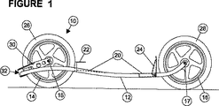
添付図面の図1〜4において、フレーム12、前輪14および後輪16を含む、本発明のスケートボード10が示されている。車輪14は、軸回転のために、軸15に取付けられ、車輪16は、軸回転のために軸17上に取付けられている。さらに、以下に説明されるように、前輪14は、横方向旋回運動が可能であるように取付けられ、後輪16は、横方向に固定されている。
【0033】
フレーム12は、スケートボード10の前部から後部へ延びる、互いに間隔を置いて配置され長手方向に延びる一対のフレーム部材18を含む。各フレーム部材18は、図2に示されているように、車輪14に近接する、外側へ湾曲されている前部と、フレーム部材18が内方へ湾曲して、互いに比較的接近している中間部分、および、フレーム部材が外側へ湾曲されている車輪16に近接する後部を含む。図1に示されているように、フレーム部材18は、車輪14の中心点に近接する点で長手方向上方へ延びて湾曲し、次いで、フレーム12の中心へ向かい下方に延びて湾曲し、次いで、上方へ湾曲して、車輪16の軸17に到達する。前輪14に近接する広幅部分により、車輪14は、相当角度にわたり旋回することが可能となる。後輪16に近接する広幅部分により、デッキ20の後部は、足を快適に収容するのに充分に幅広であることが可能となる。フレームの広幅部分が、フレームの中間領域に比して、比較的高い地上高を有することが分かる。
【0034】
2部分形デッキ20は、フレーム部材18間に取付けられている。デッキ20の前部は、平たい部材であり、平たい部材上には、L形足指押込式サポート22が取付けられている。デッキ20の後部は、足ストップを上方へ延ばした平たいプレートの形状を有する。
【0035】
車輪14は、タイヤ26を備え、車輪16は、タイヤ28を備える。
【0036】
図1に示されているように、フレーム部材18は、軸15を越えて前方へ延び、車輪14に近接する軸15の水準の下方に配置されている。図示のように、フレーム部材18は、フォーク部材30により、車輪14に接続され、フォーク部材30は、車輪14の周りを延びて軸15まで後方へ延びる。フォーク部材30は、軸15に固定接続され、ピボットにより、32の個所で、フレーム部材18の前端に旋回可能に接続されている。旋回接続点は、図1に示されているように、軸15の水準の下方に位置し、軸17の水準の下方に位置する。
【0037】
図3に示されているように、軸15からピボット32の中心点まで走行する線34は、地面に対して角度36を成す。角度36は、前述のフォーク部材角度である。さらに、線38は、ピボット32を、線34と直角を成して通過し、地面と角度40を成す。角度40は、前述のピボットの円弧角である。
【0038】
図4において、フォーク30と、タイヤ26を含む車輪14とは、フレーム部材18の間で、ピボット32を介して前方および後方に自由に旋回することが可能である。回動アーム組立30は、適切に形成されているサイドプレート100を有し、サイドプレート100は、フレーム部材18に対するストップ部として動作し、車輪14が、過度に遠くへ回動し、タイヤ26をフレーム部材18に接触させることを阻止する。
【0039】
図5において、前輪14および凸状曲線42が示され、前輪14は、凸状曲線42に沿って移動する。
【0040】
ピボット32の中心は、ピボット円弧角40が、仮に地面に対して90度を成す場合、すなわち垂直の場合には軸高さに位置し、車輪自体は、仮想の大きい3次元ドーナッツ(トーラス)を描いて、水平方向に回動することになる。
【0041】
これに対し本発明では、ピボット32の中心が、ピボット円弧角40が地面に対して、例えば45度である場合のように、軸高さより下方に位置する場合、車輪自体は傾斜して、この例の場合45度の傾斜で、仮想3次元ドーナッツを描いて回動する。仮想3次元ドーナッツの最高位置点は、フレーム18の間の中間に位置する。従って、体重が下方でピボット32に加えられる(すなわち、ライダーが、スケートボード上に立つ)場合、回動アームフォーク30は、直ちにそれ自体を、仮想3次元ドーナッツの最高位置点(凸状曲線42の頂点)にセンタリングする。
【0042】
図6〜8において、本発明のスケートボード10のためのブレーキ機構50の1つの実施例が、明瞭に示されている。
【0043】
図6に示されているように、ブレーキ機構50は、L形部材52を有し、L形部材52は、通常、ばね62により変位され、従って、上方へ延びる制動部材54は、後輪16のタイヤ28の周縁に当接する。さらに、部材52は、デッキ20の後部の下方に配置されている略水平の下部部材56を有する。下部部材56は、上方へ延びる前部58を有し、前部58は、デッキ20内の開口を貫通して突出し、略水平のボタン部分60に接続されている。ライダーが、足を、デッキ20の後部上に置いている場合、足は、ボタン部分60を下方へ押し、ボタン部分60は、部分56および前部58を下方へ旋回させる。これにより、制動部材54は、図7および8に示されているように、車輪16のタイヤ28の周縁から係合解除する。
【0044】
ライダーが、足を、デッキ20の後部から除去すると、L形部材52は、図6に示されている位置に戻り、従って、制動力が、車輪16に加えられる。
【0045】
図9〜10において、回動アームフォーク部材30をピボット32に取付ける配置が示されている。図9に示されているように、フォーク部材30は、上面プレート80と、上面プレート80に平行な底部プレート82とを含むことも可能である。
【0046】
図10に示されているように、プレート80および82は、車輪14の前の円弧84に沿って延びる。
【0047】
プレート80および82は双方とも、サイドプレート100と、ボルト86により相互接続されているフォーク組立とを介して固定接続され、ボルト86は、プレート80および82内の、位置合せされた開口を通り抜け、ナット88とねじ係合されて、ナット88を適所に係止する。プレート80と82との間のボルト86を、ベアリングハウジング90が包囲し、ベアリングハウジング90は、各フレーム部材18の前部に固定接続され、上部ローラベアリング92および下部ローラベアリング94を収容する。フランジ付接続ブシュ96は、ベアリング92内にはまり、フランジ付接続ブシュ98は、ベアリング94内にはまる。ブシュ96および98は、ボルト86およびプレート80および82と接触する。
【0048】
図9および10に示されている配置の場合、ボルト86、プレート80および82およびブシュ96および98は、ベアリングハウジング90およびフレームに対して軸回転することが可能である、何故ならばそれらは、ローラベアリング92および94により、自由回転することが可能であるであるからである。使用中、ボード10は、ライダーにより乗られ、ライダーの前足を、前輪に最も近い位置でデッキ20上に置き、後足を、後輪に最も近い位置でデッキ上に置き、おおよそは、後足サポート24に当接させる。さらに、ボタン60が、後足により押されて、ブレーキ機構50を係合解除する。
【0049】
スケートボード10は、平坦な舗装した場所およびコンクリートを含む様々な表面上、または、例えば草の生えている表面などの起伏のある地面上で、特に下り坂で、乗られることが可能である。
【0050】
フォーク部材30が、軸15の水準の下方でフレーム18に接続されている配置により、前輪14が、自動センタリングし、スケートボード10が、直立で乗られ、ライダーがカーブを走行するようにするためにスケートボード10を傾斜させる場合のみ、いずれかの側に傾斜する。このようにして、スケートボード10の走行方向は、前輪14の旋回運動を制御するためのハンドルバーのように別個のステアリング機構および装置を必要とせずに、ライダーの体重の移動により、自動的に制御される。
【0051】
当業者に自明な変更および変形は、本発明の範囲内にあると見做される。例えば、二輪スケートボード実施例が好ましいが、スケートボードは、3つ以上の車輪を有することが可能である。例えば、後部に単一車輪の代りに、一対の車輪が、単一軸または複数の軸に取付けられることが可能である。
【図面の簡単な説明】
【図1】 本発明のスケートボードの側面図である。
【図2】 図1のスケートボードの平面図である。
【図3】 図1のスケートボードの前輪の拡大側面図である。
【図4】 図3の前輪の平面図である。
【図5】 図5は前輪が、前輪の方向転換領域にわたり回動する際の前輪の凸状円弧を示す、図1〜4のスケートボードの斜視図である。
【図6】 図6は動作条件下でのブレーキを示す、図1のスケートボードの後輪の拡大側面図である。
【図7】 図7は非動作条件下でのブレーキを示す、図6に類似の図である。
【図8】 図8は図7の後輪の平面図である。
【図9】 図9は本発明のスケートボードで使用されることが可能であるフォークピボットの一実施例の側面図である。
【図10】 図10は図9のフォークピボットの平面図である。[0001]
BRIEF DESCRIPTION OF THE INVENTION
The present invention relates to a skateboard.
[0002]
Field of the Invention
In a conventional skateboard, a total of four wheels are arranged, a pair is arranged at the front part, and a pair is arranged at the rear part. All wheels have a very small diameter, which allows them to fit under the deck, where each pair has a single axis mounted on a tilt pivot, thereby When the rider shifts the weight toward the inner wheel, the maneuvering can be performed such that the inner wheels approach each other and the outer wheels are separated from each other on the unweighted side of the board. In this way, maneuvering is performed by all four wheels simultaneously.
[0003]
The disadvantage of conventional skateboard designs is that small wheels are very sensitive to surface irregularities, which makes conventional skateboards use on other than very smooth surfaces. Is impractical and dangerous. Attempts have been made to overcome these problems by forming skateboards with large wheels. However, the large wheels will cause the deck to be taller (and thus unstable) or the structure will be wider (in this case, the large wheels will extend beyond the edge of the deck), which makes the skateboard It is difficult to handle and slows down. Traditional skateboard layouts have therefore been limited to relatively smooth surfaces since the inception.
[0004]
In an attempt to move away from the limitations in conventional skateboards, a new design was proposed. One such design is formed by Barachet, who proposes a two-wheel skateboard, where both wheels are aligned along one central axis, like a scooter ( Inline). This design includes an autopilot front wheel, a fixed rear wheel and a two-part deck, where the first part of the deck is for the front leg between the two wheels and the second part is the rear wheel Behind the back leg.
[0005]
The Barachet design is held by a fork and the pivot point is located in front of the center position of the front wheels. By tilting to one side of the skateboard, the front pivot allows the front wheels to turn in the appropriate direction, thereby maneuvering the skateboard. While the front wheels turned around, these devices were found to be very unstable and very difficult to ride.
[0006]
The reason for this instability was found to be that the pivot point of the front wheel fork was higher than the axis of the front wheel. This adds the rider's weight above the center point of the front wheels, thereby increasing instability and thus the device is not practical and therefore not commercially viable.
[0007]
Furthermore, it has been found that the arc that is drawn by turning the turn when the front wheel changes direction is concave with respect to the ground because the pivot point is positioned higher than the axis of the front wheel. This creates a highly undesirable effect of trying to redirect the front wheel to the outer end when the rider's weight is added to the skateboard.
[0008]
A variant of Barachet is German Grassboards developed by Kroher. Kroher has just made two changes to the Barachet design: the pivot point of the front wheel is aligned with the axis in a horizontal direction and the single rear wheel is parallel with a short distance from each other Is replaced by two wheels. It is clear that an attempt was made to replace the single rear wheel with two rear wheels to give the skateboard some degree of stability and make the skateboard easier to ride. However, because it was sought to obtain lateral stability with the rear wheels of the two wheels, the characteristic of turning to the smooth transition side theoretically provided by the inline two-wheel skateboard was lost.
[0009]
The present invention resides in alleviating all or at least some of the aforementioned problems.
[0010]
In one aspect of the present invention, an inline skateboard comprising a longitudinally extending frame with aligned wheels, wherein the wheels are mounted on an axis, one of the wheels being a foremost steering wheel In an inline skateboard, there is provided an inline skateboard characterized in that a frame is pivotally connected to the foremost steering wheel at a position below and forward of the foremost steering wheel.
[0011]
Preferably, the fork member is connected to the shaft of the foremost steering wheel, and one end of the frame is pivotally connected to the fork member at a position below the shaft of each wheel.
[0012]
More preferably, the front end of the frame is pivotally connected to the front end of the fork member at a location below and forward of the frontmost steering wheel axis.
[0013]
When the front fork pivot pivot point is positioned lower than (and in front of) the frontmost steering wheel shaft, a convex arc is formed by the frontmost steering wheel when the frontmost steering wheel rotates over its turning angle. Therefore, stability is obtained. Accordingly, it has become known that the rider's weight is applied, and it has been found that the foremost steering wheel is automatically centered and straightened, causing stability and operability.
[0014]
Preferably, the pivot point is not so low that the pivot point hits the ground in an undulating area. In general, the pivot point is kept as low as practical without causing undesired clearance problems. However, as the pivot point is raised higher from the ground, the skateboard of the present invention becomes less stable and more difficult to control. Therefore, a compromise between stability and ground clearance must be made. In general, the fork member is preferably arranged at an angle in the region of 10 to 45 °, preferably 20 to 25 ° from the horizontal. The fork member angle itself is an imaginary line drawn from the axle to the ground via the exact center of the fork pivot. The arc angle drawn by the pivot is perpendicular to the virtual line and is a virtual line drawn along the axis of the pivot.
[0015]
In the present invention, it has also been found that the use of relatively large wheel sizes, for example at least 300 mm in diameter, increases the stability of the system. In practice, it has been found that the preferred wheel diameter is usually in the region of 400-600 mm.
[0016]
The stability provided by the skateboard of the present invention eliminates the need to assist in riding with a wheel alignment spring or return spring. When the front wheel is jumped, etc. (if the rider's weight cannot be added to the skateboard), the front wheel will automatically It is stabilized straight. Furthermore, it has been found that the fork member can be turned very freely in combination with the wheels connected to the fork member.
[0017]
Accordingly, it is preferred to use one or more high quality sealed roller bearings in the pivot mechanism to ensure that the pivot can always rotate freely. Sealed deep groove bearings provide a good example of the right type, because these deep groove bearings are designed to withstand heavy loads from several directions and prevent foreign material from entering. is there.
[0018]
Rather than using a straight side frame with a flat deck, the frame is curved outwards the most outward (to allow sufficient front wheel tuning) and the lowest position area closest to the ground It has also been found that it may be preferable to curve inwardly towards the middle and again slightly outwardly towards the rear to provide a suitable width for the rear foot position. In addition, the widest point is usually the highest position point, which provides a sufficient minimum ground clearance when turning, and the narrowest point may be closest to the ground. This type of complex 3D curve provides a structurally better frame and an aesthetically pleasing frame.
[0019]
Alternatively, extending upward from the pivot, extending around the pivot directly above the adjacent wheel, extending downward, reaching the appropriate ground level for the deck, extending toward the rear, It is also possible to have a single frame tube that is divided into two sections and supports the rear wheels.
[0020]
As an additional accessory, a brake is incorporated and brake pads and actuators acting on the rear wheels are mounted in a typical scooter fashion. However, it is considered that the rider holds the brake lever in one hand, and in this case, the brake lever is flexibly attached to the brake pad via a cable. In this way, the rider can still stand in a surf / snowboard position, while being free to move the hand holding the brake lever due to the flexible cable. The additional advantage this provides is that the skateboard of the present invention prevents runaway if not careful, and the rider intentionally slides the rear wheel under harsh braking, making it light to medium. By speed control with a certain degree of braking, it is possible to descend a steep hill in a straight line.
[0021]
In another two alternative embodiments, the skateboard of the present invention can be prevented from descending down a hill after leaving the vehicle. A first alternative embodiment is a wrist strap similar to that used by surfboard rides in surfing. The wrist strap consists of a coil of elastomeric cord, with hook and loop fastener attachments attached to each end (one attachment is for the wrist and the other attachment is for the skateboard frame is there).
[0022]
The other alternative embodiment is a rear foot actuated brake that is more purpose-built. In this example, a button is provided that is biased and displaced by a spring that rises past the deck in which the rear foot is located. Below the button biased by the spring is a plate having a bottom section attached to the button and a top section contacting the rear wheel. If no pressure from the rear foot is applied to the button (when not riding), the upper section maintains the pressure applied to the rear wheel. When the rider's hind legs are placed on the back of the deck (and on the buttons), the upper section of the plate releases its pressure from the wheels. This allows the rear wheels to turn freely as soon as the rider's hind legs are in place on the skateboard, but when the rider gets off, the brakes are automatically activated and the skate The board stops.
[0023]
This brake design allows the button to be lifted slightly below the foot in order to apply the required degree of braking force, while riding by simply angling the rear foot slightly. It can also be used as a progressive brake.
[0024]
Another attachment that can be used is a foot strap that provides for a better fit of the foot while riding the skateboard of the present invention. The foot strap consists of an angle-shaped flexible plate that extends upward from the frame, extends rearward on the front foot and forwards on the rear foot. The rider only needs to turn the rider's foot to slide down the footstrap and only return the rider's foot to release. The system is easy to use without the difficulty of forcing sliding into and out of conventional foot straps and thus without the dangers caused by slow release action. Designed to.
[0025]
However, advanced riders may prefer to use conventional foot straps of the type used by sailboards to make their feet more specially safe when performing maneuvers such as jumps.
[0026]
The skateboard of the present invention can also include a removable set of handlebars. For example, a scooter-type handlebar can be attached to a skateboard by incorporating a quick-removable attachment on the front wheel shaft or in proximity to the fork member pivot point. When the handlebar is installed, the skateboard acts as a scooter, thus the rider rushes to the scene, then removes the handlebar, descends the hill with the skateboard, and then re-engages the handlebar Install and go home.
[0027]
The skateboard of the present invention can be used in combination with a kite. By holding a handle attached to the end of the kite string, the skateboard can be moved through the wind force, thereby allowing gybs and tacking maneuvers to be achieved.
[0028]
Furthermore, the skateboard of the present invention is well suited for being driven by a prime mover via a non-steering wheel. Small oil prime movers and electric motors can be used to drive the skateboard forward on a flat surface, to roll and descend without power, and then drive the skateboard back It can even be used. An electric motor is suitable for this, because the electric motor is recharged as it travels down the hill and then switched on to drive the skateboard up and back up the hill, thus Thus, it is possible to minimize the total amount of battery drain.
[0029]
The skateboard of the present invention preferably operates from flat asphalt / bitumen, operating on surface conditions such as grass and mud, such as parks, parking lots and rugged outdoors.
[0030]
In another aspect of the present invention, as the front wheel of the skateboard of the present invention is autopilot, the rear wheel may turn in the same way if the turning radius must be short when turning. Is possible. As another alternative, the front wheels are preferably fixed as the rear wheels turn.
[0031]
The invention will now be described, by way of example, with reference to the accompanying drawings, in which:
[0032]
DESCRIPTION OF THE INVENTION
1-4 of the accompanying drawings, a
[0033]
The
[0034]
A two-
[0035]
The
[0036]
As shown in FIG. 1, the
[0037]
As shown in FIG. 3, the
[0038]
In FIG. 4, the
[0039]
In FIG. 5, the
[0040]
Center of the
[0041]
In the present invention contrast, the center of the
[0042]
6-8, one embodiment of a
[0043]
As shown in FIG. 6, the
[0044]
When the rider removes his foot from the rear of the
[0045]
9-10, the arrangement for attaching the pivot
[0046]
As shown in FIG. 10, the
[0047]
[0048]
9 and 10, the
[0049]
The
[0050]
With the arrangement in which the
[0051]
Modifications and variations obvious to those skilled in the art are deemed to be within the scope of the present invention. For example, although a two-wheel skateboard embodiment is preferred, the skateboard can have more than two wheels. For example, instead of a single wheel at the rear, a pair of wheels can be mounted on a single shaft or multiple shafts.
[Brief description of the drawings]
FIG. 1 is a side view of a skateboard according to the present invention.
FIG. 2 is a plan view of the skateboard of FIG.
FIG. 3 is an enlarged side view of a front wheel of the skateboard of FIG. 1;
4 is a plan view of the front wheel of FIG. 3. FIG.
FIG. 5 is a perspective view of the skateboard of FIGS. 1-4, showing the convex arc of the front wheel as the front wheel rotates over the direction change area of the front wheel.
FIG. 6 is an enlarged side view of the rear wheel of the skateboard of FIG. 1, showing the brake under operating conditions.
FIG. 7 is a view similar to FIG. 6, showing the brake under non-operating conditions.
FIG. 8 is a plan view of the rear wheel of FIG.
FIG. 9 is a side view of one embodiment of a fork pivot that can be used with the skateboard of the present invention.
FIG. 10 is a plan view of the fork pivot of FIG.
Claims (13)
前記最前位置ステアリングホイール(14)の軸(15)がフォーク部材(30)に連結され、前記フォーク部材(30)は、前記軸(15)の前方かつ下方で、スケートボード設置面に対して前方に傾斜した旋回軸(32)を介して、前記フレーム(12)に旋回可能に連結されていることを特徴とするスケートボード。A frame (12) extending longitudinally and having a plurality of wheels (14, 16) arranged in a row, the wheels (14, 16) being attached to shafts (15, 17), the wheels (14, 16) One (14) of the inline skateboard (10), which is the foremost steering wheel,
A shaft (15) of the foremost steering wheel (14) is connected to a fork member (30), and the fork member (30) is forward of the shaft (15) and below the skateboard installation surface. A skateboard characterized in that it is pivotally connected to the frame (12) via a pivot shaft (32) inclined to the top .
Applications Claiming Priority (5)
| Application Number | Priority Date | Filing Date | Title |
|---|---|---|---|
| AUPP1167A AUPP116797A0 (en) | 1997-12-30 | 1997-12-30 | Two wheeled skateboard |
| AU3030 | 1998-04-20 | ||
| AU1167 | 1998-04-20 | ||
| AUPP3030A AUPP303098A0 (en) | 1998-04-20 | 1998-04-20 | In-line, two-wheeled skateboard |
| PCT/AU1998/001007 WO1999034886A1 (en) | 1997-12-30 | 1998-12-30 | A skateboard |
Publications (3)
| Publication Number | Publication Date |
|---|---|
| JP2002500083A JP2002500083A (en) | 2002-01-08 |
| JP2002500083A5 JP2002500083A5 (en) | 2006-04-13 |
| JP4118512B2 true JP4118512B2 (en) | 2008-07-16 |
Family
ID=25645690
Family Applications (1)
| Application Number | Title | Priority Date | Filing Date |
|---|---|---|---|
| JP2000527326A Expired - Fee Related JP4118512B2 (en) | 1997-12-30 | 1998-12-30 | skateboard |
Country Status (12)
| Country | Link |
|---|---|
| US (1) | US6398237B1 (en) |
| EP (1) | EP1042039B1 (en) |
| JP (1) | JP4118512B2 (en) |
| CN (1) | CN1167481C (en) |
| AT (1) | ATE324935T1 (en) |
| AU (1) | AU750255B2 (en) |
| CA (1) | CA2316842C (en) |
| DE (1) | DE69834427T2 (en) |
| ES (1) | ES2264813T3 (en) |
| NZ (1) | NZ505796A (en) |
| TW (1) | TW396045B (en) |
| WO (1) | WO1999034886A1 (en) |
Families Citing this family (59)
| Publication number | Priority date | Publication date | Assignee | Title |
|---|---|---|---|---|
| US6832765B1 (en) * | 1998-12-02 | 2004-12-21 | Robert Christopher Walton | Steerable in-line skates |
| DE19953176A1 (en) * | 1999-11-04 | 2001-05-23 | Christian Zwinger | Roller board |
| DE10035296B4 (en) * | 2000-07-18 | 2006-08-24 | Bertiller, Marco | Sports and transport equipment |
| AUPQ883700A0 (en) * | 2000-07-18 | 2000-08-10 | Design Science Pty Ltd | Brake for all-terrain skateboard |
| FR2819423B1 (en) * | 2001-01-12 | 2003-03-07 | Hoggar Solution | AIRCRAFT SPORTS OR LEISURE MACHINE |
| US7083178B2 (en) * | 2001-04-11 | 2006-08-01 | Steven Dickinson Potter | Balancing skateboard |
| DE10137732A1 (en) * | 2001-06-27 | 2003-01-16 | Peter Sanftenberg | Skateboard-like riding device comprises a footboard whose top surface lies in or below the plane defined by the center lines of the flexibly mounted wheel axles |
| GB0119404D0 (en) * | 2001-08-09 | 2001-10-03 | Paddock Timothy | All-terrain board |
| US6832771B2 (en) | 2001-11-30 | 2004-12-21 | Cassady Engineering, Inc. | Wheel board vehicle |
| NZ517724A (en) * | 2002-03-11 | 2004-02-27 | Reginald Lyall Reid | Roller-skates with large wheels mounted outboard of foot-plate. |
| US6705630B1 (en) | 2002-08-23 | 2004-03-16 | Alon Karpman | Personal vehicle |
| US7306240B2 (en) * | 2003-01-17 | 2007-12-11 | Shane Chen | Turnable wheeled skate |
| US20040140634A1 (en) * | 2003-01-17 | 2004-07-22 | Shane Chen | Turnable wheeled skate |
| FR2851929B1 (en) * | 2003-03-05 | 2005-08-05 | Daniel Bridier | WHEELBOARD FOR TERRESTRIAL SURFERS |
| US7044486B2 (en) * | 2003-12-17 | 2006-05-16 | Nike, Inc. | Skateboard with suspension system |
| US7172205B1 (en) * | 2004-05-28 | 2007-02-06 | Vujtech James A | Two-wheeled riding-board apparatus |
| WO2006029044A2 (en) * | 2004-09-02 | 2006-03-16 | Crigler Daren W | Electric skateboard |
| US7213823B1 (en) * | 2005-01-13 | 2007-05-08 | Vujtech James A | Two-wheeled riding-board apparatus |
| FR2888204A1 (en) * | 2005-07-11 | 2007-01-12 | Claude Blondeau | Skate board or scooter type one-sided pedestrian rear wheel drive vehicle for e.g. board sport field, has arms with upper ends connected or supported on pivot foot of user, and jack for activating arms and tube clamp of arms |
| US7484741B2 (en) * | 2005-12-05 | 2009-02-03 | Kay Iii John F | Axle assembly for skateboard |
| US20070246308A1 (en) * | 2006-04-20 | 2007-10-25 | 6144322 Canada Inc. | Mountainboard |
| US8414000B2 (en) * | 2006-04-28 | 2013-04-09 | Razor USA, Inc. | One piece flexible skateboard |
| US7766351B2 (en) * | 2006-04-28 | 2010-08-03 | Razor Usa, Llc | One piece flexible skateboard |
| US7338056B2 (en) * | 2006-04-28 | 2008-03-04 | Razor Usa, Llc | One piece flexible skateboard |
| KR100807013B1 (en) | 2006-08-10 | 2008-03-03 | 강신기 | All-terrain Skateboards Having Self-propulsing Means |
| US7735840B2 (en) * | 2007-08-02 | 2010-06-15 | Bbc International Llc | Roller shoe |
| WO2009026626A1 (en) * | 2007-08-27 | 2009-03-05 | Design Science Pty Ltd | All-terrain skateboards |
| US7600768B2 (en) * | 2007-09-05 | 2009-10-13 | Razor Usa, Llc | One piece flexible skateboard |
| AU2008359231A1 (en) * | 2008-07-09 | 2010-01-14 | Alon Karpman | Personal vehicle |
| IT1390924B1 (en) * | 2008-07-31 | 2011-10-19 | Peruffo | METHOD OF BRAKING OF SPORTS TOOLS, BRAKING DEVICE AND SPORTS EQUIPMENT INCLUDING SUCH BRAKING DEVICE |
| US8376378B2 (en) * | 2008-11-04 | 2013-02-19 | Performance Concepts, Inc. | Self-propelled vehicle and articulated steerable mobile chassis thereof |
| US20100123295A1 (en) * | 2008-11-17 | 2010-05-20 | Pardau, Llc | Skateboard |
| US20110042913A1 (en) * | 2008-11-17 | 2011-02-24 | Pardau, Llc | Skateboard |
| IT1394607B1 (en) * | 2009-06-08 | 2012-07-05 | Bolditalia S R L | REFINEMENT IN SKIING OR TABLE ON WHEELS. |
| WO2011153997A2 (en) | 2010-05-06 | 2011-12-15 | Boehme Ulli | Scooter for descending slopes or the like |
| DE102010019622B3 (en) * | 2010-05-06 | 2011-09-29 | Ulli Böhme | Roller for descending slopes or the like |
| KR101137807B1 (en) * | 2010-06-07 | 2012-06-22 | (주)자이로 | Inline-skate wheel for improvement driving performance |
| DE102011102940A1 (en) * | 2011-05-23 | 2012-11-29 | Tobias Fink | Single-lane roller carriage of vehicle, has seat shell that is formed between front wheel and rear wheel, where front wheel is provided with friction steering portion |
| US8684376B2 (en) | 2012-01-09 | 2014-04-01 | James Wurst | Three wheel lean-steer skateboard |
| US8746716B1 (en) | 2012-01-09 | 2014-06-10 | James Wurst | Three wheel lean-steer skateboard |
| US10463948B2 (en) * | 2013-03-19 | 2019-11-05 | Kazumine Kumada | Self-propelled skateboard |
| US9211937B2 (en) * | 2013-11-26 | 2015-12-15 | Shane Chen | Leg scooter device |
| US9327182B1 (en) | 2014-04-07 | 2016-05-03 | Frank Meak | Two wheeled recreational board |
| US20160107070A1 (en) * | 2014-10-17 | 2016-04-21 | Christopher Charles John Paul Middleton | All-terrain board vehicle |
| DE202014009077U1 (en) | 2014-11-15 | 2015-01-22 | Bernhard Mezger | Nordic off-road roller skating roller one-lane roller sports equipment |
| EP3223923A1 (en) | 2014-11-26 | 2017-10-04 | Razor USA LLC | Powered wheeled board |
| USD785737S1 (en) | 2015-01-09 | 2017-05-02 | Frank Meak | Two wheeled recreational board |
| USD770585S1 (en) | 2015-05-04 | 2016-11-01 | Razor Usa Llc | Skateboard |
| US10071303B2 (en) | 2015-08-26 | 2018-09-11 | Malibu Innovations, LLC | Mobilized cooler device with fork hanger assembly |
| US10226683B2 (en) * | 2016-01-26 | 2019-03-12 | Shane Chen | In-line wheeled board device |
| USD796613S1 (en) * | 2016-02-03 | 2017-09-05 | Steven Schapiro | Hoverboard |
| US10807659B2 (en) | 2016-05-27 | 2020-10-20 | Joseph L. Pikulski | Motorized platforms |
| JP1593302S (en) | 2016-09-02 | 2017-12-18 | ||
| US11406890B1 (en) | 2017-08-25 | 2022-08-09 | David Jackson | Skateboard assembly |
| USD882008S1 (en) * | 2018-11-19 | 2020-04-21 | Kazumine Kumada | Self-propelled skateboard |
| JP2022528825A (en) | 2019-03-06 | 2022-06-16 | レイザー・ユーエスエー・エルエルシー | Powered wheel board |
| US11731678B2 (en) * | 2019-07-12 | 2023-08-22 | Rollbedder, LLC | Portable and modular roller device |
| USD905809S1 (en) * | 2019-09-05 | 2020-12-22 | Bustin Boards LLC | Electric skateboard deck |
| EP4031257A4 (en) | 2019-09-18 | 2023-12-06 | Razor USA LLC | Caster boards with removable insert |
Family Cites Families (13)
| Publication number | Priority date | Publication date | Assignee | Title |
|---|---|---|---|---|
| US1150227A (en) * | 1914-10-03 | 1915-08-17 | Elias E Ries | Motor or velocipede skate. |
| DE451163C (en) * | 1926-03-31 | 1927-10-18 | Vincent Koch | Roller skate in which the wheels are hinged with spring-loaded bearing levers |
| US3385608A (en) * | 1966-09-01 | 1968-05-28 | Albert O. Waddell | Skateboard brake |
| FR2201108B1 (en) * | 1972-09-25 | 1977-12-23 | Copier Henri | |
| US4037852A (en) * | 1976-03-17 | 1977-07-26 | Bayer Arthur J | Skateboard braking method and apparatus |
| US4127282A (en) * | 1977-02-23 | 1978-11-28 | Hans Gorlach | Skate board vehicle |
| US4181316A (en) * | 1978-05-12 | 1980-01-01 | Stiebel Eltron Gmbh & Co. Kg | Skate Board |
| FR2613314B3 (en) * | 1987-04-03 | 1989-07-28 | Carn Rozeen | BICYCLE VEHICLE WITH FRONT AND REAR STEERING WHEELS |
| FR2625688B1 (en) * | 1988-01-12 | 1991-06-07 | Barachet Jacques | TWO WHEEL TANDEM SKATEBOARD |
| AU708272B2 (en) | 1994-10-28 | 1999-07-29 | Earth Sports Products, Inc. | Sports conveyance suspension systems |
| US5544919A (en) * | 1994-10-31 | 1996-08-13 | Tinkler; Mike R. | Foot support apparatus for supporting a user's foot relative to a sportsboard |
| EP0747100A3 (en) * | 1995-06-09 | 1997-09-17 | Karl Kroher | Roll apparatus |
| JP3887459B2 (en) * | 1997-06-10 | 2007-02-28 | 清之 細田 | Standing type mobile device |
-
1998
- 1998-12-30 CA CA002316842A patent/CA2316842C/en not_active Expired - Fee Related
- 1998-12-30 WO PCT/AU1998/001007 patent/WO1999034886A1/en active IP Right Grant
- 1998-12-30 EP EP98962128A patent/EP1042039B1/en not_active Expired - Lifetime
- 1998-12-30 JP JP2000527326A patent/JP4118512B2/en not_active Expired - Fee Related
- 1998-12-30 US US09/582,357 patent/US6398237B1/en not_active Expired - Fee Related
- 1998-12-30 TW TW087121878A patent/TW396045B/en not_active IP Right Cessation
- 1998-12-30 CN CNB988132508A patent/CN1167481C/en not_active Expired - Fee Related
- 1998-12-30 ES ES98962128T patent/ES2264813T3/en not_active Expired - Lifetime
- 1998-12-30 NZ NZ505796A patent/NZ505796A/en unknown
- 1998-12-30 DE DE69834427T patent/DE69834427T2/en not_active Expired - Fee Related
- 1998-12-30 AU AU17435/99A patent/AU750255B2/en not_active Ceased
- 1998-12-30 AT AT98962128T patent/ATE324935T1/en not_active IP Right Cessation
Also Published As
| Publication number | Publication date |
|---|---|
| CN1284006A (en) | 2001-02-14 |
| CA2316842C (en) | 2008-04-22 |
| NZ505796A (en) | 2001-12-21 |
| ES2264813T3 (en) | 2007-01-16 |
| CN1167481C (en) | 2004-09-22 |
| EP1042039B1 (en) | 2006-05-03 |
| US6398237B1 (en) | 2002-06-04 |
| ATE324935T1 (en) | 2006-06-15 |
| EP1042039A1 (en) | 2000-10-11 |
| DE69834427T2 (en) | 2007-04-19 |
| AU750255B2 (en) | 2002-07-11 |
| CA2316842A1 (en) | 1999-07-15 |
| EP1042039A4 (en) | 2005-01-19 |
| WO1999034886A1 (en) | 1999-07-15 |
| JP2002500083A (en) | 2002-01-08 |
| DE69834427D1 (en) | 2006-06-08 |
| AU1743599A (en) | 1999-07-26 |
| TW396045B (en) | 2000-07-01 |
Similar Documents
| Publication | Publication Date | Title |
|---|---|---|
| JP4118512B2 (en) | skateboard | |
| US4795181A (en) | Skateboard | |
| US5601299A (en) | Inline skateboard | |
| US6848527B2 (en) | Motorized skateboard-type vehicle | |
| US20090066150A1 (en) | Cam Action Caster Assembly for Ride-On Devices | |
| US20020070519A1 (en) | Dual-footboard scooter | |
| US4681333A (en) | Wind propelled land vehicle | |
| CA2519333A1 (en) | Winter recreational vehicle | |
| AU2009242669A1 (en) | Bi-directional propulsion caster | |
| US6273439B1 (en) | Scooter | |
| US8505937B2 (en) | Skating device | |
| US20050236783A1 (en) | Personal conveyance for recreational use | |
| JP2010530290A (en) | Step board | |
| US20030214113A1 (en) | Vehicle having independently articulating rear frame members | |
| US11305830B2 (en) | Motor driven vehicle | |
| US20040238251A1 (en) | Small and lightweight snow vehicle | |
| JP2020032991A (en) | Motor-driven skateboard | |
| JP3665332B2 (en) | Wheel vehicle | |
| US20040155416A1 (en) | Smooth surface sliding system for ground vehicle | |
| KR100452140B1 (en) | Truck of Skateboard and Skateboard Using the Same | |
| KR20050105912A (en) | Walking vehicle | |
| NZ563924A (en) | Riding apparatus and usage thereof |
Legal Events
| Date | Code | Title | Description |
|---|---|---|---|
| A621 | Written request for application examination |
Free format text: JAPANESE INTERMEDIATE CODE: A621 Effective date: 20051226 |
|
| A521 | Request for written amendment filed |
Free format text: JAPANESE INTERMEDIATE CODE: A523 Effective date: 20060221 |
|
| A131 | Notification of reasons for refusal |
Free format text: JAPANESE INTERMEDIATE CODE: A131 Effective date: 20071023 |
|
| A521 | Request for written amendment filed |
Free format text: JAPANESE INTERMEDIATE CODE: A523 Effective date: 20080118 |
|
| TRDD | Decision of grant or rejection written | ||
| A01 | Written decision to grant a patent or to grant a registration (utility model) |
Free format text: JAPANESE INTERMEDIATE CODE: A01 Effective date: 20080328 |
|
| A61 | First payment of annual fees (during grant procedure) |
Free format text: JAPANESE INTERMEDIATE CODE: A61 Effective date: 20080423 |
|
| R150 | Certificate of patent or registration of utility model |
Free format text: JAPANESE INTERMEDIATE CODE: R150 |
|
| FPAY | Renewal fee payment (event date is renewal date of database) |
Free format text: PAYMENT UNTIL: 20110502 Year of fee payment: 3 |
|
| LAPS | Cancellation because of no payment of annual fees |