JP4116823B2 - Mudguard structure in scooter type vehicle. - Google Patents
Mudguard structure in scooter type vehicle. Download PDFInfo
- Publication number
- JP4116823B2 JP4116823B2 JP2002151391A JP2002151391A JP4116823B2 JP 4116823 B2 JP4116823 B2 JP 4116823B2 JP 2002151391 A JP2002151391 A JP 2002151391A JP 2002151391 A JP2002151391 A JP 2002151391A JP 4116823 B2 JP4116823 B2 JP 4116823B2
- Authority
- JP
- Japan
- Prior art keywords
- pipe
- wall
- connecting tube
- engine
- frame
- Prior art date
- Legal status (The legal status is an assumption and is not a legal conclusion. Google has not performed a legal analysis and makes no representation as to the accuracy of the status listed.)
- Expired - Fee Related
Links
Images


Classifications
-
- B—PERFORMING OPERATIONS; TRANSPORTING
- B62—LAND VEHICLES FOR TRAVELLING OTHERWISE THAN ON RAILS
- B62J—CYCLE SADDLES OR SEATS; AUXILIARY DEVICES OR ACCESSORIES SPECIALLY ADAPTED TO CYCLES AND NOT OTHERWISE PROVIDED FOR, e.g. ARTICLE CARRIERS OR CYCLE PROTECTORS
- B62J15/00—Mud-guards for wheels
-
- B—PERFORMING OPERATIONS; TRANSPORTING
- B62—LAND VEHICLES FOR TRAVELLING OTHERWISE THAN ON RAILS
- B62J—CYCLE SADDLES OR SEATS; AUXILIARY DEVICES OR ACCESSORIES SPECIALLY ADAPTED TO CYCLES AND NOT OTHERWISE PROVIDED FOR, e.g. ARTICLE CARRIERS OR CYCLE PROTECTORS
- B62J23/00—Other protectors specially adapted for cycles
-
- B—PERFORMING OPERATIONS; TRANSPORTING
- B62—LAND VEHICLES FOR TRAVELLING OTHERWISE THAN ON RAILS
- B62J—CYCLE SADDLES OR SEATS; AUXILIARY DEVICES OR ACCESSORIES SPECIALLY ADAPTED TO CYCLES AND NOT OTHERWISE PROVIDED FOR, e.g. ARTICLE CARRIERS OR CYCLE PROTECTORS
- B62J37/00—Arrangements of fuel supply lines, taps, or the like, on motor cycles or engine-assisted cycles
Landscapes
- Engineering & Computer Science (AREA)
- Mechanical Engineering (AREA)
- Automatic Cycles, And Cycles In General (AREA)
Description
【0001】
【発明の属する技術分野】
本発明は、エンジンおよび変速機から成るとともに後部には後輪が軸支されるパワーユニットの前部が、操向ハンドルを操向自在に支承するヘッドパイプを前端に有する車体フレームに上下に揺動可能に支承され、ライダーを座乗させるようにして前記パワーユニットの上方に配置されるシートおよび前記操向ハンドル間に、ライダーの足を載せるステップフロアが配置され、前記パワーユニットおよび前記シート間には、該シートで上端開口部が閉鎖されるようにして収納ボックスが配置されるスクータ型車両に関し、特に、後輪からはね上げられる泥水等が、エンジンにかかるのを防止するための構造に関する。
【0002】
【従来の技術】
たとえば特許第2942561号公報で開示されたスクータ側車両では、収納ボックスの前部にその下縁から下方に垂下する前板が一体に設けられ、その前板に取付けられるゴム製の泥よけ板により、後輪ではね上げられた泥水等がエンジン側に飛散するのを防止するようにしている。
【0003】
【発明が解決しようとする課題】
ところが上記従来のものでは、後輪からはね上げられた泥水等がエンジンにかかるのを防止するために、収納ボックス以外に泥よけ板が必要であり、部品点数が少ないとは言い難く、しかも収納ボックスに泥よけ板を取付けるための作業が必要であり、組付け作業工数もその分だけ多くなる。
【0004】
本発明は、かかる事情に鑑みてなされたものであり、部品点数の低減および組付け作業工数の低減を図りつつ、後輪からはね上げられた泥水等がエンジンにかかるのを防止し得るようにしたスクータ型車両における泥よけ構造を提供することを目的とする。
【0005】
【課題を解決するための手段】
上記目的を達成するために、請求項1記載の発明は、エンジンおよび変速機から成るとともに後部には後輪が軸支されるパワーユニットの前部が、操向ハンドルを操向自在に支承するヘッドパイプを前端に有する車体フレームに上下に揺動可能に支承され、ライダーを座乗させるようにして前記パワーユニットの上方に配置されるシートおよび前記操向ハンドル間に、ライダーの足を載せるステップフロアが配置され、前記パワーユニットおよび前記シート間には、該シートで上端開口部が閉鎖されるようにして収納ボックスが配置されるスクータ型車両において、エンジンの上部に接続される吸気管、該吸気管の上流端に接続される気化器、該気化器よりも後方に配置されるエアクリーナ、ならびにエアクリーナおよび気化器間を結ぶコネクティングチューブを備えていて、車体フレームに対しパワーユニットと共に上下揺動する吸気系が、前記エンジンおよび前記収納ボックス間に配置され、前記コネクティングチューブが、エアクリーナから車幅方向に延出する第1部分と、その第1部分から彎曲部を介して滑らかに接続されて前方に延びる第2部分とを有していて、その第1部分の外周面上部に、上方に突出し且つ車幅方向に延びる立ち上がり壁が一体に設けられ、その立ち上がり壁と、前記収納ボックスの下部に一体に設けられて下方に垂下する垂下壁とが、前記後輪からはね上げられる泥水等が前記コネクティングチューブよりも前方に侵入するのを防止する迷路を前記立ち上がり壁および前記垂下壁間に形成するようにして、互いに前後に重なる位置に配置されることを特徴とする。
【0006】
このような構成によれば、コネクティングチューブの上部(エアクリーナから車幅方向に延出する第1部分の外周面上部)に一体に設けられて車幅方向に延びる立ち上がり壁と、収納ボックスの下部に一体に設けられて下方に垂下する垂下壁とで迷路が形成されるので、後輪ではね上げられる泥水等がコネクティングチューブよりも前方側に向かうのを極力阻止することができ、しかも収納ボックスおよびコネクティングチューブ以外の部品は不要であるので、部位品点数の低減を図るとともに組付け作業工数の低減を図ることができる。
【0007】
また請求項2記載の発明は、上記請求項1記載の発明の構成に加えて、前記コネクティングチューブの下部には、前記後輪からはね上げられる泥水等が前方に向かうのを阻止する泥よけ壁が前記コネクティングチューブから下方に垂下するようにして一体に設けられることを特徴とし、かかる構成によれば、後輪ではね上げられる泥水等がコネクティングチューブよりも前方側に向かうのをより一層確実に阻止することができる。
【0010】
また請求項3記載の発明は、上記請求項2記載の発明の構成に加えて、前記泥よけ壁が、前記コネクティングチューブの外周下部に沿う後半部と、前記彎曲部より離反する前半部とを有して平面視でS字状に形成されることを特徴とする。
【0012】
【発明の実施の形態】
以下、本発明の実施形態を、添付図面に示す本発明の一実施例に基づいて説明する。
【0013】
図1〜図23は本発明の一実施例を示すものであり、図1はスクータ型自動二輪車の側面図、図2は車体カバーおよび収納ボックスを省略した状態でのスクータ型自動二輪車の後部斜視図、図3は車体フレームの側面図、図4は図3の4矢視拡大図、図5は図4から泥よけ部材および防振リンクを除いた状態の平面図、図6は図1の6矢示部拡大縦断面図、図7は図4の7−7線断面図、図8は防振リンクの平面図、図9は車体カバーおよび収納ボックスを省略した状態でのスクータ型自動二輪車の中間部斜視図、図10はエアクリーナおよびコネクティングチューブを上方から見た平面図、図11はエアクリーナを省略した状態での図10の11−11線に沿う側面図、図12は車体カバーを省略した状態のスクータ型自動二輪車の上部を後方から見た図、図13は吸気チューブの上流端のリヤフレームパイプへの接続部を示すための要部切欠き断面図、図14は二次空気制御弁の構成を示す縦断面図、図15は図6の15−15線断面図、図16はステップフロアの斜視図、図17はステップフロアの一部平面図、図18は泥よけ部材の正面図、図19は図18の19矢視側面図、図20は図19の20矢視平面図、図21は図18の21−21線断面図、図22は図18の22−22線断面図、図23は図18の23−23線断面図である。
【0014】
先ず図1〜図5において、スクータ型自動二輪車の車体フレーム25は、前端にヘッドパイプ26が固着されたメインフレームパイプ27と、該メインフレームパイプ27の後端に直角に固着されるクロスパイプ28と、クロスパイプ28の両端部に前端がそれぞれ連設される左右一対のリヤフレームパイプ29,30とを備える。
【0015】
メインフレームパイプ27は、ヘッドパイプ26から後ろ下がりに傾斜したダウンフレーム部27aと、ダウンフレーム部27aの後端からほぼ水平にして後方に延びるロアフレーム部27bとが一体に連設されて成り、ロアフレーム部27bの後端部には、上下方向に押し潰されて成る筒状のラバー支持部31が形成される。クロスパイプ28は車体フレーム25の左右方向に延びるものであり、該クロスパイプ28の軸方向中央部を前記ラバー支持部31が貫通するようにして、クロスパイプ28の軸方中央部がメインフレームパイプ27の後端部に直角に固着される。またクロスパイプ28およびメインフレームパイプ27間には、クロスパイプ28およびメインフレームパイプ27の連設部を補強するための上下一対の補強部材32,33が設けられる。
【0016】
左右一対のリヤフレームパイプ29,30は、前記クロスパイプ28の両端部から後ろ上がりに延びるライズフレーム部29a,30aと、ライズフレーム部29a,30aの後端からほぼ水平にして後方に延びるととともに後端部開口が相互に対向するように水平面内で彎曲するアッパーフレーム部29b,30bとが一体に連設されて成るものである。
【0017】
前記ヘッドパイプ26には前輪WFを跨ぐフロントフォーク34が操向可能に支承され、フロントフォーク34の上端には操向ハンドル35が連結される。
【0018】
車体フレーム25における両リヤフレームパイプ29,30の前部には、後輪WRの前方側に配置されるエンジンEと、後輪WRの左側方に配置される無段変速機Mとから成るパワーユニットPが、上下に揺動することを可能として支承され、後輪WRはパワーユニットPの後部に軸支される。而してエンジンEは、シリンダをほぼ水平に配置した単気筒の4サイクルエンジンであり、無段変速機Mは、たとえばベルト式のものである。
【0019】
パワーユニットPの後部と、左右一対のリヤフレームパイプ29,30のうち左側のリヤフレームパイプ29との間にはリヤクッションユニット36が設けられる。またエンジンEからの排気ガスを導く排気管37がエンジンEから後輪WRの右側方側に延出されており、この排気管37は、後輪WRの右側方に配置される排気マフラー38に接続される。
【0020】
両リヤフレームパイプ29,30の前部間には、ヘルメット等を収納可能な収納ボックス39が、前記エンジンEの上方に配置されるようにして支持されており、両リヤフレームパイプ29,30の後部間には燃料タンク40が支持される。
【0021】
ところで、パワーユニットPは防振リンク41を介して車体フレーム25に上下揺動可能に支承されるものであり、この防振リンク41の構造について、図6〜図8を併せて参照しつつ説明する。
【0022】
防振リンク41は、パワーユニットPの前寄り下部に設けられる左右一対のエンジン側ブラケット42,42と、車体フレーム25の両リヤフレームパイプ29,30におけるライズフレーム部29a,30aの下部にそれぞれ設けられる左右一対のフレーム側ブラケット43,43と、前記両エンジン側ブラケット42,42間に配置される円筒状の回動筒44と、該回動筒44を回動可能に支承するようにして両エンジン側ブラケット42,42間に設けられる連結軸45と、横断面矩形の筒状に形成されて前記回動筒44に一端が固着される左右一対のリンク部材46,46と、前記両フレーム側ブラケット43,43間に配置されるとともに前記リンク部材46,46の他端が固着される円筒状の外筒47と、該外筒47内に同軸に配置される円筒状の内筒48と、内筒48の両端部に内周がそれぞれ焼き付けられるとともに前記外筒47の両端部に圧入される円筒状のケース49に外周がそれぞれ焼き付けられるゴムブッシュ50…と、前記内筒48を回動可能に支承するようにして前記両フレーム側ブラケット43,43間に設けられる揺動支軸51と、前記外筒47の軸方向中間部に固着されて前方に延びるアーム52と、アーム52の先端に装着されるストッパラバー53とを備える。
【0023】
前記ストッパラバー53は、メインフレームパイプ27の後端に形成されているラバー支持部31に、該ラバー支持部31の上下内面にストッパラバー53の上下両面を接触させるようにして挿入される。
【0024】
このような防振リンク41では、パワーユニットPのエンジンEから揺動支軸51に作用する荷重は、ゴムブッシュ50…の弾性変形によって吸収されるとともに、ストッパラバー53がラバー支持部31の上下内面に押付けられて弾性変形することにより吸収される。
【0025】
しかも両リンク部材46,46には、パワーユニットPよりも前方の各部材のうち最も低い位置にあってフレーム側ブラケット43よりも低くなるようにして、各リンク部材46,46よりも下方に膨出するガード部材54,54がそれぞれ固着される。これらのガード部材54…は、軽量化および高強度化を図るために、たとえば棒鋼(パイプ)を半円状に彎曲させて形成されるものである。
【0026】
図9を併せて参照して、エンジンEの吸気系57は、エンジンEの上部に接続される吸気管58と、該吸気管58の上流端に接続される気化器59と、該気化器59よりも後方で後輪WRの左側方に配置されるエアクリーナ60と、エアクリーナ60および気化器59間を結ぶ合成樹脂製のコネクティングチューブ61とを備え、収納ボックス39およびエンジンE間に配置されている。
【0027】
図10および図11をさらに併せて参照して、エアクリーナ60は、後輪WRの上部左側に配置されるようにしてパワーユニットPの後部に取付けられる。またコネクティングチューブ61は、後輪WRの上部左側に配置されるエアクリーナ60と、後輪WRの前方に配置される気化器59とを結ぶようにしてほぼ水平面内で彎曲するように配置されるものである。
【0028】
即ち、コネクティングチューブ61は、エアクリーナ60から車幅方向に延出する第1部分と、その第1部分から彎曲部を介して滑らかに接続されて前方に延びる第2部分とを有しており、そのコネクティングチューブ61の上部(即ち、前記第1部分の外周面上部)には、該コネクティングチューブ61から上方に突出し且つ車幅方向に延びる立ち上がり壁61aが一体に突設されており、コネクティングチューブ61の上方に配置されている収納ボックス39の下部には、前記後輪WRの前方で前記立ち上がり壁61aと前後に重なる垂下壁39aが、下方に垂下するようにして一体に設けられる。而して立ち上がり壁61aおよび垂下壁39a間には、後輪WRからはね上げられる泥水等がコネクティングチューブ61よりも前方すなわち気化器59側に侵入するのを防止する迷路62が形成される。
【0030】
またコネクティングチューブ61の下部には、後輪WRからはね上げられる泥水等が前方に向かうのを阻止する泥よけ壁61bが、コネクティングチューブ61から下方に垂下するようにして一体に設けられる。その泥よけ壁61bは、図10,図11に示されるように、コネクティングチューブ61の外周下部に沿う後半部と、前記彎曲部より離反する前半部とを有して平面視でS字状に形成される。
【0031】
図12を併せて参照して、両リヤフレームパイプ29,30のうち左側のリヤフレームパイプ29におけるアッパーフレーム部29bの前部には、エンジンEの排気ポート(図示せず)に供給する二次空気を浄化するための二次空気用エアクリーナ63が支持される。
【0032】
この二次空気用エアクリーナ63の吸入口には吸気チューブ64の下流端が接続されており、該吸気チューブ64の上流端は、図13で示すように、両リヤフレームパイプ29,30のうち右側のリヤフレームパイプ30におけるアッパーフレーム部30bの後端部にその後端部開口30cから挿入される。しかも吸気チューブ64の上流端は、その外面およびリヤフレームパイプ30の内面間に圧縮状態で介装される防音材65によってリヤフレームパイプ30に支持されており、防音材65は、通気性を有する弾性材料たとえばスポンジ等から成るものである。すなわち吸気チューブ64の上流端は、防音材65をリヤフレームパイプ30の内面との間に介在させてリヤフレームパイプ30の後端部開口30cに挿入されている。
【0033】
前記吸気チューブ64を、滑らかに彎曲させてリヤフレームパイプ30の後端部開口30cに挿入するために、他方のリヤフレームパイプ29の後端下部は、下方に向かうにつれてリヤフレームパイプ30から遠ざかるように傾斜した傾斜面29cを形成するようにカットされており、吸気チューブ64は、その傾斜面29cに沿うように配置される。
【0034】
エンジンEおよび二次空気用エアクリーナ63間に設けられる二次空気制御弁66が、左側のリヤフレームパイプ29のライズフレーム部29aの上部に取付けられたステー67で支持されており、該二次空気制御弁66は、前記二次空気用エアクリーナ63がライズフレーム部29aの後方に配置されるのに対し、ライズフレーム部29aを二次空気用エアクリーナ63との間に挟むようにしてライズフレーム部29aの前方に配置される。
【0035】
図14において、二次空気制御弁66は、ダイヤフラムアクチュエータ68と、該ダイヤフラムアクチュエータ68で閉弁駆動される開閉弁69と、エンジンEの排気ポート側への空気の流通だけを許容するリード弁70とで構成される。
【0036】
ダイヤフラムアクチュエータ68は、ケーシング71と、該ケーシング71で周縁部を挟持されたダイヤフラム72と、該ダイヤフラム72の中央部に一端が連結される金属製のロッド73とを備える。
【0037】
ケーシング71は、ボディ74と、前記ダイヤフラム72の周縁部を相互間に気密に挟持して該ボディ74に締結されるカバー75とから成るものであり、カバー75およびダイヤフラム72間には該ダイヤフラム72の一面を臨ませる負圧室76が形成され、ボディ74およびダイヤフラム72間には大気圧室77が形成される。カバー75の中央部には、先端に絞り孔78を有する接続管部79が連設されており、前記絞り孔78を介して負圧室76内に通じる負圧取出管路80が接続管部79に接続され、該負圧取出管路80は、吸気系57の吸気管58に接続される。これにより負圧室76には吸気管58内の負圧が作用することになる。
【0038】
ロッド73は、ボディ74により軸方向移動可能に支承されており、該ロッド73の一端は大気圧室77側で前記ダイヤフラム72の中央部に直接連結される。
【0039】
このようなダイヤフラムアクチュエータ68においては、吸気管58内の負圧が高くなったときには、ダイヤフラム72が負圧室76の容積を減少する方向に撓み、ロッド73が図14の左方に作動することになる。
【0040】
開閉弁69は、弁ハウジング81と、前記ロッド73の他端に固着される弁体82と、弁ハウジング81および弁体82間に設けられる戻しばね83とを備える。
【0041】
弁ハウジング81は、前記ボディ74と、該ボディ74に気密に締結されるサクションカバー84とで構成されるものであり、ボディ74には、空気流通路85と、空気流通路85を大気圧室77に連通せしめる連通孔86と、空気流通路85の上流端に通じて前記ロッド73と同軸に配置される弁孔87と、前記空気流通路85とは反対側で前記弁孔87を中央部に開口させた弁座88と、前記弁孔87に一部を同軸に挿入せしめた支持筒部89とが設けられ、弁孔87を同軸に貫通するロッド73が前記支持筒部89内に軸方向摺動可能に嵌合される。
【0042】
前記ボディ74およびサクションカバー84間には弁室90が形成される。またサクションカバー84には弁室90に通じる接続管部91が一体に形成されており、管路92の下流端が接続管に接続される。而して管路92の上流端は二次空気用エアクリーナ63に接続される。
【0043】
前記弁座88は弁室90に臨むようにしてボディ74に形成され、弁座88に着座することを可能として弁室90に収納される弁体82がロッド73の他端に固設される。
【0044】
また戻しばね83は、前記支持筒部89を囲繞するコイル状のものであり、弁体82を弁座88から離座せしめる方向、すなわちダイヤフラムアクチュエータ68のダイヤフラム72を大気圧室77側に撓ませる方向のばね力を発揮してボディ74および弁体82間に設けられる。
【0045】
リード弁70は、弁孔93を中央部に有して円板状に形成される弁支持板94に、前記弁孔93の開閉を可能として支持されるものであり、弁支持板94は、前記弁孔93を空気流通路85の下流端に連通させるようにして、前記ボディ74ならびに該ボディ74に締結されるカバー95間に気密に挟持される。またカバー95および弁支持板94間には前記リード弁70を収納する弁室96が形成され、弁室96に通じるようにしてカバー95に一体に設けられた接続管部97に、二次空気供給管路98の上流端が接続される。而して二次空気供給管路98の下流端は、エンジンEの排気ポートに通じるようにしてエンジンEの下部に接続される。
【0046】
このような二次空気制御弁66は、ボディ74に一体に設けられるフランジ部77aが、ステー67に締結されることにより、左側のリヤフレームパイプ29におけるライズフレーム部29aの上部に支持される。
【0047】
また左側のリヤフレームパイプ29におけるライズフレーム部29aの下部には、該ライズフレーム部29a内に通じる接続管部99が設けられており、パワーユニットPの無段変速機M内から冷却空気を導出するためのダクト100が前記接続管部99に接続される。
【0048】
図1に注目して、車体フレーム25は、合成樹脂製の車体カバー101で覆われるものであり、この車体カバー101は、運転者の足の前方を覆うレッグシールド102と、ライダーの足を載せるべくレッグシールド102の下部に連なるステップフロア103と、ステップフロア103に連なって車体後部を両側から覆うサイドカバー104とを備える。
【0049】
前記収納ボックス39および燃料タンク40は、上記サイドカバー104で覆われており、ライダーを座乗させるようにして収納ボックス39を上方から覆うシート105が、サイドカバー104の上部に開閉可能に取付けられる。すなわちステップフロア103は、操向ハンドル35およびシート105間に配置されるようにして車体カバー101に形成され、ステップフロア103の後端よりも下方に、パワーユニットPを車体フレーム25に揺動可能に支承するためのフレーム側ブラケット43…が配置される。
【0050】
メインフレームパイプ27におけるロアフレーム部27bの前部には、支持部材106が固着されており、前記ロアフレーム部27bの上方で自動二輪車の左右方向に延びる前部支持パイプ107の中央部が前記支持部材106に固着される。またクロスパイプ28の両端部には後部支持パイプ108,108が立設されており、前部支持パイプ107の両端部および後部支持パイプ108、108の上端部に、ロアフレーム部27bと平行に延びる一対のフロア支持フレーム109,109が固着される。
【0051】
図6で示すように、ステップフロア103の左右両側における前部および後部には、前記フロア支持フレーム109,109の前部および後部上面に当接するボス部103a,103aが下方に突出するようにして一体に設けられており、それらのボス部103a,103a…がフロア支持フレーム109,109に締結されることで、ステップフロア103が両フロア支持フレーム109,109に支持される。
【0052】
図15〜図17において、ステップフロア103の略中央部には、上部を開放した箱形のバッテリ収納ボックス110が、ステップフロア103から下方に突出するようにして一体に形成され、このバッテリ収納ボックス110の上部開口端は、ステップフロア103に着脱可能に取付けられる合成樹脂製の蓋板111で閉鎖される。
【0053】
バッテリ収納ボックス110内には、バッテリ112、CDIユニット113、スタートリレー114およびヒューズボックス115等が収納、固定される。しかもバッテリ収納ボックス110の後壁110aには、前記バッテリ112、CDIユニット113、スタートリレー114およびヒューズボックス115等に接続される配線118をバッテリ収納ボックス110内に引き込むための開口部117が設けられる。
【0054】
車体フレーム25のうち前記ステップフロア103の下方を通るロアフレーム部27bの後端には、エンジンE側に泥水等がはね上げられるのを防止する合成樹脂製の泥よけ部材120が設けられる。
【0055】
ており、この泥よけ部材120は、ロアフレーム部27bの後端に固着されるクロスパイプ28を少なくとも前方から覆って該クロスパイプ28に取付けられる。
【0056】
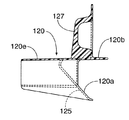
図18〜図23において、泥よけ部材120は、ロアフレーム部27bの後端に固着されるクロスパイプ28を少なくとも前方から覆うように形成されるものであり、クロスパイプ28を前方側から覆う前壁120aと、前壁120aの上端から後方にほぼ水平に延びるように形成される上壁120bと、前壁120aおよび上壁120bに連なる一対の側壁120c,120dと、下方に開いた略U字状の横断面形状を有して前壁120aの略中央部から前方に延びるカバー部120eとを一体に備える。
【0057】
前記上壁120bはクロスパイプ28を上方から覆うものであり、また両側壁120c,120dで前記クロスパイプ28の両端が覆われる。すなわち泥よけ部材120は、クロスパイプ28を、その前方、上方および両側から覆うように形成されることになる。またロアフレーム部27bの後部はカバー部120eで上方から覆われる。
【0058】
ところで、クロスパイプ28およびメインフレームパイプ27の連設部を補強するためにクロスパイプ28およびメインフレームパイプ27間に設けられた上下一対の補強部材32,33のうち下方の補強部材33には、前記泥よけ部材120における上壁120bの左右両側に下方から当接する一対の支持腕部33a,33aが一体に設けられており、それらの支持腕部33a…にはウエルドナット121…が固着される。一方、支持腕部33a…に対応する部分で前記上壁120bには一対の挿通孔122,122が設けられており、それらの挿通孔122…に挿通されるねじ部材123…を前記ウエルドナット121…に螺合して締めつけることにより泥よけ部材120が両支持腕部33a…に取付けられる。
【0059】
前記カバー部120eの右側で前壁120aの上部には、バッテリ収納ボックス110の右側後部を収納するための収納凹部124が設けられる。
【0060】
この泥よけ部材120の前面の少なくとも下部、この実施例では前記収納凹部124を除く前壁120aの前面に、前上がりに傾斜した傾斜面125が形成される。またクロスパイプ28の両端開口部を覆う両側壁120c,120dの下部にも、下方に向かうにつれて内方位置となる傾斜面126,126が形成され、クロスパイプ28の両端下部もそれらの傾斜面126…に対応して斜めに切除される。
【0061】
ところで、ステップフロア103に一体に設けられたバッテリ収納ボックス110の後壁110aには、バッテリ収納ボックス110内に引き込まれる配線118用の開口部117が設けられているが、泥よけ部材120の上壁120bには、前記開口部117を後方側から覆う遮蔽壁127が上方に突出するようにして一体に形成される。
【0062】
さらに前記両挿通孔122,122のうち左側の挿通孔122よりも前方で上壁120bの前部には、周方向1箇所にスリット129を有して円形に形成される保持部128が一体に形成されており、この保持部128には、前記スリット129から挿入することにより、ハーネスおよびケーブル類を保持することが可能である。
【0063】
次にこの実施例の作用について説明すると、パワーユニットPの前部を車体フレーム25に上下揺動可能に支承するための一対のリンク部材46…は、ステップフロア103の後端よりも下方に配置されて車体フレーム25の一部を構成するフレーム側ブラケット43…と、パワーユニットPの下部に設けられた一対のエンジン側ブラケット42…とを連結するものであり、これらのリンク部材46…には、該リンク部材46…よりも下方に膨出するガード部材54…がそれぞれ固着されている。しかもガード部材54…は、パワーユニットPよりも前方の各部材のうち最も低い位置にあってフレーム側ブラケット43よりも低くなるようにして下方に膨出している。
【0064】
したがって縁石等の障害物に乗り上げたときには、パワーユニットPよりも先に障害物がガード部材54…に当たることになり、リンク部材46…がパワーユニットPを上方に浮き上がらせるように回動するので、パワーユニットPに障害物が直接衝突することを回避することができる。しかもリンク部材46…にガード部材54…を固設するだけの極めて簡単な構造でパワーユニットPへの障害物の衝突を回避することができる。
【0065】
ところで、パワーユニットPよびシート105間には、該シート105で上端開口部が閉鎖されるようにして収納ボックス39が配置されており、エンジンEの上部に接続される吸気管58、該吸気管58の上流端に接続される気化器59、該気化器59よりも後方に配置されるエアクリーナ60、ならびにエアクリーナ60および気化器59間を結ぶコネクティングチューブ61を備える吸気系57が、エンジンEおよび収納ボックス39間に配置されている。しかもコネクティングチューブ61の上部に一体に設けられて上方に突出する立ち上がり壁61aと、収納ボックス39の下部に一体に設けられて下方に垂下する垂下壁39aとが、後輪WRからはね上げられる泥水等がコネクティングチューブ61よりも前方に侵入するのを防止する迷路62を立ち上がり壁61aおよび垂下壁39a間に形成するようにして前後に重なる位置に配置されている。
【0066】
したがって後輪WRではね上げられる泥水等がコネクティングチューブ61よりも前方のエンジンE側に向かうのを極力阻止することができ、しかも収納ボックス39およびコネクティングチューブ61以外の部品は不要であるので、部品点数の低減を図るとともに組付け作業工数の低減を図ることができる。
【0067】
またコネクティングチューブ61の下部には、後輪WRからはね上げられる泥水等が前方に向かうのを阻止する泥よけ壁61bがコネクティングチューブ61から下方に垂下するようにして一体に設けられており、後輪WRではね上げられる泥水等がコネクティングチューブ61よりも前方側に向かうのを、前記泥よけ壁61bによってより一層確実に阻止することができる。
【0068】
また車体フレーム25は、ステップフロア103の下方を通るロアフレーム部27bを備えており、このロアフレーム部27bの後端には、エンジンE側に泥水等がはね上げられるのを防止する泥よけ部材120が設けられている。
【0069】
このため大型のアンダーカバーを用いていた従来のものと比べて部品コストを低減することを可能としつつ、エンジンE側に泥水等がはね上げられるのを防止することができる。
【0070】
また車体フレーム25は、車体フレーム25の左右方向に延びて前記ロアフレーム部27bの後端に固着されるクロスパイプ28を備えており、泥よけ部材120は、クロスパイプ28を少なくとも前方から覆うように形成されるので、車体フレーム25の左右方向のほぼ全体にわたって泥水がエンジンE側にはね上げられるのを防止することができる。
【0071】
また泥よけ部材120の前面の少なくとも下部には、前上がりに傾斜した傾斜面125が形成されており、泥よけ部材120に衝突した泥水等を泥よけ部材125の後方かつ下方へと前記傾斜面125で案内することで、エンジンE側への泥水等のはね上がりをより確実に防止することができる。
【0072】
ところで、ステップフロア103には、バッテリ112等を収納するバッテリ収納ボックス110が設けられ、該バッテリ収納ボックス110の後壁110aには、バッテリ収納ボックス110内に引き込まれる配線118用の開口部117が設けられるのであるが、前記泥よけ部材120には、その開口部117を後方側から覆う遮蔽壁127が一体に形成されている。したがって専用の部品を設けることなくバッテリ収納ボックス110内に泥水等が侵入するのを防止することができる。
【0073】
しかも泥よけ部材120は、クロスパイプ28の両端開口部を覆うように形成されるので、クロスパイプ28の両端を閉じる加工が不要となり、加工工数を低減することができる。
【0074】
また合成樹脂から成る泥よけ部材120に、ハーネスおよびケーブル類の保持部128が一体に形成されており、泥よけ部材120の近傍に配置されるハーネスおよびケーブル類を泥よけ部材120で保持することができ、ハーネスおよびケーブル類を保持するための専用の部品を不要として部品点数の低減に寄与することができる。
【0075】
さらにエンジンEの排気系に供給する二次空気を正常化するための二次空気用エアクリーナ63は、車体フレーム25の外部に配置されて左側のリヤフレームパイプ29に支持されており、二次空気用エアクリーナ63のメンテナンスは容易である。
【0076】
しかも二次空気用エアクリーナ63の吸入口に吸気チューブ64の下流端が接続されており、この吸気チューブ64の上流端は、防音材65を右側のリヤフレームパイプ30の内面との間に介在させて、該リヤフレームパイプ30の後端部開口30cに挿入されている。
【0077】
したがってリヤフレームパイプ30に吸気チューブ64を接続するにあたって余分な部品の取付けを不要としてコストを低減することができ、また吸気チューブ64の上流端およびリヤフレームパイプ30の内面間に、空気の流通を可能とした防音材65が配置されるので、リヤフレームパイプ30内で吸気音が反響するのを抑制して消音効果を得ることができる。
【0078】
しかも
またエンジンEおよび二次空気用エアクリーナ63間に設けられて車体フレーム25に支持される二次空気制御弁66が、車体フレーム25の一部であるリヤフレームパイプ29のライズフレーム部29aを挟んで二次空気用エアクリーナ63とは反対側に配置されているので、二次空気用エアクリーナ63および二次空気制御弁66を近接配置して、二次空気用エアクリーナ63および二次空気制御弁66間を接続するための構造を簡略化することができる。
【0079】
さらに車体フレーム25は、後端を相互に対向して開口せしめた左右一対のリヤフレームパイプ29,30を後部に備えており、それらのリヤフレームパイプ29,30のいずれか一方であるリヤフレームパイプ30の後端部開口に吸気チューブ64の上流端が挿入されるので、吸気チューブ64をリヤフレームパイプ30に接続するためにリヤフレームパイプ30に余分な加工を施すことを不要とし、コストをより一層低減することができる。
【0080】
しかも後端を相互に対向して開口せしめた左右一対のリヤフレームパイプ29,30のうち他方のリヤフレームパイプ29の後端には、傾斜面29cが形成されており、吸気チューブ64は傾斜面29cに沿うように配置されるので、吸気チューブ64を大きく屈曲せずに前記リヤフレームパイプ30の後端部開口30cに挿入することができ、吸気チューブ64内の吸気の流れを良好とすることができる。
【0081】
以上、本発明の実施例を説明したが、本発明は上記実施例に限定されるものではなく、特許請求の範囲に記載された本発明を逸脱することなく種々の設計変更を行うことが可能である。
【0082】
【発明の効果】
以上のように請求項1記載の発明によれば、コネクティングチューブの上部(エアクリーナから車幅方向に延出する第1部分の外周面上部)に該第1部分の長手方向にほぼ沿って一体に設けられて上方に突出する立ち上がり壁と、収納ボックスの下部に一体に設けられて下方に垂下する垂下壁とで迷路が形成されるので、後輪ではね上げられる泥水等がコネクティングチューブよりも前方側に向かうのを極力阻止することができ、しかも収納ボックスおよびコネクティングチューブ以外の部品は不要であるので、部位品点数の低減を図るとともに組付け作業工数の低減を図りつつ、エンジンに泥水等がかかるのを防止することができる。
【0083】
また請求項2記載の発明によれば、後輪ではね上げられる泥水等がコネクティングチューブよりも前方側に向かうのをより一層確実に阻止することができる。
【図面の簡単な説明】
【図1】 スクータ型自動二輪車の側面図
【図2】 車体カバー及び収納ボックスを省略した状態でのスクータ型自動二輪車の後部斜視図
【図3】 車体フレームの側面図
【図4】 図3の4矢視拡大図
【図5】 図4から泥よけ部材および防振リンクを除いた状態の平面図
【図6】 図1の6矢示部拡大縦断面図
【図7】 図4の7−7線断面図
【図8】 防振リンクの平面図
【図9】 車体カバー及び収納ボックスを省略した状態でのスクータ型自動二輪車の中間部斜視図
【図10】 エアクリーナおよびコネクティングチューブを上方から見た平面図
【図11】 エアクリーナを省略した状態での図10の11−11線に沿う側面図
【図12】 車体カバーを省略した状態のスクータ型自動二輪車の上部を後方から見た図
【図13】 吸気チューブの上流端のリヤフレームパイプへの接続部を示すための要部切欠き断面図
【図14】 二次空気制御弁の構成を示す縦断面図
【図15】 図6の15−15線断面図
【図16】 ステップフロアの斜視図
【図17】 ステップフロアの一部平面図
【図18】 泥よけ部材の正面図
【図19】 図18の19矢視側面図
【図20】 図19の20矢視平面図
【図21】 図18の21−21線断面図
【図22】 図18の22−22線断面図
【図23】 図18の23−23線断面図
【符号の説明】
25・・・車体フレーム
26・・・ヘッドパイプ
35・・・操向ハンドル
39・・・収納ボックス
39a・・・垂下壁
57・・・吸気系
58・・・吸気管
59・・・気化器
60・・・エアクリーナ
61・・・コネクティングチューブ
61a・・・立ち上がり壁
61b・・・泥よけ壁
62・・・迷路
103・・・ステップフロア
105・・・シート
E・・・エンジン
M・・・変速機
P・・・パワーユニット
WR・・・後輪[0001]
BACKGROUND OF THE INVENTION
The present invention comprises an engine and a transmission, and a front portion of a power unit, on which a rear wheel is pivotally supported at a rear portion, swings up and down on a vehicle body frame having a head pipe at a front end for supporting a steering handle. A step floor on which a rider's feet are placed is disposed between the seat and the steering handle that are supported and can be placed on the rider so that the rider can sit, and between the power unit and the seat, The present invention relates to a scooter-type vehicle in which a storage box is disposed so that an upper end opening is closed by the seat, and more particularly, to a structure for preventing muddy water splashed from a rear wheel from being applied to an engine.
[0002]
[Prior art]
For example, in the scooter-side vehicle disclosed in Japanese Patent No. 2942561, a front plate that hangs downward from its lower edge is integrally provided at the front portion of the storage box, and a rubber mudguard plate that is attached to the front plate. This prevents muddy water or the like splashed from the rear wheels from scattering to the engine side.
[0003]
[Problems to be solved by the invention]
However, in the above-mentioned conventional one, a mudguard plate is necessary in addition to the storage box to prevent the muddy water splashed from the rear wheel from hitting the engine, and it is difficult to say that the number of parts is small, and it is stored. The work for attaching the mudguard plate to the box is necessary, and the number of assembling work is increased accordingly.
[0004]
The present invention has been made in view of such circumstances, and it is possible to prevent muddy water splashed from the rear wheel from being applied to the engine while reducing the number of parts and the number of assembly work steps. It aims at providing the mudguard structure in a scooter type vehicle.
[0005]
[Means for Solving the Problems]
In order to achieve the above object, the invention according to claim 1 is a head which comprises an engine and a transmission, and a front portion of a power unit on which a rear wheel is pivotally supported at a rear portion thereof. There is a step floor on which a rider's feet are placed between a seat and a steering handle, which are supported on a body frame having a pipe at the front end so as to swing up and down, and are placed above the power unit so that the rider is seated. In a scooter type vehicle in which a storage box is disposed between the power unit and the seat so that an upper end opening is closed by the seat, an intake pipe connected to an upper part of the engine, the intake pipe A vaporizer connected to the upstream end, an air cleaner disposed behind the vaporizer, and a connector connecting the air cleaner and the vaporizer Comprising a coating tubeAnd swings up and down with the power unit relative to the body frame.An intake system is disposed between the engine and the storage box;The connecting tube has a first portion extending in the vehicle width direction from the air cleaner, and a second portion extending smoothly forward from the first portion via the curved portion, and the first portion In the upper part of the outer peripheral surface of the part,Protruding upwardAnd extending in the vehicle width directionRising wallIs integrally formed, and its rising wallAnd a hanging wall that is integrally provided at a lower portion of the storage box and hangs downward, and a maze that prevents muddy water or the like splashed from the rear wheel from entering the front of the connecting tube, and the rising wall and So as to form between the hanging wallsEach otherIt arrange | positions in the position which overlaps back and forth, It is characterized by the above-mentioned.
[0006]
According to such a configuration, the upper part of the connecting tube(Upper part of the outer peripheral surface of the first part extending from the air cleaner in the vehicle width direction)Provided integrally withExtends in the vehicle width directionA maze is formed by the rising wall that is integrally formed at the bottom of the storage box and the hanging wall that hangs downward, preventing muddy water, etc., splashed by the rear wheel from moving forward from the connecting tube as much as possible. In addition, since parts other than the storage box and the connecting tube are unnecessary, it is possible to reduce the number of parts and reduce the assembly man-hours.
[0007]
According to a second aspect of the present invention, in addition to the structure of the first aspect of the present invention, a mudguard wall that prevents muddy water splashed from the rear wheel from moving forward is provided at the lower portion of the connecting tube. Is integrally provided so as to hang downward from the connecting tube, and according to such a configuration, mud water splashed on the rear wheel is more reliably prevented from moving forward than the connecting tube. can do.
[0010]
And claims3In addition to the configuration of the invention described in claim 2, the mudguard wall includes a rear half portion along the outer peripheral lower portion of the connecting tube and a front half portion separated from the bent portion. It is formed in an S shape in plan view.
[0012]
DETAILED DESCRIPTION OF THE INVENTION
Embodiments of the present invention will be described below based on one embodiment of the present invention shown in the accompanying drawings.
[0013]
1 to 23 show an embodiment of the present invention. FIG. 1 is a side view of a scooter type motorcycle. FIG. 2 is a rear perspective view of a scooter type motorcycle with a vehicle body cover and a storage box omitted. 3 is a side view of the vehicle body frame, FIG. 4 is an enlarged view taken along
[0014]
1 to 5, a
[0015]
The
[0016]
The pair of left and right
[0017]
A
[0018]
A power unit comprising an engine E disposed on the front side of the rear wheel WR and a continuously variable transmission M disposed on the left side of the rear wheel WR is disposed at the front of both
[0019]
A
[0020]
A
[0021]
By the way, the power unit P is supported by the
[0022]
The
[0023]
The
[0024]
In such an
[0025]
Moreover, the
[0026]
Referring also to FIG. 9, the
[0027]
With further reference to FIGS. 10 and 11,
[0028]
That is, the connecting
[0030]
Further, a
[0031]
Referring also to FIG. 12, the secondary supplied to the exhaust port (not shown) of the engine E is provided at the front of the
[0032]
The downstream end of the
[0033]
In order to bend the
[0034]
A secondary
[0035]
In FIG. 14, the secondary
[0036]
The
[0037]
The
[0038]
The
[0039]
In such a
[0040]
The on-off
[0041]
The
[0042]
A
[0043]
The
[0044]
The
[0045]
The
[0046]
Such a secondary
[0047]
Further, a connecting
[0048]
Focusing on FIG. 1, the
[0049]
The
[0050]
A
[0051]
As shown in FIG. 6,
[0052]
15 to 17, a box-shaped
[0053]
In the
[0054]
A synthetic
[0055]
The
[0056]
18 to 23, the
[0057]
The
[0058]
By the way, the lower reinforcing
[0059]
A
[0060]
An
[0061]
By the way, the
[0062]
Further, a holding
[0063]
Next, the operation of this embodiment will be described. A pair of
[0064]
Therefore, when the vehicle rides on an obstacle such as a curb stone, the obstacle hits the
[0065]
By the way, a
[0066]
Therefore, it is possible to prevent the muddy water or the like splashed from the rear wheel WR from moving to the engine E side ahead of the connecting
[0067]
Further, a
[0068]
The
[0069]
For this reason, it is possible to prevent the muddy water from splashing on the engine E side while making it possible to reduce the parts cost as compared with the conventional one using a large under cover.
[0070]
The
[0071]
Further, an
[0072]
Incidentally, the
[0073]
Moreover, since the
[0074]
The
[0075]
Further, a secondary
[0076]
Moreover, the downstream end of the
[0077]
Accordingly, when connecting the
[0078]
Moreover
Further, a secondary
[0079]
Further, the
[0080]
In addition, an
[0081]
Although the embodiments of the present invention have been described above, the present invention is not limited to the above-described embodiments, and various design changes can be made without departing from the present invention described in the claims. It is.
[0082]
【The invention's effect】
As described above, according to the first aspect of the present invention,A rising wall that is integrally provided substantially along the longitudinal direction of the first portion and protrudes upward at the upper portion of the connecting tube (the upper portion of the outer peripheral surface of the first portion extending from the air cleaner in the vehicle width direction); Since a maze is formed with a hanging wall that is integrally provided at the bottom and hangs downward,It is possible to prevent the muddy water splashed from the rear wheel from moving to the front side of the connecting tube as much as possible, and parts other than the storage box and connecting tube are unnecessary, so the number of parts can be reduced and assembled. It is possible to prevent muddy water or the like from being applied to the engine while reducing the number of work steps.
[0083]
According to the second aspect of the present invention, it is possible to more reliably prevent the muddy water and the like splashed from the rear wheel from moving forward than the connecting tube.
[Brief description of the drawings]
FIG. 1 is a side view of a scooter type motorcycle.
FIG. 2 is a rear perspective view of a scooter type motorcycle with a vehicle body cover and a storage box omitted.
FIG. 3 is a side view of the body frame.
4 is an enlarged view taken along
FIG. 5 is a plan view of the state where the mudguard member and the vibration isolating link are removed from FIG. 4;
6 is an enlarged vertical cross-sectional view indicated by an
7 is a sectional view taken along line 7-7 in FIG.
[Figure 8] Plan view of anti-vibration link
FIG. 9 is a perspective view of an intermediate part of a scooter type motorcycle with a vehicle body cover and a storage box omitted.
FIG. 10 is a plan view of the air cleaner and the connecting tube as seen from above.
11 is a side view taken along the line 11-11 in FIG. 10 with the air cleaner omitted.
FIG. 12 is a rear view of the upper part of the scooter type motorcycle with the body cover omitted.
FIG. 13 is a cutaway cross-sectional view of a main part for showing a connection portion to the rear frame pipe at the upstream end of the intake tube
FIG. 14 is a longitudinal sectional view showing the configuration of a secondary air control valve
15 is a sectional view taken along line 15-15 in FIG.
FIG. 16 is a perspective view of a step floor.
FIG. 17 is a partial plan view of the step floor.
[Figure 18] Front view of mudguard member
FIG. 19 is a side view taken along
FIG. 20 is a plan view taken in the direction of
21 is a sectional view taken along line 21-21 in FIG.
22 is a sectional view taken along line 22-22 in FIG.
23 is a cross-sectional view taken along line 23-23 in FIG.
[Explanation of symbols]
25 ... Body frame
26 ... head pipe
35 ... Steering handle
39 ... Storage box
39a ... hanging wall
57 ... Intake system
58 ... Intake pipe
59 ... Vaporizer
60 ... Air cleaner
61 ... Connecting tube
61a ... Rising wall
61b ... Mudguard wall
62 ... Maze
103 ... Step floor
105 ... sheet
E ... Engine
M: Transmission
P ... Power unit
WR ... Rear wheel
Claims (3)
エンジン(E)の上部に接続される吸気管(58)、該吸気管(58)の上流端に接続される気化器(59)、該気化器(59)よりも後方に配置されるエアクリーナ(60)、ならびにエアクリーナ(60)および気化器(59)間を結ぶコネクティングチューブ(61)を備えていて、車体フレーム(25)に対しパワーユニット(P)と共に上下揺動する吸気系(57)が、前記エンジン(E)および前記収納ボックス(39)間に配置され、
前記コネクティングチューブ(61)は、エアクリーナ(60)から車幅方向に延出する第1部分と、その第1部分から彎曲部を介して滑らかに接続されて前方に延びる第2部分とを有していて、その第1部分の外周面上部に、上方に突出し且つ車幅方向に延びる立ち上がり壁(61a)が一体に設けられ、
その立ち上がり壁(61a)と、前記収納ボックス(39)の下部に一体に設けられて下方に垂下する垂下壁(39a)とが、前記後輪(WR)からはね上げられる泥水等が前記コネクティングチューブ(61)よりも前方に侵入するのを防止する迷路(62)を前記立ち上がり壁(61a)および前記垂下壁(39a)間に形成するようにして、互いに前後に重なる位置に配置されることを特徴とする、スクータ型車両における泥よけ構造。A head pipe comprising an engine (E) and a transmission (M), and a front portion of a power unit (P) on which a rear wheel (WR) is pivotally supported at a rear portion thereof, a steering handle (35) being supported freely. A seat (105) supported on a vehicle body frame (25) having a front end (26) so as to be able to swing up and down and disposed above the power unit (P) so as to sit on a rider and the steering handle (35), a step floor (103) on which the rider's feet are placed is arranged, and the upper end opening is closed by the seat (105) between the power unit (P) and the seat (105). In the scooter type vehicle in which the storage box (39) is arranged,
An intake pipe (58) connected to the upper part of the engine (E), a carburetor (59) connected to the upstream end of the intake pipe (58), and an air cleaner disposed behind the carburetor (59) ( 60) and a connecting tube (61) connecting the air cleaner (60) and the carburetor (59), and an intake system (57) that swings up and down together with the power unit (P) with respect to the vehicle body frame (25), Arranged between the engine (E) and the storage box (39),
The connecting tube (61) has a first portion extending in the vehicle width direction from the air cleaner (60), and a second portion extending smoothly forward from the first portion via a curved portion. A rising wall (61a) that protrudes upward and extends in the vehicle width direction is integrally provided on the outer peripheral surface of the first portion,
The rising wall (61a) and the hanging wall (39a) that is integrally provided at the lower portion of the storage box (39) and hangs downward are made of muddy water or the like splashed from the rear wheel (WR). 61), a maze (62) that prevents intrusion forward from the front wall (61) is formed between the rising wall (61a) and the hanging wall (39a), and is arranged at a position overlapping each other in the front-rear direction. A mudguard structure in a scooter type vehicle.
Priority Applications (5)
| Application Number | Priority Date | Filing Date | Title |
|---|---|---|---|
| JP2002151391A JP4116823B2 (en) | 2002-05-24 | 2002-05-24 | Mudguard structure in scooter type vehicle. |
| CNB031198112A CN1254401C (en) | 2002-05-24 | 2003-02-28 | Small wheel motorcycle type vehicle dashboard structure |
| TW092109917A TW593042B (en) | 2002-05-24 | 2003-04-28 | Mudguard structure in scooter type vehicle |
| ES200301123A ES2249085B1 (en) | 2002-05-24 | 2003-05-14 | FENDER STRUCTURE FOR SCOOTER TYPE VEHICLE. |
| IT000355A ITTO20030355A1 (en) | 2002-05-24 | 2003-05-16 | SPLASH GUARD FOR SCOOTER TYPE VEHICLES. |
Applications Claiming Priority (1)
| Application Number | Priority Date | Filing Date | Title |
|---|---|---|---|
| JP2002151391A JP4116823B2 (en) | 2002-05-24 | 2002-05-24 | Mudguard structure in scooter type vehicle. |
Publications (2)
| Publication Number | Publication Date |
|---|---|
| JP2003341572A JP2003341572A (en) | 2003-12-03 |
| JP4116823B2 true JP4116823B2 (en) | 2008-07-09 |
Family
ID=29706434
Family Applications (1)
| Application Number | Title | Priority Date | Filing Date |
|---|---|---|---|
| JP2002151391A Expired - Fee Related JP4116823B2 (en) | 2002-05-24 | 2002-05-24 | Mudguard structure in scooter type vehicle. |
Country Status (5)
| Country | Link |
|---|---|
| JP (1) | JP4116823B2 (en) |
| CN (1) | CN1254401C (en) |
| ES (1) | ES2249085B1 (en) |
| IT (1) | ITTO20030355A1 (en) |
| TW (1) | TW593042B (en) |
Families Citing this family (3)
| Publication number | Priority date | Publication date | Assignee | Title |
|---|---|---|---|---|
| JP4520404B2 (en) * | 2005-09-28 | 2010-08-04 | 本田技研工業株式会社 | Secondary air supply device for motorcycles |
| JP5466452B2 (en) * | 2009-07-31 | 2014-04-09 | 本田技研工業株式会社 | Scooter type vehicle |
| CA2925739C (en) * | 2013-09-30 | 2018-01-09 | Honda Motor Co., Ltd. | Saddled vehicle |
Family Cites Families (15)
| Publication number | Priority date | Publication date | Assignee | Title |
|---|---|---|---|---|
| US4726439A (en) * | 1985-10-05 | 1988-02-23 | Honda Giken Kogyo Kabushiki Kaisha | Trunk structure in scooter-type vehicles |
| JP2554068B2 (en) * | 1987-01-16 | 1996-11-13 | ヤマハ発動機株式会社 | Intake system mudproof structure of unit swing type engine |
| JPS6432420U (en) * | 1987-08-18 | 1989-03-01 | ||
| JP2942561B2 (en) * | 1988-02-08 | 1999-08-30 | ヤマハ発動機株式会社 | Scooter type vehicle |
| JP2942268B2 (en) * | 1989-01-28 | 1999-08-30 | ヤマハ発動機株式会社 | Motorcycle |
| JP3308340B2 (en) * | 1993-04-17 | 2002-07-29 | 本田技研工業株式会社 | Motorcycle motorcycle intake system |
| JP2981963B2 (en) * | 1993-08-31 | 1999-11-22 | 本田技研工業株式会社 | Battery arrangement structure for motorcycles |
| JP3475601B2 (en) * | 1995-09-26 | 2003-12-08 | スズキ株式会社 | Mud-proof structure for intake system of unit swing type engine |
| JP3751072B2 (en) * | 1996-05-15 | 2006-03-01 | 本田技研工業株式会社 | Rear cover mounting structure for scooter type vehicles |
| JP3799101B2 (en) * | 1996-06-19 | 2006-07-19 | ヤマハ発動機株式会社 | Rear fender in a scooter type vehicle and a scooter type vehicle equipped with a rear fender |
| JPH10218058A (en) * | 1997-02-10 | 1998-08-18 | Yamaha Motor Co Ltd | Scooter type motorcycle |
| JP2992005B2 (en) * | 1998-04-10 | 1999-12-20 | 本田技研工業株式会社 | Evaporative gas control device for scooter type vehicle |
| JP3449702B2 (en) * | 2001-01-30 | 2003-09-22 | 本田技研工業株式会社 | Motorcycle storage box structure and storage box |
| JP4112818B2 (en) * | 2001-05-11 | 2008-07-02 | 本田技研工業株式会社 | Scooter type vehicle |
| JP4210472B2 (en) * | 2002-05-24 | 2009-01-21 | 本田技研工業株式会社 | Secondary air supply device for motorcycles |
-
2002
- 2002-05-24 JP JP2002151391A patent/JP4116823B2/en not_active Expired - Fee Related
-
2003
- 2003-02-28 CN CNB031198112A patent/CN1254401C/en not_active Expired - Fee Related
- 2003-04-28 TW TW092109917A patent/TW593042B/en not_active IP Right Cessation
- 2003-05-14 ES ES200301123A patent/ES2249085B1/en not_active Expired - Fee Related
- 2003-05-16 IT IT000355A patent/ITTO20030355A1/en unknown
Also Published As
| Publication number | Publication date |
|---|---|
| ES2249085B1 (en) | 2007-06-01 |
| JP2003341572A (en) | 2003-12-03 |
| TW593042B (en) | 2004-06-21 |
| ES2249085A1 (en) | 2006-03-16 |
| CN1460621A (en) | 2003-12-10 |
| ITTO20030355A1 (en) | 2003-11-25 |
| TW200400895A (en) | 2004-01-16 |
| CN1254401C (en) | 2006-05-03 |
Similar Documents
| Publication | Publication Date | Title |
|---|---|---|
| JP5280273B2 (en) | Canister layout for saddle-ride type vehicles | |
| JP4786933B2 (en) | Motorcycle exhaust system | |
| JP4574415B2 (en) | Saddle riding vehicle | |
| JP4145568B2 (en) | Scooter type vehicle | |
| JP5926653B2 (en) | Storage structure of saddle-ride type vehicle | |
| JP4573745B2 (en) | Motorcycle with pillion step and mudguard | |
| JP5719264B2 (en) | Canister layout for saddle riding type vehicles | |
| JP5411241B2 (en) | Saddle riding | |
| JP4116823B2 (en) | Mudguard structure in scooter type vehicle. | |
| JP4145569B2 (en) | Scooter type vehicle | |
| JP4210472B2 (en) | Secondary air supply device for motorcycles | |
| EP0581318A2 (en) | Frame structure for motorcycle | |
| JP4875053B2 (en) | Saddle riding | |
| JP2832623B2 (en) | Inlet passage arrangement for motorcycles | |
| JP3901904B2 (en) | Intake chamber structure of motorcycle | |
| WO2021065733A1 (en) | Air cleaner structure of saddle-ride type vehicle | |
| JP4903106B2 (en) | Motorcycle | |
| JP3643322B2 (en) | Suspension structure of unit swing type engine in motorcycle | |
| JP2021066294A (en) | Saddle-riding type vehicle | |
| JP5778947B2 (en) | Exhaust gas purification device for saddle-ride type vehicles | |
| JPH0648362A (en) | Suspension structure for unit swing type engine in motorcycle | |
| JP3568162B2 (en) | Motorcycles and tricycles | |
| JP7390238B2 (en) | saddle type vehicle | |
| JP7440706B2 (en) | saddle type vehicle | |
| JP2716720B2 (en) | Motor cleaner air cleaner chamber mounting structure |
Legal Events
| Date | Code | Title | Description |
|---|---|---|---|
| A621 | Written request for application examination |
Free format text: JAPANESE INTERMEDIATE CODE: A621 Effective date: 20041202 |
|
| A977 | Report on retrieval |
Free format text: JAPANESE INTERMEDIATE CODE: A971007 Effective date: 20071012 |
|
| A131 | Notification of reasons for refusal |
Free format text: JAPANESE INTERMEDIATE CODE: A131 Effective date: 20071017 |
|
| A521 | Request for written amendment filed |
Free format text: JAPANESE INTERMEDIATE CODE: A523 Effective date: 20071217 |
|
| A131 | Notification of reasons for refusal |
Free format text: JAPANESE INTERMEDIATE CODE: A131 Effective date: 20080116 |
|
| A521 | Request for written amendment filed |
Free format text: JAPANESE INTERMEDIATE CODE: A523 Effective date: 20080317 |
|
| TRDD | Decision of grant or rejection written | ||
| A01 | Written decision to grant a patent or to grant a registration (utility model) |
Free format text: JAPANESE INTERMEDIATE CODE: A01 Effective date: 20080402 |
|
| A61 | First payment of annual fees (during grant procedure) |
Free format text: JAPANESE INTERMEDIATE CODE: A61 Effective date: 20080418 |
|
| FPAY | Renewal fee payment (event date is renewal date of database) |
Free format text: PAYMENT UNTIL: 20110425 Year of fee payment: 3 |
|
| R150 | Certificate of patent or registration of utility model |
Ref document number: 4116823 Country of ref document: JP Free format text: JAPANESE INTERMEDIATE CODE: R150 Free format text: JAPANESE INTERMEDIATE CODE: R150 |
|
| FPAY | Renewal fee payment (event date is renewal date of database) |
Free format text: PAYMENT UNTIL: 20110425 Year of fee payment: 3 |
|
| FPAY | Renewal fee payment (event date is renewal date of database) |
Free format text: PAYMENT UNTIL: 20110425 Year of fee payment: 3 |
|
| FPAY | Renewal fee payment (event date is renewal date of database) |
Free format text: PAYMENT UNTIL: 20130425 Year of fee payment: 5 |
|
| FPAY | Renewal fee payment (event date is renewal date of database) |
Free format text: PAYMENT UNTIL: 20130425 Year of fee payment: 5 |
|
| FPAY | Renewal fee payment (event date is renewal date of database) |
Free format text: PAYMENT UNTIL: 20140425 Year of fee payment: 6 |
|
| LAPS | Cancellation because of no payment of annual fees |