JP4114822B2 - Image generating apparatus and information storage medium - Google Patents
Image generating apparatus and information storage medium Download PDFInfo
- Publication number
- JP4114822B2 JP4114822B2 JP35213897A JP35213897A JP4114822B2 JP 4114822 B2 JP4114822 B2 JP 4114822B2 JP 35213897 A JP35213897 A JP 35213897A JP 35213897 A JP35213897 A JP 35213897A JP 4114822 B2 JP4114822 B2 JP 4114822B2
- Authority
- JP
- Japan
- Prior art keywords
- virtual camera
- moving body
- image
- moving
- waveform data
- Prior art date
- Legal status (The legal status is an assumption and is not a legal conclusion. Google has not performed a legal analysis and makes no representation as to the accuracy of the status listed.)
- Expired - Lifetime
Links
Images


Classifications
-
- A—HUMAN NECESSITIES
- A63—SPORTS; GAMES; AMUSEMENTS
- A63F—CARD, BOARD, OR ROULETTE GAMES; INDOOR GAMES USING SMALL MOVING PLAYING BODIES; VIDEO GAMES; GAMES NOT OTHERWISE PROVIDED FOR
- A63F2300/00—Features of games using an electronically generated display having two or more dimensions, e.g. on a television screen, showing representations related to the game
- A63F2300/60—Methods for processing data by generating or executing the game program
- A63F2300/66—Methods for processing data by generating or executing the game program for rendering three dimensional images
- A63F2300/6661—Methods for processing data by generating or executing the game program for rendering three dimensional images for changing the position of the virtual camera
- A63F2300/6684—Methods for processing data by generating or executing the game program for rendering three dimensional images for changing the position of the virtual camera by dynamically adapting its position to keep a game object in its viewing frustrum, e.g. for tracking a character or a ball
-
- A—HUMAN NECESSITIES
- A63—SPORTS; GAMES; AMUSEMENTS
- A63F—CARD, BOARD, OR ROULETTE GAMES; INDOOR GAMES USING SMALL MOVING PLAYING BODIES; VIDEO GAMES; GAMES NOT OTHERWISE PROVIDED FOR
- A63F2300/00—Features of games using an electronically generated display having two or more dimensions, e.g. on a television screen, showing representations related to the game
- A63F2300/80—Features of games using an electronically generated display having two or more dimensions, e.g. on a television screen, showing representations related to the game specially adapted for executing a specific type of game
- A63F2300/8017—Driving on land or water; Flying
Landscapes
- Processing Or Creating Images (AREA)
Description
【0001】
【発明の属する技術分野】
本発明は、オブジェクト空間内の所与の視点での画像を生成する画像生成装置及び情報記憶媒体に関する。
【0002】
【背景技術及び発明が解決しようとする課題】
従来より、仮想的な3次元空間であるオブジェクト空間内に複数のオブジェクトを配置し、オブジェクト空間内の所与の視点から見える画像を生成する画像生成装置が開発、実用化されており、いわゆる仮想現実を体験できるものとして人気が高い。レーシングカーゲームを楽しむことができる画像生成装置を例にとれば、プレーヤは、自身が操作する車などの移動体をオブジェクト空間内で走行させて3次元ゲームを楽しむ。
【0003】
さて、このような画像生成装置では、プレーヤの仮想現実感を向上させるという課題があり、このためには、路面状況などを反映したリアルな画像を生成することが望まれる。
【0004】
しかしながら、これまでの画像生成装置では、移動体が画面上に表示される3人称視点での画像を生成する場合に、路面のガタガタ感や路面の変化をプレーヤに今一つ体感させることができないという問題があった。
【0005】
本発明は、以上のような課題に鑑みてなされたものであり、その目的とするところは、路面状況などを反映したリアルな画像を生成できる画像生成装置及び情報記憶媒体を提供することにある。
【0006】
【課題を解決するための手段】
上記課題を解決するために、本発明は、オブジェクト空間内の所与の視点での画像を生成する画像生成装置であって、オブジェクト空間内で移動体を移動させる演算を行う手段と、仮想カメラを前記移動体に追従するように移動させると共に、前記仮想カメラを所与の周期、所与の振幅、所与の波形で振動させる手段と、前記仮想カメラから見える画像であって、前記移動体の画像を含む3人称視点での画像を生成する手段とを含むことを特徴とする。
【0007】
本発明によれば、移動体に追従するように移動する仮想カメラからの、3人称視点での画像が生成される。そして、この仮想カメラは、例えば移動体の振動とは独立して、所与の周期、振幅、波形で振動する。このようにすることで、移動体のみならず、コースなどの背景についても振動して見えるような画像を生成することが可能となる。これにより、路面状況などを反映したリアルな画像を提供でき、仮想現実感の向上を図れる。
【0008】
また本発明は、前記移動体の一部又は全部を、前記仮想カメラの振動とは周期、振幅及び波形の少なくとも1つが異なるように振動させることを特徴とする。このようにすることで、仮想カメラと移動体とが異なる周期等で各々独立に振動するようになる。これにより、移動体が振動して見えるような画像を確実に生成することが可能になる。
【0009】
また本発明は、所与の条件が成立した場合に、前記仮想カメラの振動を停止することを特徴とする。このようにすることで、不自然な画像が表示される事態を防止できる。
【0010】
なおこの場合、移動体が飛んでいる場合及び転倒している場合の少なくとも一方の場合に仮想カメラの振動を停止することが望ましい。
【0011】
また本発明は、前記移動体の速度が高くなるにつれて、前記仮想カメラの振動の周期を短くすることを特徴とする。このようにすることで、移動体の速度が高くなるにつれて、上下の揺れ等の時間間隔が短くなるという感覚をプレーヤに与えることが可能になる。
【0012】
また本発明は、前記移動体の速度が高くなるにつれて、前記仮想カメラの振動の振幅を大きくすることを特徴とする。このようにすることで、移動体の速度が高くなるにつれて、上下の揺れ等の大きさが大きくなるという感覚をプレーヤに与えることが可能になる。
【0013】
また本発明は、前記移動体が移動するエリアに応じて、前記仮想カメラの振動の周期、振幅及び波形の少なくとも1つを変化させることを特徴とする。このようにすることで、プレーヤに与える走行感覚のバラエティー度を増すことが可能となり、プレーヤの仮想現実感を向上できる。
【0014】
また本発明は、移動体が移動するマップを構成する各プリミティブ面に、前記仮想カメラの振動の周期、振幅及び波形の少なくとも1つを特定するための属性データを持たせ、移動体が位置するプリミティブ面が有する属性データに基づいて、前記仮想カメラを振動させることを特徴とする。このようにすることで、路面状況の変化を、より精細に制御することが可能になる。
【0015】
【発明の実施の形態】
以下、本発明の好適な実施形態について図面を用いて説明する。なお以下では、本発明を自転車ゲームに適用した場合を例にとり説明するが、本発明が適用されるものはこれに限られるものではない。
【0016】
図1に本実施形態の画像生成装置を業務用のゲーム装置に適用した場合の外観図の一例を示す。
【0017】
ここで、ライディング筐体16は、実際の自転車を模して作られたものであり、図示しないプレーヤはこのライディング筐体16のサドル17に座る。そしてディスプレイ18には、仮想的な自転車である移動体20や移動体20が走るコースや周囲の風景が表示される。プレーヤは、この画像を見ながら、ハンドル32を左右に操作することで、ディスプレイ18に映し出される移動体20の進む方向を決める。またペダル30をA1に示すように漕ぐことで、コース進行方向に移動体20を進める。
【0018】
図2に、本実施形態の画像生成装置の機能ブロック図の一例を示す。
【0019】
ここで操作部10は、プレーヤが、図1のハンドル32を操作したりペダル30を漕ぐことで操作データを入力するためのものであり、操作部10にて得られた操作データは処理部100に入力される。
【0020】
処理部100は、上記操作データと所与のプログラムなどに基づいて、オブジェクト空間に表示物を配置する処理や、このオブジェクト空間の所与の視点での画像を生成する処理を行うものである。この処理部100の機能は、CPU(CISC型、RISC型)、DSP、ゲートアレイICなどのハードウェアにより実現できる。
【0021】
情報記憶媒体190は、プログラムやデータを記憶するものである。この情報記憶媒体190の機能は、CD−ROM、ゲームカセット、ICカード、MO、FD、DVD、ハードディスク、メモリなどのハードウェアにより実現できる。処理部100は、この情報記憶媒体190からのプログラム、データに基づいて種々の処理を行うことになる。
【0022】
処理部100は、ゲーム演算部110と画像生成部150を含む。
【0023】
ここでゲーム演算部110は、ゲームモードの設定処理、ゲームの進行処理、移動体(自転車や自転車に乗るキャラクタ)の位置や方向を決める処理、視点位置や視線方向を決める処理、オブジェクト空間へオブジェクトを配置する処理等を行う。
【0024】
また画像生成部150は、ゲーム演算部110により設定されたオブジェクト空間での所与の視点での画像を生成する処理を行う。画像生成部150により生成された画像は表示部12において表示される。
【0025】
ゲーム演算部110は移動体演算部112と仮想カメラ制御部114を含む。
【0026】
ここで移動体演算部112は、操作部10から入力される操作データや所与のプログラムに基づき、プレーヤが操作する移動体や所与の制御プログラム(コンピュータ)により動きが制御される移動体を、オブジェクト空間内のコース上で移動させる演算を行う。より具体的には、移動体の位置や方向を例えば1フレーム(1/60秒)毎に求める演算を行う。
【0027】
例えば(k−1)フレームでの移動体の位置をPMk-1、速度をVMk-1、加速度をAMk-1、1フレームの時間を△tとする。するとkフレームでの移動体の位置PMk、速度VMkは例えば下式(1)、(2)のように求められる。
PMk=PMk-1+VMk-1×△t (1)
VMk=VMk-1+AMk-1×△t (2)
仮想カメラ制御部114は、移動体演算部112で得られた移動体の位置や方向のデータに基づいて、仮想カメラの視点位置や視線方向を制御する演算を行う。より具体的には、プレーヤの操作する移動体に例えば慣性を持ちながら追従するように仮想カメラの視点位置や視線方向を制御する。画像生成部150は、この仮想カメラ制御部114により制御される仮想カメラから見える画像を生成することになる。
【0028】
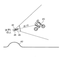
そして本実施形態の第1の特徴は以下の点にある。即ち図3に示すように、仮想カメラ22を移動体20に追従するように移動させると共に、仮想カメラ22を所与の周期、所与の振幅、所与の波形で振動させる。そして、仮想カメラ22の視点位置24、視線方向26において見える画像であって、移動体20やコース40の画像を含む3人称視点での画像を生成して、プレーヤに表示する。この場合、仮想カメラ22を振動させる処理は、図2の仮想カメラ制御部114が行うことになる。
【0029】
図4に本実施形態により生成される画像の一例を示す。本実施形態によれば、仮想カメラ22を振動させることで、図4に示すように、移動体20のみならず、コース40などの背景についても振動させることができるようになる。これにより、3人称視点であっても、コース40の路面状況をよりリアルに反映した画像を生成することができ、プレーヤに与える仮想現実感を格段に向上できる。
【0030】
画面上に移動体20が表示されない1人称視点で画像を生成する場合には、移動体20の位置と仮想カメラ22の位置はほぼ一致する。したがって、移動体20が振動すれば画面も振動することになり、それほど工夫を要せずに路面状況をプレーヤに伝えることができる。
【0031】
しかしながら、画面上に移動体20が表示される3人称視点で画像を生成する場合には、移動体20の位置と仮想カメラ22の位置(視点位置)は一致しない。したがって、移動体20が振動した場合に、仮想カメラ22をどのように制御するかが1つの技術的課題になる。
【0032】
この場合、図5(A)に示すように、仮想カメラ22と移動体20との間の位置関係を完全に固定する手法を採用すると、コース40などの背景は振動しているように見えるが、移動体20については振動しているようには見えなくなる。したがって、この手法によっては、移動体20が凹凸のある路面を走行しているという感覚を、プレーヤに的確に伝えることができない。
【0033】
一方、図5(B)に示すように、仮想カメラ22と移動体20との間の位置関係を完全には固定せず、例えば仮想カメラ22の高さ(地面からの)を固定にする手法を採用すると、移動体20は振動しているように見えるが、コース40などの背景については振動しているようには見えなくなる。そして画面全体の面積に対する移動体20の占める面積は小さいため、移動体20のみが振動していても、凹凸のある路面を走行しているという感覚を今一つプレーヤは感じ取ることができない。
【0034】
このように図5(A)、(B)に示した手法によっては、結局、路面状況が変化している様子をプレーヤに十分に伝えることはできない。
【0035】
これに対して本実施形態では、図3に示すように、移動体20に仮想カメラ22を追従させると共に、移動体20の振動とは無関係に、仮想カメラ22を所与の周期、振幅で振動させている。このため、図4に示すように、移動体20のみならず、コース40などの背景も振動して見えるようになる。したがって、路面状況が変化している様子をプレーヤに十分且つ的確に伝えることができ、プレーヤの感じる仮想現実感を格段に向上できる。
【0036】
また本実施形態の第2の特徴は、移動体20の一部又は全部を、仮想カメラ22の振動とは周期や振幅や波形が異なるように振動させる点にある。即ち、例えば図6に示すように、仮想カメラ22を周期T1、振幅AP1で振動させる一方で、移動体20を周期T2、振幅AP2で振動させる。このようにすることで、移動体20が画面に対して振動しているように見せることができると共に、移動体20が仮想カメラ22に対して振動しているように見せることができるようになる。これにより、路面状況が変化している様子を、更に十分且つ的確にプレーヤに伝えることが可能となる。
【0037】
なお移動体20の全体を振動させるのではなく、移動体20の一部、例えばタイヤ等のみを振動させるようにしてもよい。また振動の周期や振幅を異ならせるのではなく、波形の種類を異ならせるようにしてもよい。
【0038】
また本実施形態の第3の特徴は、所与の条件が成立した場合に、仮想カメラの振動を停止する点にある。例えば図7に示すように、移動体20がジャンプ台42から飛んだ場合(移動体20が地面から離れた場合)に仮想カメラ22の振動を停止する。あるいは、移動体20が転倒した場合等にも仮想カメラ22の振動を停止する。
【0039】
即ち本実施形態では、移動体20の振動とは独立して仮想カメラ22を振動させている。したがって、移動体20が飛んだり転倒し、移動体20自体の振動が停止すべき状況になった場合に、何も処置を施さないと、仮想カメラ22のみが振動してしまい、不自然な画像がプレーヤに表示されてしまう。本実施形態では、このような場合に、仮想カメラ22の振動が停止するため、プレーヤが不自然さを感じるのを有効に防止できるようになる。
【0040】
なお仮想カメラ22の振動を停止させる所与の条件としては、移動体20のジャンプや転倒に限らず、種々の条件を考えることができる。
【0041】
また本実施形態の第3の特徴は、移動体の速度が高くなるにつれて、仮想カメラの振動の周期を短くしたり振幅を大きくする点にある。
【0042】
即ち本実施形態では、図8(A)に示すように、移動体20の速度が高くなるにつれて仮想カメラ22の振動の周期が短くなる。このようにすることで、移動体20の速度が高くなるにつれて路面の上下の揺れの時間間隔が短くなるという感覚を、プレーヤに与えることができる。また本実施形態では、図8(B)に示すように、移動体20の速度が高くなるにつれて仮想カメラ22の振幅が大きくなる。このようにすることで、移動体20の速度が高くなるにつれて路面の上下の揺れの大きさが大きくなるという感覚を、プレーヤに与えることができる。以上のような本実施形態の第3の特徴により、路面状況の変化を、よりリアルにシミュレートすることが可能となり、プレーヤの仮想現実感を更に一層高めることが可能になる。
【0043】
また本実施形態の第4の特徴は、移動体が移動するエリアに応じて、仮想カメラの振動の周期や振幅や波形を変化させる点にある。
【0044】
即ち図9に示すように、コース40には、路面状況の違う複数のエリアが設けられる。そして、移動体20が例えばアスファルトエリア50を走行している場合には、仮想カメラの振動の振幅はほとんど零になる。また移動体20が、岩エリア51を走行している場合には振幅の大きい振動になる。また草エリア52を走行している場合には長い周期で小さな振幅の振動になる。また砂利エリア53を走行している場合には短い周期で小さいな振幅の振動になり、土エリア54を走行している場合には更に短い周期で更に小さな振動になる。
【0045】
このように、仮想カメラの振動の周期や振幅や波形をエリア毎に異ならせることで、路面状況の変化の更にリアルなシミュレートが可能となり、プレーヤの仮想現実感を更に向上できるようになる。
【0046】
なお前述の図4は移動体20が岩エリアを走行している場合の画像の例である。一方、図10に、移動体20が土エリアを走行している場合の画像の例を示す。このように本実施形態では、移動体20が岩エリアや土エリアを走行している場合に、まず、各エリアの路面状況を表す画像を表示することで、岩エリアや土エリアを走行しているという仮想現実感をプレーヤに与えている。そして、更に、各々のエリアの路面の凹凸に対応した波形で移動体20や背景を振動させることで、プレーヤの感じる仮想現実感を更に一層向上させている。
【0047】
さて本実施形態では図11に示すように、コース40を、複数のポリゴンなどのプリミティブ面の組み合わせにより構成している。移動体20は、これらのポリゴンにより構成されたコース40上を走行する。
【0048】
そして本実施形態の第5の特徴は以下の点にある。即ち、コースなどのマップを構成する各ポリゴンに、仮想カメラの振動の周期や振幅や波形を特定するための属性データを持たせる。そして、移動体が位置するポリゴンが有する属性データに基づいて、仮想カメラを振動させる。
【0049】
例えば図12では、コース40はポリゴン56-1〜56-9により構成される。そしてポリゴン56-1〜56-3にはアスファルト路面の振動を特定するための属性データが設定されている。同様にポリゴン56-4〜56-6には岩路面の振動を特定するための属性データが、ポリゴン56-7〜56-9には草路面の振動を特定するための属性データが設定されている。そして、図12では、移動体20はポリゴン56-5の場所に位置している。したがって、この場合には、岩路面の振動を特定するための属性データが読み出され、仮想カメラは、この属性データに基づいて振動する。
【0050】
このように各ポリゴンに設定された属性データに基づいて仮想カメラを振動させることで、路面状況の変化の、より精細な制御が可能となる。即ち、図9の砂利エリア53、土エリア54のように、コース40の左側と右側で路面状況を変えることが可能となる。また左側、中央、右側で路面状況を変えることも可能である。
【0051】
なお以上では、コースを、プリミティブ面の1つであるポリゴンで構成した場合を例にとり説明したが、曲面などの他の形態のプリミティブ面によりコースを構成してもよい。
【0052】
次に本実施形態の詳細な処理例について、図13のフローチャートを用いて説明する。
【0053】
まず図2の移動体演算部112が移動体の位置、方向を算出する(ステップS1)。この算出はフレーム毎に行われる。
【0054】
次に図2の仮想カメラ制御部114が、移動体の位置、方向に基づき仮想カメラの視点位置、視線方向を算出する(ステップS2)。仮想カメラの視点位置は、例えば、移動体の位置からワールド(X、Y、Z)座標系で一定の座標値(△X、△Y、△Z)だけ離れた位置に設定される。また移動体の速度等が急激に変化した場合にも、滑らかに追従できるように、仮想カメラは慣性を持ちながら移動体に追従するようになっている。
【0055】
次に移動体が飛んでいる(地面から離れている)か否かを判断する(ステップS3)。そして図7に示すように移動体が飛んでいる場合には、ステップS5以下の仮想カメラを振動させる処理を省略する。
【0056】
次に移動体が転倒しているか否かを判断する(ステップS4)。そして移動体が転倒している場合には、ステップS5以下の仮想カメラを振動させる処理を省略する。
【0057】
次に移動体が位置する(接触している)ポリゴンを検索し、そのポリゴンの属性データ(仮想カメラの振動を特定するためのデータ)を読み出す(ステップS5)。
【0058】
ここで本実施形態では、移動体が位置するポリゴンを以下のようにして検索している。即ち図14(A)に示すように本実施形態では、コース40を複数のコースブロックC0〜C1000に分割している。コース40は、道のり距離で例えば1m間隔毎にコースブロックに分割される。そして図14(B)において、移動体20がコースブロックCj内に位置するか否かを、ライン60、62の配置データにより判定する。このように移動体20が位置するコースブロックを特定することで、移動体20の順位や時間延長の可否等を決めることができる。また図14(C)に示すように、各コースブロックは複数のポリゴン、例えば三角形のポリゴンに分割されている。本実施形態では、移動体20の位置をコースブロックに設定されるr、s座標系に変換する。そして、このr、s座標系での移動体20の位置に基づいて、移動体20が、どの三角形のポリゴンに位置するかを判別する。以上のようにして、移動体20が位置するポリゴンが検索される。
【0059】
図13の説明に戻る。属性データを読み出した後、波形メモリデータの読み出しアドレスRAを下式(3)にしたがって決める。
RA=MOD(RA+K1×VM,WDL) (3)
ここでMOD(A/B)は、AをBで割った時の剰余を表すものである。またK1は定数であり、VMは移動体の速度であり、WDLは波形データ長である。また読み出しアドレスRAは初期状態では零に設定されている。
【0060】
図15(A)、(B)、(C)に、波形データメモリに記憶される種々の波形データの例を示す。図15(A)はアスファルト路面の振動を表す波形データ、図15(B)は岩路面の振動を表す波形データ、図15(C)は草路面の振動を表す波形データである。すべての波形データのWDLは256で同一になっている。
【0061】
上式(3)から明らかなように、移動体の速度VMが速いほど波形データの再生速度が速くなり、波形の振動の周期が実質的に短くなる。即ち図8(A)に示すように、移動体の速度が高くなればなるほど周期が短くなるように、仮想カメラの振動を制御できるようになる。また上式(3)でRA+K1×VMをWDLで割りその剰余をRAにしているのは、図15(A)、(B)、(C)に示すように波形データメモリには有限の波形データ長の波形データしか記憶されていないからである。
【0062】
次に、ステップS5で読み出された属性データと、ステップS6で得られた読み出しアドレスRAとに基づいて、振幅APが波形データメモリから読み出される(ステップS7)。即ち、どの波形データを参照するかは、図12で説明したように、ステップS5で得られた属性データに基づき選択される。例えば属性データがアスファルト路面を指定するものであれば図15(A)の波形データが、岩路面を指定するものであれば図15(B)の波形データが、草路面を指定するものであれば図15(C)の波形データが参照される。またステップS6で得られた読み出しアドレスRAを指定することで、振幅APを得ることができる。例えば図15(B)でRA=200が指定されると、AP=2000が得られる。
【0063】
次に、下式(4)に示すようにして振幅APを補正する(ステップS8)。
AP=K2×AP×VM (4)
ここでK2は定数である。上式(4)のような補正をすることで、図8(B)に示すように、移動体の速度VMが大きくなるほど振幅APが大きくなるように、仮想カメラの振動を制御することが可能になる。
【0064】
次に、下式(5)に示すようにして、ステップS2で得られた仮想カメラの高さ(視点位置の高さ)HCを補正する(ステップS9)。
HC=HC+AP (5)
以上のようにすることで、各種波形データに応じた振幅、周期、波形で仮想カメラを振動させることが可能になる。
【0065】
次に、本実施形態を実現できるハードウェアの構成の一例について図16を用いて説明する。同図に示す装置では、CPU1000、ROM1002、RAM1004、情報記憶媒体1006、音生成IC1008、画像生成IC1010、I/Oポート1012、1014が、システムバス1016により相互にデータ送受信可能に接続されている。そして前記画像生成IC1010にはディスプレイ1018が接続され、音生成IC1008にはスピーカ1020が接続され、I/Oポート1012にはコントロール装置1022が接続され、I/Oポート1014には通信装置1024が接続されている。
【0066】
情報記憶媒体1006は、プログラム、表示物を表現するための画像データ、音データ等が主に格納されるものである。例えば家庭用ゲーム装置ではゲームプログラム等を格納する情報記憶媒体としてCD−ROM、ゲームカセット、DVD等が用いられる。また業務用ゲーム装置ではROM等のメモリが用いられ、この場合には情報記憶媒体1006はROM1002になる。
【0067】
コントロール装置1022はゲームコントローラ、操作パネル等に相当するものであり、プレーヤがゲーム進行に応じて行う判断の結果を装置本体に入力するための装置である。
【0068】
情報記憶媒体1006に格納されるプログラム、ROM1002に格納されるシステムプログラム(装置本体の初期化情報等)、コントロール装置1022によって入力される信号等に従って、CPU1000は装置全体の制御や各種データ処理を行う。RAM1004はこのCPU1000の作業領域等として用いられる記憶手段であり、情報記憶媒体1006やROM1002の所与の内容、あるいはCPU1000の演算結果等が格納される。また本実施形態を実現するための論理的な構成を持つデータ構造(例えば図15(A)、(B)、(C)の波形データ)は、このRAM又は情報記憶媒体上に構築されることになる。
【0069】
更に、この種の装置には音生成IC1008と画像生成IC1010とが設けられていてゲーム音やゲーム画像の好適な出力が行えるようになっている。音生成IC1008は情報記憶媒体1006やROM1002に記憶される情報に基づいて効果音やバックグラウンド音楽等のゲーム音を生成する集積回路であり、生成されたゲーム音はスピーカ1020によって出力される。また、画像生成IC1010は、RAM1004、ROM1002、情報記憶媒体1006等から送られる画像情報に基づいてディスプレイ1018に出力するための画素情報を生成する集積回路である。なおディスプレイ1018として、いわゆるヘッドマウントディスプレイ(HMD)と呼ばれるものを使用することもできる。
【0070】
また、通信装置1024はゲーム装置内部で利用される各種の情報を外部とやりとりするものであり、他のゲーム装置と接続されてゲームプログラムに応じた所与の情報を送受したり、通信回線を介してゲームプログラム等の情報を送受することなどに利用される。
【0071】
そして図1〜図12、図14(A)〜図15(C)で説明した種々の処理は、図13のフローチャートに示した処理等を行うプログラムを格納した情報記憶媒体1006と、該プログラムに従って動作するCPU1000、画像生成IC1010、音生成IC1008等によって実現される。なお画像生成IC1010、音生成IC1008等で行われる処理は、CPU1000あるいは汎用のDSP等によりソフトウェア的に行ってもよい。
【0072】
さて前述した図1は、本実施形態を業務用ゲーム装置に適用した場合の例を示すものである。この場合、装置に内蔵されるシステム基板1106には、CPU、画像生成IC、音生成IC等が実装されている。そして、オブジェクト空間内で移動体を移動させる演算を行うための情報、仮想カメラを移動体に追従するように移動させると共に、仮想カメラを所与の周期、所与の振幅、所与の波形で振動させるための情報、仮想カメラから見える画像であって、移動体の画像を含む3人称視点での画像を生成するための情報、移動体の一部又は全部を、仮想カメラの振動とは周期、振幅及び波形の少なくとも1つが異なるように振動させるための情報等は、システム基板1106上の情報記憶媒体であるメモリ1108に格納される。以下、これらの情報を格納情報と呼ぶ。これらの格納情報は、上記の種々の処理を行うためのプログラムコード、画像情報、音情報、表示物の形状情報、テーブルデータ、リストデータ、プレーヤ情報等の少なくとも1つを含むものである。
【0073】
図17(A)に、本実施形態を家庭用のゲーム装置に適用した場合の例を示す。プレーヤはディスプレイ1200に映し出されたゲーム画像を見ながら、ゲームコントローラ1202、1204を操作してゲームを楽しむ。この場合、上記格納情報は、本体装置に着脱自在な情報記憶媒体であるCD−ROM1206、ICカード1208、1209等に格納されている。
【0074】
図17(B)に、ホスト装置1300と、このホスト装置1300と通信回線1302を介して接続される端末1304-1〜1304-nとを含むゲーム装置に本実施形態を適用した場合の例を示す。この場合、上記格納情報は、例えばホスト装置1300が制御可能な磁気ディスク装置、磁気テープ装置、メモリ等の情報記憶媒体1306に格納されている。端末1304-1〜1304-nが、CPU、画像生成IC、音生成ICを有し、スタンドアロンでゲーム画像、ゲーム音を生成できるものである場合には、ホスト装置1300からは、ゲーム画像、ゲーム音を生成するためのゲームプログラム等が端末1304-1〜1304-nに配送される。一方、スタンドアロンで生成できない場合には、ホスト装置1300がゲーム画像、ゲーム音を生成し、これを端末1304-1〜1304-nに伝送し端末において出力することになる。
【0075】
なお本発明は、上記実施形態で説明したものに限らず、種々の変形実施が可能である。
【0076】
例えば仮想カメラを振動させる手法は、図13〜図15(C)等を用いて説明した手法が特に望ましいが、これ以外にも種々の変形実施が可能である。
【0077】
また移動体が移動するエリアに応じて、仮想カメラの振動の周期や振幅や波形を変化させる手法は、図9〜図12で説明した手法が特に望ましいが、これ以外にも種々の変形実施が可能である。例えば図14(A)で説明したコースブロックの各々に、振動の周期等を特定するための属性データを設定し、この属性データに基づいて振動の周期等を切り替えてもよい。
【0078】
例えば本実施形態では自転車の競争ゲームに本発明を適用した場合について説明したが、本発明はこれに限らず種々のゲーム(他の競争ゲーム、スポーツゲーム、対戦ゲーム等)に適用できる。
【0079】
また本発明は、家庭用、業務用のゲーム装置のみならず、シミュレータ、多数のプレーヤが参加する大型アトラクション装置、パーソナルコンピュータ、マルチメディア端末、ゲーム画像を生成するシステム基板等の種々の画像生成装置にも適用できる。
【0080】
【図面の簡単な説明】
【図1】本実施形態の画像生成装置の外観図の一例である。
【図2】本実施形態の画像生成装置の機能ブロック図の一例である。
【図3】本実施形態の原理について説明するための図である。
【図4】本実施形態により生成される画像の例を示す図である。
【図5】図5(A)、(B)は仮想カメラの制御に関する種々の手法について説明するための図である。
【図6】仮想カメラの振動の周期等と移動体の振動の周期等を異ならせる手法について説明するための図である。
【図7】移動体が飛んだ場合に仮想カメラの振動を停止する手法について説明するための図である。
【図8】図8(A)、(B)は、移動体の速度に応じて仮想カメラの振動の周期や振幅を変化させる手法について説明するための図である。
【図9】エリア毎に仮想カメラの振動の周期等を異ならせる手法について説明するための図である。
【図10】本実施形態により生成される画像の例を示す図である。
【図11】複数のポリゴンにより構成されるコースの例を示す図である。
【図12】各ポリゴンへの属性データの設定について説明するための図である。
【図13】本実施形態の詳細な処理例を説明するためのフローチャートである。
【図14】図14(A)、(B)、(C)は、コースブロックについて説明するための図である。
【図15】図15(A)、(B)、(C)は各種の波形データの例について説明するための図である。
【図16】本実施形態を実現できるハードウェアの構成の一例を示す図である。
【図17】図17(A)、(B)は、本実施形態が適用される種々の形態の装置の例を示す図である。
【符号の説明】
10 操作部
12 表示部
16 ライディング筐体
17 サドル
18 ディスプレイ
20 移動体(自転車)
22 仮想カメラ
24 視点位置
26 視線方向
30 ペダル
32 ハンドル
40 コース
100 処理部
110 ゲーム演算部
112 移動体演算部
114 仮想カメラ制御部
150 画像生成部
190 情報記憶媒体[0001]
BACKGROUND OF THE INVENTION
The present invention relates to an image generation apparatus and an information storage medium that generate an image at a given viewpoint in an object space.
[0002]
[Background Art and Problems to be Solved by the Invention]
2. Description of the Related Art Conventionally, image generation apparatuses that arrange a plurality of objects in an object space that is a virtual three-dimensional space and generate an image that can be viewed from a given viewpoint in the object space have been developed and put into practical use. It is popular as a way to experience reality. Taking an image generation apparatus that can enjoy a racing car game as an example, a player enjoys a three-dimensional game by running a moving body such as a car that the user operates in the object space.
[0003]
Now, with such an image generation device, there is a problem of improving the virtual reality of the player. For this purpose, it is desired to generate a realistic image reflecting the road surface condition and the like.
[0004]
However, with conventional image generation apparatuses, when a moving object generates an image from a third-person viewpoint displayed on the screen, it is impossible for the player to feel the rattling of the road surface or the change of the road surface. was there.
[0005]
The present invention has been made in view of the above problems, and an object of the present invention is to provide an image generation apparatus and an information storage medium capable of generating a real image reflecting road surface conditions and the like. .
[0006]
[Means for Solving the Problems]
In order to solve the above-described problems, the present invention provides an image generation apparatus that generates an image at a given viewpoint in an object space, a unit that performs an operation of moving a moving object in the object space, and a virtual camera And a means for vibrating the virtual camera at a given period, a given amplitude, and a given waveform, and an image visible from the virtual camera, the moving body And a means for generating an image from a third-person viewpoint including the above-mentioned image.
[0007]
According to the present invention, an image at a third-person viewpoint from a virtual camera that moves so as to follow a moving object is generated. The virtual camera vibrates with a given period, amplitude, and waveform independently of the vibration of the moving body, for example. In this way, it is possible to generate an image that appears to vibrate not only for a moving object but also for a background such as a course. As a result, a realistic image reflecting the road surface condition and the like can be provided, and the virtual reality can be improved.
[0008]
According to the present invention, part or all of the moving body is vibrated so that at least one of a period, an amplitude, and a waveform is different from the vibration of the virtual camera. By doing so, the virtual camera and the moving body vibrate independently at different periods or the like. This makes it possible to reliably generate an image that makes the moving body appear to vibrate.
[0009]
Further, the present invention is characterized in that the vibration of the virtual camera is stopped when a given condition is satisfied. By doing in this way, the situation where an unnatural image is displayed can be prevented.
[0010]
In this case, it is desirable to stop the vibration of the virtual camera in at least one of the case where the moving body is flying and the case where the moving body is falling.
[0011]
Further, the invention is characterized in that the vibration period of the virtual camera is shortened as the speed of the moving body increases. By doing so, it is possible to give the player a feeling that the time interval such as up and down swings becomes shorter as the speed of the moving body increases.
[0012]
The present invention is characterized in that the amplitude of vibration of the virtual camera is increased as the speed of the moving body increases. By doing so, it becomes possible to give the player a feeling that the magnitude of the up and down shaking or the like increases as the speed of the moving body increases.
[0013]
In the invention, it is preferable that at least one of a vibration period, an amplitude, and a waveform of the virtual camera is changed according to an area in which the moving body moves. By doing so, it becomes possible to increase the variety of running feeling given to the player, and to improve the virtual reality of the player.
[0014]
Further, according to the present invention, attribute data for specifying at least one of a vibration period, an amplitude, and a waveform of the virtual camera is provided on each primitive surface constituting a map in which the moving body moves, and the moving body is positioned. The virtual camera is vibrated based on attribute data of the primitive surface. By doing in this way, it becomes possible to control the change of a road surface condition more finely.
[0015]
DETAILED DESCRIPTION OF THE INVENTION
Hereinafter, preferred embodiments of the present invention will be described with reference to the drawings. In the following, a case where the present invention is applied to a bicycle game will be described as an example. However, the present invention is not limited to this.
[0016]
FIG. 1 shows an example of an external view when the image generation apparatus of the present embodiment is applied to a business game apparatus.
[0017]
Here, the
[0018]
FIG. 2 shows an example of a functional block diagram of the image generation apparatus of the present embodiment.
[0019]
Here, the
[0020]
The
[0021]
The
[0022]
The
[0023]
Here, the
[0024]
The
[0025]
The
[0026]
Here, the moving object calculation unit 112 selects a moving object operated by the player or a moving object whose movement is controlled by a given control program (computer) based on operation data input from the
[0027]
For example, assume that the position of the moving body in the (k-1) frame is PMk-1, the speed is VMk-1, the acceleration is AMk-1, and the time of one frame is Δt. Then, the position PMk and the speed VMk of the moving body in k frames are obtained, for example, by the following equations (1) and (2).
PMk = PMk-1 + VMk-1 * .DELTA.t (1)
VMk = VMk-1 + AMk-1 * .DELTA.t (2)
The virtual camera control unit 114 performs a calculation for controlling the viewpoint position and the line-of-sight direction of the virtual camera based on the position and direction data of the moving body obtained by the moving body calculation unit 112. More specifically, the viewpoint position and line-of-sight direction of the virtual camera are controlled so as to follow the moving body operated by the player while having inertia, for example. The
[0028]
The first feature of the present embodiment is as follows. That is, as shown in FIG. 3, the
[0029]
FIG. 4 shows an example of an image generated by this embodiment. According to the present embodiment, by vibrating the
[0030]
When an image is generated from a first-person viewpoint where the moving
[0031]
However, when an image is generated from a third-person viewpoint where the moving
[0032]
In this case, as shown in FIG. 5A, when a method of completely fixing the positional relationship between the
[0033]
On the other hand, as shown in FIG. 5B, the positional relationship between the
[0034]
As described above, according to the methods shown in FIGS. 5A and 5B, it is impossible to sufficiently tell the player that the road surface condition is changing.
[0035]
In contrast, in the present embodiment, as shown in FIG. 3, the
[0036]
The second feature of the present embodiment is that part or all of the moving
[0037]
Instead of vibrating the entire moving
[0038]
The third feature of the present embodiment is that the vibration of the virtual camera is stopped when a given condition is satisfied. For example, as shown in FIG. 7, when the moving
[0039]
That is, in this embodiment, the
[0040]
The given condition for stopping the vibration of the
[0041]
A third feature of the present embodiment is that the vibration period of the virtual camera is shortened or the amplitude is increased as the speed of the moving body increases.
[0042]
That is, in this embodiment, as shown in FIG. 8A, the vibration cycle of the
[0043]
The fourth feature of the present embodiment is that the vibration period, amplitude, and waveform of the virtual camera are changed according to the area in which the moving body moves.
[0044]
That is, as shown in FIG. 9, the
[0045]
As described above, by changing the vibration period, amplitude, and waveform of the virtual camera for each area, it is possible to simulate a more realistic change in the road surface condition and further improve the virtual reality of the player.
[0046]
Note that FIG. 4 described above is an example of an image when the moving
[0047]
In the present embodiment, as shown in FIG. 11, the
[0048]
The fifth feature of the present embodiment is as follows. That is, each polygon constituting the map such as a course is provided with attribute data for specifying the vibration period, amplitude, and waveform of the virtual camera. Then, the virtual camera is vibrated based on the attribute data of the polygon where the moving body is located.
[0049]
For example, in FIG. 12, the
[0050]
In this way, by vibrating the virtual camera based on the attribute data set for each polygon, it becomes possible to perform finer control of changes in road surface conditions. That is, the road surface condition can be changed between the left side and the right side of the
[0051]
In the above description, the case where the course is configured by a polygon that is one of the primitive surfaces has been described as an example. However, the course may be configured by other forms of primitive surfaces such as a curved surface.
[0052]
Next, a detailed processing example of this embodiment will be described with reference to the flowchart of FIG.
[0053]
First, the moving object calculation unit 112 in FIG. 2 calculates the position and direction of the moving object (step S1). This calculation is performed for each frame.
[0054]
Next, the virtual camera control unit 114 in FIG. 2 calculates the viewpoint position and line-of-sight direction of the virtual camera based on the position and direction of the moving object (step S2). The viewpoint position of the virtual camera is set, for example, at a position away from the position of the moving body by a fixed coordinate value (ΔX, ΔY, ΔZ) in the world (X, Y, Z) coordinate system. In addition, the virtual camera follows the moving body with inertia so that it can smoothly follow even when the speed of the moving body changes rapidly.
[0055]
Next, it is determined whether or not the moving body is flying (away from the ground) (step S3). Then, when the moving body is flying as shown in FIG. 7, the process of vibrating the virtual camera in step S5 and subsequent steps is omitted.
[0056]
Next, it is determined whether or not the moving body is overturned (step S4). If the moving body is falling, the process of vibrating the virtual camera in step S5 and subsequent steps is omitted.
[0057]
Next, the polygon where the moving body is located (contacted) is searched, and attribute data of the polygon (data for specifying the vibration of the virtual camera) is read (step S5).
[0058]
Here, in the present embodiment, the polygon where the moving body is located is searched as follows. That is, as shown in FIG. 14A, in this embodiment, the
[0059]
Returning to the description of FIG. After reading the attribute data, the waveform memory data read address RA is determined according to the following equation (3).
RA = MOD (RA + K1 × VM, WDL) (3)
Here, MOD (A / B) represents the remainder when A is divided by B. K1 is a constant, VM is the speed of the moving object, and WDL is the waveform data length. The read address RA is set to zero in the initial state.
[0060]
15A, 15B, and 15C show examples of various waveform data stored in the waveform data memory. FIG. 15A shows waveform data representing the vibration of the asphalt road surface, FIG. 15B shows the waveform data representing the vibration of the rock road surface, and FIG. 15C shows the waveform data representing the vibration of the grass road surface. The WDL of all waveform data is the same at 256.
[0061]
As is clear from the above equation (3), the faster the moving object speed VM, the faster the waveform data reproduction speed, and the shorter the waveform oscillation period. That is, as shown in FIG. 8A, the vibration of the virtual camera can be controlled so that the cycle becomes shorter as the speed of the moving body becomes higher. Also, RA + K1 × VM is divided by WDL in the above equation (3) and the remainder is set to RA as shown in FIGS. 15A, 15B, and 15C. The waveform data memory has finite waveform data. This is because only long waveform data is stored.
[0062]
Next, the amplitude AP is read from the waveform data memory based on the attribute data read in step S5 and the read address RA obtained in step S6 (step S7). That is, which waveform data is to be referred to is selected based on the attribute data obtained in step S5 as described with reference to FIG. For example, if the attribute data designates an asphalt road surface, the waveform data in FIG. 15A designates a rocky road surface. If the attribute data designates a rock road surface, the waveform data in FIG. 15B designates a grass road surface. For example, the waveform data in FIG. Also, the amplitude AP can be obtained by designating the read address RA obtained in step S6. For example, when RA = 200 is designated in FIG. 15B, AP = 2000 is obtained.
[0063]
Next, the amplitude AP is corrected as shown in the following equation (4) (step S8).
AP = K2 × AP × VM (4)
Here, K2 is a constant. By correcting the above equation (4), it is possible to control the vibration of the virtual camera so that the amplitude AP increases as the velocity VM of the moving object increases as shown in FIG. 8B. become.
[0064]
Next, as shown in the following equation (5), the height (the height of the viewpoint position) HC of the virtual camera obtained in step S2 is corrected (step S9).
HC = HC + AP (5)
By doing as described above, the virtual camera can be vibrated with the amplitude, period, and waveform corresponding to various waveform data.
[0065]
Next, an example of a hardware configuration capable of realizing the present embodiment will be described with reference to FIG. In the apparatus shown in the figure, a
[0066]
The
[0067]
The
[0068]
In accordance with a program stored in the
[0069]
Further, this type of apparatus is provided with a
[0070]
The
[0071]
Various processes described with reference to FIGS. 1 to 12 and FIGS. 14A to 15C are performed in accordance with an
[0072]
FIG. 1 described above shows an example in which the present embodiment is applied to an arcade game machine. In this case, a CPU, an image generation IC, a sound generation IC, and the like are mounted on a
[0073]
FIG. 17A shows an example in which the present embodiment is applied to a home game device. The player enjoys the game by operating the
[0074]
FIG. 17B shows an example in which the present embodiment is applied to a game device including a
[0075]
The present invention is not limited to that described in the above embodiment, and various modifications can be made.
[0076]
For example, as the method for vibrating the virtual camera, the method described with reference to FIGS. 13 to 15C and the like is particularly desirable, but various other modifications are possible.
[0077]
The method described with reference to FIGS. 9 to 12 is particularly preferable as a method of changing the vibration period, amplitude, and waveform of the virtual camera in accordance with the area in which the moving body moves. Is possible. For example, attribute data for specifying the vibration period and the like may be set in each of the course blocks described with reference to FIG. 14A, and the vibration period and the like may be switched based on the attribute data.
[0078]
For example, in the present embodiment, the case where the present invention is applied to a bicycle competition game has been described. However, the present invention is not limited to this and can be applied to various games (other competition games, sports games, battle games, etc.).
[0079]
The present invention is not limited to home and business game devices, but also various image generation devices such as a simulator, a large attraction device in which a large number of players participate, a personal computer, a multimedia terminal, and a system board for generating game images. It can also be applied to.
[0080]
[Brief description of the drawings]
FIG. 1 is an example of an external view of an image generation apparatus according to an embodiment.
FIG. 2 is an example of a functional block diagram of the image generation apparatus of the present embodiment.
FIG. 3 is a diagram for explaining the principle of the present embodiment;
FIG. 4 is a diagram illustrating an example of an image generated according to the present embodiment.
FIGS. 5A and 5B are diagrams for explaining various methods related to control of a virtual camera. FIGS.
FIG. 6 is a diagram for explaining a method of making a vibration period of a virtual camera different from a vibration period of a moving body.
FIG. 7 is a diagram for explaining a method for stopping vibration of a virtual camera when a moving object flies.
FIGS. 8A and 8B are diagrams for describing a method of changing the vibration period and amplitude of a virtual camera in accordance with the speed of a moving object.
FIG. 9 is a diagram for explaining a method of changing a virtual camera vibration period and the like for each area;
FIG. 10 is a diagram illustrating an example of an image generated according to the present embodiment.
FIG. 11 is a diagram showing an example of a course composed of a plurality of polygons.
FIG. 12 is a diagram for describing setting of attribute data for each polygon;
FIG. 13 is a flowchart for explaining a detailed processing example of the present embodiment;
FIGS. 14A, 14B, and 14C are diagrams for explaining a course block. FIG.
FIGS. 15A, 15B, and 15C are diagrams for explaining examples of various waveform data. FIGS.
FIG. 16 is a diagram illustrating an example of a hardware configuration capable of realizing the present embodiment.
FIGS. 17A and 17B are diagrams illustrating examples of various types of apparatuses to which the present embodiment is applied.
[Explanation of symbols]
DESCRIPTION OF
22
Claims (4)
複数のプリミティブ面が配置されたオブジェクト空間内で移動体を移動させる演算を行う移動体演算手段と、
仮想カメラを前記移動体に追従するように移動させると共に、所与の再生速度で順次読み出される波形データに基づいて前記仮想カメラを振動させる仮想カメラ制御手段と、
前記仮想カメラから見える画像であって、前記移動体の画像を含む3人称視点での画像を生成する画像生成手段とを含み、
前記オブジェクト空間には、前記複数のプリミティブ面が凹凸を成すように配置され、
前記移動体演算手段は、
前記複数のプリミティブ面が成す凹凸に応じて前記移動体の位置を変動させることによって前記移動体を振動させ、
前記仮想カメラ制御手段が、
前記移動体に追従するように移動させた前記仮想カメラの位置を、前記移動体が位置するプリミティブ面の属性に応じて補正することによって、前記仮想カメラを振動させ、当該仮想カメラを振動させる際に、複数種類の波形データから前記移動体が位置するプリミティブ面の属性に応じた波形データを選択し、選択された波形データに基づいて、前記複数のプリミティブ面が成す凹凸に応じた前記移動体の振動に関わらず前記仮想カメラを振動させることを特徴とする画像生成装置。An image generation device that generates an image at a given viewpoint in an object space,
A moving object computing means for performing an operation of moving the moving object in an object space in which a plurality of primitive surfaces are arranged;
Virtual camera control means for moving the virtual camera to follow the moving body and vibrating the virtual camera based on waveform data sequentially read at a given playback speed ;
An image generation unit that generates an image viewed from the virtual camera, and that generates an image from a third-person viewpoint including the image of the moving object;
In the object space, the plurality of primitive surfaces are arranged so as to form irregularities,
The moving body computing means includes
Vibrating the moving body by changing the position of the moving body according to the irregularities formed by the plurality of primitive surfaces,
The virtual camera control means is
The position of the virtual camera is moved to follow the moving object, by correcting depending on the attributes of the primitive surface the movable body is positioned, wherein the virtual camera is vibrated, when vibrating the virtual camera In addition, the waveform data corresponding to the attribute of the primitive surface on which the moving body is located is selected from a plurality of types of waveform data, and the moving body corresponding to the unevenness formed by the plurality of primitive surfaces is selected based on the selected waveform data. An image generating apparatus that vibrates the virtual camera regardless of vibrations .
前記仮想カメラ制御手段は、
前記移動体の速度が高くなるにつれて前記波形データの再生速度を速めることによって、前記仮想カメラの振動の周期を短くすることを特徴とする画像生成装置。In claim 1 ,
The virtual camera control means includes
An image generating apparatus characterized by shortening the period of vibration of the virtual camera by increasing the reproduction speed of the waveform data as the speed of the moving body increases.
前記仮想カメラ制御手段は、
前記移動体の速度が高くなるにつれて、前記仮想カメラの振動の振幅を大きくすることを特徴とする画像生成装置。In claim 1 or 2 ,
The virtual camera control means includes
An image generating apparatus characterized by increasing the amplitude of vibration of the virtual camera as the speed of the moving body increases.
複数のプリミティブ面が配置されたオブジェクト空間内で移動体を移動させる演算を行う移動体演算手段と、
仮想カメラを前記移動体に追従するように移動させると共に、所与の再生速度で順次読み出される波形データに基づいて前記仮想カメラを振動させる仮想カメラ制御手段と、
前記仮想カメラから見える画像であって、前記移動体の画像を含む3人称視点での画像を生成する画像生成手段としてコンピュータを機能させ、
前記オブジェクト空間には、前記複数のプリミティブ面が凹凸を成すように配置され、
前記移動体演算手段は、
前記複数のプリミティブ面が成す凹凸に応じて前記移動体の位置を変動させることによって前記移動体を振動させ、
前記仮想カメラ制御手段が、
前記移動体に追従するように移動させた前記仮想カメラの位置を、前記移動体が位置するプリミティブ面の属性に応じて補正することによって、前記仮想カメラを振動させ、当該仮想カメラを振動させる際に、複数種類の波形データから前記移動体が位置するプリミティブ面の属性に応じた波形データを選択し、選択された波形データに基づいて、前記複数のプリミティブ面が成す凹凸に応じた前記移動体の振動に関わらず前記仮想カメラを振動させるプログラムを記憶した情報記憶媒体。A computer-readable information storage medium for generating an image at a given viewpoint in an object space,
A moving object computing means for performing an operation of moving the moving object in an object space in which a plurality of primitive surfaces are arranged;
Virtual camera control means for moving the virtual camera to follow the moving body and vibrating the virtual camera based on waveform data sequentially read at a given playback speed ;
An image that is visible from the virtual camera and that functions as a computer as an image generation unit that generates an image from a third-person viewpoint including the image of the moving object,
In the object space, the plurality of primitive surfaces are arranged so as to form irregularities,
The moving body computing means includes
Vibrating the moving body by changing the position of the moving body according to the irregularities formed by the plurality of primitive surfaces,
The virtual camera control means is
The position of the virtual camera is moved to follow the moving object, by correcting depending on the attributes of the primitive surface the movable body is positioned, wherein the virtual camera is vibrated, when vibrating the virtual camera In addition, the waveform data corresponding to the attribute of the primitive surface on which the moving body is located is selected from a plurality of types of waveform data, and the moving body corresponding to the unevenness formed by the plurality of primitive surfaces is selected based on the selected waveform data. An information storage medium storing a program for vibrating the virtual camera regardless of vibration .
Priority Applications (1)
| Application Number | Priority Date | Filing Date | Title |
|---|---|---|---|
| JP35213897A JP4114822B2 (en) | 1997-12-05 | 1997-12-05 | Image generating apparatus and information storage medium |
Applications Claiming Priority (1)
| Application Number | Priority Date | Filing Date | Title |
|---|---|---|---|
| JP35213897A JP4114822B2 (en) | 1997-12-05 | 1997-12-05 | Image generating apparatus and information storage medium |
Related Child Applications (1)
| Application Number | Title | Priority Date | Filing Date |
|---|---|---|---|
| JP2007263247A Division JP4397410B2 (en) | 2007-10-09 | 2007-10-09 | Image generating apparatus and information storage medium |
Publications (2)
| Publication Number | Publication Date |
|---|---|
| JPH11175766A JPH11175766A (en) | 1999-07-02 |
| JP4114822B2 true JP4114822B2 (en) | 2008-07-09 |
Family
ID=18422041
Family Applications (1)
| Application Number | Title | Priority Date | Filing Date |
|---|---|---|---|
| JP35213897A Expired - Lifetime JP4114822B2 (en) | 1997-12-05 | 1997-12-05 | Image generating apparatus and information storage medium |
Country Status (1)
| Country | Link |
|---|---|
| JP (1) | JP4114822B2 (en) |
Cited By (1)
| Publication number | Priority date | Publication date | Assignee | Title |
|---|---|---|---|---|
| JPH0676701U (en) * | 1993-04-02 | 1994-10-28 | 住友エール株式会社 | Forklift oil tank drain plug |
Families Citing this family (10)
| Publication number | Priority date | Publication date | Assignee | Title |
|---|---|---|---|---|
| JP4040609B2 (en) * | 2004-07-14 | 2008-01-30 | 株式会社テクノブレイン | Moving body simulation apparatus and moving body simulation program |
| JP2007066291A (en) * | 2005-08-02 | 2007-03-15 | Seiko Epson Corp | Method, apparatus and system for image display, server, program, and recording medium |
| JP2007143684A (en) * | 2005-11-25 | 2007-06-14 | Konami Digital Entertainment:Kk | Game device, method of processing image for game, and program |
| JP2007159817A (en) * | 2005-12-14 | 2007-06-28 | Konami Digital Entertainment:Kk | Game program, game device and game method |
| JP4818810B2 (en) * | 2006-05-24 | 2011-11-16 | 株式会社ユニバーサルエンターテインメント | Game machine |
| JP5969531B2 (en) * | 2014-04-03 | 2016-08-17 | 株式会社スクウェア・エニックス | Image processing program, image processing apparatus, and image processing method |
| JP6837921B2 (en) * | 2017-06-02 | 2021-03-03 | 任天堂株式会社 | Game programs, information processing devices, information processing systems, and information processing methods |
| JP6499728B2 (en) * | 2017-07-18 | 2019-04-10 | 株式会社カプコン | Game program and game system |
| JP7319786B2 (en) * | 2019-02-19 | 2023-08-02 | 株式会社コーエーテクモゲームス | Game program, recording medium, game processing method |
| CN117122902B (en) * | 2023-10-25 | 2024-02-09 | 腾讯科技(深圳)有限公司 | Vibration interaction method, device, equipment and storage medium |
-
1997
- 1997-12-05 JP JP35213897A patent/JP4114822B2/en not_active Expired - Lifetime
Cited By (1)
| Publication number | Priority date | Publication date | Assignee | Title |
|---|---|---|---|---|
| JPH0676701U (en) * | 1993-04-02 | 1994-10-28 | 住友エール株式会社 | Forklift oil tank drain plug |
Also Published As
| Publication number | Publication date |
|---|---|
| JPH11175766A (en) | 1999-07-02 |
Similar Documents
| Publication | Publication Date | Title |
|---|---|---|
| WO1996036017A1 (en) | Image processing apparatus and image processing method | |
| JP2010022646A (en) | Program, information storage medium, and image generation system | |
| JP4114822B2 (en) | Image generating apparatus and information storage medium | |
| JP2001321562A (en) | Game system and information recording medium | |
| JP4397410B2 (en) | Image generating apparatus and information storage medium | |
| JP4056021B2 (en) | Image generating apparatus and information storage medium | |
| JPH11146978A (en) | Three-dimensional game unit, and information recording medium | |
| US20050014561A1 (en) | Simulator, method of controlling simulator, program, and information storage medium | |
| JP4223139B2 (en) | Image generating apparatus and information storage medium | |
| JP3844396B2 (en) | GAME DEVICE AND INFORMATION STORAGE MEDIUM | |
| JP3527578B2 (en) | Game device | |
| JP4212015B2 (en) | Image generating apparatus and information storage medium | |
| JP3138448B2 (en) | Image generation device and information storage medium | |
| JP3753338B2 (en) | 3D simulator apparatus and image composition method | |
| JP3127137B2 (en) | Image generation device and information storage medium | |
| JP2001273525A (en) | Entertainment device, storage medium, and object display method | |
| JP4036508B2 (en) | Image generating apparatus and information storage medium | |
| JP4036509B2 (en) | Image generating apparatus and information storage medium | |
| JPH10165645A (en) | Three dimensional game device and image recording medium | |
| JP4233065B2 (en) | GAME DEVICE AND INFORMATION STORAGE MEDIUM | |
| JP2007181713A (en) | Game machine and information storage medium | |
| JP4560532B2 (en) | Image generating apparatus and information storage medium | |
| JP4108167B2 (en) | Image generating apparatus and information storage medium | |
| JP4042926B2 (en) | Image generating apparatus and information storage medium | |
| JP4251657B2 (en) | Image generating apparatus and information storage medium |
Legal Events
| Date | Code | Title | Description |
|---|---|---|---|
| A521 | Written amendment |
Free format text: JAPANESE INTERMEDIATE CODE: A523 Effective date: 20041203 |
|
| A621 | Written request for application examination |
Free format text: JAPANESE INTERMEDIATE CODE: A621 Effective date: 20041203 |
|
| A977 | Report on retrieval |
Free format text: JAPANESE INTERMEDIATE CODE: A971007 Effective date: 20070802 |
|
| A131 | Notification of reasons for refusal |
Free format text: JAPANESE INTERMEDIATE CODE: A131 Effective date: 20070808 |
|
| A521 | Written amendment |
Free format text: JAPANESE INTERMEDIATE CODE: A523 Effective date: 20071009 |
|
| A02 | Decision of refusal |
Free format text: JAPANESE INTERMEDIATE CODE: A02 Effective date: 20071128 |
|
| A521 | Written amendment |
Free format text: JAPANESE INTERMEDIATE CODE: A523 Effective date: 20080128 |
|
| A911 | Transfer of reconsideration by examiner before appeal (zenchi) |
Free format text: JAPANESE INTERMEDIATE CODE: A911 Effective date: 20080312 |
|
| TRDD | Decision of grant or rejection written | ||
| A01 | Written decision to grant a patent or to grant a registration (utility model) |
Free format text: JAPANESE INTERMEDIATE CODE: A01 Effective date: 20080409 |
|
| A61 | First payment of annual fees (during grant procedure) |
Free format text: JAPANESE INTERMEDIATE CODE: A61 Effective date: 20080411 |
|
| FPAY | Renewal fee payment (event date is renewal date of database) |
Free format text: PAYMENT UNTIL: 20110425 Year of fee payment: 3 |
|
| R150 | Certificate of patent or registration of utility model |
Free format text: JAPANESE INTERMEDIATE CODE: R150 |
|
| FPAY | Renewal fee payment (event date is renewal date of database) |
Free format text: PAYMENT UNTIL: 20110425 Year of fee payment: 3 |
|
| FPAY | Renewal fee payment (event date is renewal date of database) |
Free format text: PAYMENT UNTIL: 20110425 Year of fee payment: 3 |
|
| FPAY | Renewal fee payment (event date is renewal date of database) |
Free format text: PAYMENT UNTIL: 20110425 Year of fee payment: 3 |
|
| FPAY | Renewal fee payment (event date is renewal date of database) |
Free format text: PAYMENT UNTIL: 20120425 Year of fee payment: 4 |
|
| FPAY | Renewal fee payment (event date is renewal date of database) |
Free format text: PAYMENT UNTIL: 20130425 Year of fee payment: 5 |
|
| FPAY | Renewal fee payment (event date is renewal date of database) |
Free format text: PAYMENT UNTIL: 20130425 Year of fee payment: 5 |
|
| FPAY | Renewal fee payment (event date is renewal date of database) |
Free format text: PAYMENT UNTIL: 20140425 Year of fee payment: 6 |
|
| R250 | Receipt of annual fees |
Free format text: JAPANESE INTERMEDIATE CODE: R250 |
|
| R250 | Receipt of annual fees |
Free format text: JAPANESE INTERMEDIATE CODE: R250 |
|
| S531 | Written request for registration of change of domicile |
Free format text: JAPANESE INTERMEDIATE CODE: R313531 |
|
| R360 | Written notification for declining of transfer of rights |
Free format text: JAPANESE INTERMEDIATE CODE: R360 |
|
| S533 | Written request for registration of change of name |
Free format text: JAPANESE INTERMEDIATE CODE: R313533 |
|
| R370 | Written measure of declining of transfer procedure |
Free format text: JAPANESE INTERMEDIATE CODE: R370 |
|
| R350 | Written notification of registration of transfer |
Free format text: JAPANESE INTERMEDIATE CODE: R350 |
|
| S531 | Written request for registration of change of domicile |
Free format text: JAPANESE INTERMEDIATE CODE: R313531 |
|
| R350 | Written notification of registration of transfer |
Free format text: JAPANESE INTERMEDIATE CODE: R350 |
|
| R250 | Receipt of annual fees |
Free format text: JAPANESE INTERMEDIATE CODE: R250 |
|
| EXPY | Cancellation because of completion of term |