JP4111958B2 - Cable protection guide device - Google Patents
Cable protection guide device Download PDFInfo
- Publication number
- JP4111958B2 JP4111958B2 JP2005068498A JP2005068498A JP4111958B2 JP 4111958 B2 JP4111958 B2 JP 4111958B2 JP 2005068498 A JP2005068498 A JP 2005068498A JP 2005068498 A JP2005068498 A JP 2005068498A JP 4111958 B2 JP4111958 B2 JP 4111958B2
- Authority
- JP
- Japan
- Prior art keywords
- side plate
- bent
- plate portion
- bending
- posture
- Prior art date
- Legal status (The legal status is an assumption and is not a legal conclusion. Google has not performed a legal analysis and makes no representation as to the accuracy of the status listed.)
- Active
Links
Images


Classifications
-
- F—MECHANICAL ENGINEERING; LIGHTING; HEATING; WEAPONS; BLASTING
- F16—ENGINEERING ELEMENTS AND UNITS; GENERAL MEASURES FOR PRODUCING AND MAINTAINING EFFECTIVE FUNCTIONING OF MACHINES OR INSTALLATIONS; THERMAL INSULATION IN GENERAL
- F16G—BELTS, CABLES, OR ROPES, PREDOMINANTLY USED FOR DRIVING PURPOSES; CHAINS; FITTINGS PREDOMINANTLY USED THEREFOR
- F16G13/00—Chains
- F16G13/12—Hauling- or hoisting-chains so called ornamental chains
- F16G13/16—Hauling- or hoisting-chains so called ornamental chains with arrangements for holding electric cables, hoses, or the like
-
- H—ELECTRICITY
- H02—GENERATION; CONVERSION OR DISTRIBUTION OF ELECTRIC POWER
- H02G—INSTALLATION OF ELECTRIC CABLES OR LINES, OR OF COMBINED OPTICAL AND ELECTRIC CABLES OR LINES
- H02G11/00—Arrangements of electric cables or lines between relatively-movable parts
- H02G11/006—Arrangements of electric cables or lines between relatively-movable parts using extensible carrier for the cable, e.g. self-coiling spring
Landscapes
- Engineering & Computer Science (AREA)
- General Engineering & Computer Science (AREA)
- Mechanical Engineering (AREA)
- Electric Cable Arrangement Between Relatively Moving Parts (AREA)
- Details Of Indoor Wiring (AREA)
- Professional, Industrial, Or Sporting Protective Garments (AREA)
- Installation Of Indoor Wiring (AREA)
Description
本発明は、ケーブル類保護案内装置に係り、更に詳しくは、産業用機械の可動部材に電力や圧縮空気のエネルギーを供給するケーブルやホース等のケーブル類を収容すると共に、可動部の移動中においてもケーブル類を安全にかつ確実に案内保護するのに好適なケーブル類保護案内装置に関するものである。 The present invention relates to a cable protection guide device, and more particularly, to accommodate cables such as cables and hoses that supply power and compressed air energy to movable members of industrial machines, and during movement of movable parts. The present invention also relates to a cable protection guide apparatus suitable for guiding and protecting cables safely and reliably.
従来のケーブル類保護案内装置として、側板とは別体の継手要素で側板を相互に連結するエネルギー案内チェーンが知られている(例えば、特許文献1参照)。 As a conventional cable protection guide device, an energy guide chain is known in which side plates are connected to each other by joint elements separate from the side plates (see, for example, Patent Document 1).
また、従来のケーブル類保護案内装置として、各側板に一体に形成されている連結杆と連結用溝とを側板間で嵌合することにより側板を相互に連結するケーブル類の保護案内ガイドも知られている(例えば、特許文献2参照)。
ところが、特許文献1のようなエネルギー案内チェーンでは、側板と継手要素とを別体で形成していることにより、多大な部品製作負担や組立作業負担を要するという問題があった。
また、特許文献1のようなエネルギー案内チェーンでは、側板と継手要素を別体で形成していることにより、側板の相互切り継ぎに多大な手間がかかるという保守メンテナンス上の厄介な問題があった。
さらに、特許文献1のエネルギー案内チェーンでは、側板間にそれら側板とは別体の継手要素を嵌め合わせて側板を相互に連結しているので、リンク間の屈曲動作の繰り返しにより、側板と連結部材との間に徐々にズレを生じ、このような側板の継ぎ手部における外れによりチェーンが分解して破損する虞れがあるという問題があった。
However, the energy guide chain as in Patent Document 1 has a problem that a large part manufacturing burden and assembly work burden are required because the side plate and the joint element are formed separately.
Moreover, in the energy guide chain like patent document 1, since the side plate and the joint element are formed separately, there is a troublesome problem in maintenance and maintenance that a large amount of time is required for mutual cutting of the side plates. .
Further, in the energy guide chain of Patent Document 1, since the side plates are connected to each other by fitting joint elements separate from the side plates between the side plates, the side plate and the connecting member are repeatedly formed by repeating the bending operation between the links. There is a problem in that there is a possibility that the chain is disassembled and broken due to such a slippage in the joint portion of the side plate.
他方、特許文献2のようなケーブル類の保護案内ガイドでは、側板の側縁の外側に突出して形成されている連結杆が、リンク体相互を屈曲自在に連結するための屈曲部を兼ねており、その連結杆が連結側板相互の屈曲規制時に側板に掛かる荷重を支える構成となっているので、連結杆が破損してガイド寿命を短くするという虞れがあった。すなわち、特許文献2の保護案内ガイドでは、屈曲規制時に掛かる荷重によって、連結杆からなる屈曲部を破損してガイド寿命が短くなるという問題があった。
さらに、特許文献2の保護案内ガイドでは、側板間の連結杆と連結用溝とを嵌合して側板を相互に連結しているため、リンク体間の屈曲動作の繰り返しにより、側板間の連結杆と連結用溝との間に徐々にズレを生じ、このような側板の継ぎ手部における外れによりガイドが分解して破損する虞れがあるという問題があった。
On the other hand, in the protective guides for cables as in Patent Document 2, the connecting rods that are formed to protrude outside the side edges of the side plates also serve as bent portions for connecting the link bodies in a flexible manner. Since the connecting rod is configured to support a load applied to the side plates when the bending of the connecting side plates is restricted, there is a possibility that the connecting rod is damaged and the guide life is shortened. That is, the protection guide guide of Patent Document 2 has a problem that a guide life is shortened by damaging a bent portion made of a connecting rod due to a load applied when bending is restricted.
Furthermore, in the protection guide of Patent Document 2, since the side plates are connected to each other by fitting the connecting rods between the side plates and the connecting grooves, the connection between the side plates is achieved by repeating the bending operation between the link bodies. There is a problem in that there is a possibility that the guide is disassembled and broken due to the detachment in the joint portion of the side plate which is gradually displaced between the flange and the connecting groove.
そこで、本発明は、上述したような課題を解決するものであって、すなわち、本発明の目的は、直線連結状態と屈曲連結状態とを耐久的かつ確実に保持し、屈曲動作の繰り返しによる側板の継ぎ手部における不用意な外れを回避するとともに、屈曲姿勢規制時における屈曲部位に発生しがちな負荷を回避して優れた耐久性を発揮し、しかも、部品製作負担や組立作業負担を軽減し、側板の切り継ぎ時における保守メンテナンスが簡便なケーブル類保護案内装置を提供することにある。 Therefore, the present invention solves the above-described problems. That is, the object of the present invention is to maintain a straight connection state and a bent connection state in a durable and reliable manner, and a side plate by repeating a bending operation. In addition to avoiding inadvertent disengagement at the joints, it avoids the load that tends to occur at the bent part when regulating the bending posture and demonstrates excellent durability, while reducing the burden of parts production and assembly work An object of the present invention is to provide a cable protection guide device that is easy to maintain when a side plate is cut.
本請求項1に係る発明は、離間配置された左右一対の側板を長手方向に多数連結するとともに該側板の屈曲内周側及び屈曲外周側にそれぞれ結合アームを所定間隔で横架して、前記側板及び結合アームで囲繞されるケーブル収納空間内にケーブル類を長手方向に沿って収納して直線姿勢と屈曲姿勢を呈するケーブル類保護案内装置において、前記側板が、先行する側板に連結される前方側板部と後続する側板に連結される後方側板部と前記前方側板部と後方側板部との間に介在して屈曲自在な継ぎ手部とで一体に構成され、前記側板に相互に係合させて連結するスナップフィット機構が、先行する側板の後方側板部と該後方側板部に後続して連結される側板の前方側板部との間に設けられ、前記側板の直線連結状態を保持する直線姿勢保持面が、隣り合う側板の前方側板部の継ぎ手部より屈曲外周側の部位及び隣り合う側板の後方側板部の継ぎ手部より屈曲内周側の部位にそれぞれ形成されているとともに、前記側板の屈曲連結状態を規制する屈曲姿勢規制面が、隣り合う側板の前方側板部の継ぎ手部より屈曲外周側の部位及び隣り合う側板の後方側板部の継ぎ手部より屈曲内周側の部位にそれぞれ形成されていることによって、上記目的を達成するものである。 In the invention according to the first aspect, a plurality of a pair of left and right side plates that are spaced apart are connected in the longitudinal direction, and coupling arms are horizontally mounted on the bent inner peripheral side and the bent outer peripheral side of the side plate at predetermined intervals, respectively. In a cable protection guide device in which cables are stored in a longitudinal direction in a cable storage space surrounded by a side plate and a coupling arm, and the side plate is connected to the preceding side plate A side plate portion and a rear side plate portion connected to a subsequent side plate, and a bendable joint portion interposed between the front side plate portion and the rear side plate portion, are integrally formed, and are mutually engaged with the side plates. A linear posture maintenance that a snap-fit mechanism to be connected is provided between a rear side plate portion of a preceding side plate and a front side plate portion of a side plate connected subsequent to the rear side plate portion, and maintains a straight connection state of the side plates. surface The side plate is formed on the bent outer peripheral side from the joint portion of the front side plate portion of the adjacent side plate and the bent inner peripheral side portion from the joint portion of the rear side plate portion of the adjacent side plate. The bending posture regulating surfaces to be regulated are respectively formed on the bent outer peripheral portion from the joint portion of the front side plate portion of the adjacent side plate and the bent inner peripheral portion from the joint portion of the rear side plate portion of the adjacent side plate. The above object is achieved.
本発明のケーブル類保護案内装置によれば、離間配置された左右一対の側板を長手方向に多数連結するとともにこれらの側板の屈曲内周側及び屈曲外周側にそれぞれ結合アームを所定間隔で横架したことによって、側板及び結合アームで囲繞されるケーブル収納空間内にケーブル類を長手方向に沿って収納して直線姿勢と屈曲姿勢を呈することができるばかりでなく、以下のような特有の効果を奏することができる。 According to the cable protection and guide device of the present invention, a large number of a pair of left and right side plates that are spaced apart are connected in the longitudinal direction, and coupling arms are horizontally mounted at predetermined intervals on the bent inner peripheral side and the bent outer peripheral side of these side plates. As a result, the cables can be stored in the cable storage space surrounded by the side plates and the coupling arm along the longitudinal direction so as to exhibit a linear posture and a bent posture, and the following special effects can be obtained. Can play.
すなわち、側板が、先行する側板に連結される前方側板部と後続する側板に連結される後方側板部と前記前方側板部と後方側板部との間に介在して継ぎ手部とで一体に構成されていることにより、部品点数を増加させることなく、部品製作負担や組立作業負担を軽減することができるとともに、屈曲動作の繰り返しによって生じがちな側板の継ぎ手部における不用意な外れを回避することができる。 That is, the side plate is configured integrally with the front side plate portion connected to the preceding side plate, the rear side plate portion connected to the subsequent side plate, and the joint portion interposed between the front side plate portion and the rear side plate portion. Therefore, it is possible to reduce the burden of parts production and assembly work without increasing the number of parts, and to avoid inadvertent detachment at the joint portion of the side plate that tends to occur due to repeated bending operations. it can.
そして、先行する側板の後方側板部とこの後方側板部に後続して連結される側板の前方側板部との間に係合するスナップフィット機構が設けられていることにより、隣接する側板がスナップフィット機構を介して相互に着脱自在となるため、側板の切り継ぎ時における保守メンテナンスを簡便に達成することができる。 Then, by providing a snap-fit mechanism that engages between the rear side plate portion of the preceding side plate and the front side plate portion of the side plate connected subsequent to the rear side plate portion, the adjacent side plates are snap-fit. Since they can be attached to and detached from each other via the mechanism, maintenance can be easily achieved when the side plates are joined.
また、側板の直線連結状態を保持する直線姿勢保持面が、隣り合う側板の前方側板部の継ぎ手部より屈曲外周側の部位及び隣り合う側板の後方側板部の継ぎ手部より屈曲内周側の部位にそれぞれ形成されているとともに、側板の屈曲連結状態を規制する屈曲姿勢規制面が、隣り合う側板の前方側板部の継ぎ手部より屈曲外周側の部位及び隣り合う側板の後方側板部の継ぎ手部より屈曲内周側の部位にそれぞれ形成されていることにより、屈曲姿勢規制時に屈曲部位となる継ぎ手部に発生しがちな負荷を回避して優れた耐久性を発揮することができるとともに、屈曲姿勢規制時及び直線姿勢保持時に生じる側板相互の面接触負荷が屈曲外周側と屈曲内周側とに二分されて分散するため、直線連結状態と屈曲連結状態とを耐久的かつ確実に保持することができる。 Further, the linear posture holding surface that holds the linearly connected state of the side plates is a portion on the bent outer peripheral side from the joint portion of the front side plate portion of the adjacent side plate and a portion on the bent inner peripheral side from the joint portion of the rear side plate portion of the adjacent side plate The bending posture regulating surface that regulates the bent connection state of the side plates is formed from the joint portion of the bent side of the front side plate portion of the adjacent side plate and the joint portion of the rear side plate portion of the adjacent side plate. By forming each on the inner circumference side of the bend, it is possible to avoid the load that tends to occur at the joint part that becomes the bend part at the time of bending posture regulation and to exhibit excellent durability, and to regulate the bending posture Since the surface contact load between the side plates that occurs during holding and holding the straight posture is divided into two parts, the bent outer peripheral side and the bent inner peripheral side, it is distributed in a durable and reliable manner. It is possible.
本発明は、離間配置された左右一対の側板を長手方向に多数連結するとともに該側板の屈曲内周側及び屈曲外周側にそれぞれ結合アームを所定間隔で横架して、前記側板及び結合アームで囲繞されるケーブル収納空間内にケーブル類を長手方向に沿って収納して直線姿勢と屈曲姿勢を呈するケーブル類保護案内装置において、前記側板が、先行する側板に連結される前方側板部と後続する側板に連結される後方側板部と前記前方側板部と後方側板部との間に介在して屈曲自在な継ぎ手部とで一体に構成され、前記側板に相互に係合させて連結するスナップフィット機構が、先行する側板の後方側板部と該後方側板部に後続して連結される側板の前方側板部との間に設けられ、側板の直線連結状態を保持する直線姿勢保持面が、隣り合う側板の前方側板部の継ぎ手部より屈曲外周側の部位及び隣り合う側板の後方側板部の継ぎ手部より屈曲内周側の部位にそれぞれ形成されているとともに、側板の屈曲連結状態を規制する屈曲姿勢規制面が、隣り合う側板の前方側板部の継ぎ手部より屈曲外周側の部位及び隣り合う側板の後方側板部の継ぎ手部より屈曲内周側の部位にそれぞれ形成されて、直線連結状態と屈曲連結状態とを耐久的かつ確実に保持し、屈曲動作の繰り返しによる側板の不用意な外れを回避するとともに、屈曲規制時における屈曲部位に発生しがちな負荷を回避して優れた耐久性を発揮して、しかも、部品製作負担や組立作業負担を軽減して、側板の切り継ぎ時における保守メンテナンスを簡便に達成するものであれば、その具体的な実施の態様は如何なるものであっても何ら構わない。 In the present invention, a plurality of paired left and right side plates are connected in the longitudinal direction, and a coupling arm is horizontally mounted at a predetermined interval on the bent inner peripheral side and the bent outer peripheral side of the side plate. In a cable protection and guide device in which cables are stored along a longitudinal direction in a cable storage space to be surrounded to exhibit a linear posture and a bending posture, the side plate follows a front side plate portion connected to a preceding side plate. A snap-fit mechanism that is integrally formed of a rear side plate portion that is connected to a side plate, a joint portion that is bendable between the front side plate portion and the rear side plate portion, and is engaged with and connected to the side plate. Is provided between the rear side plate portion of the preceding side plate and the front side plate portion of the side plate connected subsequent to the rear side plate portion, and the linear posture holding surface that holds the linearly connected state of the side plates is adjacent to the side plate. of A bending posture regulating surface that is formed on a portion of the side plate portion that is bent outer peripheral side from the joint portion of the side plate portion and a portion of the rear side plate portion of the adjacent side plate that is bent to the inner peripheral side of the bending portion and restricts the bent connection state of the side plates. Are formed in a portion on the bent outer peripheral side from the joint portion of the front side plate portion of the adjacent side plate and a portion on the bent inner peripheral side from the joint portion of the rear side plate portion of the adjacent side plate, respectively, and in a linearly connected state and a bent connected state. In a durable and reliable manner, avoiding inadvertent detachment of the side plate due to repeated bending operations, and avoiding the load that tends to occur at the bending part during bending regulation, exhibiting excellent durability, In addition, any specific embodiment may be used as long as it can reduce the burden of parts production and assembly work, and can easily achieve maintenance when the side plates are joined. It does not matter at all.
すなわち、本発明のケーブル類保護案内装置で使用する側板は、屈曲自在な継ぎ手部や所定の係合強度を確保できるスナップフィット機構を形成できる樹脂であれば、如何なるエンジニアリングプラスチック樹脂で成形されても良く、例えば、成形加工が容易なポリアミド6樹脂、ポリアミド12樹脂、ポリアミド46樹脂、ポリアミド66樹脂、アクリル樹脂、ポリアセタール樹脂などを採用するのが好ましい。 That is, the side plate used in the cable protection guide device of the present invention can be molded with any engineering plastic resin as long as it is a resin that can form a bendable joint portion and a snap fit mechanism that can ensure a predetermined engagement strength. For example, it is preferable to employ polyamide 6 resin, polyamide 12 resin, polyamide 46 resin, polyamide 66 resin, acrylic resin, polyacetal resin and the like that are easy to mold.
そして、本発明のケーブル類保護案内装置において先行する側板の後方側板部と該後方側板部に後続して連結される側板の前方側板部との間に設けられるスナップフィット機構の具体的形態については、例えば、側板の前方側板部における前端面もしくは側面に配置した係合突起若しくは被係合孔と、この係合突起若しくは被係合孔に対向する側板の後方側板部における後端面もしくは側面に配置した被係合部若しくは係合突起とで構成されて相互に凹凸係合するものなど、如何なるスナップフィット形態であっても差し支えない。 And about the concrete form of the snap fit mechanism provided between the back side plate part of the side plate which precedes in the cable protection guide device of the present invention, and the front side plate part of the side plate connected after the back side plate part For example, the engagement protrusion or the engagement hole disposed on the front end surface or side surface of the front side plate portion of the side plate, and the rear end surface or side surface of the rear side plate portion of the side plate opposed to the engagement protrusion or engagement hole. Any snap-fit configuration may be used, such as a configuration in which the engaged portion or the engagement protrusion is configured to engage with each other.
まず、本発明の理解を助けるための参考例であるケーブル類保護案内装置100を図1及び図2に基づいて説明する。ここで、図1は、ケーブル類保護案内装置100の屈曲状態を示した斜視図であり、図2は、ケーブル類保護案内装置100に用いた側板の斜視図である。
First, a cable
本発明の理解を助けるための参考例であるケーブル類保護案内装置100は、例えば、半導体製造装置、創薬試験装置、車両用ドア開閉装置などの可動部と静止部とを接続し、電気信号の伝達や供給を行う電気ケーブルや圧力液体や圧力気体を供給するホースのようなケーブル類Cを保護案内するために使用されるもので、可動部と静止部(図示しない)とを接続するために長尺状に多数連結され、可動部と静止部との間の相対的な遠隔移動状況に応じて直線姿勢、あるいは、屈曲姿勢を呈することができ、図1に示すように、離間配置された左右一対の側板110,110が長手方向に多数連結されているとともにこれらの側板110,110の屈曲内周側及び屈曲外周側にそれぞれ結合アーム120が所定間隔で横架されてなり、これらの左右一対の側板110,110と屈曲内周側及び屈曲外周側に横架状態で上下に配置された結合アーム120,120とで囲繞される矩形状断面を呈したケーブル収納空間内にケーブル類Cが長手方向に沿って収納されるように構成されている。
なお、図1では、前述した可動部および静止部を図示していない。
A cable
In addition, in FIG. 1, the movable part and stationary part which were mentioned above are not illustrated.
そして、本発明の理解を助けるための参考例で用いた側板110は、ポリアミド樹脂を用いて成型加工され、離間配置する左右とも同じ形状のものであって、これらの側板110は、図2に示すように、先行する側板110’に連結される前方側板部111と後続する側板110”に連結される後方側板部112と前記前方側板部111と後方側板部112との間に介在して屈曲自在な継ぎ手部113とで一体に構成されている。
The
さらに、前記先行する側板110’の後方側板部112’とこの後方側板部112’に後続して連結される側板110の前方側板部111との間には、相互に係合する屈曲外周側のスナップフィット機構Saと屈曲内周側のスナップフィット機構Sbとがそれぞれ設けられ、これらのスナップフィット機構Sa,Sbを介して隣接する側板110が相互に着脱自在となっており、側板の切り継ぎ時における保守メンテナンスを簡便に達成できるようになっている。
なお、本発明の理解を助けるための参考例で屈曲外周側と屈曲内周側に採用したスナップフィット機構Sa,Sbは、鉤状の係合爪からなる係合突起114a,114bとこの係合突起114a,114bに着脱自在に係合する窓状の被係合孔115a,115bとで構成されている。
Further, between the rear
Note that the snap-fit mechanisms Sa and Sb employed on the bent outer peripheral side and the bent inner peripheral side in the reference example for helping understanding of the present invention are engaged with the
また、前記継ぎ手部113より屈曲外周側に位置する前方側板部111の後端と後方側板部112の前端との間には直線姿勢保持面Xaがそれぞれ形成されているとともに、前記継ぎ手部113より屈曲内周側に位置する前方側板部111の後端と後方側板部112の前端との間には屈曲姿勢規制面Ybがそれぞれ形成されており、図1に示されているような直線姿勢保持時に屈曲内周側の屈曲姿勢規制面Ybが相互に拡開した状態で屈曲外周側の直線姿勢保持面Xa同士が相互に当接して継ぎ手部113に負荷をかけることなく直線姿勢を確実に保持するとともに、図1に示されているような屈曲姿勢規制時に屈曲外周側の直線姿勢保持面Xa同士が相互に拡開した状態で屈曲内周側の屈曲姿勢規制面Yb同士が相互に当接して継ぎ手部113に負荷をかけることなく屈曲姿勢を確実に保持するようになっている。
なお、本発明の理解を助けるための参考例における屈曲姿勢規制面Yb同士の最大拡開角度αは、屈曲姿勢を構成する側板110の数と屈曲半径に応じて所望の角度に定めることができる。
In addition, a straight posture holding surface Xa is formed between the rear end of the front
Note that the maximum spread angle α between the bending posture regulating surfaces Yb in the reference example for helping understanding of the present invention can be set to a desired angle according to the number of
また、前述した本発明の理解を助けるための参考例における継ぎ手部113は、側板110を構成する前方側板部111および後方側板部112と同一素材であるポリアミド樹脂で一体成形されているが、側板110を構成する前方側板部111および後方側板部112の剛性を強化するために側板110を構成する前方側板部111および後方側板部112のみ別の高強度樹脂を配するような二色成形加工を用いて側板110を成形しても良く、あるいは、継ぎ手部113の屈曲強度を向上させるために継ぎ手部113のみにインサート成形加工でワイヤーを埋め込んでも良い。
In addition, the
また、本発明の理解を助けるための参考例における結合アーム120の具体的な取り付け形態については、離間配置された左右一対の側板110,110の屈曲内周側及び屈曲外周側に所定間隔で横架されて矩形状断面を呈したケーブル収納空間を形成することができる取り付け形態であれば良く、例えば、左右一対の側板110,110に対して接着による取り付け形態、凹凸嵌合による取り付け形態、片側ヒンジによる取り付け形態などの何れを採用しても構わないが、ケーブル収納空間内に収納されたケーブル類Cを保守メンテナンスする場合には結合アーム120が開閉自在となる取り付け形態がより好ましい。
なお、本発明の理解を助けるための参考例の場合、結合アーム120は、連結される多数の側板110に対して1つ置きの配置間隔で横架されているが、連結されるそれぞれの側板110に対して1対1対応で横架されていても良い。
In addition, regarding a specific mounting form of the
In the case of the reference example for facilitating understanding of the present invention, the
このようにして得られた本発明の理解を助けるための参考例のケーブル類保護案内装置100は、側板110が前方側板部111と後方側板部112と屈曲自在な継ぎ手部113とで一体に構成されていることによって、部品点数を増加させることなく、部品製作負担や組立作業負担を軽減するとともに、屈曲動作の繰り返しによって生じがちな継ぎ手部113における不用意な外れを回避し、隣接する側板110,110が屈曲外周側と屈曲内周側に設けた2組のスナップフィット機構Sa,Sbを介して相互に着脱自在となるため、側板110,110の切り継ぎ時における保守メンテナンスを簡便に達成し、しかも、直線姿勢と屈曲姿勢とを確実に保持して、屈曲姿勢規制時に屈曲部位となる継ぎ手部113に発生しがちな負荷を回避して優れた耐久性を発揮する。
In the cable
以下、本発明の第1実施例であるケーブル類保護案内装置200を図3乃至図7を用いて説明する。
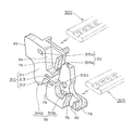
ここで、図3は、本発明の第1実施例であるケーブル類保護案内装置200の屈曲状態を示す斜視図であり、図4乃至図7は、ケーブル類保護案内装置200に用いた側板の斜視図であって、図4は、図3の矢印Aで示す側板の斜視図であり、図5は、図4のB方向から見た側板の斜視図であり、図6は、図4のC方向から見た側板の斜視図であり、図7は、図4のD方向から見た側板の斜視図である。
A cable
Here, FIG. 3 is a perspective view showing the bent state of the cable
本発明の第1実施例であるケーブル類保護案内装置200は、前述した本発明の理解を助けるための参考例のケーブル類保護案内装置100と同様に、例えば、半導体製造装置、創薬試験装置、車両用ドア開閉装置などの可動部と静止部とを接続し、電気信号の伝達や供給を行う電気ケーブルや圧力液体や圧力気体を供給するホースのようなケーブル類Cを保護案内するために使用されるもので、可動部と静止部(図示しない)とを接続するために長尺状に多数連結され、可動部と静止部との間の相対的な遠隔移動状況に応じて直線姿勢、あるいは、屈曲姿勢を呈することができ、図3に示すように、離間配置された左右一対の側板210A,210Bが長手方向に多数連結されているとともに、これらの側板210A,210Bの屈曲内周側及び屈曲外周側にそれぞれ結合アーム220が多数連結される側板210A,210Bの1つ置きの配置間隔で横架されてなり、これらの左右一対の側板210A,210Bと屈曲内周側及び屈曲外周側に横架状態で配置された結合アーム220,220とで囲繞される矩形状断面を呈したケーブル収納空間内にケーブル類Cが長手方向に沿って収納されるように構成されている。
なお、図3では、前述した可動部および静止部を図示していない。
The cable
In addition, in FIG. 3, the movable part and stationary part mentioned above are not illustrated.
本発明の第1実施例で用いた側板210Aは、図4に示すように、ポリアミド樹脂を用いて成型加工され、離間配置する左右一対で左右対称となるものであって、すなわち、これらの側板210は、図3に示すように、先行する側板210’に連結される前方側板部211と後続する側板210に連結される後方側板部212と前記前方側板部211と後方側板部212との間に介在して屈曲自在な継ぎ手部213とで一体に構成されている。
As shown in FIG. 4, the
そして、前記先行する側板210’の後方側板部212’とこの後方側板部212’に
後続して連結される側板210の前方側板部211との間には、相互に係合する屈曲外周側のスナップフィット機構Saと屈曲内周側のスナップフィット機構Sbとがそれぞれ設けられ、これらのスナップフィット機構Sa,Sbを介して隣接する側板210,210が相互に着脱自在となっており、側板210,210の切り継ぎ時における保守メンテナンスを簡便に達成できるようになっている。
すなわち、本第1実施例で屈曲外周側に採用したスナップフィット機構Saは、鉤状の係合フックからなる係合突起214aとこの係合フックからなる係合突起214aに着脱自在に係合する窓状の被係合孔215aとで構成され、他方、屈曲内周側に採用したスナップフィット機構Sbは、係合突起爪からなる係合突起214bとこの係合突起爪からなる係合突起214bを差し込み自在に係合するディンプル状の被係合孔215bとで構成されている。
Between the rear
That is, the snap-fit mechanism Sa employed on the bent outer peripheral side in the first embodiment is detachably engaged with the
さらに、前記側板210の継ぎ手部213より屈曲外周側に位置する前方側板部211の段違いにオフセットされた後端と後続する側板210’の前方側板部211’の前端との間、及び、側板210の継ぎ手部213より屈曲内周側に位置する側板210の後方側板部212の段違いにオフセットされた後端と後続する側板210’の後方側板部212’の前端との間には、側板210の直線連結状態を保持する2組の直線姿勢保持面、すなわち、屈曲外周側の直線姿勢保持面Xa、及び、屈曲内周側の直線姿勢保持面Xbがそれぞれ形成されている。
すなわち、前記側板210の直線連結状態を相互に当接して保持する屈曲外周側の直線姿勢保持面Xaが、前記側板210の継ぎ手部213より屈曲外周側に位置する前方側板部211の段違いにオフセットされた後端と後続する側板210’の前方側板部211’の前端との間にそれぞれ形成され、前記側板210の直線連結状態を相互に当接して保持する屈曲内周側の直線姿勢保持面Xbが、前記側板210の継ぎ手部213より屈曲内周側に位置する側板210の後方側板部212の段違いにオフセットされた後端と後続する側板210’の後方側板部212’の前端との間にそれぞれ形成されている。
また、前記側板210の継ぎ手部213より屈曲内周側に位置する後方側板部212の段違いにオフセットされた後端と後続する側板210’の後方側板部212‘の前端との間、及び、側板210の継ぎ手部213より屈曲外周側に位置する前方側板部211の段違いにオフセットされた後端と後続する側板210’の後方側板部212’の段違いにオフセットされた前端との間には、側板の屈曲連結状態を規制する2組の屈曲姿勢規制面、すなわち、屈曲内周側の屈曲姿勢規制面Yb、及び、屈曲外周側の屈曲姿勢規制面Yaがそれぞれ形成されている。
すなわち、前記側板210の屈曲連結状態を相互に当接して規制する屈曲内周側の屈曲姿勢規制面Ybが、前記側板210の継ぎ手部213より屈曲内周側に位置する後方側板部212の段違いにオフセットされた後端と後続する側板210’の後方側板部212’の前端との間にそれぞれ形成され、前記側板210の屈曲連結状態を相互に当接して規制する屈曲外周側の屈曲姿勢規制面Yaが、前記側板210の継ぎ手部213より屈曲外周側に位置する前方側板部211の段違いにオフセットされた後端と後続する側板210’の後方側板部212’の段違いにオフセットされた前端との間にそれぞれ形成されている。
Further, between the rear end offset by the step difference of the front
In other words, the linear outer peripheral posture holding surface Xa that holds the linearly connected state of the
Further, between the rear end of the rear
That is, the bending posture regulating surface Yb on the bent inner circumferential side that regulates the bent connection state of the
このようにして本発明の第1実施例であるケーブル類保護案内装置200は、図3に示すような直線姿勢保持時に、屈曲内周側の屈曲姿勢規制面Yb同士、及び、屈曲外周側の屈曲姿勢規制面Ya同士がそれぞれ相互に拡開した状態で屈曲外周側の直線姿勢保持面Xa同士、及び、屈曲内周側の直線姿勢保持面Xb同士がそれぞれ相互に当接して継ぎ手部213に負荷をかけることなく直線姿勢を確実に保持するとともに、図3に示されているような屈曲姿勢規制時に、屈曲外周側の直線姿勢保持面Xa同士、及び、屈曲内周側の直線姿勢保持面Xb同士がそれぞれ相互に拡開した状態で屈曲内周側の屈曲姿勢規制面Yb同士、及び、屈曲外周側の屈曲姿勢規制面Ya同士がそれぞれ相互に当接して継ぎ手部213に負荷をかけることなく屈曲姿勢を確実に保持するようになっている。
なお、本第1実施例における屈曲内周側の屈曲姿勢規制面Yb同士、及び、屈曲外周側の屈曲姿勢規制面Ya同士の形成する最大拡開角度α(図示しない)は、屈曲姿勢を連続して構成する側板210の数と屈曲半径に応じて所望の角度に定めることができる。
As described above, the cable
In the first embodiment, the maximum spread angle α (not shown) formed between the bending posture regulating surfaces Yb on the bending inner circumferential side and the bending posture regulating surfaces Ya on the bending outer circumferential side is continuous with the bending posture. The desired angle can be determined according to the number of
したがって、本発明の第1実施例であるケーブル類保護案内装置200は、部品点数を増加させることなく、部品製作負担や組立作業負担を軽減することができるとともに、屈曲動作の繰り返しによって生じがちな継ぎ手部213における不用意な外れを回避することができ、隣接する側板210が屈曲外周側と屈曲内周側に設けた2組のスナップフィット機構Sa,Sbを介して相互に着脱自在となるため、側板210の切り継ぎ時における保守メンテナンスを簡便に達成することができ、しかも、屈曲姿勢規制時に屈曲部位となる継ぎ手部213に発生しがちな負荷を回避して優れた耐久性を発揮することができるとともに、屈曲姿勢規制時及び直線姿勢保持時に生じる側板相互の面接触負荷が屈曲外周側と屈曲内周側とに二分されて分散するため、直線連結状態と屈曲連結状態とを耐久的かつ確実に保持することができる。
Therefore, the cable protection and
以下、本発明の第2実施例であるケーブル類保護案内装置300を図8乃至図12を用いて説明する。
ここで、図8は、ケーブル類保護案内装置300の屈曲状態を示す斜視図であり、図9乃至図12は、ケーブル類保護案内装置300に用いた側板の斜視図であって、図9は、図8の矢印Eで示す側板の斜視図であり、図10は、図9のF方向から見た側板の斜視図であり、図11は、図9のG方向から見た側板の斜視図であり、図12は、図9のH方向から見た側板の斜視図である。
Hereinafter, the cable
8 is a perspective view showing a bent state of the cable
本発明の第2実施例であるケーブル類保護案内装置300は、前述した第1実施例のケーブル類保護案内装置200と同様に、例えば、半導体製造装置、創薬試験装置、車両用ドア開閉装置などの可動部と静止部とを接続し、電気信号の伝達や供給を行う電気ケーブルや圧力液体や圧力気体を供給するホースのようなケーブル類Cを保護案内するために使用されるもので、可動部と静止部(図示しない)とを接続するために長尺状に多数連結され、可動部と静止部との間の相対的な遠隔移動状況に応じて直線姿勢、あるいは、屈曲姿勢を呈することができ、図8に示すように、離間配置された左右一対の側板310A,310Bが長手方向に多数連結されているとともに、これらの側板320A,310Bの屈曲内周側及び屈曲外周側にそれぞれ結合アーム320が多数連結される側板310A,310Bの1つ置きの配置間隔で横架されてなり、これらの左右一対の側板310A,310Bと屈曲内周側及び屈曲外周側に横架状態で配置された結合アーム320,320とで囲繞される矩形状断面を呈したケーブル収納空間内にケーブル類Cが長手方向に沿って収納されるように構成されている。
なお、図8では、前述した可動部および静止部を図示していない。
The cable
In addition, in FIG. 8, the movable part and stationary part mentioned above are not illustrated.
本第2実施例で用いた側板310A,310Bは、ポリアミド樹脂を用いて成型加工され、離間配置する左右一対で左右対称となるものであって、すなわち、これらの側板310は、図8に示すように、先行する側板310’に連結される前方側板部311と後続する側板310に連結される後方側板部312と前記前方側板部311と後方側板部312との間に介在して屈曲自在な継ぎ手部313とで一体に構成されている。
The
そして、前記先行する側板310’の後方側板部312’とこの後方側板部312’に後続して連結される側板310の前方側板部311との間には、相互に係合する屈曲外周側のスナップフィット機構Saと屈曲内周側のスナップフィット機構Sbと継ぎ手部313の近傍に採用したスナップフィット機構Scとがそれぞれ設けられ、これらのスナップフィット機構Sa,Sb,Scを介して隣接する側板310,310が相互に着脱自在となっており、側板310,310の切り継ぎ時における保守メンテナンスを簡便に達成できるようになっている。
すなわち、本第3実施例で屈曲外周側に採用したスナップフィット機構Saは、鉤状の係合フックからなる係合突起314aとこの係合フックからなる係合突起314aに着脱自在に係合する窓状の被係合孔315aとで構成され、他方、屈曲内周側に採用したスナップフィット機構Sbは、鉤状の係合フックからなる係合突起314bとこの係合フックからなる係合突起314bを着脱自在に係合する窓状の被係合孔315bとで構成されている。しかも、側板310の継ぎ手部313の近傍に採用したスナップフィット機構Scは、円柱状の係合ピンからなる係合突起314cとこの係合ピンからなる係合突起314cを着脱自在に係合する窓状の被係合孔315cとで構成されている。
Between the rear
That is, the snap-fit mechanism Sa adopted on the bent outer peripheral side in the third embodiment is detachably engaged with the
さらに、前記側板310の継ぎ手部313より屈曲外周側に位置する前方側板部311の段違いにオフセットされた後端と後続する側板310’の前方側板部311’の前端との間、及び、側板310の継ぎ手部313より屈曲内周側に位置する側板310の後方側板部312の段違いにオフセットされた後端と後続する側板310’の後方側板部312’の前端との間には、側板310の直線連結状態を保持する2組の直線姿勢保持面、すなわち、屈曲外周側の直線姿勢保持面Xa、及び、屈曲内周側の直線姿勢保持面Xbがそれぞれ形成されている。
すなわち、前記側板310の直線連結状態を相互に当接して保持する屈曲外周側の直線姿勢保持面Xaが、前記側板310の継ぎ手部313より屈曲外周側に位置する前方側板部311の段違いにオフセットされた後端と後続する側板310’の前方側板部311’の前端との間にそれぞれ形成され、前記側板310の直線連結状態を相互に当接して保持する屈曲内周側の直線姿勢保持面Xbが、前記側板310の継ぎ手部313より屈曲内周側に位置する側板310の後方側板部312の段違いにオフセットされた後端と後続する側板310’の後方側板部312’の前端との間にそれぞれ形成されている。
また、前記側板310の継ぎ手部313より屈曲内周側に位置する後方側板部312の段違いにオフセットされた後端と後続する側板310’の後方側板部312‘の前端との間、及び、側板310の継ぎ手部313より屈曲外周側に位置する前方側板部311の段違いにオフセットされた後端と後続する側板310’の後方側板部312’の段違いにオフセットされた前端との間には、側板の屈曲連結状態を規制する2組の屈曲姿勢規制面、すなわち、屈曲内周側の屈曲姿勢規制面Yb、及び、屈曲外周側の屈曲姿勢規制面Yaがそれぞれ形成されている。
すなわち、前記側板310の屈曲連結状態を相互に当接して規制する屈曲内周側の屈曲姿勢規制面Ybが、前記側板310の継ぎ手部313より屈曲内周側に位置する後方側板部312の段違いにオフセットされた後端と後続する側板310’の後方側板部312’の前端との間にそれぞれ形成され、前記側板310の屈曲連結状態を相互に当接して規制する屈曲外周側の屈曲姿勢規制面Yaが、前記側板310の継ぎ手部313より屈曲外周側に位置する前方側板部311の段違いにオフセットされた後端と後続する側板310’の後方側板部312’の段違いにオフセットされた前端との間にそれぞれ形成されている。
Furthermore, between the rear end offset by the step difference of the front
In other words, the linear outer peripheral posture holding surface Xa that holds the linearly connected state of the
Further, between the rear end of the rear
That is, the bending posture regulating surface Yb on the bent inner circumferential side that regulates the bent connection state of the
このようにして得られた本第2施例のケーブル類保護案内装置300は、図8に示すような直線姿勢保持時に、屈曲内周側の屈曲姿勢規制面Yb同士、及び、屈曲外周側の屈曲姿勢規制面Ya同士がそれぞれ相互に拡開した状態で屈曲外周側の直線姿勢保持面Xa同士、及び、屈曲内周側の直線姿勢保持面Xb同士がそれぞれ相互に当接して継ぎ手部313に負荷をかけることなく直線姿勢を確実に保持するとともに、図8に示されているような屈曲姿勢規制時に、屈曲外周側の直線姿勢保持面Xa同士、及び、屈曲内周側の直線姿勢保持面Xb同士がそれぞれ相互に拡開した状態で屈曲内周側の屈曲姿勢規制面Yb同士、及び、屈曲外周側の屈曲姿勢規制面Ya同士がそれぞれ相互に当接して継ぎ手部313に負荷をかけることなく屈曲姿勢を確実に保持するようになっている。
なお、本第2実施例における屈曲内周側の屈曲姿勢規制面Yb同士、及び、屈曲外周側の屈曲姿勢規制面Ya同士の形成する最大拡開角度α(図示しない)は、屈曲姿勢を連続して構成する側板310の数と屈曲半径に応じて所望の角度に定めることができる。
The cables
In the second embodiment, the maximum spread angle α (not shown) formed between the bending posture regulating surfaces Yb on the bending inner circumferential side and between the bending posture regulating surfaces Ya on the bending outer circumferential side is continuous with the bending posture. The desired angle can be determined according to the number of
したがって、本発明の第2実施例であるケーブル類保護案内装置300は、部品点数を増加させることなく、部品製作負担や組立作業負担を軽減することができるとともに、屈曲動作の繰り返しによって生じがちな継ぎ手部313における不用意な外れを回避することができ、隣接する側板310が屈曲外周側と屈曲内周側に設けた2組のスナップフィット機構Sa,Sbを介して相互に着脱自在となるため、側板310の切り継ぎ時における保守メンテナンスを簡便に達成することができ、しかも、屈曲姿勢規制時に屈曲部位となる継ぎ手部313に発生しがちな負荷を回避して優れた耐久性を発揮することができるとともに、屈曲姿勢規制時及び直線姿勢保持時に生じる側板相互の面接触負荷が屈曲外周側と屈曲内周側とに二分されて分散するため、直線連結状態と屈曲連結状態とを耐久的かつ確実に保持することができる。
Therefore, the cable
100 ,200 ,300 ・・・ケーブル類保護案内装置
110 ,210 ,310 ・・・側板
111 ,211 ,311 ・・・前方側板部
112 ,212 ,312 ・・・後方側板部
113 ,213 ,313 ・・・継ぎ手部
114a,214a,314a・・・屈曲外周側の係合突起
114b,214b,314b・・・屈曲内周側の係合突起
115a,215a,315a・・・屈曲外周側の被係合孔
115b,215b,315b・・・屈曲内周側の被係合孔
314c・・・係合突起
315c・・・被係合孔
120,220,320・・・結合アーム
Sa ,Sb ,Sc ・・・スナップフィット機構
Xa・・・屈曲外周側の直線姿勢保持面
Ya・・・屈曲外周側の屈曲姿勢規制面
Xb・・・屈曲内周側の直線姿勢保持面
Yb・・・屈曲内周側の屈曲姿勢規制面
C ・・・ケーブル類
α ・・・屈曲姿勢規制面の最大拡開角度
100, 200, 300 ・ ・ ・ Cables
Claims (1)
前記側板が、先行する側板に連結される前方側板部と後続する側板に連結される後方側板部と前記前方側板部と後方側板部との間に介在して屈曲自在な継ぎ手部とで一体に構成され、
前記側板に相互に係合させて連結するスナップフィット機構が、先行する側板の後方側板部と該後方側板部に後続して連結される側板の前方側板部との間に設けられ、
前記側板の直線連結状態を保持する直線姿勢保持面が、隣り合う側板の前方側板部の継ぎ手部より屈曲外周側の部位及び隣り合う側板の後方側板部の継ぎ手部より屈曲内周側の部位にそれぞれ形成されているとともに、
前記側板の屈曲連結状態を規制する屈曲姿勢規制面が、隣り合う側板の前方側板部の継ぎ手部より屈曲外周側の部位及び隣り合う側板の後方側板部の継ぎ手部より屈曲内周側の部位にそれぞれ形成されていることを特徴とするケーブル類保護案内装置。 A cable that connects a large number of a pair of left and right side plates that are spaced apart in the longitudinal direction and that has a coupling arm horizontally mounted at a predetermined interval on the bent inner peripheral side and the bent outer peripheral side of the side plate, and is surrounded by the side plate and the connecting arm. In the cable protection guide device that stores the cables in the storage space along the longitudinal direction and exhibits a linear posture and a bending posture,
The side plate is integrally formed with a front side plate portion connected to a preceding side plate, a rear side plate portion connected to a subsequent side plate, and a bendable joint portion interposed between the front side plate portion and the rear side plate portion. Configured,
A snap-fit mechanism that engages and connects with the side plates is provided between the rear side plate portion of the preceding side plate and the front side plate portion of the side plate that is connected subsequent to the rear side plate portion,
The linear posture holding surface that holds the linearly connected state of the side plates is located on the bent outer peripheral side portion from the joint portion of the front side plate portion of the adjacent side plate and the bent inner peripheral side portion from the joint portion of the rear side plate portion of the adjacent side plate. Each is formed,
The bending posture regulating surface that regulates the bent connection state of the side plates is located on the bent outer peripheral side portion from the joint portion of the front side plate portion of the adjacent side plate and on the bent inner peripheral side portion from the joint portion of the rear side plate portion of the adjacent side plate. A cable protection and guide device characterized by being formed respectively.
Priority Applications (6)
| Application Number | Priority Date | Filing Date | Title |
|---|---|---|---|
| JP2005068498A JP4111958B2 (en) | 2005-03-11 | 2005-03-11 | Cable protection guide device |
| US11/271,551 US7204075B2 (en) | 2005-03-11 | 2005-11-09 | Cable or the like protection and guide device |
| TW094139407A TW200632232A (en) | 2005-03-11 | 2005-11-10 | Cable or the like protection and guide device |
| KR1020050133099A KR100979829B1 (en) | 2005-03-11 | 2005-12-29 | Cable or the like protection and guide device |
| DE102006011229A DE102006011229A1 (en) | 2005-03-11 | 2006-03-10 | Device for protecting and guiding cables and the like |
| CNB2006100595347A CN100538108C (en) | 2005-03-11 | 2006-03-10 | Cable like protection and guide device |
Applications Claiming Priority (1)
| Application Number | Priority Date | Filing Date | Title |
|---|---|---|---|
| JP2005068498A JP4111958B2 (en) | 2005-03-11 | 2005-03-11 | Cable protection guide device |
Publications (2)
| Publication Number | Publication Date |
|---|---|
| JP2006250258A JP2006250258A (en) | 2006-09-21 |
| JP4111958B2 true JP4111958B2 (en) | 2008-07-02 |
Family
ID=36914953
Family Applications (1)
| Application Number | Title | Priority Date | Filing Date |
|---|---|---|---|
| JP2005068498A Active JP4111958B2 (en) | 2005-03-11 | 2005-03-11 | Cable protection guide device |
Country Status (6)
| Country | Link |
|---|---|
| US (1) | US7204075B2 (en) |
| JP (1) | JP4111958B2 (en) |
| KR (1) | KR100979829B1 (en) |
| CN (1) | CN100538108C (en) |
| DE (1) | DE102006011229A1 (en) |
| TW (1) | TW200632232A (en) |
Cited By (1)
| Publication number | Priority date | Publication date | Assignee | Title |
|---|---|---|---|---|
| KR101512839B1 (en) | 2012-02-17 | 2015-04-16 | 가부시기가이샤쯔바기모도체인 | Cable protectition and guide device |
Families Citing this family (28)
| Publication number | Priority date | Publication date | Assignee | Title |
|---|---|---|---|---|
| JP4104607B2 (en) * | 2005-03-30 | 2008-06-18 | 株式会社椿本チエイン | Cable clamp member of cable protection guide device |
| JP4111967B2 (en) * | 2005-09-29 | 2008-07-02 | 株式会社椿本チエイン | Cable protection guide device |
| KR100587499B1 (en) * | 2005-10-18 | 2006-06-08 | 씨피시스템(주) | A clean room chain |
| JP4111976B2 (en) * | 2006-01-19 | 2008-07-02 | 株式会社椿本チエイン | Cable protection guide device |
| JP4789632B2 (en) * | 2006-01-20 | 2011-10-12 | 株式会社椿本チエイン | Cable protection guide device |
| DE102006013682A1 (en) * | 2006-03-24 | 2007-10-11 | Kabelschlepp Gmbh | Warp-free chain link |
| JP4118308B2 (en) * | 2006-04-14 | 2008-07-16 | 株式会社椿本チエイン | Cable protection guide device |
| JP4111987B1 (en) | 2007-02-07 | 2008-07-02 | 株式会社椿本チエイン | Cable protection guide device |
| DE102007017940A1 (en) * | 2007-04-13 | 2008-10-16 | Igus Gmbh | Side wall segment for a cable guide device, line guide device with side wall segment and method for producing the side wall segment |
| JP4118314B1 (en) * | 2007-04-27 | 2008-07-16 | 株式会社椿本チエイン | Cable protection guide device |
| JP2008281165A (en) | 2007-05-14 | 2008-11-20 | Tsubakimoto Chain Co | Cable protecting and guiding device |
| KR100924679B1 (en) | 2007-12-17 | 2009-11-03 | 주식회사 코닥트 | Cableveyor |
| JP4503658B2 (en) | 2008-04-25 | 2010-07-14 | 株式会社椿本チエイン | Cable protection guide device |
| US8991147B2 (en) * | 2008-08-05 | 2015-03-31 | International Business Machines Corporation | Augmented track to facilitate removal of stiffening layers from a cable retained in the track |
| KR100959783B1 (en) * | 2008-10-15 | 2010-05-28 | 한국원자력 통제기술원 | Cable guide apparatus of radiation probe system for spent fuel verification |
| JP5047214B2 (en) * | 2009-04-09 | 2012-10-10 | 株式会社椿本チエイン | Cable protection guide device |
| ES2456354T3 (en) * | 2009-08-05 | 2014-04-22 | Prysmian S.P.A. | Flat power cable |
| DE202016104470U1 (en) * | 2016-08-12 | 2017-11-14 | Igus Gmbh | Connecting device and cable guide device |
| DE202016104838U1 (en) | 2016-09-01 | 2017-12-04 | Igus Gmbh | Cable guide |
| CN106882723A (en) * | 2017-03-07 | 2017-06-23 | 南京智真电子科技股份有限公司 | A kind of interior cabling rigidity sprocket wheel transmission lifting rod |
| JP6873828B2 (en) * | 2017-05-31 | 2021-05-19 | 株式会社ミツバ | Vehicle switchgear |
| EP3591776B1 (en) * | 2018-07-05 | 2022-01-05 | TRUMPF Medizin Systeme GmbH + Co. KG | Cable routing system |
| DE202019103068U1 (en) * | 2019-05-29 | 2020-06-30 | Igus Gmbh | Cable routing device for clean room applications |
| CN111168729A (en) * | 2020-01-09 | 2020-05-19 | 杨西望 | Reciprocating data positioning motion control system |
| DE202021101933U1 (en) | 2021-04-09 | 2022-07-21 | Igus Gmbh | Energy guiding chain with flexible joint connectors, as well as side straps and joint connectors for this |
| TW202202757A (en) | 2020-05-27 | 2022-01-16 | 德商易格斯股份有限公司 | Energy guide chain with flexible joint connectors as well as side plates and joint connectors for same |
| US11848546B2 (en) * | 2021-02-01 | 2023-12-19 | Magna Powertrain Of America, Inc. | High voltage wire protection system for electric vehicles |
| EP4348323A1 (en) * | 2021-05-26 | 2024-04-10 | PPC Broadband, Inc. | Flexible cable support |
Family Cites Families (11)
| Publication number | Priority date | Publication date | Assignee | Title |
|---|---|---|---|---|
| IT208046Z2 (en) * | 1986-09-15 | 1988-03-31 | Tecno Mobili E Forniture Per A | FLEXIBLE CABLE ORGAN WITH BIDIRECTIONAL JOINTS. |
| EP1076784B1 (en) * | 1998-05-05 | 2003-10-22 | IGUS SPRITZGUSSTEILE FÜR DIE INDUSTRIE GmbH | Energy guiding chain |
| DE19839966A1 (en) * | 1998-09-02 | 2000-04-06 | Kabelschlepp Gmbh | Line routing arrangement for routing at least one line |
| WO2000063583A1 (en) * | 1999-04-19 | 2000-10-26 | Igus Spritzgussteile für die Industrie GmbH | Conduit carrier chain |
| DE19962829A1 (en) * | 1999-12-23 | 2001-08-23 | Kabelschlepp Gmbh | Strand and method for producing a fiber-reinforced strand of a cable routing arrangement |
| DE20107003U1 (en) * | 2001-04-23 | 2002-09-19 | Igus Gmbh | Power supply chain |
| JP3349146B1 (en) * | 2001-09-06 | 2002-11-20 | 株式会社椿本チエイン | Cable protection guide |
| JP3722477B2 (en) | 2002-04-02 | 2005-11-30 | 株式会社椿本チエイン | Cable protection guide |
| JP3716989B2 (en) * | 2003-05-07 | 2005-11-16 | 株式会社椿本チエイン | Cable protection guide device |
| JP4144869B2 (en) * | 2003-09-11 | 2008-09-03 | 株式会社椿本チエイン | Cable protection guide device |
| JP4789632B2 (en) * | 2006-01-20 | 2011-10-12 | 株式会社椿本チエイン | Cable protection guide device |
-
2005
- 2005-03-11 JP JP2005068498A patent/JP4111958B2/en active Active
- 2005-11-09 US US11/271,551 patent/US7204075B2/en active Active
- 2005-11-10 TW TW094139407A patent/TW200632232A/en unknown
- 2005-12-29 KR KR1020050133099A patent/KR100979829B1/en active IP Right Grant
-
2006
- 2006-03-10 DE DE102006011229A patent/DE102006011229A1/en active Pending
- 2006-03-10 CN CNB2006100595347A patent/CN100538108C/en active Active
Cited By (1)
| Publication number | Priority date | Publication date | Assignee | Title |
|---|---|---|---|---|
| KR101512839B1 (en) | 2012-02-17 | 2015-04-16 | 가부시기가이샤쯔바기모도체인 | Cable protectition and guide device |
Also Published As
| Publication number | Publication date |
|---|---|
| TWI357958B (en) | 2012-02-11 |
| CN1831369A (en) | 2006-09-13 |
| US20060201840A1 (en) | 2006-09-14 |
| TW200632232A (en) | 2006-09-16 |
| US7204075B2 (en) | 2007-04-17 |
| JP2006250258A (en) | 2006-09-21 |
| KR100979829B1 (en) | 2010-09-02 |
| DE102006011229A1 (en) | 2006-09-14 |
| KR20060097554A (en) | 2006-09-14 |
| CN100538108C (en) | 2009-09-09 |
Similar Documents
| Publication | Publication Date | Title |
|---|---|---|
| JP4111958B2 (en) | Cable protection guide device | |
| JP4789632B2 (en) | Cable protection guide device | |
| JP4111976B2 (en) | Cable protection guide device | |
| JP4111967B2 (en) | Cable protection guide device | |
| JP4118304B2 (en) | Cable protection guide device | |
| JP4540722B2 (en) | Cable protection guide device | |
| JP4118306B2 (en) | Cable protection guide device | |
| JP5127943B2 (en) | Articulated cable protection guide device | |
| JP4302752B2 (en) | Cable protection guide device | |
| JP4751862B2 (en) | Cable protection guide device | |
| JP4111987B1 (en) | Cable protection guide device | |
| JP5541746B2 (en) | Cable protection guide device | |
| JP4114815B1 (en) | Cable protection guide device | |
| JP4118311B2 (en) | Cable protection guide device | |
| JP2009264501A (en) | Cable protecting guide device | |
| KR101480972B1 (en) | Bracket for cable chain | |
| JP2008281165A (en) | Cable protecting and guiding device | |
| TWI792115B (en) | Apparatus for guiding elongated object | |
| JP4108736B1 (en) | Cable protection guide device | |
| JP2016195479A (en) | Fixing structure of wiring harness |
Legal Events
| Date | Code | Title | Description |
|---|---|---|---|
| A621 | Written request for application examination |
Free format text: JAPANESE INTERMEDIATE CODE: A621 Effective date: 20070326 |
|
| A871 | Explanation of circumstances concerning accelerated examination |
Free format text: JAPANESE INTERMEDIATE CODE: A871 Effective date: 20071127 |
|
| A975 | Report on accelerated examination |
Free format text: JAPANESE INTERMEDIATE CODE: A971005 Effective date: 20080220 |
|
| A131 | Notification of reasons for refusal |
Free format text: JAPANESE INTERMEDIATE CODE: A131 Effective date: 20080229 |
|
| A521 | Written amendment |
Free format text: JAPANESE INTERMEDIATE CODE: A523 Effective date: 20080314 |
|
| TRDD | Decision of grant or rejection written | ||
| A01 | Written decision to grant a patent or to grant a registration (utility model) |
Free format text: JAPANESE INTERMEDIATE CODE: A01 Effective date: 20080407 |
|
| A61 | First payment of annual fees (during grant procedure) |
Free format text: JAPANESE INTERMEDIATE CODE: A61 Effective date: 20080408 |
|
| R150 | Certificate of patent or registration of utility model |
Ref document number: 4111958 Country of ref document: JP Free format text: JAPANESE INTERMEDIATE CODE: R150 Free format text: JAPANESE INTERMEDIATE CODE: R150 |
|
| FPAY | Renewal fee payment (event date is renewal date of database) |
Free format text: PAYMENT UNTIL: 20110418 Year of fee payment: 3 |
|
| FPAY | Renewal fee payment (event date is renewal date of database) |
Free format text: PAYMENT UNTIL: 20120418 Year of fee payment: 4 |
|
| FPAY | Renewal fee payment (event date is renewal date of database) |
Free format text: PAYMENT UNTIL: 20120418 Year of fee payment: 4 |
|
| FPAY | Renewal fee payment (event date is renewal date of database) |
Free format text: PAYMENT UNTIL: 20130418 Year of fee payment: 5 |
|
| FPAY | Renewal fee payment (event date is renewal date of database) |
Free format text: PAYMENT UNTIL: 20140418 Year of fee payment: 6 |