JP4101712B2 - Electronic drawing storage method, electronic drawing storage system, and drawing data providing system - Google Patents
Electronic drawing storage method, electronic drawing storage system, and drawing data providing system Download PDFInfo
- Publication number
- JP4101712B2 JP4101712B2 JP2003206408A JP2003206408A JP4101712B2 JP 4101712 B2 JP4101712 B2 JP 4101712B2 JP 2003206408 A JP2003206408 A JP 2003206408A JP 2003206408 A JP2003206408 A JP 2003206408A JP 4101712 B2 JP4101712 B2 JP 4101712B2
- Authority
- JP
- Japan
- Prior art keywords
- data
- image data
- drawing data
- standard
- difference
- Prior art date
- Legal status (The legal status is an assumption and is not a legal conclusion. Google has not performed a legal analysis and makes no representation as to the accuracy of the status listed.)
- Expired - Fee Related
Links
Images


Landscapes
- Processing Or Creating Images (AREA)
Description
【0001】
【発明の属する技術分野】
本発明は、文字、記号、線分が混在する図面を電子化して保管する方法とシステムおよび電子化した図面データの提供システムに関する。
【0002】
【従来の技術】
計算機支援による文書類の管理が普及するのに伴い、過去に作成されて紙図面の形態で保管されている図面や他社から紙図面の形態で提供された図面などをスキャナで読込み込んで電子化し、電子化図面として保管できるようにしたり、あるいはその電子化図面のデータを提供するサービスが行われたりしている。そのような例として、例えば特許文献1には、紙図面を光学的に読み取ってそのままイメージデータとして保管・提供する技術が開示されている。また特許文献2には、紙文書類を光学的に読み取って電子化する技術として、イメージを含む文書類を電子化の対象とする場合で、その文字領域とイメージ領域を分けて抽出し、文字領域に対しては文字認識で電子化を行い、イメージ領域に対しては圧縮処理を加えたイメージデータとして電子化する技術が開示されている。
【0003】
この他にも、図面に文字、記号、線分などで表されている情報をイメージとして光学的に読み込んだ後に、それを文字列で記述される(文字コードのみで記述される)電子データに変換し、例えばテキスト・ファイルやバイナリ・ファイルとして保管する方法も知られている。
【0004】
【特許文献1】
特開2001−350824号公報
【特許文献2】
特開2000−306103号公報
【0005】
【発明が解決しようとする課題】
特許文献1に開示の技術のように、図面の全体をイメージデータ形式で保管したり提供したりする方式は、図面に含まれる情報を漏れなく扱えるという点で優れている。しかし、図面の全体をイメージデータ形式で扱う場合には、例えばビットマップデータ(BMPデータ)として作成されるイメージデータのデータ量が膨大なものになるため、保管に必要な記憶容量が非常に大きくなるし、また通信網を介してオンラインで提供する場合にデータの転送に多大な時間を要する。そこで、図面の電子化に際して、データ量をできるだけ少なくし、なおかつ図面に含まれる情報を漏れなく電子化することが望まれる。このデータ量の削減に従来より用いられているのは圧縮である。その圧縮手法としては、国際的に標準化されているものとしてJPEGがあり、また例えばランレングス符号化法なども用いられている。しかし、これらの圧縮手法を用いても、情報の欠落を防止できる範囲の圧縮であれば、データ量の削減程度は必ずしも十分なものとは言えない。
【0006】
一方、特許文献2に開示の技術のように、文字領域とイメージ領域に分けて電子化する手法は、文字データがイメージデータに較べて格段に少ないデータ量で済むことから、データ量の削減に有効である。しかし特許文献2に開示の技術は、文字領域とイメージ領域とを分離しやすい通常の文書類に対しては有効であるものの、文字、記号、線分が混在している設計図面への適用は困難である。
【0007】
また上記した、図面に含まれる情報を認識・抽出して文字列で記述される電子データに変換して保管する手法は、図面をイメージデータとして保管する場合に較べて、大幅にデータ量を削減できる。しかし、既存の紙図面ではフリーハンドによる手書き部分が含まれている場合が少なくない。そして、そのような部分は電子化できない場合が多く、そのために情報の欠落を生じるという問題がある。また手書き部分でなくても、認識漏れや誤認識などによっても情報の欠落を生じる。
【0008】
本発明は、以上のような事情を背景になされたものであり、文字、記号、線分が混在し、さらに手書き部分も含まれるような図面であっても情報を欠落させることなく、しかも図面全体をイメージデータとして保管する場合に較べて大幅に少ないデータ量で電子化して保管することのできる図面の電子化保管方法とシステムおよびそれらを用いた電子化図面データの提供システムの提供を目的としている。
【0009】
【課題を解決するための手段】
上記目的の一つを達成するために、本発明では、図面を電子化して保管する方法において、保管対象の図面についてのイメージデータ形式の原図面イメージデータに含まれる文字、記号、線分などの標準的図面構成要素を抽出する工程、抽出された前記標準的図面構成要素に関して文字列で記述される形式の第1の図面データを作成する工程、前記第1の図面データを変換してイメージデータ形式の差分取得用イメージデータを作成する工程、前記差分取得用イメージデータと前記原図面イメージデータとの差分を取って差分イメージデータを作成する工程、前記差分イメージデータを基にイメージデータ形式の第2の図面データを作成する工程、前記第1の図面データと前記第2の図面データを保管図面データとして記憶手段に格納する工程を含んでいることを特徴としている。
【0010】
また本発明では、上記のような図面の電子化保管方法について、前記標準的図面構成要素の抽出の信頼度を評価する工程をさらに含み、前記信頼度が所定以上である標準的図面構成要素だけを前記第1の図面データ図に取り込むようにしている。
【0011】
また本発明では、上記のような図面の電子化保管方法について、前記標準的図面構成要素間の対応関係、説明関係、接続関係を認識する統合認識工程をさらに含ませるものとしている。
【0012】
また本発明では、上記のような図面の電子化保管方法について、前記差分イメージデータのノイズを除去する工程をさらに含ませるものとしている。
【0013】
また本発明では、上記のような図面の電子化保管方法について、前記差分イメージデータから残存図面情報だけを部分的に取り出して前記第2の図面データを作成するようにしている。
【0014】
また本発明では、上記のような図面の電子化保管方法について、前記第1の図面データと第2の図面データを圧縮する工程をさらに含ませるものとしている。
【0015】
また本発明では、上記のような図面の電子化保管方法について、複数の保管対象図面に共通する図面情報を別のファイルとして保管するようにしている。
【0016】
また本発明では、上記のような図面の電子化保管方法について、前記標準的図面構成要素に対して判定基準を設定し、その判定基準を満足させる標準的図面構成要素だけを原図面イメージデータから抽出するようにしている。
【0017】
また本発明では、上記目的の他の一つを達成するために、図面を電子化して保管するためのシステムにおいて、保管対象の図面についてのイメージデータ形式の原図面イメージデータに含まれる文字、記号、線分などの標準的図面構成要素を抽出する手段、抽出された前記標準的図面構成要素に関して文字列で記述される形式の第1の図面データを作成する手段、前記第1の図面データを変換してイメージデータ形式の差分取得用イメージデータを作成する手段、前記差分取得用イメージデータと前記原図面イメージデータとの差分を取って差分イメージデータを作成する手段、前記差分イメージデータを基にイメージデータ形式の第2の図面データを作成する手段、前記第1の図面データと前記第2の図面データを保管図面データとして記憶する手段を備えていることを特徴としている。
【0018】
また本発明では、上記のような図面の電子化保管システムについて、前記標準的図面構成要素の抽出の信頼度を評価する手段をさらに備え、前記信頼度が所定以上である標準的図面構成要素だけを前記第1の図面データに取り込むようにしている。
【0019】
また本発明では、上記のような図面の電子化保管システムについて、前記標準的図面構成要素間の対応関係、説明関係、接続関係を認識する統合認識手段をさらに備えるものとしている。
【0020】
また本発明では、上記のような図面の電子化保管システムについて、前記第1の図面データと第2の図面データを圧縮する手段をさらに備えるものとしている。
【0021】
また本発明では、上記目的のさらに他の一つを達成するために、電子化された図面データを提供するシステムにおいて、上記のような図面の電子化保管方法による電子化図面を保管する手段が図面提供者側に設けられるとともに、前記電子化図面を保管する手段に通信手段を介して接続された顧客端末が顧客側に設けられていることを特徴としている。
【0022】
また本発明では、上記のような図面データ提供システムについて、前記顧客端末に、前記第1の図面データ用の圧縮・復元手段、前記第2の図面データ用の圧縮・復元手段、前記第1の図面データと第2の図面データを表示する手段、前記第1の図面データを編集する手段、および前記編集の結果を図面提供者側の前記保管手段に送信する手段を設けるものとしている。
【0023】
【発明の実施の形態】
以下、本発明の実施の形態について図面を参照して説明する。図1は本発明の第1の実施形態による図面の電子化保管方法を実施するのに用いられるシステムの機能に基づく全体構成を示すブロック図であり、図2は機器的な全体構成を示す図である。
【0024】
本発明による図面の電子化保管方法ないしシステムでは、紙図面の形態の図面を電子化する場合と、既に電子化して保管されている図面を保管替えする場合とがある。すなわち本発明では、まず保管対象の図面についてイメージデータ形式の原図面イメージデータ1を取得し、それを処理して保管図面データを作成する。そしてその原図面イメージデータ1には、イメージ入力装置10により、紙図面を光学的に読み取って例えばビットマップデータなどのイメージデータ形式で取り込まれたデータである場合と、既に電子化されている図面をイメージデータに変換して入力したデータである場合とがある。既に電子化されているデータをイメージデータに変換するについては、多くの方法が公知であり、例えば公開文献(PostScript&Acrobat/PDF、トーマス・マーツ著、東京電機大学出版局)に記載されている方法を用いることができる。原図面イメージデータ1の色数は特に制限されるものではないが、白黒の図面を読み取った場合には、0または1で表される2値化したイメージデータに変換しておくことが、最終的に保管する電子化図面のファイルサイズを削減する上で有利である。以下では、2値化したイメージデータを前提として説明する。なお、イメージ入力装置10は、ノイズ除去、傾き補正などの処理を行う機能を有することが望ましい。
【0025】
本実施形態における図面の電子化保管システムは、第1の図面データ作成部2、第2の図面データ作成部3、第1の図面データ圧縮部4、および第2の図面データ圧縮部5を有している。これらは何れもプログラム内部で処理される機能であり、したがってそれぞれの機能を実行する手段でもあり、C++などのプログラム言語で記述され、通常は磁気ディスク装置11に保存されている。プログラムが起動されると、それはメモリ15に割り当てられ、プログラムに従った各種の演算がCPU(中央演算装置)16、メモリ15などを用いて実行される。なお、プログラムは専用のメモリにあらかじめ格納しておいても良いし、各プログラムをそれぞれ専用のCPUで実行するように構成しても良い。
【0026】
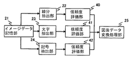
第1の図面データ作成部2はイメージデータ記憶部21、線分抽出部22、文字抽出部23、記号抽出部24、図面データ変換処理部25から形成されている。イメージデータ記憶部21は、入力された原図面イメージデータ1を記憶手段に格納する処理を行う。その記憶手段としては、例えばメモリ15が用いられる。線分抽出部22は、原図面イメージデータ1に含まれている線分を認識して抽出する。具体的には、原図面イメージデータ1に含まれる各線分について、その位置座標、太さ、種類(実線、破線等)などの情報を取得することで線分の認識・抽出をなす。文字抽出部23は、原図面イメージデータ1に含まれている文字を認識して抽出する。具体的には、原図面イメージデータ1に含まれている各文字について、その種類、位置座標、大きさなどの情報を取得することで文字の認識・抽出をなす。なお、図面で用いられる文字の種類はそれほど多くないのが通常である。そこで認識対象の文字の種類を一般的な図面で通常的に使用される範囲に限定するようにしてもよく、そのようにすることで、文字抽出部23における処理の負担を軽減できる。記号抽出部24は、原図面イメージデータ1に含まれている記号(例えば配管図面であれば、弁やポンプなどの図記号)を認識して抽出する。具体的には、原図面イメージデータ1に含まれている各記号についてその種類、位置座標、大きさなどの情報を取得することで記号の認識・抽出をなす。図面データ変換処理部25では、標準的図面構成要素の認識結果が種類、座標などのデータとして一定のルールにしたがって変換処理され、文字列で記述される形式の第1の図面データが作成される。作成された第1の図面データは、例えばテキストファイルとして磁気ディスク装置11に格納される。ここで、標準的図面構成要素とは、線分抽出部22、文字抽出部23、記号抽出部24それぞれでの認識・抽出の対象としてあらかじめ定めてある図面情報の構成要素のことであり、したがって線分、文字、記号が少なくとも含まれる。
【0027】
第2の図面データ作成部3は、イメージデータ変換部31、差分処理部32、ノイズ除去部33、図面データ取得部34から構成されている。イメージデータ変換部31は、第1の図面データ作成部2で作成された第1の図面データをイメージデータ形式に変換して差分取得用イメージデータを作成する。つまりイメージデータ変換部31は差分取得用イメージデータの作成手段として機能する。
【0028】
差分処理部32は、原図面イメージデータ1と上記の差分取得用イメージデータとの差分をとって差分イメージデータを作成する。つまり差分処理部32は差分イメージデータの作成手段として機能する。この処理は、本発明が図面の電子化保管を文字列で記述される形式の第1の図面データとイメージデータ形式の第2の図面データの2本立てで行うことに関係している。すなわち本発明では、文字列で記述される形式の第1の図面データとイメージデータ形式の第2の図面データとを組み合わせて図面の電子化保管をなすことで、保管対象の図面に含まれる手書き部分などのように線分、文字、記号として認識できない部分があったり、あるいは線分、文字、記号について認識漏れや誤認識があっても情報の欠落を生じることなく図面の電子化保管を行えるようにしている。このような2本立て方式においては、第1の図面データとすることができた部分について第2の図面データから省くのが最終的な保管図面データのデータ量を削減させるのに適切である。このような理由から原図面イメージデータ1と差分取得用イメージデータとの差分をとって差分イメージデータを作成する。
【0029】
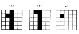
図3は差分処理における各データの例を示すものであり、(a)は原図面イメージデータ、(b)は差分取得用イメージデータ、(c)は差分イメージデータである。なお差分処理においては、原図面イメージデータの画素が0(黒)で差分取得用イメージデータの画素が1(白)である場合、差分イメージデータの画素を0とするようにしている。
【0030】
ノイズ除去部33は、差分イメージデータからノイズを除去する。差分イメージデータのノイズには、原図面イメージデータ1に最初から存在していたノイズと差分処理の過程で生じるノイズがある。ノイズであるか否かは、例えば一定の範囲より狭い範囲内で画素群が黒であっても、その画素群から一定の距離以内に、一定の範囲より広い範囲で黒となっている画素群がない場合にはその画素群をノイズとする、というようにして判定する。
【0031】
図面データ取得部34は、差分イメージデータに図面情報が残存している場合にその残存図面情報の部分だけをイメージデータ形式で取り出して第2の図面データを作成する。残存図面情報を取り出すには、残存図面情報部分をイメージデータ形式で切り出して部分的なイメージデータを取得するとともに、それが存在する領域の位置情報を取得する。そして各部分的イメージデータに所定のファイル名を付す。すなわち第2の図面データは、それぞれ所定のファイル名と存在領域の位置情報で特定される部分的イメージデータからなるデータとして作成される。なお第2の図面データについては、原図面イメージデータ1に関する解像度情報も含ませるのが好ましい。解像度情報とはDPI(Dot Per Inch)のように画素の密度を表す情報であり、このような解像度情報を保持することで、原図面イメージデータ1を読み込んだときと同じ大きさで第2の図面データを出力することが容易になる。
【0032】
第1の図面データ圧縮部4は第1の図面データを圧縮処理する。第1の図面データは、上述のように例えばテキストデータ形式で作成されている。テキストデータを圧縮する手法としてはハフマン符号化法などが知られており、これらの圧縮方式を用いたソフトウェアも数多く存在するので、それらを利用することができる。
【0033】
第2の図面データ圧縮部5は第2の図面データを圧縮処理する。第2の図面データは、上述のようにビットマップデータなどのイメージデータ形式で作成されている。イメージデータを圧縮する手法としてはランレングス符号化法やJPEG圧縮方式などが知られており、これらを利用することができる。
【0034】
データ記憶部6は第1の図面データ圧縮部4で圧縮処理された第1の図面データと第2の図面データ圧縮部5で圧縮処理された第2の図面データそれぞれを保管図面データとして保管するために記憶手段、具体的には磁気ディスク装置11に格納する機能を有する。またデータ記憶部6は、保管図面データの格納を終えた後で、原図面イメージデータ1、圧縮前の第1、第2の各図面データなどを、それらが他の用途で使用されない限り、メモリ15や磁気ディスク装置11から削除する機能も有する。
【0035】
ここで、図2に見られるように、図面の電子化保管システムは、その機器的な構成として、以上の説明で出てきたイメージ入力装置10、磁気ディスク装置11、CPU16の他に、操作者がシステムを起動する命令を入力したり、システムの動作を確認したりするのに用いられるキーボード12、マウス13、ディスプレイ14を含んでいる。これは図面の電子化保管システムを専用の装置として構成する場合の例である。このような構成に替えて、図面の読み取り機能を有する例えば複写機、ファクシミリ装置などに本発明を適用した機器構成とすることも可能である。
【0036】
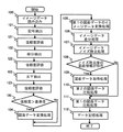
以下では図4のフローチャートと図5から図8の説明図を用いて、全体の実施手順を説明する。まず、ステップ100で原図面イメージデータ1がイメージ入力装置10で読み込まれる。読み込まれた原図面イメージデータ1の例を図5に示す。原図面イメージデータ1は、図面枠外領域200、注記領域201、関連図書定義領域202、図面定義領域203、線分210、記号220、文字230、手書き文字240などを図面情報として含んでおり、汚れ250が含まれている場合もある。
【0037】
次に、ステップ101で原図面イメージデータ1に含まれている記号を記号抽出部24により認識して抽出する。具体的には、原図面イメージデータ1に含まれている各記号(図5の例では弁記号やポンプ記号など)についてその種類、位置座標、大きさなどの情報を取得し、それをメモリ15あるいは磁気ディスク装置11に格納する。ステップ102では原図面イメージデータ1に含まれる線分を線分抽出部22により抽出する。具体的には、原図面イメージデータ1に含まれている各線分についてその位置座標、太さ、種類などの情報を取得し、それをメモリ15あるいは磁気ディスク装置11に格納する。ステップ103では原図面イメージデータ1に含まれる文字を文字抽出部23により抽出する。具体的には、原図面イメージデータ1に含まれている各文字(図5の例では「弁A」、「ポンプB」など)についてその種類、位置座標、大きさなどの情報を取得し、それをメモリ15あるいは磁気ディスク装置11に格納する。ここで、記号抽出、線分抽出、文字抽出の実行は必ずしもこの順番に限定する必要はない。また、それぞれの認識ごとに、既に認識した標準的図面構成要素を消去する処理手順とすることも可能であり、そのようにすることにより、重複認識を防止し、認識精度を向上させることができる。なお、図面枠外領域200、注記領域201、関連図書定義領域202、図面定義領域203は、枠線や各種の記述で構成されており、線分、文字、記号として認識・抽出される。
【0038】
ステップ104では、標準的図面構成要素の認識・抽出結果が種類、座標などのデータとして一定のルールにしたがって図面データ変換処理部25により変換処理され、文字列で記述される形式の第1の図面データが作成される。作成された第1の図面データは磁気ディスク装置11に格納される。第1の図面データのファイル形式としては、テキストファイルを用いることができ、またCAD(コンピュータ支援設計)ソフトで標準的に使用されるファイル形式なども用いることができる。
【0039】
ステップ105では、イメージデータ変換部31により、第1の図面データをイメージデータ形式に変換して差分取得用イメージデータを作成する。図6に差分取得用イメージデータの例を示す。差分取得用イメージデータに含まれる情報は第1の図面データに含まれるそれと同じである。図6から、第1の図面データないし差分取得用イメージデータには、図面枠外領域200、注記領域201、関連図書定義領域202、図面定義領域203、線分210、記号220、文字230などが含まれていることが分る。ここで、図面枠外領域200のように複数の図面に共通する図面情報に関しては、第1の図面データとは別の図面データファイルなどとして磁気ディスク装置11に保管しておき、保管図面を表示するときなどにそれを呼び出せるようにしておくのが好ましい。このようにすることで保管に必要なファイルサイズを縮小することが可能となる。
【0040】
ステップ106では、原図面イメージデータ1と差分取得用イメージデータとの差分をとって差分イメージデータを作成する。すなわち、図5の原図面イメージデータから図6の差分取得用イメージデータを差し引き、図7の差分イメージデータを得る。図7の差分イメージデータは、ノイズ除去前の差分イメージデータであり、第1の図面データとして認識・抽出されなかった、手書き文字240や汚れ250が含まれている。
【0041】
ステップ107では、ノイズ除去部33により、意味のない画像である汚れ250が除去され、図8のノイズ除去後の差分イメージデータが得られる。
【0042】
ステップ108では、第2の図面データとして取り込む必要のある図面情報がノイズ除去後の差分イメージデータに残存しているかどうかが確認され、残存図面情報がある場合にはステップ109とステップ110が実行される。そのような残存図面情報としては、図8の例における手書き文字240がある。手書き文字240も文字抽出部23で認識・抽出が可能であれば、標準的図面構成要素の文字として認識・抽出することになるが、一般的には手書き文字240を精度よく認識・抽出することは現状では困難である。そこでイメージデータ形式で取り込むようにする。原図面イメージデータ1に含まれる図面情報が全て第1の図面データにとして取り込まれている場合には残存図面情報がないため、ステップ109とステップ110は省略される。
【0043】
ステップ109では、図面データ取得部34によりイメージデータ形式の第2の図面データを作成する。第2の図面データの作成には2通りの方法がある。一つ方法は、図8のノイズ除去後差分イメージデータの全体、すなわち座標(x0,y0)と(x1,y1)の範囲を全て取り込んで第2の図面データを作成する方法である。このような方法でも、空白の領域が多くなるため、原図面イメージデータ1の全体をイメージデータ形式で取り込んで通常の圧縮手法により圧縮した場合に較べて、大幅にデータ量を削減することができる。他の方法は、手書き文字240のような残存図面情報の部分だけを取り込んで第2の図面データを作成する方法である。手書き文字240の部分だけを取り出すには、手書き文字240の部分だけをイメージデータ形式で切り出して部分的なイメージデータを取得するとともに、その存在する領域の位置情報、つまり座標(x2,y2)と(x3,y3)を取得する。そして各部分的イメージデータに所定のファイル名を付して第2の図面データとして磁気ディスク装置11に格納する。このようにすることで、より一層データ量を削減することができる。
【0044】
ステップ110では、第2の図面データ圧縮部5により、ランレングス符号化法やJPEG圧縮法などを用いて第2の図面データを圧縮する。この際、第2の図面データから情報が欠落しない程度の圧縮率を設定しておくことが望ましく、例えば元のファイルサイズの1/15程度の圧縮を行う。
【0045】
ステップ111では、第1の図面データ圧縮部4により、第1の図面データをハフマン符号化法などにより圧縮処理する。第1の図面データは同じ文字列が頻繁に表れる割合が大きいデータであり、ハフマン符号化法などにより、大きな圧縮率、典型的には1/15程度の圧縮が可能である。
【0046】
ステップ112では、ステップ110とステップ111で圧縮処理した第2の図面データと第1の図面データを保管図面データとして磁気ディスク装置11に格納する。この際、原図面イメージデータ1、圧縮前の第1、第2の各図面データを、それらが他の用途で使用されない限り、メモリ15や磁気ディスク装置11から削除する。
【0047】
図9に保管図面データの例を示す。第1の図面データには、線分、記号、文字に関する情報が含まれており、それれは、線分、記号、文字それぞれの種類と太さないし大きさ(線分の場合は太さ、記号と文字は大きさ)に応じた名称(線分1、線分2、…、記号1、記号2、…、文字列1、文字列2、…など)と位置座標で記述されている。一方、第2の図面データは、第1の図面データとして取り込むことのできなかった残存図面情報からなり、一つのまとまり部分ごとに切り出した部分的イメージデータのそれぞれにファイル名(イメージデータファイル名1など)、座標情報、解像度情報を付して格納されている。
【0048】
図10は、本発明におけるファイルサイズの削減程度を従来のそれと比較したものである。比較対象の従来例は、図面の全体をイメージデータとして取り込んで通常の圧縮処理を施した場合である。図10の横軸は、第1の図面データとして取り込むことができなかった残存図面情報の領域が図面の全面積に占める割合である。A0サイズの紙図面を600DPIの解像度でモノクロのビットマップ形式でイメージデータに変換した場合、そのファイルサイズは60MB(メガバイト)以上となり、それに情報の欠落を生じない程度の圧縮である1/15程度の圧縮処理を施しても4MB以上となる。一方、本発明では紙図面を光学的に読み込んで得られるイメージデータ(原図面イメージデータ)から第1の図面データと第2の図面データを作成し、この両者を保管図面データとして保管する。その場合に第1の図面データのファイルサイズは、図面の複雑さや変換する方法によって変動する。例えば円などは細かい直線で近似することは比較的容易であるが、このような方法では第1の図面データのファイルサイズが大きくなり易い。そこで円などように定形性の高いものは、記号の一つとして捉えるようにする。そのようにすることで、一般的なA0サイズの図面であれば第1の図面データを2MB以下にすることが可能である。また、第2の図面データについても、第1の図面データとして取り込めなかった残存図面情報だけをイメージデータ形式で扱うのであるから、ファイルサイズを小さなものにできる。したがって、本発明によれば、特に圧縮処理をしなくても、図面の全体をイメージデータとして保管する場合に較べてファイルサイズを縮小することが可能となり、1/15程度の圧縮を組合わせた場合であれば、図10に見られるように、ファイルサイズを大幅に縮小することができる。すなわち、第1の図面データとして取り込むことができなかった面積が30%程度であってもファイルサイズは従来例の1/3程度となり、10%程度であればファイルサイズは従来例の1/8程度となる。
【0049】
以上の第1の実施形態においては、第1の図面データと第2の図面データを組合わせて保管図面データとするようにしているので、図面の全体をイメージデータ形式で取り込んで保管する場合に較べて保管図面データのファイルサイズを縮小でき、しかも情報の欠落を高い確度で防止することができる。また第1の図面データと第2の図面データのそれぞれに適切な圧縮を施すようにしているので、さらに一層ファイルサイズを縮小することができる。また第2の図面データの作成に際してノイズ除去処理を行うようにしているので、余分なイメージデータの取り込みを避けることができる。そしてこのこともファイルサイズの縮小に役立っている。また複数の図面に共通する要素を別のファイルとして保管するようにしているので、共通要素の保管に必要なデータ量を削減でき、より一層ファイルサイズを縮小することができる。
【0050】
なお、以上の実施形態では、原図面イメージデータを最終的に削除するようにしていたが、この原図面イメージデータをバックアップ用として他の記憶装置、例えば大容量の保管に適した光ディスク装置などに保存するようにしても良い。また、圧縮前の第1の図面データも最終的に削除するようにしていたが、この未圧縮の第1の図面データファイルをテキスト検索用のファイルとして保存し、図面中の文字列や特殊な記号の検索に活用するようにしても良い。
【0051】
次に、第2の実施形態による図面の電子化保管方法ないしシステムについて、図11と図12を参照して説明する。図11は、第2の実施形態による図面の電子化保管方法を実施するためのシステムにおける第1の図面データ作成部の機能に基づく構成を示すブロック図である。図11に見られるよう、本実施形態における第1の図面データ作成部は、線分抽出部22、文字抽出部23、記号抽出部24のそれぞれに対応させて線分認識・抽出についての信頼度評価部40、文字認識・抽出についての信頼度評価部41、記号認識・抽出についての信頼度評価部42が付加されている点で第1の実施形態のそれと異なっている。この他の構成は第1の実施形態の場合と同様である。
【0052】
信頼度評価部40、41、42は、線分抽出部22、文字抽出部23、記号抽出部24それぞれによる標準的図面構成要素の認識・抽出についての信頼度を評価する。その評価は以下のようにしてなされる。すなわち、標準的図面構成要素として第1の図面データに取り込むべき候補をあらかじめ用意してあり、この候補に基づいて標準的図面構成要素の認識・抽出をなすことになるが、その場合の候補と原図面イメージデータ1(図1)に含まれている実際の標準的図面構成要素との一致度や特徴の類似度などから認識・抽出の信頼度を評価する。なお、信頼度評価部40、41、42による信頼度評価は実際には線分抽出部22、文字抽出部23、記号抽出部24それぞれにおける認識・抽出処理と同時的に実行されるものであるが、ここでは便宜上分けて記述している。
【0053】
図12は第2の実施形態における実施手順のフローチャートである。まず、ステップ100で原図面イメージデータが読み込まれる。次に、ステップ101で原図面イメージデータに含まれる記号を記号抽出部24により認識・抽出する。同時にステップ121で認識・抽出の信頼度が評価され、記号の種類、位置座標、大きさ、信頼度がメモリ15あるいは磁気ディスク装置11に格納される。ステップ102では原図面イメージデータに含まれる線分を線分抽出部22により抽出する。同時にステップ122で認識・抽出の信頼度が評価され、線分の位置座標、太さ、種類、信頼度がメモリ15あるいは磁気ディスク装置11に格納される。ステップ103では原図面イメージデータに含まれる文字を文字抽出部23により抽出する。同時にステップ123で認識・抽出の信頼度が評価され、文字の種類、位置座標、大きさ、信頼度がメモリ15あるいは磁気ディスク装置11に格納される。ここで、記号抽出、線分抽出、文字抽出の実行は必ずしもこの順番に限定する必要はない。
【0054】
ステップ130では認識・抽出の信頼度を基準値と比較する。そして信頼度が基準値より大きい場合にはステップ104を実行し、信頼度が基準値より小さい場合にはその標準的図面構成要素に対する認識・抽出をスキップする。このときの基準値は一定値でも良いし、あるいは、線分、文字、記号で異なる基準値を用いても良い。
【0055】
ステップ104では、標準的図面構成要素の認識・抽出結果が種類、座標、信頼度などのデータとして一定のルールにしたがって図面データ変換処理部25により変換処理され、第1の図面データが作成される。作成された第1の図面データは磁気ディスク装置11に格納される。ステップ105以降の処理は第1の実施形態の場合と同じであるので、その説明は省略する。
【0056】
本実施形態では信頼度が基準値より高い標準的図面構成要素だけを第1の図面データに変換するようにしている。そのため第1の図面データとして取り込める図面情報が第1の実施形態の場合より少なくなることもある。しかし現在の認識技術よれば信頼度が基準値より低くなる場合はそれほど多くない。したがって、本実施形態でも図面情報の電子的保管におけるファイルサイズを大幅に縮小することができる。本実施形態では、このようなファイルサイズの縮小に加えて、情報の欠落防止の確度をより一層高める効果がある。すなわち原図面イメージデータと差分取得用イメージデータとの差分をとる際に情報の欠落を発生する可能性があるが、本実施形態のように認識・抽出の信頼度が一定以上高い標準的図面構成要素だけを第1の図面データに変換するようにすることで、差分取得時の情報欠落の可能性をより小さくすることができる。また本実施形態には、認識・抽出の信頼度が一定以上高い標準的図面構成要素だけを第1の図面データに変換するようにしているために、保管図面データを基に設計変更などをなす際の図面の修正が行い易くなるという効果もある。
【0057】
次に、第3の実施形態による図面の電子化保管方法ないしシステムについて、図13と図14を参照して説明する。図13は第2の実施形態による図面の電子化保管方法を実施するためのシステムにおける第1の図面データ作成部の機能に基づく構成を示すブロック図である。図13に見られるように、本実施形態における第1の図面データ作成部は、統合認識部50がが付加されている点で第2の実施形態のそれと異なっている。この他の構成は第2の実施形態の場合と同様である。統合認識部50は、標準的図面構成要素間の対応関係、説明関係、接続関係を、それらの位置関係による存在確率である確率的配置知識を利用して認識する機能を有する。具体的には、例えば図5における記号220と文字列230に関して、文字列230が記号220を説明している文字列であることを認識し、これらの関係を属性情報として第1の図面データに含ませることができる。
【0058】
図14は、第3の実施形態で作成される保管図面データの構成例を示す図である。この保管図面データを第1の実施形態における保管図面データ(図9)と比較すると分かるように、図14の保管図面データでは、標準的図面構成要素の信頼度情報に加えて属性情報がその第1の図面データに付与されている。この属性情報には、例えば記号を説明している文字列の内容が含まれており、適切な表示プログラムを用いた場合には、記号をマウス13(図2)でクリックすることで文字列の内容を示すことができる。また、線分の接続関係を示す属性を付与することも可能であり、このような属性を付与した場合には、例えば“線分1”をマウス13でクリックすることにより、“線分1”に接続している他の線分や記号などを、例えば色を変えるなどして表示することも可能となる。さらに、標準的図面構成要素間の説明関係を認識できれば、記号の内容を説明する文字列が一定の規則に従って記述されているなどの知識を用いて、認識した文字列の内容を修正するなどの機能を実現することも可能となる。
【0059】
本実施形態では、標準的図面構成要素間の対応関係、説明関係、接続関係を認識しているため、第1の図面データのデータ量が増大しているがその量はわずかであり、本実施形態でも図面の電子化保管におけるファイルサイズを大幅に縮小することができる。本実施形態では、このようなファイルサイズの縮小に加えて以下のような効果もある。まず標準的図面構成要素間の対応関係、説明関係、接続関係を第1の図面データに含ませるようにしたことにより、必要に応じて保管図面データを人手により確認する場合に、その作業がより容易に行なえるようになる。また、保守の計画を立案したり、保守の履歴を管理したりする場合にも属性情報を有効に活用することができる。
【0060】
次に、第4の実施形態による図面の電子化保管方法ないしシステムについて、図15と図16を参照して説明する。本実施形態は、図15に示す例のような図面を保管対象とする場合に有用である。図15の図面は、配管260、建物などの外形270、道路境界280などを図面情報として含んでいる。その内の例えば道路境界280は、別のデータベースに保存されてい地図データを利用することができる場合がある。そのような場合に、道路境界280を保管図面データに取り込むのを省略するのが保管図面データのデータ量を削減させるのに有効である。本実施形態ではこのような観点から、保管対象の図面における図面情報の取り込みに際してその必要性を判定し、不要な図面情報については取り込みを省略することで、保管図面データのデータ量をさらに一層削減できるようにしている。
【0061】
図16は本実施形態における実施手順を示すフローチャートである。なお本実施形態においては、そのシステム構成として、上記各実施形態におけるシステム構成の何れかをも用いることができるが、以下では第1の実施形態におけるそれを用いる場合として説明する。まず、ステップ100で原図面イメージデータが読み込まれる。次に、ステップ140で原図面イメージデータに含まれる標準的図面構成要素を探索し、探索した標準的図面構成要素ごとに取り込み対象つまり変換対象とする否かを判定し、変換対象要素とする場合にはステップ101から103の処理を行う。ここで、図15の図面において、例えば線分について一定の太さ以上の線分だけを変換対象とするように判定基準を設定してあるとすれば、太い線分で記載されている配管260だけが変換対象として選択される。なお、変換対象を選択する方法としては、特定の色の要素だけを変換対象としても良いし、あるいは人手により指定するようにしても良い。
【0062】
変換対象要素である場合には、ステップ101で記号の認識・抽出が、ステップ102で線分の認識・抽出が、ステップ103で文字の認識・抽出がそれぞれ実行される。ステップ141ではステップ140で探索が終了しているどうか、つまり変換対象要素が残っているかどうかをチェックし、終了していない場合にはステップ140に戻り、終了している場合にはステップ104に進んで、図面データの変換処理が行われる。
【0063】
ステップ142では、イメージデータを残す必要があるかどうかを判断する。つまり第1の図面データとして取り込まれなかった残存図面情報をイメージデータとして取り込んで第2の図面データの作成を必要とするかどうかを判断する。イメージデータを残す必要がある場合にはステップ105からステップ110の処理を行い、残す必要がない場合にはステップ111に進む。ここで、イメージデータを残すか残さないかの判断は、あらかじめ決めておいても良いし、一定のルールに従って個々に判断しても良い。例えば、図15の例における図面のように地図上の情報を読み取る場合、地図情報が別途のイメージデータなどとして得られており、かつ変換して取得した標準的図面構成要素の位置情報が図面からあるいは別の手段により得られている場合には、イメージデータを取得しないルールとする。
【0064】
イメージデータを残す必要があると判断された場合には、ステップ105からステップ112の処理が順次で実行される。これらは第1の実施形態の場合と同様である。但し、本実施形態でイメージデータを残すのは、取得した標準的図面構成要素の位置情報を保持するのが目的であるから、イメージデータの圧縮率は第1の実施形態の場合より大きくしても良い。
【0065】
本実施形態では、保管対象図面の特性に応じて、あらかじめ指定した標準的図面構成要素だけを第1の図面データに変換するようにしているため、保管図面データのファイルサイズをより一層縮小することができる。また第2の図面データについてもその必要性を判断して必要のない場合にはイメージデータを保管しないようにしているので、保管図面データのファイルサイズをさらに一層縮小させることができ、イメージデータを保管する場合でも、イメージデータの圧縮率を高くとることができるため、ファイルサイズの縮小率を高いものに維持できる。
【0066】
次に、本発明による図面データ提供システムの実施形態について図17と図18を参照して説明する。本実施形態における図面データ提供システムは、上で説明した図面の電子化保管方法で作成される保管図面データをユーザに提供するシステムとして構成される。
【0067】
図17は図面データ提供システムの全体構成の例を示す図である。図面データ提供システムは、図面データを提供する会社と図面データの提供を受ける顧客がメンバーとなる。そして、図面データ提供会社側にワークステーションなどが用いられるホスト端末60と磁気ディスク装置などが用いられる大容量の記憶装置61が電子化図面を保管する手段として設けられ、これらが公衆通信網などを利用する通信手段62を介して顧客側に設置のパーソナルコンピュータなどの顧客端末63(63a、63b、…)に接続されるように構成される。
【0068】
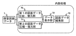
図18は顧客端末63の機能に基づく構成を示すブロック図であり、第1の図面データ圧縮・復元部70、第2の図面データ圧縮・復元部71、データ表示部72、図面データ編集部73から構成されている。
【0069】
第1の図面データ圧縮・復元部70は、ハフマン符号化法などで圧縮されたファイルを元のファイルに復元する機能と、再度圧縮する機能を有する。第2の図面データ圧縮・復元部71は、ランレングス符号化法などで圧縮されたファイルを元のファイルに復元する機能と、再度圧縮する機能を有する。なお、不可逆的手法で圧縮された第2の図面データを復元せずに用いる場合には、第2の図面データ圧縮・復元部71の機能を省略することも可能である。
【0070】
データ表示部72は第1の図面データと第2の図面データを異なった色あるいは濃度で重ねて表示する機能を有する。なお、第1の図面データと第2の図面データは異なる層(レイヤー)に保存し、必要に応じて片方だけを表示したり、あるいは左右に同じ場所を表示したりできるように構成することが望ましい。図面データ編集部73は第1の図面データを修正する機能を有する。このような機能はCADソフトで広く実現されている技術であり、ここでは説明は省略する。
【0071】
なお、本実施形態における図面データ提供システムは複数の顧客端末63a、63b、…と接続され、顧客との間で保管図面データ7を送受信できるように構成されているが、このような構成は従来より知られているインターネットなどのオンライン接続技術を用いて実現することが可能であり、ここでは説明は省略する。また、セキュリティ上の観点から、図面データ提供システムを構成するホスト端末60とオンライン接続手段62との間には顧客端末63以外からの不正な侵入を防止するためのファイヤーウオールを設置するとともに、顧客端末63との通信には暗号を用いたりすることも一般的な技術であるので、その説明は省略する。
【0072】
顧客は会社、工事現場、出張先等から顧客端末63aを用いて図面データ提供システムを構成するホスト端末60にアクセスし、磁気ディスク装置61に格納された保管図面データ7を入手する。この保管図面データ7は、上で説明したように、データ量が従来のものより大幅に少なくなっている。したがって保管図面データ7の転送に要する時間は短かいもので済む。保管図面データ7は、テキストファイなどの形式による第1の図面データとイメージデータ形式による第2の図面データから構成されており、第1の図面データは第1の図面データ圧縮・復元部70で復元され、第2の図面データは第2の図面データ圧縮・復元部71で復元されてデータ表示部72に送られる。データ表示部72では、第1の図面データと第2の図面データをディスプレイなどに所定の方法で表示する。顧客はその表示を見ながら、例えば工事の内容に対応して第1の図面データを編集する。編集された第1の図面データは第1の図面データ圧縮・復元部70で圧縮されてホスト端末60に送信される。ホスト端末60は図面更新のバージョン管理をするとともに、修正された第1の図面データのファイルを磁気ディスク61に記憶する。第2の図面データも修正する場合には、同様の方法で修正し、ホスト端末60に送信すれば良い。
【0073】
本実施形態によれば、扱う電子化図面のデータ量が大幅に削減されているので、その保管に必要なファイルのサイズが格段に小さなもので済み、またデータの転送に必要な時間を大幅に短くすることができる。
【0074】
【発明の効果】
以上説明したように本発明では、文字、記号、線分などが混在する図面を電子化して保管するについて、文字列で記述される形式の第1の図面データとイメージデータ形式の第2の図面データの2本立てで行うようにしている。このため本発明によれば、電子化図面の保管に必要なファイルサイズを大幅に削減でき、しかも情報の欠落を有効に防止できる。
【図面の簡単な説明】
【図1】第1の実施形態による図面の電子化保管システムの機能に基づく全体構成を示す図である。
【図2】第1の実施形態による図面の電子化保管システムの機器的な構成を示す図である。
【図3】差分処理における各データの例を模式化して示す図である。
【図4】第1の実施形態による図面の電子化保管方法における処理の手順を示す図である。
【図5】原図面イメージデータの例を示す図である。
【図6】第1の図面データの例を示す図である。
【図7】ノイズ除去前の差分イメージデータの例を示す図である。
【図8】ノイズ除去後の差分イメージデータの例を示す図である。
【図9】保管図面データの構成例を示す図である。
【図10】本発明におけるファイルサイズの削減程度を従来のそれと比較したグラフを示す図である。
【図11】第2の実施形態による図面の電子化保管システムにおける第1の図面データ作成部の機能に基づく構成を示す図である。
【図12】第2の実施形態による図面の電子化保管方法における処理の手順を示す図である。
【図13】第3の実施形態による図面の電子化保管システムにおける第1の図面データ作成部の機能に基づく構成を示す図である。
【図14】第3の実施形態による図面の電子化保管方法で得られる保管図面データの構成例を示す図である。
【図15】第4の実施形態による図面の電子化保管方法で扱うの図面の例を示す図である。
【図16】第4の実施形態による図面の電子化保管方法における処理の手順を示す図である。
【図17】一実施形態による図面データ提供システムの全体構成の例を示す図である。
【図18】顧客端末の機能に基づく構成を示す図である。
【符号の説明】
1 原図面イメージデータ
2 第1の図面データ作成部(第1の図面データ作成手段)
3 第2の図面データ作成部(第2の図面データ作成手段)
4 第1の図面データ圧縮部(圧縮手段)
5 第2の図面データ圧縮部(圧縮手段)
6 データ記憶部
10 イメージ入力装置
11 磁気ディスク装置(記憶手段)
21 イメージデータ記憶部
22 線分抽出部(線分抽出手段)
23 文字抽出部(文字抽出手段)
24 記号抽出部(記号抽出手段)
25 図面データ変換処理部
31 イメージデータ変換部(差分取得用イメージデータ作成手段)
32 差分処理部(差分イメージデータ作成手段)
33 ノイズ除去部(ノイズ除去手段)
34 図面データ取得部
40、41、42 信頼度評価部(信頼度評価手段)
50 統合認識部(統合認識手段)
60 ホスト端末(電子化図面保管手段)
61 磁気ディスク装置(電子化図面保管手段)
62 通信手段
63 顧客端末
70 第1の図面データ圧縮・復元部
71 第2の図面データ圧縮・復元部
72 データ表示部
73 図面データ編集部[0001]
BACKGROUND OF THE INVENTION
The present invention relates to a method and system for digitizing and storing drawings in which characters, symbols, and line segments are mixed, and a system for providing digitized drawing data.
[0002]
[Prior art]
With the spread of computer-supported document management, drawings that have been created in the past and stored in the form of paper drawings or drawings provided by other companies in the form of paper drawings are scanned and digitized. The electronic drawings can be stored, or a service for providing data of the electronic drawings is provided. As such an example, for example,
[0003]
In addition, after optically reading the information represented by characters, symbols, line segments, etc. in the drawing as an image, it is converted into electronic data that is described as a character string (described only by a character code). There is also known a method of converting and storing it as, for example, a text file or a binary file.
[0004]
[Patent Document 1]
JP 2001-350824 A
[Patent Document 2]
JP 2000-306103 A
[0005]
[Problems to be solved by the invention]
A method of storing and providing the entire drawing in an image data format, as in the technique disclosed in
[0006]
On the other hand, as in the technique disclosed in Patent Document 2, the method of digitizing the character area and the image area can reduce the amount of data because character data requires much less data than image data. It is valid. However, although the technique disclosed in Patent Document 2 is effective for normal documents in which a character area and an image area are easily separated, application to a design drawing in which characters, symbols, and line segments are mixed is not possible. Have difficulty.
[0007]
In addition, the above-described method of recognizing and extracting information contained in a drawing and converting it into electronic data described in character strings significantly reduces the amount of data compared to storing the drawing as image data. it can. However, existing paper drawings often include freehand handwritten portions. And such a part cannot be digitized in many cases, and there exists a problem that a lack of information arises for that. Moreover, even if it is not a handwritten part, a lack of information may occur due to recognition failure or misrecognition.
[0008]
The present invention has been made in the background as described above, and even if the drawing includes characters, symbols, and line segments and includes a handwritten portion, the information is not lost, and For the purpose of providing a computerized storage method and system for electronic drawings that can be stored electronically with a significantly smaller amount of data than when storing the whole as image data, and a system for providing electronic drawing data using them Yes.
[0009]
[Means for Solving the Problems]
In order to achieve one of the above objects, according to the present invention, in a method of storing a drawing electronically, characters, symbols, line segments, etc. included in the original drawing image data in the image data format for the drawing to be stored are stored. A step of extracting a standard drawing component, a step of creating first drawing data in a format described in a character string with respect to the extracted standard drawing component, and converting the first drawing data into image data Creating difference image data in a format, creating difference image data by taking a difference between the image data for difference acquisition and the original drawing image data, and a second image data format based on the difference image data A step of creating two drawing data, a process of storing the first drawing data and the second drawing data in the storage means as archive drawing data It is characterized in that it contains.
[0010]
In the present invention, the electronic storage method for drawings as described above further includes a step of evaluating the reliability of extraction of the standard drawing components, and only the standard drawing components having the reliability equal to or higher than a predetermined value are included. Is taken into the first drawing data diagram.
[0011]
In the present invention, the electronic storage method for drawings as described above further includes an integrated recognition step for recognizing the correspondence, explanation, and connection between the standard drawing components.
[0012]
In the present invention, the electronic storage method of the drawing as described above further includes a step of removing noise from the difference image data.
[0013]
According to the present invention, in the electronic storage method for drawings as described above, only the remaining drawing information is partially extracted from the difference image data to create the second drawing data.
[0014]
In the present invention, the electronic storage method for drawings as described above further includes a step of compressing the first drawing data and the second drawing data.
[0015]
In the present invention, the drawing information common to a plurality of drawings to be stored is stored as a separate file in the electronic storage method for drawings as described above.
[0016]
According to the present invention, in the electronic storage method for drawings as described above, a criterion is set for the standard drawing component, and only the standard drawing component that satisfies the criterion is obtained from the original drawing image data. I try to extract.
[0017]
In the present invention, in order to achieve another one of the above objects, in a system for electronically storing a drawing, characters and symbols included in the original drawing image data in an image data format for the drawing to be stored Means for extracting a standard drawing component such as a line segment, means for generating first drawing data in a format described in a character string with respect to the extracted standard drawing component, and the first drawing data Means for creating image data for difference acquisition in an image data format by conversion, means for creating difference image data by taking a difference between the image data for difference acquisition and the original drawing image data, based on the difference image data Means for creating second drawing data in an image data format, wherein the first drawing data and the second drawing data are stored as archive drawing data; It is characterized in that it comprises means for.
[0018]
According to the present invention, the electronic storage system for drawings as described above further comprises means for evaluating the reliability of extraction of the standard drawing components, and only the standard drawing components having the reliability equal to or higher than a predetermined value. Is taken into the first drawing data.
[0019]
In the present invention, the electronic storage system for drawings as described above is further provided with integrated recognition means for recognizing correspondences, explanation relationships, and connection relationships between the standard drawing components.
[0020]
In the present invention, the electronic storage system for drawings as described above further includes means for compressing the first drawing data and the second drawing data.
[0021]
According to the present invention, in order to achieve another one of the objects, in the system for providing digitized drawing data, means for storing the digitized drawing by the digitized storage method for a drawing as described above is provided. In addition to being provided on the drawing provider side, a customer terminal connected to the means for storing the electronic drawing via a communication means is provided on the customer side.
[0022]
According to the present invention, in the drawing data providing system as described above, the first drawing data compression / decompression means, the second drawing data compression / decompression means, the first drawing data providing system, Means for displaying drawing data and second drawing data, means for editing the first drawing data, and means for transmitting the result of the editing to the storage means on the drawing provider side are provided.
[0023]
DETAILED DESCRIPTION OF THE INVENTION
Hereinafter, embodiments of the present invention will be described with reference to the drawings. FIG. 1 is a block diagram showing an overall configuration based on the functions of a system used for carrying out the electronic storage method for drawings according to the first embodiment of the present invention, and FIG. 2 is a diagram showing the overall configuration of the device. It is.
[0024]
In the computerized storage method or system for drawings according to the present invention, there are a case where a drawing in the form of a paper drawing is digitized and a case where a drawing that has already been digitized is stored. In other words, in the present invention, first, the original
[0025]
The computerized drawing storage system according to the present embodiment includes a first drawing data creation unit 2, a second drawing
[0026]
The first drawing data creation unit 2 includes an image
[0027]
The second drawing
[0028]
The
[0029]
FIG. 3 shows an example of each data in the difference processing. (A) is the original drawing image data, (b) is the difference acquisition image data, and (c) is the difference image data. In the difference processing, when the pixel of the original drawing image data is 0 (black) and the pixel of the difference acquisition image data is 1 (white), the pixel of the difference image data is set to 0.
[0030]
The
[0031]
When the drawing information remains in the differential image data, the drawing data acquisition unit 34 extracts only the remaining drawing information portion in the image data format and creates second drawing data. In order to extract the remaining drawing information, the remaining drawing information part is cut out in the image data format to acquire partial image data, and the position information of the area where the remaining drawing information exists is acquired. A predetermined file name is assigned to each partial image data. That is, the second drawing data is created as data composed of partial image data specified by a predetermined file name and location information of the existing area. The second drawing data preferably includes resolution information related to the original
[0032]
The first drawing data compression unit 4 compresses the first drawing data. As described above, the first drawing data is created in, for example, a text data format. The Huffman coding method is known as a method for compressing text data, and since there are many softwares using these compression methods, they can be used.
[0033]
The second drawing
[0034]
The
[0035]
Here, as shown in FIG. 2, the electronic storage system of the drawing is not limited to the operator in addition to the
[0036]
Hereinafter, the entire implementation procedure will be described with reference to the flowchart of FIG. 4 and the explanatory diagrams of FIGS. 5 to 8. First, in
[0037]
Next, in
[0038]
In
[0039]
In
[0040]
In
[0041]
In
[0042]
In
[0043]
In
[0044]
In
[0045]
In
[0046]
In
[0047]
FIG. 9 shows an example of storage drawing data. The first drawing data includes information about line segments, symbols, and characters, which are the types and sizes of line segments, symbols, and characters (thickness in the case of line segments, Symbols and characters are described by names (
[0048]
FIG. 10 compares the degree of file size reduction in the present invention with that of the prior art. The conventional example to be compared is a case where the entire drawing is captured as image data and subjected to normal compression processing. The horizontal axis of FIG. 10 represents the ratio of the remaining drawing information area that could not be captured as the first drawing data to the total area of the drawing. When an A0 size paper drawing is converted to image data in a monochrome bitmap format at a resolution of 600 DPI, the file size is 60 MB (megabytes) or more, and the compression is about 1/15 that does not cause loss of information. Even if the compression process is applied, the size becomes 4 MB or more. On the other hand, in the present invention, first drawing data and second drawing data are created from image data (original drawing image data) obtained by optically reading a paper drawing, and both are stored as archive drawing data. In this case, the file size of the first drawing data varies depending on the complexity of the drawing and the conversion method. For example, it is relatively easy to approximate a circle or the like with a fine straight line, but with such a method, the file size of the first drawing data tends to be large. Therefore, something with high formality such as a circle is considered as one of the symbols. By doing so, in the case of a general A0 size drawing, the first drawing data can be reduced to 2 MB or less. Also, with respect to the second drawing data, only the remaining drawing information that could not be captured as the first drawing data is handled in the image data format, so that the file size can be reduced. Therefore, according to the present invention, it becomes possible to reduce the file size compared with the case where the entire drawing is stored as image data without any particular compression processing, and a compression of about 1/15 is combined. If so, the file size can be significantly reduced as seen in FIG. That is, even if the area that could not be captured as the first drawing data is about 30%, the file size is about 1/3 of the conventional example, and if it is about 10%, the file size is 1/8 of the conventional example. It will be about.
[0049]
In the first embodiment described above, the first drawing data and the second drawing data are combined and used as storage drawing data. Therefore, when the entire drawing is captured and stored in the image data format. In comparison, the file size of the stored drawing data can be reduced, and the loss of information can be prevented with high accuracy. In addition, since the first drawing data and the second drawing data are appropriately compressed, the file size can be further reduced. In addition, since noise removal processing is performed when the second drawing data is created, it is possible to avoid taking in excess image data. This also helps reduce file size. In addition, since elements common to a plurality of drawings are stored as separate files, the amount of data required to store the common elements can be reduced, and the file size can be further reduced.
[0050]
In the above embodiment, the original drawing image data is finally deleted. However, the original drawing image data is used as a backup for another storage device, for example, an optical disk device suitable for large-capacity storage. You may make it preserve | save. Although the first drawing data before compression is finally deleted, the uncompressed first drawing data file is saved as a text search file so that character strings and special characters in the drawing can be saved. You may make it utilize for the search of a symbol.
[0051]
Next, an electronic storage method or system for drawings according to the second embodiment will be described with reference to FIGS. FIG. 11 is a block diagram showing a configuration based on the function of the first drawing data creation unit in the system for carrying out the drawing electronic storage method according to the second embodiment. As seen in FIG. 11, the first drawing data creation unit in the present embodiment corresponds to each of the line
[0052]
The
[0053]
FIG. 12 is a flowchart of an implementation procedure in the second embodiment. First, in
[0054]
In
[0055]
In
[0056]
In the present embodiment, only standard drawing components whose reliability is higher than the reference value are converted into the first drawing data. Therefore, the drawing information that can be taken in as the first drawing data may be less than that in the first embodiment. However, according to the current recognition technology, there are not many cases where the reliability is lower than the reference value. Therefore, also in this embodiment, the file size in electronic storage of drawing information can be greatly reduced. In this embodiment, in addition to such a reduction in file size, there is an effect of further improving the accuracy of preventing information loss. In other words, there is a possibility that information loss may occur when taking the difference between the original drawing image data and the image data for difference acquisition, but the standard drawing configuration with a certain degree of recognition / extraction reliability as in the present embodiment is high. By converting only the elements into the first drawing data, the possibility of missing information at the time of obtaining the difference can be further reduced. In the present embodiment, only standard drawing components having a certain level of recognition / extraction reliability higher than a certain level are converted to the first drawing data, so that design changes are made based on the stored drawing data. There is also an effect that it becomes easy to correct the drawing at the time.
[0057]
Next, an electronic storage method or system for drawings according to a third embodiment will be described with reference to FIGS. FIG. 13 is a block diagram showing a configuration based on the function of the first drawing data creation unit in the system for carrying out the electronic storage method for drawings according to the second embodiment. As seen in FIG. 13, the first drawing data creation unit in the present embodiment is different from that in the second embodiment in that an
[0058]
FIG. 14 is a diagram illustrating a configuration example of archive drawing data created in the third embodiment. As can be seen by comparing the stored drawing data with the stored drawing data (FIG. 9) in the first embodiment, the stored drawing data in FIG. 14 includes attribute information in addition to the reliability information of standard drawing components. 1 is attached to the drawing data. This attribute information includes, for example, the contents of a character string describing the symbol. When an appropriate display program is used, the character string is clicked by clicking the symbol with the mouse 13 (FIG. 2). The contents can be shown. It is also possible to give an attribute indicating the connection relation of the line segment. When such an attribute is given, for example, by clicking “
[0059]
In the present embodiment, since the correspondence, explanation relationship, and connection relationship between standard drawing components are recognized, the data amount of the first drawing data is increased, but the amount is small. Even in the form, it is possible to greatly reduce the file size in electronic storage of drawings. In the present embodiment, in addition to the reduction of the file size, there are the following effects. First, the correspondence, explanation, and connection between standard drawing components are included in the first drawing data, so that the work can be more easily performed when the stored drawing data is manually checked as necessary. It can be done easily. Also, the attribute information can be used effectively when planning a maintenance or managing a maintenance history.
[0060]
Next, an electronic storage method or system for drawings according to the fourth embodiment will be described with reference to FIGS. 15 and 16. This embodiment is useful when a drawing such as the example shown in FIG. 15 is to be stored. The drawing of FIG. 15 includes piping 260, an
[0061]
FIG. 16 is a flowchart showing an implementation procedure in the present embodiment. In the present embodiment, any of the system configurations in the above embodiments can be used as the system configuration. In the following description, the system configuration in the first embodiment is used. First, in
[0062]
If it is an element to be converted, symbol recognition / extraction is executed in
[0063]
In
[0064]
When it is determined that it is necessary to leave image data, the processing from
[0065]
In the present embodiment, only the standard drawing components designated in advance are converted into the first drawing data in accordance with the characteristics of the drawing to be stored, so that the file size of the stored drawing data can be further reduced. Can do. In addition, the second drawing data is judged to be necessary and the image data is not stored when it is not necessary. Therefore, the file size of the stored drawing data can be further reduced, and the image data can be reduced. Even when the image data is stored, the image data compression rate can be increased, so that the file size reduction rate can be maintained high.
[0066]
Next, an embodiment of a drawing data providing system according to the present invention will be described with reference to FIGS. The drawing data providing system in the present embodiment is configured as a system for providing a user with stored drawing data created by the above-described electronic storage method for drawings.
[0067]
FIG. 17 is a diagram showing an example of the overall configuration of the drawing data providing system. In the drawing data providing system, a company that provides drawing data and a customer who receives the drawing data are members. Then, a
[0068]
18 is a block diagram showing a configuration based on the function of the customer terminal 63. The first drawing data compression /
[0069]
The first drawing data compression /
[0070]
The
[0071]
The drawing data providing system in the present embodiment is connected to a plurality of
[0072]
The customer accesses the
[0073]
According to this embodiment, since the amount of data of the electronic drawings to be handled is greatly reduced, the size of the file required for storage can be much smaller, and the time required for data transfer can be greatly reduced. Can be shortened.
[0074]
【The invention's effect】
As described above, according to the present invention, the first drawing data in the format described in the character string and the second drawing in the image data format are used for storing the drawings in which characters, symbols, line segments, etc. are mixed and stored in an electronic form. I do it in two sets of data. Therefore, according to the present invention, the file size necessary for storing the electronic drawing can be greatly reduced, and the loss of information can be effectively prevented.
[Brief description of the drawings]
FIG. 1 is a diagram showing an overall configuration based on functions of an electronic storage system for drawings according to a first embodiment.
FIG. 2 is a diagram showing a device configuration of the electronic storage system for drawings according to the first embodiment.
FIG. 3 is a diagram schematically illustrating an example of each data in difference processing.
FIG. 4 is a diagram showing a processing procedure in the electronic storage method for drawings according to the first embodiment.
FIG. 5 is a diagram showing an example of original drawing image data.
FIG. 6 is a diagram illustrating an example of first drawing data.
FIG. 7 is a diagram illustrating an example of difference image data before noise removal.
FIG. 8 is a diagram illustrating an example of difference image data after noise removal.
FIG. 9 is a diagram illustrating a configuration example of storage drawing data.
FIG. 10 is a graph showing a comparison of the degree of file size reduction in the present invention with that of the prior art.
FIG. 11 is a diagram illustrating a configuration based on a function of a first drawing data creation unit in the electronic drawing storage system according to the second embodiment;
FIG. 12 is a diagram showing a processing procedure in the electronic storage method for drawings according to the second embodiment.
FIG. 13 is a diagram showing a configuration based on a function of a first drawing data creation unit in an electronic drawing storage system according to a third embodiment.
FIG. 14 is a diagram showing a configuration example of storage drawing data obtained by the electronic storage method for drawings according to the third embodiment.
FIG. 15 is a diagram showing an example of a drawing handled by the electronic storage method for a drawing according to the fourth embodiment.
FIG. 16 is a diagram showing a processing procedure in the electronic storage method for drawings according to the fourth embodiment.
FIG. 17 is a diagram illustrating an example of the overall configuration of a drawing data providing system according to an embodiment.
FIG. 18 is a diagram illustrating a configuration based on a function of a customer terminal.
[Explanation of symbols]
1 Original drawing image data
2 First drawing data creation unit (first drawing data creation means)
3 Second drawing data creation unit (second drawing data creation means)
4 1st drawing data compression part (compression means)
5 Second drawing data compression unit (compression means)
6 Data storage
10 Image input device
11 Magnetic disk device (storage means)
21 Image data storage
22 Line segment extraction unit (line segment extraction means)
23 Character extraction part (character extraction means)
24 Symbol extraction unit (symbol extraction means)
25 Drawing data conversion processor
31 Image data conversion unit (difference acquisition image data creation means)
32 Difference processing unit (difference image data creation means)
33 Noise removal unit (noise removal means)
34 Drawing data acquisition unit
40, 41, 42 Reliability evaluation unit (reliability evaluation means)
50 Integrated recognition unit (Integrated recognition means)
60 Host terminal (electronic drawing storage means)
61 Magnetic disk unit (electronic drawing storage means)
62 Communication means
63 Customer terminal
70 First drawing data compression / decompression unit
71 Second drawing data compression / decompression unit
72 Data display section
73 Drawing Data Editor
Claims (14)
Priority Applications (1)
| Application Number | Priority Date | Filing Date | Title |
|---|---|---|---|
| JP2003206408A JP4101712B2 (en) | 2003-08-07 | 2003-08-07 | Electronic drawing storage method, electronic drawing storage system, and drawing data providing system |
Applications Claiming Priority (1)
| Application Number | Priority Date | Filing Date | Title |
|---|---|---|---|
| JP2003206408A JP4101712B2 (en) | 2003-08-07 | 2003-08-07 | Electronic drawing storage method, electronic drawing storage system, and drawing data providing system |
Publications (2)
| Publication Number | Publication Date |
|---|---|
| JP2005055996A JP2005055996A (en) | 2005-03-03 |
| JP4101712B2 true JP4101712B2 (en) | 2008-06-18 |
Family
ID=34363282
Family Applications (1)
| Application Number | Title | Priority Date | Filing Date |
|---|---|---|---|
| JP2003206408A Expired - Fee Related JP4101712B2 (en) | 2003-08-07 | 2003-08-07 | Electronic drawing storage method, electronic drawing storage system, and drawing data providing system |
Country Status (1)
| Country | Link |
|---|---|
| JP (1) | JP4101712B2 (en) |
Families Citing this family (5)
| Publication number | Priority date | Publication date | Assignee | Title |
|---|---|---|---|---|
| JP2008097412A (en) * | 2006-10-13 | 2008-04-24 | Tokyo Electric Power Co Inc:The | Graphical user interface, drawing data management device and drawing data management method |
| JP2009211521A (en) * | 2008-03-05 | 2009-09-17 | Mitsubishi Electric Corp | Terrestrial object information management system |
| JP2014021658A (en) * | 2012-07-17 | 2014-02-03 | Mitsubishi Electric Corp | Ledger management system |
| JP2020047160A (en) * | 2018-09-21 | 2020-03-26 | 日本電設工業株式会社 | Estimation work support system and estimation work support program |
| EP3660731B1 (en) * | 2018-11-28 | 2024-05-22 | Tata Consultancy Services Limited | Digitization of industrial inspection sheets by inferring visual relations |
-
2003
- 2003-08-07 JP JP2003206408A patent/JP4101712B2/en not_active Expired - Fee Related
Also Published As
| Publication number | Publication date |
|---|---|
| JP2005055996A (en) | 2005-03-03 |
Similar Documents
| Publication | Publication Date | Title |
|---|---|---|
| CN109933756B (en) | Image file transferring method, device and equipment based on OCR (optical character recognition), and readable storage medium | |
| US8320019B2 (en) | Image processing apparatus, image processing method, and computer program thereof | |
| US7593961B2 (en) | Information processing apparatus for retrieving image data similar to an entered image | |
| US7391917B2 (en) | Image processing method | |
| JP5528121B2 (en) | Image processing apparatus, image processing method, and program | |
| JP2957375B2 (en) | Data processing system and method for correcting character recognition errors in digital images of document format | |
| US5963966A (en) | Automated capture of technical documents for electronic review and distribution | |
| US8045801B2 (en) | Image processing apparatus and method | |
| US7640269B2 (en) | Image processing system and image processing method | |
| US20060114485A1 (en) | Image processing apparatus, method thereof, and its control method | |
| US7746341B2 (en) | System and method for parsing point-cloud data | |
| JPH11338976A (en) | Document image recognition device, method therefor, and recording medium | |
| CN101820489A (en) | Image processing equipment and image processing method | |
| US20060008113A1 (en) | Image processing system and image processing method | |
| US7420150B2 (en) | Image processing apparatus, image processing method, and computer program | |
| US11501344B2 (en) | Partial perceptual image hashing for invoice deconstruction | |
| JPH09223240A (en) | Document electronizing device | |
| JP2005135211A (en) | Method and apparatus for managing document | |
| US6360006B1 (en) | Color block selection | |
| JPH08147446A (en) | Electronic filing device | |
| JP4101712B2 (en) | Electronic drawing storage method, electronic drawing storage system, and drawing data providing system | |
| US20090083316A1 (en) | Information processing apparatus, information processing method, and information processing program | |
| JP2005259017A (en) | Image processing apparatus, image processing program and storage medium | |
| US20100202025A1 (en) | Image processing apparatus, image processing method, program, and storage medium | |
| JP2008028716A (en) | Image processing method and apparatus |
Legal Events
| Date | Code | Title | Description |
|---|---|---|---|
| A621 | Written request for application examination |
Free format text: JAPANESE INTERMEDIATE CODE: A621 Effective date: 20050809 |
|
| TRDD | Decision of grant or rejection written | ||
| A01 | Written decision to grant a patent or to grant a registration (utility model) |
Free format text: JAPANESE INTERMEDIATE CODE: A01 Effective date: 20080318 |
|
| A61 | First payment of annual fees (during grant procedure) |
Free format text: JAPANESE INTERMEDIATE CODE: A61 Effective date: 20080319 |
|
| FPAY | Renewal fee payment (event date is renewal date of database) |
Free format text: PAYMENT UNTIL: 20110328 Year of fee payment: 3 |
|
| R150 | Certificate of patent or registration of utility model |
Free format text: JAPANESE INTERMEDIATE CODE: R150 |
|
| FPAY | Renewal fee payment (event date is renewal date of database) |
Free format text: PAYMENT UNTIL: 20110328 Year of fee payment: 3 |
|
| FPAY | Renewal fee payment (event date is renewal date of database) |
Free format text: PAYMENT UNTIL: 20120328 Year of fee payment: 4 |
|
| FPAY | Renewal fee payment (event date is renewal date of database) |
Free format text: PAYMENT UNTIL: 20130328 Year of fee payment: 5 |
|
| FPAY | Renewal fee payment (event date is renewal date of database) |
Free format text: PAYMENT UNTIL: 20130328 Year of fee payment: 5 |
|
| LAPS | Cancellation because of no payment of annual fees |