JP4101323B2 - Medical tube - Google Patents
Medical tube Download PDFInfo
- Publication number
- JP4101323B2 JP4101323B2 JP09708497A JP9708497A JP4101323B2 JP 4101323 B2 JP4101323 B2 JP 4101323B2 JP 09708497 A JP09708497 A JP 09708497A JP 9708497 A JP9708497 A JP 9708497A JP 4101323 B2 JP4101323 B2 JP 4101323B2
- Authority
- JP
- Japan
- Prior art keywords
- balloon
- shaft tube
- cylindrical
- medical
- circumferential direction
- Prior art date
- Legal status (The legal status is an assumption and is not a legal conclusion. Google has not performed a legal analysis and makes no representation as to the accuracy of the status listed.)
- Expired - Fee Related
Links
Images


Description
【0001】
【発明の属する技術分野】
本発明は、検査や治療のために生体内に挿入するための、可変湾曲運動性の組織剥離機能を持った医療用チューブに関する。より詳しくは、加圧流体を注入した際のバルーンの部分的な伸展差を利用して可変湾曲運動性の組織剥離機能を持たせた医療用チューブに関する。
【0002】
【従来の技術】
過去において侵襲の大きかった手術も、現在では次第に低侵襲な手技に置き換わってきている。例えば、PTCAやPTA、ステント、アテレクトミー、塞栓術、内視鏡下手術など、カテーテル技術や内視鏡を基本とした低侵襲治療法が目を見張る広がりを見せている。
【0003】
特にカテーテル技術分野では血管、消化管、卵管、尿管などの体腔内の特定部位に、薬液あるいは輸液を供給したり、バルーンの拡張によって狭窄部を拡張したりする目的で様々なバルーンカテーテルが開発されている。しかしながら、一部の内視鏡下手術を除いて、カテーテルを利用する応用例は体腔内を対象としたものである。
【0004】
【発明が解決しようとする課題】
カテーテルの応用分野の広がりと共に、血管などの生体管腔を利用するアプローチに限定されないカテーテルアプローチ方法が望まれている。
カテーテルを生体管腔外から目的部位に到達させて治療を施すには、生体管腔内アプローチの場合とは異なり、まず様々な組織中に低摩擦で腔を形成しなければならない。このためには、時として組織を広範囲に剥離しなければならない場合もある。そして目的部位に到達した後に、カテーテルのマルチルーメンを利用して様々なツールを適応し、診断や治療を行う。
【0005】
組織を剥離する方法としては、カテーテルが剥離すべき組織の目的部位に到達した後、カテーテルの先端部を連続的に変形運動させることが考えられる。カテーテル先端部の湾曲操作の機構については様々な構造が提案されているが、いずれも複雑でカテーテルの大径化が避けられず、また、生体管腔外からのアプローチという視点に立って開発された多機能カテーテルは未だにみられない。
本発明は、このような従来技術の課題を解決するためになされたものであり、本発明の目的は、生体管腔外からのアプローチという視点に立って、可変湾曲運動性の生体組織の剥離機能を持った、単純な構造で細径化が可能な医療用チューブ構造を提供することにある。
【0006】
【課題を解決するための手段】
本発明者は上記の目的を達成するために種々検討の結果、筒状のバルーンの周方向の半分未満の部分にその軸方向の一部に延びた伸展性の小さい部分を少なくとも2か所設け、それらの伸展性の小さい部分を筒状バルーンの軸方向でずらして位置させ且つ筒状バルーンの周方向で反対側に位置させ、該バルーンの周方向で架橋度を変化させることにより該伸展性の小さい部分を形成し、そして該バルーン内に加圧流体を注入することにより、バルーンの伸展性の大きい側がより大きく膨張し、伸展性の小さい側があまり膨張しないので、該バルーンが伸展性の小さい部分側に湾曲してS字状になり、またその湾曲の程度は加圧流体の圧力によって調整でき、更に加圧流体の圧力をパルス状に変化させることにより、可変湾曲運動性の組織剥離機能が達成されることを見いだし、本発明を完成した。
【0007】
即ち、本発明の第一の態様は、生体内に挿入されるシャフト管と、該シャフト管の先端部外周に流体密に接合された筒状のバルーンと、該シャフト管内に設けられていて該バルーン内に連通している第一ルーメンと、該シャフト管内に設けられていて該シャフト管の先端に開口している少なくとも1個の第二ルーメンとを有し、該筒状のバルーンは、その周方向の半分未満の部分にその軸方向の一部に延びた伸展性の小さい部分を少なくとも2か所持っており、それらの伸展性の小さい部分は筒状バルーンの軸方向でずれて位置しており且つ筒状バルーンの周方向で反対側に位置し、該バルーンの周方向で架橋度を変化させることにより該伸展性の小さい部分が形成されていることを特徴とする医療用チューブである。
【0008】
また、本発明の第二の態様は、生体内に挿入されるシャフト管と、筒状のバルーンの一端が該シャフト管の先端に流体密に接合された該筒状のバルーンと、先端部が該筒状のバルーンの他端に直接又は間接的に流体密に接合された長尺な医療処置又は診断具と、該シャフト管内に設けられていて、該バルーン内に流体通過可能に連通しており、且つ該長尺な医療処置又は診断具を収容している第一ルーメンとを有し、該筒状のバルーンは、その周方向の半分未満の部分にその軸方向の一部に延びた伸展性の小さい部分を少なくとも2か所持っており、それらの伸展性の小さい部分は筒状バルーンの軸方向でずれて位置しており且つ筒状バルーンの周方向で反対側に位置し、該バルーンの周方向で架橋度を変化させることにより該伸展性の小さい部分が形成されていることを特徴とする医療用チューブである。
【0009】
更に、本発明の第三の態様は、生体内に挿入されるシャフト管と、筒状のバルーンの一端が該シャフト管の先端に流体密に接合された該筒状のバルーンと、先端部が該筒状のバルーンの他端に直接又は間接的に流体密に接合された長尺な医療処置又は診断具と、該シャフト管内に設けられていて、該バルーン内に流体通過可能に連通しており、且つ該長尺な医療処置又は診断具を収容している第一ルーメンと、該シャフト管内に設けられていて該シャフト管の先端部外周に開口している少なくとも1個の第二ルーメンとを有し、該筒状のバルーンは、その周方向の半分未満の部分にその軸方向の一部に延びた伸展性の小さい部分を少なくとも2か所持っており、それらの伸展性の小さい部分は筒状バルーンの軸方向でずれて位置しており且つ筒状バルーンの周方向で反対側に位置し、該バルーンの周方向で架橋度を変化させることにより該伸展性の小さい部分が形成されていることを特徴とする医療用チューブである。
【0010】
【発明の実施の形態】
以下に、本発明に係わる医療用チューブを、図面に示す実施様態に基づき、詳細に説明する。
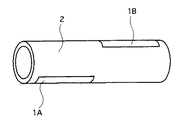
図1は本発明の医療用チューブに用いる筒状のバルーンの一例を示す斜視図であり、相対的に伸展性の小さい部分1と相対的に伸展性の大きい部分2とからなり、伸展性の小さい第一部分1Aが筒状バルーンの周方向の一部分でその軸方向の約半分の長さで延びており、伸展性の小さい第二部分1Bが筒状バルーンの周方向の一部分でその軸方向の約半分の長さで延びており、該第一部分1Aと該第二部分1Bとは筒状バルーンの周方向で反対側に存在し、筒状バルーンの軸方向でずれている。
【0011】
図1には伸展性の小さい部分が2か所ある筒状のバルーンを示したが、伸展性の小さい部分が3か所以上ある筒状のバルーンを用いることもできる。例えば、3か所ある場合には、伸展性の小さい第一部分が筒状バルーンの周方向の一部分でその軸方向の約1/3の長さで延びており、伸展性の小さい第二部分が筒状バルーンの周方向の一部分でその軸方向の約1/3の長さで延びており、伸展性の小さい第三部分が筒状バルーンの周方向の一部分でその軸方向の約1/3の長さで延びており、該第一部分と該第二部分とは筒状バルーンの周方向で反対側に存在し、第一部分と該第三部分とは筒状バルーンの周方向で同一側に存在し、それらは筒状バルーンの軸方向でずれて存在しているように構成すればよい。
この伸展性の差は、バルーンを構成する材質の延伸率、弾性率、剛性、硬度などの機械的物性値の差や、膜厚などの物理的物性値の差などによってもたらされる。
【0012】
本発明の医療用チューブに用いるバルーンの材質としては、例えば、天然ゴム、ポリエチレン、ポリプロピレン、エチレン−プロピレン共重合体、エチレンー酢酸ビニル共重合体、軟質ポリ塩化ビニル、ポリウレタン、ポリイソプレン、ポリアミド、ポリアミドエラストマー、ポリイミド、ポリイミドエラストマー、シリコーンなどが挙げられ、好ましくは天然ゴム、ポリエチレン、軟質ポリ塩化ビニル、シリコーンのような可撓性を有する高分子材料が用いられる。更に好ましくは、低密度ポリエチレンである。なお、これらの材料は放射線架橋性のものである。
【0013】
上記の伸展性の小さい部分1A、1Bは、バルーンの周方向の隣接する部分で連続的に変化していてもよいし、段階的に変化していてもよく、この伸展性の小さい部分1A、1Bは好ましくは全周の30%以下、より好ましくは10%以下である。また、この伸展性の小さい部分1A、1Bは、所望の湾曲度に応じて、バルーンの軸方向の一部又は全体にわたって連続して延びていても、断続的に設けられていてもよい。
【0014】
上記のような部分的に伸展性に差のあるバルーンは、例えば、バルーンの膜厚を周方向で変化させて成形するか、物性値の異なる2種の樹脂を用いて成形することにより得られるが、好ましくは、バルーンの周方向で架橋度が変化するように放射線架橋処理を施すことにより得られる。
尚、放射線架橋処理は、例えば電子線、γ線等の高エネルギー線(特殊な場合にはX線、β線、重荷電粒子線、中性子線等を含む)、紫外線等を照射することによって実施することができる。
【0015】
放射線架橋処理として電子線架橋処理を実施して部分的に伸展性に差のあるバルーンを製造する場合について説明すると、例えば、低密度ポリエチレンを用いてバルーンを成形し、バルーンの周方向で電子線架橋量を変化させることによって伸展性を変化させる。好ましくは、バルーンの伸展性の大きい部分2には電子線照射量が5〜35Mradとなるように照射し、伸展性の小さい部分1A、1Bには、伸展性の大きい部分2の電子線照射量よりも3〜10Mrad多くなるように照射する。更に好ましくは、バルーンの伸展性の大きい部分2には電子線照射量が20〜25Mradとなるように照射し、伸展性の小さい部分1A、1Bには、伸展性の大きい部分2の電子線照射量よりも3〜5Mrad多くなるように照射する。
【0016】
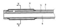
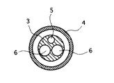
図2は本発明の第一の態様の医療用チューブの一部分の断面図であり、図3は図2中の III−III線断面図である。図2〜図3に示すように、本発明の第一の態様の医療用チューブは、生体内に挿入されるシャフト管3と、該シャフト管3の先端部外周に流体密に接合された筒状のバルーン4とを有している。該シャフト管3内には該バルーン4内に連通している第一ルーメン5が設けられており、更に、該シャフト管3の先端に開口している少なくとも1個の第二ルーメン6が設けられている。本発明においては該筒状のバルーン4は図1に関連して説明した特殊な形状、特性を有しているものである。
【0017】
上記のシャフト管3は、例えば、ポリエチレン、ポリエチレンテレフタレート、軟質ポリ塩化ビニル、ポリプロピレン、ポリウレタン、ポリアミド、ポリイミド、ポリテトラフルオロエチレン、シリコーンゴム、エチレンー酢酸ビニル共重合体のような可撓性を有する高分子材料で構成されている。
また、医療用チューブの挿入時の体腔等に対する摺動性を向上させるために、シャフト管3及びバルーン4の各々の外表面に、例えば親水性ポリマー(例えば無水マレイン酸共重合体)やフッ素系樹脂(例えばポリテトラフルオロエチレン)のような低摩擦材料をコーティングしてもよい。
【0018】
本発明の第一の態様の医療用チューブにおいては、シャフト管3の外周面近傍に、シャフト管3の一部または全長にわたり、各ルーメン5、6を囲むように管状の補強材を埋設することが好ましい。この補強材の材料としては、例えば、ステンレス、超弾性合金等の金属材料や、ポリアミド、ポリエチレン、ポリプロピレン、ポリエステル、ポリイミド、ABS樹脂等の樹脂材料、カーボンファイバー等よりなる線状体で構成されたもの、特にこの線状体を交差させて網状に形成した編組体で構成きれたものが好ましい。このような補強材の設置により、シャフト管3のねじり剛性が高まり、基端部側での回転操作の際、その回転力が先端部側へ伝達されるトルク伝連性が向上する。さらに、シャフト管3が湾曲しても、特に急角度に湾曲しても、それに伴ってルーメン5、6が閉塞または狭窄することが防止される。
【0019】
また、上記のシャフト管3が生体内に挿入されている状態でその位置をX線透視下で確認できるようにするために、シャフト管3にX線造影性を付与しておくことが好ましく、その方法としては、例えば、シャフト管3の構成材料中に例えば硫酸バリウム、酸化ビスマス、タングステン等のX線不透過性物質を配合する方法、このようなX線不透過性物質によるマーカーをシャフト管3の所定位置に埋設または表面に付着させる方法等が挙げられる。
【0020】
本発明の第一の態様の医療用チューブにおいては、医療用チューブの使用時に、バルーン内に連通している第一ルーメン5を流体圧力コントローラを介して加圧流体源に連結し、また、パルス状圧力発生用拍動ポンプを用いてパルス状圧力をバルーンに付与する。この加圧流体は気体であっても、液体であってもよい。流体圧力コントローラによる調整圧力範囲は好ましくは0〜15atmであり、この圧力に対応してS字状の湾曲角度が任意に変化する。また、この圧力に更に極小値圧0atm、極大値圧1〜5atmのパルス状圧力が付加されるので、S字状の湾曲運動が生じる。パルス状圧力が極小値圧の時にはバルーンはS字状にはならず、極大値圧の時にはバルーンはS字状になることが好ましい。バルーン.付与するパルス周波数は生体組織の剥離に要するエネルギーに依存するが、一般的には好ましくは1〜20Hzである。流体圧力コントローラの調整は手動式でも電動式であってもよい。
【0021】
本発明の第一の態様の医療用チューブにおいては、シャフト管の先端に開口している少なくとも1個の第二ルーメン6はガイドワイヤー、医療処置又は診断具等の挿通用チャンネルとして用いることができる。用いることのできる医療処置又は診断具としては、例えば、内視鏡、鉗子類、各種処置具、細胞診ブラシ、注射針、高周波、超音波、水圧衝撃波等を発する(結石破砕用、レーザー照射用、アブレーション用等の)プローブ類、各種センサー及びその導線等を挙げることができる。
【0022】
また、上記の医療処置又は診断具等とルーメン壁との間の間隙を用いて、あるいは別個の第二ルーメン6を用いて、生体組織、管状器官内に流体を注入したり、あるいは、流体を吸引したりすることができる。具体的には、医療用チューブを挿入し、留置した生体組織、管状器官内へ薬液等を投与するのに用いられ、あるいは、内視鏡により生体組織や管状器官内を観察する場合に、視界の妨げとなる血液、胆汁等の体液を押し出すための透明液体(例えば、生理食塩水、ぶどう糖液)を噴射するフラッシュ用チャンネルとしても用いられる。
【0023】
図2及び図3に示した医療用チューブにおいては、1個の第二ルーメン6を有しているが、本発明の医療用チューブにおいては、その用途に応じて図4に示すように2個の第二ルーメン6を有していても、あるいはそれ以上の第二ルーメン6を有していてもよい。そのように多数のルーメンを有するシャフト管及びその製造方法は従来技術で公知である。
【0024】
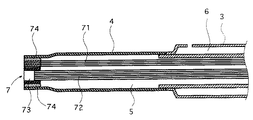
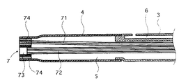
図5は本発明の第二の態様の医療用チューブの一部分の断面図である。本発明の第二の態様の医療用チューブは、生体内に挿入されるシャフト管3と、筒状のバルーン4の一端が該シャフト管3の先端に流体密に接合された該筒状のバルーン4と、先端部が該筒状のバルーン4の他端に直接又は間接的に流体密に接合された長尺な医療処置又は診断具7とを有している。該シャフト管3内には該バルーン内に流体通過可能に連通している第一ルーメン5が設けられており、該第一ルーメン5内には該長尺な医療処置又は診断具7が収容されている。該筒状のバルーン4は図1に関連して説明した特殊な形状、特性を有しているバルーンである。
【0025】
この医療処置又は診断具としては、例えば、内視鏡、鉗子類、各種処置具、細胞診ブラシ、高周波、超音波、水圧衝撃波等を発する(結石破砕用、レーザー照射用、アブレーション用等の)プローブ類、各種センサー及びその導線等を挙げることができる。
本発明の第二の態様における長尺な医療処置又は診断具7と筒状のバルーン4との接合法としては、両者を直接に接合させてもよく、又は両者の間に他のチューブを介在させて間接的に接合させても、或いは他のチューブを両者に跨がらせて間接的に接合させてもよい。
【0026】
なお、図5には、医療処置又は診断具7として、生体組織や管状器官内を観察する内視鏡を組み込んだ例が示されている。この内視鏡は送光用ファイバー束(ライトガイドファイバー束)71と、受光用ファイバー束(イメージファイバー束)72と、該受光用ファイバー束72の先端に装着されたレンズ73とを有している。該送光用ファイバー束71の先端部は該レンズ73を越えて医療用チューブの先端に延びている。そして、上記の筒状のバルーン4の他端(先端)は接着剤74により該送光用ファイバー束71及び該レンズ73に流体密に接合されている。
【0027】
本発明の第二の態様の医療用チューブにおいては、シャフト管の先端に開口するルーメンを持っていないので、生体組織、管状器官内に流体を注入したり、あるいは、流体を吸引したりすることはできない。しかし、医療用チューブの使用時に、バルーン4内に連通している第一ルーメン5を流体圧力コントローラを介して加圧流体源に連結し、パルス状圧力発生用拍動ポンプに連結することにより、図2及び図3に示した医療用チューブで説明したように、流体圧力コントローラ及びパルス状圧力発生用拍動ポンプによる調整圧力に対応して湾曲角度が任意に変化し、その湾曲の程度は流体圧力及びパルス状圧力に応じて連続的に変化させることができるので、生体組織を剥離しながら医療用チューブを押し進める方向を内視鏡で確認しながら正確に特定することができる。しかも、構造が極めて単純であり、極めて細い医療用チューブとすることができる。
【0028】
図6及び図7はそれぞれ本発明の第三の態様の医療用チューブの一部分の断面図である。本発明の第三の態様の医療用チューブは、生体内に挿入されるシャフト管3と、筒状のバルーン4の一端が該シャフト管3の先端に流体密に接合された該筒状のバルーン4と、先端部が該筒状のバルーン4の他端に直接又は間接的に流体密に接合された長尺な医療処置又は診断具7とを有している。該シャフト管3内には、該バルーン4内に流体通過可能に連通している第一ルーメン5が設けられており、更に、該シャフト管3の先端部外周に開口している少なくとも1個の第二ルーメン6が設けられている。また、該第一ルーメン5内には該長尺な医療処置又は診断具7が収容されている。
【0029】
この長尺な医療処置又は診断具は、本発明の第二の態様の医療用チューブについて上記で説明したものと同じであり、また、長尺な医療処置又は診断具7と筒状のバルーン4との接合法も上記で説明したものと同じである。図6及び図7もまた医療処置又は診断具7として、生体組織や管状器官内を観察する内視鏡を組み込んだ例を示しており、この内視鏡も上記で説明したものと同じである。
【0030】
本発明の第三の態様の医療用チューブにおいては、シャフト管3の先端部外周に開口するルーメンを持っているので、生体組織、管状器官内に流体を注入したり、あるいは、流体を吸引したりすることもでき、しかも、医療用チューブの使用時に、バルーン4内に連通している第一ルーメン5を流体圧力コントローラを介して加圧流体源に連結し、パルス状圧力発生用拍動ポンプに連結することにより、図2及び図3に示した医療用チューブで説明したように、流体圧力コントローラ及びパルス状圧力発生用拍動ポンプによる調整圧力に対応して湾曲角度が任意に変化し、その湾曲の程度は流体圧力に応じて連続的に変化させることができるので、生体組織を剥離しながら医療用チューブを押し進める方向を内視鏡で確認しながら正確に特定することができる。しかも、構造が極めて単純であり、極めて細い医療用チューブとすることができる。
【0031】
図8は、医療用チューブのバルーン4内に連通している第一ルーメン5を流体圧力コントローラを介して加圧流体源に連結し、パルス状圧力発生用拍動ポンプに連結し、バルーン4内に流体をパルス状に注入して、バルーンを相対的に伸展性の小さい部分側に湾曲させてS字状に湾曲させた状態を示している。その湾曲の程度は流体圧力に応じて連続的に変化させることができる。
以上、本発明の医療用チューブを図示の実施の形態に基づき説明したが、本発明はこれに限定されるものではない。
【0032】
【発明の効果】
以上述べたように本発明の医療用チューブは、複雑な構造体を用いる必要がなく、細径化が可能であり、可変湾曲運動性の生体組織の剥離機能を持った医療用チューブ構造を提供することができる。
【図面の簡単な説明】
【図1】 本発明の医療用チューブに用いる筒状のバルーンの斜視図である。
【図2】 本発明の第一の態様の医療用チューブの一部分の断面図である。
【図3】 図2中の III−III 線断面図である。
【図4】 本発明の第一の態様の医療用チューブの他の例を示す断面図である。
【図5】 本発明の第二の態様の医療用チューブの一部分の断面図である。
【図6】 本発明の第三の態様の医療用チューブの一部分の断面図である。
【図7】 本発明の第三の態様の医療用チューブの他の例を示す断面図である。
【図8】 本発明の医療用チューブのバルーンがS字状に湾曲した状態を示す断面図である。
【符号の説明】
1 相対的に伸展性の小さい部分
2 相対的に伸展性の大きい部分
3 シャフト管
4 筒状のバルーン
5 第一ルーメン
6 第二ルーメン
7 長尺な医療処置又は診断具
71 送光用ファイバー束
72 受光用ファイバー束
73 レンズ
74 接着剤[0001]
BACKGROUND OF THE INVENTION
The present invention relates to a medical tube having a variable bending motion tissue peeling function for insertion into a living body for examination or treatment. More specifically, the present invention relates to a medical tube having a tissue bending function of variable bending movement utilizing a partial extension difference of a balloon when a pressurized fluid is injected.
[0002]
[Prior art]
Surgery, which has been highly invasive in the past, is now gradually replaced by minimally invasive procedures. For example, minimally invasive treatment methods based on catheter technology and endoscopes such as PTCA, PTA, stents, atherectomy, embolization, and endoscopic surgery have shown remarkable spread.
[0003]
Especially in the field of catheter technology, various balloon catheters are used for the purpose of supplying medicinal solutions or infusions to specific sites in body cavities such as blood vessels, gastrointestinal tracts, fallopian tubes, and ureters, and expanding stenosis by expanding balloons. Has been developed. However, with the exception of some endoscopic operations, application examples that utilize catheters are intended for body cavities.
[0004]
[Problems to be solved by the invention]
Along with the expansion of the application field of catheters, a catheter approach method that is not limited to an approach using a living body lumen such as a blood vessel is desired.
In order to perform treatment by allowing the catheter to reach the target site from outside the living body lumen, unlike the case of the in-vivo approach, a cavity must first be formed in various tissues with low friction. This sometimes requires the tissue to be exfoliated extensively. After reaching the target site, various tools are applied using the multi-lumen of the catheter to perform diagnosis and treatment.
[0005]
As a method of exfoliating the tissue, it is conceivable that the distal end portion of the catheter is continuously deformed and moved after the catheter reaches the target site of the tissue to be exfoliated. Various structures have been proposed for the mechanism for bending the catheter tip, but they are all complicated and unavoidable to increase the diameter of the catheter, and have been developed from the viewpoint of an approach from outside the living body lumen. No multifunctional catheter has yet been found.
The present invention has been made to solve the above-described problems of the prior art, and the object of the present invention is to peel a living tissue with a variable bending motion from the viewpoint of an approach from outside the living body lumen. It is an object of the present invention to provide a medical tube structure that has a function and can be reduced in diameter with a simple structure.
[0006]
[Means for Solving the Problems]
As a result of various studies to achieve the above object, the present inventor provided at least two portions with small extensibility extending in a part in the axial direction in a portion of the cylindrical balloon less than half of the circumferential direction. The extensibility can be obtained by displacing the small extensibility portions in the axial direction of the cylindrical balloon and by locating them on the opposite side in the circumferential direction of the cylindrical balloon and changing the degree of crosslinking in the circumferential direction of the balloon. small portion was formed of, and by injecting the pressurized fluid into the balloon, inflated more largely side balloon extensibility large, the side small extensibility is not too inflated, smaller the balloon is a compliant Curved partly into an S shape, and the degree of curvature can be adjusted by the pressure of the pressurized fluid, and the tissue can be exfoliated with variable curvature by changing the pressure of the pressurized fluid in pulses. It found that ability is achieved, thereby completing the present invention.
[0007]
That is, the first aspect of the present invention is a shaft tube inserted into a living body, a cylindrical balloon fluidly joined to the outer periphery of the distal end portion of the shaft tube, and the shaft tube provided in the shaft tube. A first lumen that communicates with the balloon and at least one second lumen that is provided in the shaft tube and opens at a tip of the shaft tube; There are at least two parts with low extensibility extending in the axial direction in less than half of the circumferential direction, and these low extensibility parts are shifted in the axial direction of the cylindrical balloon. The medical tube is characterized in that it is located on the opposite side in the circumferential direction of the cylindrical balloon , and a portion having a low extensibility is formed by changing the degree of crosslinking in the circumferential direction of the balloon. .
[0008]
The second aspect of the present invention includes a shaft tube inserted into a living body, a cylindrical balloon in which one end of a cylindrical balloon is fluid-tightly joined to a distal end of the shaft tube, and a distal end portion. A long medical treatment or diagnostic tool directly or indirectly fluid-tightly joined to the other end of the cylindrical balloon is provided in the shaft tube and communicated with the balloon so that fluid can pass therethrough. And a first lumen containing the elongated medical procedure or diagnostic tool, and the cylindrical balloon extends to a part of its axial direction in a portion less than half of its circumferential direction There are at least two portions with low extensibility, and these low extensibility portions are offset in the axial direction of the cylindrical balloon and are positioned on the opposite side in the circumferential direction of the cylindrical balloon , Low extensibility by changing the degree of crosslinking in the circumferential direction of the balloon A medical tube, wherein the portion is formed.
[0009]
Furthermore, the third aspect of the present invention is the shaft tube inserted into the living body, the cylindrical balloon in which one end of the cylindrical balloon is fluid-tightly joined to the distal end of the shaft tube, and the distal end portion A long medical treatment or diagnostic tool directly or indirectly fluid-tightly joined to the other end of the cylindrical balloon is provided in the shaft tube and communicated with the balloon so that fluid can pass therethrough. And a first lumen housing the elongated medical procedure or diagnostic tool, and at least one second lumen provided in the shaft tube and opened to an outer periphery of a distal end portion of the shaft tube; The cylindrical balloon has at least two portions with low extensibility extending in a part in the axial direction in a portion less than half of the circumferential direction, and these portions with low extensibility Is offset in the axial direction of the cylindrical balloon and Located on the opposite side in the circumferential direction of the Jo balloon is a medical tube, wherein the small portion of該伸malleable by circumferentially varying the degree of crosslinking of the balloon is formed.
[0010]
DETAILED DESCRIPTION OF THE INVENTION
Below, the medical tube concerning this invention is demonstrated in detail based on the embodiment shown to drawing.
FIG. 1 is a perspective view showing an example of a cylindrical balloon used for the medical tube of the present invention, which is composed of a relatively low extensibility portion 1 and a relatively
[0011]
Although FIG. 1 shows a cylindrical balloon having two portions having low extensibility, a cylindrical balloon having three or more portions having low extensibility can also be used. For example, when there are three locations, the first portion having low extensibility extends in the circumferential direction of a part of the cylindrical balloon with a length of about 1/3 of the axial direction, and the second portion having low extensibility has A part of the cylindrical balloon extends in the circumferential direction with a length of about 1/3 of the axial direction, and the third part having low extensibility is a part of the cylindrical balloon in the circumferential direction and about 1/3 of the axial direction. The first part and the second part are on opposite sides in the circumferential direction of the cylindrical balloon, and the first part and the third part are on the same side in the circumferential direction of the cylindrical balloon. They exist and may be configured so as to be shifted in the axial direction of the cylindrical balloon.
This difference in extensibility is caused by differences in mechanical properties such as stretch ratio, elastic modulus, rigidity, and hardness of materials constituting the balloon, and differences in physical properties such as film thickness.
[0012]
Examples of the material of the balloon used for the medical tube of the present invention include natural rubber, polyethylene, polypropylene, ethylene-propylene copolymer, ethylene-vinyl acetate copolymer, soft polyvinyl chloride, polyurethane, polyisoprene, polyamide, polyamide. Examples include elastomers, polyimides, polyimide elastomers, silicones, and the like. Preferably, a polymer material having flexibility such as natural rubber, polyethylene, soft polyvinyl chloride, and silicone is used. More preferred is low density polyethylene. These materials are radiation crosslinkable.
[0013]
The
[0014]
A balloon having a difference in extensibility as described above can be obtained by, for example, molding by changing the film thickness of the balloon in the circumferential direction, or by molding using two kinds of resins having different physical property values. However, it is preferably obtained by performing a radiation crosslinking treatment so that the degree of crosslinking changes in the circumferential direction of the balloon.
The radiation cross-linking treatment is carried out by irradiating with high energy rays such as electron beams and γ rays (including X-rays, β rays, heavy charged particle rays, neutron rays in special cases), ultraviolet rays, etc. can do.
[0015]
An explanation will be given of a case where a balloon having a difference in extensibility is manufactured by carrying out an electron beam crosslinking treatment as a radiation crosslinking treatment. For example, a balloon is formed using low-density polyethylene, and an electron beam is formed in the circumferential direction of the balloon. The extensibility is changed by changing the amount of crosslinking. Preferably, the
[0016]
Figure 2 is a cross-sectional view of a portion of the medical tube of the first aspect of the present invention, FIG. 3 is a sectional view taken along line III-III in FIG. As shown in FIGS. 2 to 3, the medical tube according to the first aspect of the present invention includes a
[0017]
The
Further, in order to improve the slidability with respect to the body cavity or the like when the medical tube is inserted, for example, a hydrophilic polymer (for example, maleic anhydride copolymer) or a fluorine-based polymer is provided on the outer surface of each of the
[0018]
In the medical tube of the first aspect of the present invention, a tubular reinforcing material is embedded in the vicinity of the outer peripheral surface of the
[0019]
Further, in order to be able to confirm the position of the
[0020]
In the medical tube of the first aspect of the present invention, when the medical tube is used, the
[0021]
In the medical tube of the first aspect of the present invention, at least one
[0022]
In addition, a fluid is injected into a living tissue or a tubular organ using a gap between the above-described medical treatment or diagnostic tool or the like and a lumen wall, or using a separate
[0023]
The medical tube shown in FIGS. 2 and 3 has one
[0024]
FIG. 5 is a cross-sectional view of a portion of the medical tube of the second embodiment of the present invention. The medical tube of the second aspect of the present invention is a cylindrical balloon in which one end of a
[0025]
As this medical treatment or diagnostic tool, for example, an endoscope, forceps, various treatment tools, cytodiagnosis brush, high frequency, ultrasonic wave, hydraulic shock wave, etc. are emitted (for stone crushing, laser irradiation, ablation, etc.) Examples include probes, various sensors, and their lead wires.
As a joining method of the long medical treatment or
[0026]
FIG. 5 shows an example in which an endoscope for observing a living tissue or a tubular organ is incorporated as a medical procedure or
[0027]
The medical tube according to the second aspect of the present invention does not have a lumen that opens at the tip of the shaft tube, so that fluid is injected into a biological tissue or tubular organ, or fluid is aspirated. I can't. However, when the medical tube is used, the
[0028]
6 and 7 are cross-sectional views of a part of the medical tube according to the third embodiment of the present invention. The medical tube according to the third aspect of the present invention includes a cylindrical tube in which a
[0029]
The long medical treatment or diagnostic tool is the same as that described above for the medical tube of the second aspect of the present invention, and the long medical treatment or
[0030]
The medical tube according to the third aspect of the present invention has a lumen that opens to the outer periphery of the distal end portion of the
[0031]
FIG. 8 shows that a
As mentioned above, although the medical tube of this invention was demonstrated based on embodiment of illustration, this invention is not limited to this.
[0032]
【The invention's effect】
As described above, the medical tube of the present invention does not require a complicated structure, can be reduced in diameter, and provides a medical tube structure having a function of exfoliating a living body tissue with variable bending motion. can do.
[Brief description of the drawings]
FIG. 1 is a perspective view of a cylindrical balloon used for a medical tube of the present invention.
FIG. 2 is a cross-sectional view of a portion of the medical tube of the first aspect of the present invention.
FIG. 3 is a cross-sectional view taken along line III-III in FIG.
FIG. 4 is a cross-sectional view showing another example of the medical tube according to the first aspect of the present invention.
FIG. 5 is a cross-sectional view of a portion of the medical tube of the second aspect of the present invention.
FIG. 6 is a cross-sectional view of a portion of the medical tube of the third aspect of the present invention.
FIG. 7 is a cross-sectional view showing another example of the medical tube according to the third aspect of the present invention.
FIG. 8 is a cross-sectional view showing a state where the balloon of the medical tube of the present invention is curved in an S shape.
[Explanation of symbols]
DESCRIPTION OF SYMBOLS 1 Part with relatively
Claims (6)
該シャフト管の先端部外周に流体密に接合された筒状のバルーンと、
該シャフト管内に設けられていて該バルーン内に連通している第一ルーメンと、
該シャフト管内に設けられていて該シャフト管の先端に開口している少なくとも1個の第二ルーメンとを有し、
該筒状のバルーンは、その周方向の半分未満の部分にその軸方向の一部に延びた伸展性の小さい部分を少なくとも2か所持っており、それらの伸展性の小さい部分は筒状バルーンの軸方向でずれて位置しており且つ筒状バルーンの周方向で反対側に位置し、
該バルーンの周方向で架橋度を変化させることにより該伸展性の小さい部分が形成されていることを特徴とする医療用チューブ。A shaft tube inserted into the living body;
A cylindrical balloon fluid-tightly joined to the outer periphery of the tip of the shaft tube;
A first lumen provided in the shaft tube and in communication with the balloon;
At least one second lumen provided in the shaft tube and opening at a tip of the shaft tube;
The cylindrical balloon has at least two portions with low extensibility extending in a part in the axial direction in a portion less than half of the circumferential direction, and these low extensibility portions are cylindrical balloons. Is located in the axial direction and is located on the opposite side in the circumferential direction of the cylindrical balloon ,
A medical tube characterized in that a portion having a low extensibility is formed by changing the degree of crosslinking in the circumferential direction of the balloon .
筒状のバルーンの一端が該シャフト管の先端に流体密に接合された該筒状のバルーンと、
先端部が該筒状のバルーンの他端に直接又は間接的に流体密に接合された長尺な医療処置又は診断具と、
該シャフト管内に設けられていて、該バルーン内に流体通過可能に連通しており、且つ該長尺な医療処置又は診断具を収容している第一ルーメンとを有し、
該筒状のバルーンは、その周方向の半分未満の部分にその軸方向の一部に延びた伸展性の小さい部分を少なくとも2か所持っており、それらの伸展性の小さい部分は筒状バルーンの軸方向でずれて位置しており且つ筒状バルーンの周方向で反対側に位置し、
該バルーンの周方向で架橋度を変化させることにより該伸展性の小さい部分が形成されていることを特徴とする医療用チューブ。A shaft tube inserted into the living body;
The cylindrical balloon in which one end of the cylindrical balloon is fluid-tightly joined to the tip of the shaft tube;
A long medical treatment or diagnostic instrument having a tip part joined directly or indirectly fluid-tightly to the other end of the cylindrical balloon;
A first lumen provided in the shaft tube, in fluid communication with the balloon and containing the elongated medical procedure or diagnostic tool;
The cylindrical balloon has at least two portions with low extensibility extending in a part in the axial direction in a portion less than half of the circumferential direction, and these low extensibility portions are cylindrical balloons. Is located in the axial direction and is located on the opposite side in the circumferential direction of the cylindrical balloon ,
A medical tube characterized in that a portion having a low extensibility is formed by changing the degree of crosslinking in the circumferential direction of the balloon .
筒状のバルーンの一端が該シャフト管の先端に流体密に接合された該筒状のバルーンと、
先端部が該筒状のバルーンの他端に直接又は間接的に流体密に接合された長尺な医療処置又は診断具と、
該シャフト管内に設けられていて、該バルーン内に流体通過可能に連通しており、且つ該長尺な医療処置又は診断具を収容している第一ルーメンと、
該シャフト管内に設けられていて該シャフト管の先端部外周に開口している少なくとも1個の第二ルーメンとを有し、
該筒状のバルーンは、その周方向の半分未満の部分にその軸方向の一部に延びた伸展性の小さい部分を少なくとも2か所持っており、それらの伸展性の小さい部分は筒状バルーンの軸方向でずれて位置しており且つ筒状バルーンの周方向で反対側に位置し、
該バルーンの周方向で架橋度を変化させることにより該伸展性の小さい部分が形成されていることを特徴とする医療用チューブ。A shaft tube inserted into the living body;
The cylindrical balloon in which one end of the cylindrical balloon is fluid-tightly joined to the tip of the shaft tube;
A long medical treatment or diagnostic instrument having a tip part joined directly or indirectly fluid-tightly to the other end of the cylindrical balloon;
A first lumen provided in the shaft tube and in fluid communication with the balloon and containing the elongated medical procedure or diagnostic tool;
Having at least one second lumen provided in the shaft tube and open to an outer periphery of a tip portion of the shaft tube;
The cylindrical balloon has at least two portions with low extensibility extending in a part in the axial direction in a portion less than half of the circumferential direction, and these low extensibility portions are cylindrical balloons. Is located in the axial direction and is located on the opposite side in the circumferential direction of the cylindrical balloon ,
A medical tube characterized in that a portion having a low extensibility is formed by changing the degree of crosslinking in the circumferential direction of the balloon .
Priority Applications (6)
| Application Number | Priority Date | Filing Date | Title |
|---|---|---|---|
| JP09708497A JP4101323B2 (en) | 1997-04-15 | 1997-04-15 | Medical tube |
| US09/059,402 US6261260B1 (en) | 1997-04-15 | 1998-04-14 | Balloon for medical tube and medical tube equipped with the same |
| EP98400929A EP0872258B1 (en) | 1997-04-15 | 1998-04-15 | Balloon for medical tube and medical tube equipped with the same |
| DE69806533T DE69806533T2 (en) | 1997-04-15 | 1998-04-15 | Medical tube balloon |
| US09/803,021 US6478772B2 (en) | 1997-04-15 | 2001-03-12 | Method of inducing bending in a medical tube |
| US09/855,709 US6579260B2 (en) | 1997-04-15 | 2001-05-16 | Balloon for medical tube and medical tube equipped with the same |
Applications Claiming Priority (1)
| Application Number | Priority Date | Filing Date | Title |
|---|---|---|---|
| JP09708497A JP4101323B2 (en) | 1997-04-15 | 1997-04-15 | Medical tube |
Publications (2)
| Publication Number | Publication Date |
|---|---|
| JPH10286309A JPH10286309A (en) | 1998-10-27 |
| JP4101323B2 true JP4101323B2 (en) | 2008-06-18 |
Family
ID=14182784
Family Applications (1)
| Application Number | Title | Priority Date | Filing Date |
|---|---|---|---|
| JP09708497A Expired - Fee Related JP4101323B2 (en) | 1997-04-15 | 1997-04-15 | Medical tube |
Country Status (1)
| Country | Link |
|---|---|
| JP (1) | JP4101323B2 (en) |
Families Citing this family (11)
| Publication number | Priority date | Publication date | Assignee | Title |
|---|---|---|---|---|
| JP2001095923A (en) * | 1999-09-28 | 2001-04-10 | Terumo Corp | Catheter |
| EP1892007B1 (en) | 2005-06-14 | 2011-10-26 | Vayu Co., Ltd | Balloon catheter |
| JP2007181544A (en) * | 2006-01-06 | 2007-07-19 | Nipro Corp | Catheter set and forming method of its balloon |
| IL277376B (en) * | 2010-03-09 | 2022-08-01 | Smart Medical Systems Ltd | Balloon endoscope and methods of manufacture and use thereof |
| WO2012120492A1 (en) | 2011-03-07 | 2012-09-13 | Smart Medical Systems Ltd | Balloon-equipped endoscopic devices and methods thereof |
| AU2014269901B2 (en) | 2013-05-21 | 2019-01-03 | Smart Medical Systems Ltd | Endoscope reprocessing system and method |
| WO2015015887A1 (en) * | 2013-07-31 | 2015-02-05 | オリンパスメディカルシステムズ株式会社 | Catheter |
| US10398295B2 (en) | 2014-12-22 | 2019-09-03 | Smart Medical Systems Ltd. | Balloon endoscope reprocessing system and method |
| CA2979517C (en) | 2015-04-03 | 2023-08-15 | Smart Medical Systems Ltd. | Endoscope electro-pneumatic adaptor |
| CN112121242B (en) * | 2020-08-24 | 2024-01-23 | 复旦大学附属华山医院 | Miniature negative pressure chest drainage bottle and miniature negative pressure chest drainage device |
| JPWO2022118559A1 (en) * | 2020-12-01 | 2022-06-09 |
-
1997
- 1997-04-15 JP JP09708497A patent/JP4101323B2/en not_active Expired - Fee Related
Also Published As
| Publication number | Publication date |
|---|---|
| JPH10286309A (en) | 1998-10-27 |
Similar Documents
| Publication | Publication Date | Title |
|---|---|---|
| EP0872258B1 (en) | Balloon for medical tube and medical tube equipped with the same | |
| JP5107931B2 (en) | Echogenic needle catheter configured to generate improved ultrasound images | |
| US6589164B1 (en) | Sterility barriers for insertion of non-sterile apparatus into catheters or other medical devices | |
| JP3202062B2 (en) | Intravascular devices such as introducer sheaths or balloon catheters | |
| JP2019532767A (en) | Device for the introduction and operation of multiple telescopic catheters | |
| US20050228286A1 (en) | Medical system having a rotatable ultrasound source and a piercing tip | |
| US20090287087A1 (en) | Devices for creating passages and sensing for blood vessels | |
| JP2012513286A (en) | Ultrasound visualization endoscope access device | |
| JP4101323B2 (en) | Medical tube | |
| EP2230986A2 (en) | Exchangeable guide-wire with balloon for foreign body extraction | |
| JP2004097286A (en) | Catheter | |
| JP6166799B2 (en) | Non-echogenic guidewire tip | |
| JP2004065326A (en) | Suction catheter | |
| JP3775831B2 (en) | Catheter tube | |
| JPH10328306A (en) | Medical tube | |
| JP3780066B2 (en) | Medical tube | |
| JP3628385B2 (en) | Catheter tube | |
| JP3727407B2 (en) | Catheter tube | |
| JP3998291B2 (en) | Medical tube | |
| WO2021029169A1 (en) | Endoscope treatment tool and method for operating same | |
| JPH11405A (en) | Balloon for medical treatment tube | |
| JP2004097718A (en) | Dilation balloon catheter | |
| CN218552888U (en) | Adjustable curved high moment of torsion sacculus microcatheter | |
| WO2021177102A1 (en) | Balloon catheter | |
| CN115253031A (en) | Single-cavity balloon catheter |
Legal Events
| Date | Code | Title | Description |
|---|---|---|---|
| A521 | Written amendment |
Free format text: JAPANESE INTERMEDIATE CODE: A523 Effective date: 20040315 |
|
| A621 | Written request for application examination |
Free format text: JAPANESE INTERMEDIATE CODE: A621 Effective date: 20040315 |
|
| A977 | Report on retrieval |
Free format text: JAPANESE INTERMEDIATE CODE: A971007 Effective date: 20061101 |
|
| A131 | Notification of reasons for refusal |
Free format text: JAPANESE INTERMEDIATE CODE: A131 Effective date: 20070213 |
|
| A131 | Notification of reasons for refusal |
Free format text: JAPANESE INTERMEDIATE CODE: A131 Effective date: 20070925 |
|
| A521 | Written amendment |
Free format text: JAPANESE INTERMEDIATE CODE: A523 Effective date: 20071121 |
|
| TRDD | Decision of grant or rejection written | ||
| A01 | Written decision to grant a patent or to grant a registration (utility model) |
Free format text: JAPANESE INTERMEDIATE CODE: A01 Effective date: 20080226 |
|
| A61 | First payment of annual fees (during grant procedure) |
Free format text: JAPANESE INTERMEDIATE CODE: A61 Effective date: 20080319 |
|
| FPAY | Renewal fee payment (event date is renewal date of database) |
Free format text: PAYMENT UNTIL: 20110328 Year of fee payment: 3 |
|
| R150 | Certificate of patent or registration of utility model |
Free format text: JAPANESE INTERMEDIATE CODE: R150 |
|
| LAPS | Cancellation because of no payment of annual fees |