JP4100809B2 - Effective path detection device - Google Patents
Effective path detection device Download PDFInfo
- Publication number
- JP4100809B2 JP4100809B2 JP07668299A JP7668299A JP4100809B2 JP 4100809 B2 JP4100809 B2 JP 4100809B2 JP 07668299 A JP07668299 A JP 07668299A JP 7668299 A JP7668299 A JP 7668299A JP 4100809 B2 JP4100809 B2 JP 4100809B2
- Authority
- JP
- Japan
- Prior art keywords
- code
- effective path
- autocorrelation
- delay profile
- detection unit
- Prior art date
- Legal status (The legal status is an assumption and is not a legal conclusion. Google has not performed a legal analysis and makes no representation as to the accuracy of the status listed.)
- Expired - Fee Related
Links
Images
Description
【0001】
【発明の属する技術分野】
本発明は、直接スペクトラム拡散による符号分割多元接続方式(CDMA:Code Division Multiple Access)におけるRAKE(レイク)受信装置に関するものであり、特に、有効パスを検出するための装置に関するものである。
【0002】
【従来の技術】
近時電話システムとして注目されているCDMA方式等においては、スペクトラム拡散通信システムが採用されている。このスペクトラム拡散通信システムにおいては、PNコード(疑似ランダム符号)を拡散符号として用い、送信信号の搬送波をスペクトラム拡散して送信し、拡散符号の符号系列のパターンや位相を異ならせることにより多次元接続を可能としたものである。さらに、このスペクトラム拡散通信システムにおいては、マルチパスによるフェージングの影響を軽減するために、ダイバシティRAKE合成方式を採用している。このダイバシティRAKE合成方式とは、受信信号に基づき得られた遅延プロファイルから各遅延パスのタイミング(遅延時間)を検出して、該タイミングに基づいて受信信号の復調(逆拡散)処理を行い、こうして得たデータに従い各空間パスの位相回転量を検出し、その量により受信信号から各空間パスを経由してきた信号成分を取り出して同相合成を行うものである。
【0003】
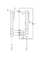
例えば、図7に示すように、従来の送受信システムQは、送信機B1と、受信機B2とを有し、該送信機B1は、PNコード発生部110と、搬送波発振器114と、増幅器118とを有し、受信機B2は、増幅器120と、PNコード捕捉同期部122と、PNコード発生部124と、復調部128とを有している。
【0004】
すなわち、情報信号は、まず、乗算器112でPNコード発生部110からのPNコードにより変調され、次に、乗算器116で搬送波発振器114からの搬送波により変調されて、増幅器118で増幅されて出力される。また、受信機B2においては、受信信号が増幅器120で増幅され、PNコード発生部124、PNコード捕捉同期部122により送信側のPNコードと同期したPNコードが乗算器126で乗算されて逆拡散が行われた後に、復調部128で通常のデータ復調が行われる。
【0005】
つまり、上記スペクトラム拡散通信においては、送信側において、PNコードを用いて送信信号を拡散変調して拡散コードとし、この拡散コードを受信側に送信し、受信側では、同じPNコードを用いて受信信号を逆拡散して送信信号を得る。
【0006】
ここで、拡散符号として使用されるPNコードの発生器としては、通常、M系列発生器が使用される。つまり、M系列のPNコードが使用される。このM系列の自己相関関数においては、M系列1周期に1つのピークが存在する。
【0007】
【発明が解決しようとする課題】
しかし、実際に使用されるPNコードとしては、上記M系列以外(非M系列)のPNコードを使用する場合がある。特に、多元接続を行う場合には、相互相関のなるべく低いPNコードを選択する必要があり、M系列以外のPNコードが選択される可能性が出てくる。この非M系列のPNコードでは、その自己相関特性において1周期に複数のピークを有することが知られている。
【0008】
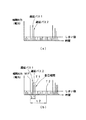
すると、受信信号の遅延プロファイルにおいては、図6(b)に示すように、出現するピークが遅延パスであるのか、自己相関結果であるのかが判別できず、結果として、自己相関結果を誤って有効パスと検出してしまうおそれがあった。
【0009】
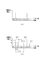
すなわち、例えば、M系列のPNコードの場合には、図5(a)に示すように、その自己相関特性は1周期において1つのピークを示し、このM系列のPNコードを用いて受信信号との相関を検出し、遅延プロファイルを測定すると、図6(a)に示すように、ダイレクトパスと遅延パスが検出される。一方、非M系列のPNコードの場合には、図5(b)に示すように、その自己相関特性は1周期において複数のピーク示し、その遅延プロファイルには、図6(b)に示すように、ダイレクトパスと遅延パスのみならず、自己相関のサブピークに基づくピークも検出されてしまい、この自己相関のサブピークに基づくピークが所定の選択範囲に入った場合には、これを有効パスと誤って検出してしまうことになる。
【0010】
そこで、本発明は、自己相関を有するPNコード、すなわち、非M系列のPNコードを用いた場合にも、適切に有効パスを検出することができる有効パス検出装置を提供することを目的とするものである。
【0011】
【課題を解決するための手段】
本発明は上記問題点を解決するために創作されたものであって、第1には、拡散符号によりスペクトラム拡散された信号である受信信号について有効パスを検出する有効パス検出装置であって、逆拡散符号を出力する逆拡散符号発生部と、該逆拡散符号発生部が出力する逆拡散符号の自己相関を検出する自己相関検出部と、該受信信号に基づき遅延プロファイルを生成する遅延プロファイル生成部と、該遅延プロファイル生成部により生成された遅延プロファイルと、上記自己相関検出部が検出した自己相関とに基づき、有効パスを検出する有効パス検出部と、を有し、上記自己相関検出部が、所定のレベルを越えるサブピークの時間情報と、該逆拡散符号の1周期におけるメインピークに対する該サブピークの割合の情報を出力し、上記有効パス検出部は、有効パスの検出に際して、該時間情報に対応するレベルから、遅延プロファイルにおけるダイレクトパスのレベルに上記割合を乗算した値を減算することにより遅延プロファイルの修正を行うことを特徴とする。この場合には、自己相関検出部が、上記時間情報とともに、該逆拡散符号の1周期におけるメインピークに対する該サブピークの割合の情報を出力し、さらに、上記有効パス検出部が、有効パスの検出に際して、該時間情報に対応する相関値から、遅延プロファイルにおけるダイレクトパスのレベルに上記割合を乗算した値を減算することにより遅延プロファイルの修正を行うので、自己相関におけるサブピークの影響を排除した遅延プロファイルを得ることにより適切な有効パスの検出を行うことができる。
【0018】
【発明の実施の形態】
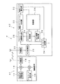
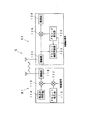
本発明の実施の形態としての実施例を図面を利用して説明する。本発明に基づく送受信システムPは、図1に示されるように、送信機A1と、受信機A2とを有している。ここで、送信機A1は、PNコード発生部10と、乗算器12と、搬送波発振器14と、乗算器16と、増幅器18とを有している。
【0019】
一方、受信機A2は、増幅器20と、AD変換部22と、PNコード発生部24と、PNコード相関検出部26と、自己相関検出部28と、遅延プロファイル生成部30と、有効パス検出部32と、RAKE合成部34と、制御部36とを有している。この受信機A2におけるPNコード発生部24、自己相関検出部28、遅延プロファイル生成部30、有効パス検出部32等は上記有効パス検出装置として機能する。
【0020】
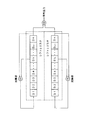
ここで、上記増幅器20は、アンテナを介して受信した受信信号の増幅を行い、AD変換部22は、A/D変換の処理を行う。また、上記逆拡散符号発生部としてのPNコード発生部24は、PNコード(逆拡散符号)を発生するPNコード発生器であり、例えば、図3、図4に示す例が挙げられる。この図3、図4に示す例は、非M系列のPNコードを発生するPNコード発生器である。また、PNコード相関検出部26は、受信信号とPNコードとの相関を検出するものである。このPNコード相関検出部26は、例えば、マッチドフィルタにより構成される。
【0021】
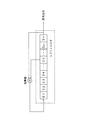
また、上記自己相関検出部28は、PNコード発生部24から出力されたPNコードの自己相関を検出するものであり、具体的には、図2に示すように、PNコードの各ビットデータを順次遅延させるためのシフトレジスタ50、52と、シフトレジスタ50、52内のビットデータをパラレルに乗算する複数の乗算器54と、該乗算器54で乗算された値を加算する加算器56とから構成されている。つまり、マッチドフィルタと同様の構成となっている。この各シフトレジスタ50、52には、ともにPNコードが入力されて自己相関を検出するようになっている。なお、上記シフトレジスタ50、52は、1周期分のPNコードを格納できるようになっている。
【0022】
また、上記遅延プロファイル生成部30は、PNコード相関検出部26において生成された相関値に基づき遅延プロファイルを生成する。遅延プロファイルは、横軸に遅延時間、縦軸に相関電力値を取り、この遅延プロファイルに表れるピークが各パスを介して到達した信号を表している。
【0023】
また、上記有効パス検出部32は、遅延プロファイルにおいて有効パスの検出を行う。つまり、所定のしきい値を越えているピーク値を検出するとともに、該ピーク値の遅延時間を有効パスのタイミング情報として検出する。なお、上記自己相関検出部28において、自己相関が検出されると、そのサブピークについての時間情報が該制御部36を介して有効パス検出部32に送られるので、該有効パス検出部32は、その時間情報に応じたピークを有効パスとはみなさない処理を行う。詳しくは後述する。
【0024】
また、上記RAKE合成部34は、上記有効パス検出部32により検出された有効パスについてのタイミング情報が有効パス検出部32から送られると、このタイミング情報に応じたタイミングで受信信号に対して逆拡散処理を行ってそのパス対応の復調信号を出力する。また、上記制御部36は、受信機A2における各部の動作を制御するものである。
【0025】
上記構成の送受信システムPの動作について説明する。まず、送信機A1の動作について説明する。情報信号は、まず、乗算器12でPNコード発生部10からのPNコードにより変調され、次に、乗算器16で搬送波発振器14からの搬送波により変調されて、増幅器18で増幅されてアンテナを介して出力される。
【0026】
一方、受信機A2においては、増幅器20において受信信号が増幅され、AD変換部22でA/D変換が行われる。そして、PNコード相関検出部26は、AD変換部22からの受信信号と、PNコード発生部24からのPNコードとの相関を検出する。また、遅延プロファイル生成部30は、PNコード相関検出部26において生成された相関値に従い遅延プロファイルを生成する。
【0027】
また、有効パス検出部32は、遅延プロファイルで生成された遅延プロファイルにおいて所定のしきい値以上の相関電力を有するピークを検出して有効パスを検出する。ここで、自己相関検出部28は、PNコード発生部24により発生するPNコードの自己相関を検出する。すなわち、図2に示すシフトレジスタ50にPNコードをセットするとともに、シフトレジスタ52にもPNコードをセットして、乗算器54で乗算した値を加算器56で加算し、その後、例えば、シフトレジスタ52内のデータを1ビットずつスライドさせていきながら、該加算処理を繰り返して自己相関を得る。この場合シフトレジスタ52内のPNコードは巡回するように構成される。つまり、シフトレジスタ52の右端のデータは次にはシフトレジスタ52の左端にくる。ここで、M系列のPNコードの場合には、図5(a)に示すように、PNコード1周期において1つのピークのみが表れ、一方、非M系列のPNコードの場合には、図5(b)に示すように、PNコード1周期において複数のピークが表れる。つまり、メインピークMPのみならず、サブピークSP1、SP2も表れる。このメインピークMP及びサブピークSP1、SP2はともにあるしきい値を越えるレベルのものである。すると、該自己相関検出部28は、このサブピークについての時間情報を制御部36を介して有効パス検出部32に送る。つまり、上記しきい値を越えるサブピークについての上記時間情報を有効パス検出部32に送る。この時間情報としては、例えば、メインピークからの時間差の情報とする。図5(b)の場合には、時間t1,時間t2の情報が送られる。
【0028】
この時間情報を受けた有効パス検出部32においては、その時間情報に対応する遅延時間のパスを有効パスからは除外して有効パスの検出を行う。例えば、図6(b)の例で、例えば、3つの有効パスを検出するものとした場合に、ダイレクトパスを示すメインピークから時間t1後の遅延時間T1のレベルが遅延パス2よりも大きな値を示す場合でも、この遅延時間T1のパスを有効パスとはみなさずに有効パスの検出を行う。同様に、メインピークから時間t2後の遅延時間T2のパスも有効パスとはみなさない。
【0029】
そして、有効パス検出部32は、この有効パスについての遅延時間の情報、すなわち、タイミング情報をRAKE合成部34に送り、該RAKE合成部34は、該タイミング情報に応じたタイミングで受信信号に対して逆拡散を行って該有効パス対応の復調信号を出力する。
【0030】
以上のように、本発明では、非M系列のPNコードを使用した場合でも、自己相関結果に基づくピークを誤って有効パスとして検出することがない。つまり、従来においては、図6(b)に示すような遅延プロファイルが得られた場合には、自己相関結果に基づくピークであるにも拘わらず、遅延時間T1のパスを有効パスとして検出してしまうが、本発明では、適切に有効パスを検出することができる。
【0031】
なお、上記の説明では、自己相関検出部28は、上記時間情報を出力するものとして説明したが、これには限られず、以下のようにしてもよい。
【0032】
つまり、自己相関検出部28は、上記時間情報とともに、レベル関連情報を有効パス検出部32に送る。ここで、該時間情報とは、上記と同様に、サブピーク、すなわち、所定のしきい値を越えるピークのうちメインピーク以外のものについてのメインピークとの時間差の情報である。また、該レベル関連情報とは、該サブピークのレベルのメインピークのレベルとの割合の情報である。例えば、図5(b)の例で、サブピークSP1については、上記時間情報は、時間t1の情報となり、上記レベル関連情報とは、該サブピークSP1のレベル(相関電力値)のメインピークMPのレベル(相関電力値)に対する割合の情報となる。つまり、図5(b)の例では、β/αとなる。すると、有効パス検出部32は、遅延プロファイル生成部30から送られた遅延プロファイルにおいて、その時間情報が示す位置のレベル(相関電力値)から、メインピークに該割合を乗算した値を減算して、遅延プロファイルを修正する。例えば、図6(b)の例では、図6(b)におけるメインピークMPの値をGとした場合に、遅延時間T1のレベルをG×β/α分減算する。つまり、自己相関結果を排除した形に遅延プロファイルを修正する。その上で、有効パスの検出を行うのである。有効パスの検出の方法は、従来と同様に、所定のしきい値を越えるピークの中から所定数のピークを有効パスとして選択する。この場合にも、上記と同様に、非M系列のPNコードを使用した場合でも、自己相関結果に基づくピークを誤って有効パスとして検出することがない。
【0033】
なお、上記時間情報とレベル関連情報とを制御部36を介して遅延プロファイル30に送り、該遅延プロファイル30がそれらの情報に基づいて遅延プロファイルを修正し、有効パス検出部32は従来通り有効パスを検出するようにしてもよい。
【0034】
【発明の効果】
本発明における有効パス検出装置によれば、非M系列のPNコードを拡散符号及び逆拡散符号に用いた場合にも、自己相関におけるサブピークに基づくピークのパスを誤って有効パスとして検出することがなく、適切に有効パスの検出を行うことができる。
【図面の簡単な説明】
【図1】本発明の実施例に基づく送受信システムの構成を示すブロック図である。
【図2】自己相関検出部の構成を示すブロック図である。
【図3】PNコード発生器の一例を示す回路図である。
【図4】PNコード発生器の他の一例を示す回路図である。
【図5】自己相関特性を示す説明図であり、(a)はM系列のPNコードの場合を示し、(b)は非M系列のPNコードの場合を示す説明図である。
【図6】遅延プロファイルの例を示す説明図であり、(a)は図5(a)の自己相関特性の場合の遅延プロファイルを示し、(b)は図5(b)の自己相関特性の場合の遅延プロファイルを示す説明図である。
【図7】スペクトラム拡散通信における送受信システムの従来例を示すブロック図である。
【符号の説明】
P 送受信システム
A1 送信機
A2 受信機
20 増幅器
22 AD変換部
24 PNコード発生部
26 PNコード相関検出部
28 自己相関検出部
30 遅延プロファイル生成部
32 有効パス検出部
34 RAKE合成部[0001]
BACKGROUND OF THE INVENTION
The present invention relates to a RAKE receiving apparatus in code division multiple access (CDMA) using direct spread spectrum, and more particularly to an apparatus for detecting an effective path.
[0002]
[Prior art]
A spread spectrum communication system is employed in a CDMA system or the like that is attracting attention as a recent telephone system. In this spread spectrum communication system, a PN code (pseudo-random code) is used as a spread code, the carrier wave of the transmission signal is spread and transmitted, and the pattern and phase of the code sequence of the spread code are made different so that multidimensional connection Is possible. Furthermore, this spread spectrum communication system employs a diversity RAKE combining method in order to reduce the influence of fading due to multipath. In this diversity RAKE combining method, the timing (delay time) of each delay path is detected from the delay profile obtained based on the received signal, and the received signal is demodulated (despread) based on the timing. According to the obtained data, the phase rotation amount of each spatial path is detected, and the signal component that has passed through each spatial path is extracted from the received signal based on the detected amount, and in-phase synthesis is performed.
[0003]
For example, as shown in FIG. 7, a conventional transmission / reception system Q includes a transmitter B1 and a receiver B2, which includes a PN
[0004]
That is, the information signal is first modulated by the multiplier 112 with the PN code from the PN
[0005]
In other words, in the above spread spectrum communication, on the transmitting side, the transmission signal is spread-modulated using the PN code to form a spreading code, and this spreading code is transmitted to the receiving side, and the receiving side receives using the same PN code. The signal is despread to obtain a transmission signal.
[0006]
Here, an M-sequence generator is usually used as a PN code generator used as a spreading code. That is, an M-sequence PN code is used. In this M-sequence autocorrelation function, one peak exists in one M-sequence period.
[0007]
[Problems to be solved by the invention]
However, as a PN code that is actually used, a PN code other than the M series (non-M series) may be used. In particular, when performing multiple access, it is necessary to select a PN code having a low cross-correlation as much as possible, and there is a possibility that a PN code other than the M sequence is selected. This non-M-sequence PN code is known to have a plurality of peaks in one cycle in its autocorrelation characteristics.
[0008]
Then, in the delay profile of the received signal, as shown in FIG. 6B, it cannot be determined whether the appearing peak is a delay path or an autocorrelation result, and as a result, the autocorrelation result is erroneously determined. There was a risk of detecting it as a valid path.
[0009]
That is, for example, in the case of an M-sequence PN code, as shown in FIG. 5A, the autocorrelation characteristic shows one peak in one cycle. As shown in FIG. 6A, a direct path and a delay path are detected. On the other hand, in the case of a non-M-sequence PN code, as shown in FIG. 5 (b), the autocorrelation characteristic shows a plurality of peaks in one cycle, and the delay profile shows as shown in FIG. 6 (b). In addition, not only the direct path and the delay path, but also peaks based on the autocorrelation subpeaks are detected. Will be detected.
[0010]
Accordingly, an object of the present invention is to provide an effective path detection device capable of appropriately detecting an effective path even when a PN code having autocorrelation, that is, a non-M sequence PN code is used. Is.
[0011]
[Means for Solving the Problems]
The present invention was created to solve the above problems, and firstly, an effective path detection device for detecting an effective path for a received signal that is a spectrum spread signal using a spreading code, A despread code generator that outputs a despread code, an autocorrelation detector that detects an autocorrelation of the despread code output from the despread code generator, and a delay profile generator that generates a delay profile based on the received signal And an effective path detection unit that detects an effective path based on the delay profile generated by the delay profile generation unit and the autocorrelation detected by the autocorrelation detection unit, and the autocorrelation detection unit Outputs sub-peak time information exceeding a predetermined level and information on the ratio of the sub-peak to the main peak in one cycle of the despread code. When detecting a valid path, the path detection unit corrects the delay profile by subtracting a value obtained by multiplying the direct path level in the delay profile by the ratio from the level corresponding to the time information. . In this case, the autocorrelation detection unit outputs information on the ratio of the sub-peak to the main peak in one cycle of the despread code together with the time information, and the effective path detection unit detects the effective path. At this time, since the delay profile is corrected by subtracting the value obtained by multiplying the direct path level in the delay profile by the above ratio from the correlation value corresponding to the time information, the delay profile in which the influence of the sub-peak in the autocorrelation is eliminated. Thus, it is possible to detect an appropriate effective path.
[0018]
DETAILED DESCRIPTION OF THE INVENTION
Embodiments of the present invention will be described with reference to the drawings. As shown in FIG. 1, the transmission / reception system P according to the present invention includes a transmitter A1 and a receiver A2. Here, the transmitter A1 includes a PN
[0019]
On the other hand, the receiver A2 includes an
[0020]
Here, the
[0021]
The
[0022]
The
[0023]
The
[0024]
Further, when timing information about the effective path detected by the effective
[0025]
The operation of the transmission / reception system P configured as described above will be described. First, the operation of the transmitter A1 will be described. The information signal is first modulated by the multiplier 12 with the PN code from the
[0026]
On the other hand, in the receiver A2, the received signal is amplified by the
[0027]
The effective
[0028]
Upon receiving this time information, the valid
[0029]
Then, the effective
[0030]
As described above, in the present invention, even when a non-M sequence PN code is used, a peak based on the autocorrelation result is not erroneously detected as an effective path. That is, in the related art, when a delay profile as shown in FIG. 6B is obtained, the path having the delay time T1 is detected as an effective path despite the peak based on the autocorrelation result. However, in the present invention, an effective path can be detected appropriately.
[0031]
In the above description, the
[0032]
That is, the
[0033]
The time information and the level related information are sent to the
[0034]
【The invention's effect】
According to the effective path detection apparatus of the present invention, even when a non-M sequence PN code is used for a spreading code and a despreading code, a peak path based on a sub-peak in autocorrelation can be erroneously detected as an effective path. Therefore, the effective path can be detected appropriately.
[Brief description of the drawings]
FIG. 1 is a block diagram showing a configuration of a transmission / reception system based on an embodiment of the present invention.
FIG. 2 is a block diagram showing a configuration of an autocorrelation detection unit.
FIG. 3 is a circuit diagram showing an example of a PN code generator.
FIG. 4 is a circuit diagram showing another example of a PN code generator.
FIGS. 5A and 5B are explanatory diagrams showing autocorrelation characteristics, in which FIG. 5A shows an M-sequence PN code and FIG. 5B shows a non-M-sequence PN code;
6A and 6B are explanatory diagrams showing examples of delay profiles, where FIG. 5A shows a delay profile in the case of the autocorrelation characteristics of FIG. 5A, and FIG. 6B shows the autocorrelation characteristics of FIG. It is explanatory drawing which shows the delay profile in a case.
FIG. 7 is a block diagram showing a conventional example of a transmission / reception system in spread spectrum communication.
[Explanation of symbols]
P transmission / reception system A1
Claims (1)
逆拡散符号を出力する逆拡散符号発生部と、
該逆拡散符号発生部が出力する逆拡散符号の自己相関を検出する自己相関検出部と、
該受信信号に基づき遅延プロファイルを生成する遅延プロファイル生成部と、
該遅延プロファイル生成部により生成された遅延プロファイルと、上記自己相関検出部が検出した自己相関とに基づき、有効パスを検出する有効パス検出部と、を有し、
上記自己相関検出部が、所定のレベルを越えるサブピークの時間情報と、該逆拡散符号の1周期におけるメインピークに対する該サブピークの割合の情報を出力し、上記有効パス検出部は、有効パスの検出に際して、該時間情報に対応するレベルから、遅延プロファイルにおけるダイレクトパスのレベルに上記割合を乗算した値を減算することにより遅延プロファイルの修正を行うことを特徴とする有効パス検出装置。An effective path detection device that detects an effective path for a received signal that is a spectrum spread signal by a spreading code,
A despread code generator for outputting a despread code;
An autocorrelation detector that detects the autocorrelation of the despread code output by the despread code generator;
A delay profile generator for generating a delay profile based on the received signal;
An effective path detection unit that detects an effective path based on the delay profile generated by the delay profile generation unit and the autocorrelation detected by the autocorrelation detection unit;
The autocorrelation detection unit outputs subpeak time information exceeding a predetermined level and information on the ratio of the subpeak to the main peak in one cycle of the despread code, and the effective path detection unit detects an effective path. In this case , the effective path detection apparatus corrects the delay profile by subtracting a value obtained by multiplying the level of the direct path in the delay profile by the ratio from the level corresponding to the time information .
Priority Applications (1)
| Application Number | Priority Date | Filing Date | Title |
|---|---|---|---|
| JP07668299A JP4100809B2 (en) | 1999-03-19 | 1999-03-19 | Effective path detection device |
Applications Claiming Priority (1)
| Application Number | Priority Date | Filing Date | Title |
|---|---|---|---|
| JP07668299A JP4100809B2 (en) | 1999-03-19 | 1999-03-19 | Effective path detection device |
Publications (2)
| Publication Number | Publication Date |
|---|---|
| JP2000278177A JP2000278177A (en) | 2000-10-06 |
| JP4100809B2 true JP4100809B2 (en) | 2008-06-11 |
Family
ID=13612218
Family Applications (1)
| Application Number | Title | Priority Date | Filing Date |
|---|---|---|---|
| JP07668299A Expired - Fee Related JP4100809B2 (en) | 1999-03-19 | 1999-03-19 | Effective path detection device |
Country Status (1)
| Country | Link |
|---|---|
| JP (1) | JP4100809B2 (en) |
Families Citing this family (6)
| Publication number | Priority date | Publication date | Assignee | Title |
|---|---|---|---|---|
| JP3468189B2 (en) | 2000-02-02 | 2003-11-17 | 日本電気株式会社 | Pattern generation circuit, multipath detection circuit using the same, and multipath detection method thereof |
| JP3510589B2 (en) | 2000-12-15 | 2004-03-29 | Necエレクトロニクス株式会社 | Cell search method and cell search device |
| JP3479845B2 (en) * | 2001-11-21 | 2003-12-15 | 日本電気株式会社 | CDMA receiver, base station thereof, and method of detecting reception timing for despreading the received signal |
| WO2004025861A1 (en) * | 2002-09-13 | 2004-03-25 | Mitsubishi Denki Kabushiki Kaisha | Rake RECEIVER |
| JP3590043B2 (en) * | 2003-01-15 | 2004-11-17 | 松下電器産業株式会社 | Synchronization acquisition device and synchronization acquisition method |
| JP2005151260A (en) * | 2003-11-17 | 2005-06-09 | Matsushita Electric Ind Co Ltd | Apparatus and method for capturing synchronization |
-
1999
- 1999-03-19 JP JP07668299A patent/JP4100809B2/en not_active Expired - Fee Related
Also Published As
| Publication number | Publication date |
|---|---|
| JP2000278177A (en) | 2000-10-06 |
Similar Documents
| Publication | Publication Date | Title |
|---|---|---|
| US6141374A (en) | Method and apparatus for generating multiple matched-filter PN vectors in a CDMA demodulator | |
| US5724384A (en) | PN code sync device using an adaptive threshold | |
| US5909435A (en) | Wideband code-division multiple access system and method | |
| US5974038A (en) | Receiver for code division multiple access communication system | |
| US7167456B2 (en) | Apparatus for estimating propagation path characteristics | |
| JP3454569B2 (en) | Synchronization method for code division multiple access wireless communication | |
| JP5002838B2 (en) | Combination of subchip resolution samples in the arms of a spread spectrum rake receiver. | |
| EP0748074B1 (en) | Spread spectrum transmitter and receiver employing composite spreading codes | |
| USRE38523E1 (en) | Spreading code sequence acquisition system and method that allows fast acquisition in code division multiple access (CDMA) systems | |
| KR100552076B1 (en) | Signal receiving device in CDMA communication system | |
| JP2780697B2 (en) | Method and apparatus for acquiring synchronization in correlation demodulation | |
| AU702556B2 (en) | Receiver, and method for generating spreading codes in a receiver | |
| US6882682B1 (en) | Fixed pattern detection apparatus | |
| KR970705258A (en) | A code division multiple access (CDMA) demodulation device (CDMA DEMODULATING APPARATUS) | |
| JPH09181704A (en) | Cdma multi-path searth method and cdma signal receiver | |
| JP3385200B2 (en) | Signal transmission method and spreading code synchronization method in mobile communication system | |
| JP2000307470A (en) | Receiver device | |
| JP4100809B2 (en) | Effective path detection device | |
| KR100355376B1 (en) | Apparatus for acquisition for asynchronous wideband DS/CDMA signal | |
| JP2973416B1 (en) | RAKE receiving circuit | |
| JP3418981B2 (en) | Spread spectrum communication synchronization acquisition circuit | |
| JP5634354B2 (en) | Communication system and receiver | |
| JP2797921B2 (en) | Spreading code generation method | |
| JP2000224076A (en) | Receiver | |
| JP2003198500A (en) | System and method for spread spectrum communication |
Legal Events
| Date | Code | Title | Description |
|---|---|---|---|
| A621 | Written request for application examination |
Free format text: JAPANESE INTERMEDIATE CODE: A621 Effective date: 20050915 |
|
| A977 | Report on retrieval |
Free format text: JAPANESE INTERMEDIATE CODE: A971007 Effective date: 20071130 |
|
| A131 | Notification of reasons for refusal |
Free format text: JAPANESE INTERMEDIATE CODE: A131 Effective date: 20071211 |
|
| A521 | Written amendment |
Free format text: JAPANESE INTERMEDIATE CODE: A523 Effective date: 20080124 |
|
| TRDD | Decision of grant or rejection written | ||
| A01 | Written decision to grant a patent or to grant a registration (utility model) |
Free format text: JAPANESE INTERMEDIATE CODE: A01 Effective date: 20080219 |
|
| A61 | First payment of annual fees (during grant procedure) |
Free format text: JAPANESE INTERMEDIATE CODE: A61 Effective date: 20080318 |
|
| FPAY | Renewal fee payment (event date is renewal date of database) |
Free format text: PAYMENT UNTIL: 20110328 Year of fee payment: 3 |
|
| FPAY | Renewal fee payment (event date is renewal date of database) |
Free format text: PAYMENT UNTIL: 20110328 Year of fee payment: 3 |
|
| FPAY | Renewal fee payment (event date is renewal date of database) |
Free format text: PAYMENT UNTIL: 20130328 Year of fee payment: 5 |
|
| FPAY | Renewal fee payment (event date is renewal date of database) |
Free format text: PAYMENT UNTIL: 20140328 Year of fee payment: 6 |
|
| S111 | Request for change of ownership or part of ownership |
Free format text: JAPANESE INTERMEDIATE CODE: R313113 |
|
| R350 | Written notification of registration of transfer |
Free format text: JAPANESE INTERMEDIATE CODE: R350 |
|
| LAPS | Cancellation because of no payment of annual fees |