JP4100106B2 - Vehicle steering control device - Google Patents
Vehicle steering control device Download PDFInfo
- Publication number
- JP4100106B2 JP4100106B2 JP2002263946A JP2002263946A JP4100106B2 JP 4100106 B2 JP4100106 B2 JP 4100106B2 JP 2002263946 A JP2002263946 A JP 2002263946A JP 2002263946 A JP2002263946 A JP 2002263946A JP 4100106 B2 JP4100106 B2 JP 4100106B2
- Authority
- JP
- Japan
- Prior art keywords
- steering
- command value
- electric motor
- electric motors
- driving force
- Prior art date
- Legal status (The legal status is an assumption and is not a legal conclusion. Google has not performed a legal analysis and makes no representation as to the accuracy of the status listed.)
- Expired - Fee Related
Links
Images

Landscapes
- Power Steering Mechanism (AREA)
- Control Of Multiple Motors (AREA)
- Steering Control In Accordance With Driving Conditions (AREA)
Description
【0001】
【発明の属する技術分野】
本発明は、ステアリング操作に応じて操向車輪を転舵する車両用操舵制御装置に関するものである。
【0002】
【従来の技術】
従来、この種の車両用操舵制御装置として、例えば、舵取機構と機械的に連結されていないステアリングホイールを備える構成において、舵取機構の相異なる位置に主操舵モータと副操舵モータとを配設し、舵取制御部は、操舵角センサにより検出されるステアリングホイールの操作状態と、タイロッド変位センサにより検出される舵取機構の実動作位置とに基づいて必要操舵力を求め、これを予め設定された比率で配分して主操舵モータ及び副操舵モータの出力が目標値となるように両操舵モータを駆動制御して、これらの出力の合力を舵取機構に加えて舵取を行わせるように構成された自動車の舵取装置がある(特許文献1参照)。
【0003】
【特許文献1】
特開平10−218000号公報
【0004】
【発明が解決しようとする課題】
しかしながら、上記従来例にあっては、主操舵モータと副操舵モータに対する必要操舵力の配分率が一定に定まっているので、例えば、主操舵モータ、又は副操舵モータの何れかの抵抗値が、温度の上昇によって増加すると、そのモータの熱ストレスが増加することにより耐久性能が低下してしまうという未解決の課題がある。
【0005】
そこで、本発明は上記従来例の未解決の課題に着目してなされたものであり、操向車輪に連結された転舵軸に転舵力を付与する複数の電動モータの熱ストレスを軽減して、耐久性能を向上させた車両用操舵制御装置を提供することを目的としている。
【0006】
【課題を解決するための手段】
上記目的を達成するために、本発明に係る車両用操舵制御装置は、ステアリング操作状態に応じて、操向車輪に連結された転舵軸に転舵力を付与する複数の電動モータに対する総駆動力指令値を算出し、配分手段が、算出された総駆動力指令値の各電動モータに対する配分率を、各電動モータの抵抗値の比率に基づいて設定することを特徴としている。
【0007】
【発明の効果】
本発明に係る車両用操舵制御装置によれば、ステアリング操作状態に応じて、操向車輪に連結された転舵軸に転舵力を付与する複数の電動モータに対する総駆動力指令値を算出し、算出された総駆動力指令値の各電動モータに対する配分率を、各電動モータ同士の抵抗値の比率に基づいて決定するように構成されているので、各電動モータに生じる熱ストレスを軽減して、耐久性能を向上させることができるという効果が得られる。
【0008】
【発明の実施の形態】
以下、本発明の実施形態を図面に基づいて説明する。
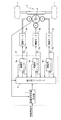
図1は本発明を、ステアリング操作される操舵側と操向車輪に連結された転舵側とを機械的に分離させた所謂ステアリング・バイ・ワイヤ方式の車両用操舵制御装置に適用した場合の一実施形態を示す概略構成図である。
【0009】
図中、1は転舵軸2に連結した操向車輪であり、3i(以下、i=a、b、cとする)はステアリング操作状態に応じた転舵力を転舵軸2に付与する同一型の電動モータである。これら各電動モータ3iに対して要求されるトルク配分は、1:1:1となるように予め設定されている。転舵軸2の転舵角は、例えばロータリエンコーダで構成された角度センサ4により検出され、また、各電動モータ3iに入力される電流値Iiは、電流センサ5iにより検出されている。そして、各電動モータ3iは、制御装置6によって回転トルク、及び回転方向が駆動制御される。
【0010】
制御装置6は、ステアリング操作状態に応じた操向車輪の転舵角指令、及び角度センサ4で検出される転舵角に基づいて総駆動力指令値としての総電流指令値Itotalを算出する総電流指令値算出器7と、総電流指令値算出器7で算出された総電流指令値Itotalを、各電動モータ3iに対する電流指令値Iiとに配分する配分手段としての配分用コントローラ8と、配分用コントローラ8で配分された電流指令値Iiに基づいて、各電動モータ3iを駆動すると共に、電動モータ3iの夫々の電機子電圧Eiを検出して配分用コントローラ8に出力する駆動用コントローラ9iとで構成されている。
【0011】
配分用コントローラ8は、例えば、例えば、マイクロコンピュータで構成され、角度センサ3、電流センサ5i、及び駆動用コントローラ9iで検出される各種信号に基づいて、図2の総電流指令値配分処理を常時実行し、総電流指令値Itotalを各電動モータ3iに対する電流指令値Iiに配分して、駆動用コントローラ9iに夫々出力する。
【0012】
次に、配分用コントローラ8で実行する総電流指令値配分処理を、図2のフローチャートに従って説明する。
この配分処理は、先ず、ステップS1で、各電動モータ3iの抵抗値Riを算出する。電動モータのコイル抵抗値をR、電流値をI、電動モータの回転速度をV、電動モータの電機子電圧をE、電動モータの逆起電力係数をkとすると、下記(1)式の関係が成り立ち、この(1)式を下記(2)式のように変形させて、抵抗値Rを算出することができる。
【0013】
E=R・I+k・V ・・・・・・(1)
R=(E−k・V)/I ・・・・・・(2)
したがって、回転速度Vは角度センサ3から出力されるパルス信号の周期に基づいて算出したもの、電流値Iiは電流センサ5i、また電機子電圧Eiは駆動用コントローラ9iで検出したものを、夫々読込んで、前記(2)式に従って、各電動モータ3iの抵抗値Riを算出してから、ステップS2に移行する。
【0014】
ステップS2では、総電流指令値算出器7で算出された、総電流指令値Itotalを読込んでから、ステップS3に移行する。
ステップS3では、ステップS2で読込んだ総電流指令値Itotalを、前記ステップS1で算出した抵抗値Riに応じて、各電動モータ3iへ配分する電流指令値Iiを算出する。先ず、電動モータの消費電力をPとすると、下記(3)式に従って算出することができる。
【0015】
P=I2・R ・・・・・・(3)
そして、各電動モータ3iに対して要求されるトルク配分は予め設定された1:1:1であるため、電流値Ia、Ib及びIcにおける設計上の関係は、Ia=Ib=Icとなる。これら電流値Iiと総電流指令値Itotalとは、下記(4)式に示す関係にある。
【0016】
Itotal=Ia+Ib+Ic ・・・・・・(4)
また、各電動モータ3iは同一型であるため、各抵抗値Ra、Rb及びRcにおける設計上の関係は、Ra=Rb=Rcとなる。したがって、前記(3)に基づいて各消費電力を算出するときに、下記(5)式を導くことができる。
Ia2・Ra=Ib2・Rb=Ic2・Rc ・・・・・・(5)
また、上記(5)式に基づき、Ib、及びIcは、下記(6)式、及び(7)式に従って算出することができる。
【0017】
【数1】

【数2】
そして、上記(6)式、及び(7)式を、前記(4)式に代入することにより、下記(8)式を導き、更にこの(8)式を変形することにより、Iaを求める下記(9)式を導き出すことができる。
【0020】
【数3】
【数4】
同様に、上記(4)式、及び(5)式に基づいて、Ib、及びIcを求める下記(10)式、及び(11)式を導き出すことができる。
【0023】
【数5】
【数6】
したがって、前記ステップS1で算出された各電動モータ3iの抵抗値Riと、前記ステップS2で読込まれた総電流指令値Itotalとを、前記(9)式、(10)式、及び(11)式に代入することにより、電動モータ3iに対する電流指令値Iiを算出し、ステップS4に移行する。そして、このステップS4で算出された電流指令値Iiを、夫々、各駆動用コントローラ9iに出力してから前記ステップS1に戻る。
【0026】
ここで、ステップS1の処理が抵抗値算出手段に対応し、ステップS3の処理が配分手段に対応している。
次に、上記実施形態の動作を説明する。
今、運転者がステアリング操作を開始すると、先ず、このステアリング操作に応じて操向車輪1を転舵する角度指令値が総電流指令値算出器7に入力され、この総電流指令値算出器7が、角度指令値応じて電動モータ3aiを駆動するのに必要な総電流指令値Itotalを算出し、配分用コントローラ8へ出力する。
【0027】
そして、配分用コントローラ8は、総電流指令値Itotalを、電流指令値Iiに配分して(ステップS3)、各駆動用コントローラ9iに出力することにより(ステップS4)、電流指令値Iiに基づいて各電動モータ3iが駆動される。このとき、各電動モータ3iの温度が上昇しておらず、その抵抗値Riが予め設定された1:1:1の比率を維持しているときには、前記(9)式、(10)式、及び(11)式に基づいて算出される各電流指令値Iiも、1:1:1の比率となるので、各電動モータ3iが同量のトルクを転舵軸2に付与する。
【0028】
ところが、同一型の電動モータを使用しているときでも、初期抵抗値のバラツキのみならず、例えば、排気等の熱源に近い位置に配設された電動モータは他の電動モータに比べて加熱しやすいため、抵抗値が増加し、夫々の抵抗値Riの比率が変動し得る。この抵抗値の増加に伴う熱ストレスは、電動モータの耐久性能の低下を招来するため、抵抗値が所定の値から増加した電動モータにはトルク配分を軽減させ、この減少分を残りの電動モータで補えば、抵抗値が増加した電動モータの熱ストレスを軽減することができる。なお、所定の値とは、他の電動モータの抵抗値との比率により設定される。
【0029】
したがって、例えば、電動モータ3aの抵抗値Raが、他の電動モータ3b及び3cの抵抗値Rb及びRcに比べて大きくなったとすると、電動モータ3aに対する電流指令値Iaは前記(9)式に従って、Ib及びIcに比べて相対的に減少するように算出される。一方、電動モータ3b及び3cの抵抗値Rb及びRcは、Raに比べて小さくなるので、電動モータ3b及び3cに対する電流指令値Ib及びIcは、前記(10)式、及び(11)式に従って、Iaに比べて相対的に増加するように算出される。
【0030】
このように、抵抗値が増加した電動モータには、電流指令値の配分率を減少させると共に、他の電動モータには、電流指令値の配分率を増加させることにより、各電動モータ3iの熱ストレスを可及的に軽減して、その耐久性能を向上させることができる。
なお、上記実施形態では、トルク配分が均等となるように同一型の電動モータを複数備えた構成について説明したが、これに限定されるものではなく、定格出力の異なる複数の電動モータを使用して、予め設定するトルク配分を換えてもよい。
【0031】
さらに、上記実施形態では、本発明を、ステアリング操作される操舵側と操向車輪に連結された転舵側とを機械的に分離させた所謂ステアリング・バイ・ワイヤ方式に適用した場合について説明したが、これに限定されるものではない。すなわち、例えば、操舵側と転舵側とが機械的に結合されており、その転舵側に、補助転舵力を付与する複数の電動モータを備えた構成にも、本発明を適用することができる。
【0032】
以上のように、上記実施形態によれば、配分用コントローラ8は、各電動モータの抵抗値の比率が、予め設定された所定比率から変動するとき、通常時の抵抗値より値が増加した電動モータに対する総駆動力指令値の配分率を減少させるように構成されているので、各電動モータに生じる熱ストレスを確実に軽減して、耐久性能を向上させることができるという効果が得られる。
【0033】
また、上記実施形態によれば、複数の電動モータが、ステアリング操作される操舵側と操向車輪に連結された転舵側とが機械的に分離した構造の当該転舵側に配設されているので、操舵側と転舵側とを連結した構造に比べれば、電動モータにおけるレイアウトの自由度が比較的低いが、排気等の熱源に近い場所にも電動モータを配設することができ、レイアウトの自由度を改善することができるという効果が得られる。
【図面の簡単な説明】
【図1】本発明の概略構成図である。
【図2】駆動指令値配分処理の一例を示すフローチャートである。
【符号の説明】
1 操向車輪
2 転舵軸
3a、3b、3c 電動モータ
4 角度センサ
5a、5b、5c 電流センサ
6 制御装置
7 電流指令値算出器(駆動力指令値算出手段)
8 配分用コントローラ(配分手段)
9 駆動用コントローラ[0001]
BACKGROUND OF THE INVENTION
The present invention relates to a vehicle steering control device that steers steering wheels in response to a steering operation.
[0002]
[Prior art]
Conventionally, as a steering control device for a vehicle of this type, for example, in a configuration including a steering wheel that is not mechanically connected to a steering mechanism, a main steering motor and a sub steering motor are arranged at different positions of the steering mechanism. The steering control unit obtains a necessary steering force based on the operation state of the steering wheel detected by the steering angle sensor and the actual operation position of the steering mechanism detected by the tie rod displacement sensor. Both the steering motors are driven and controlled so that the outputs of the main steering motor and the auxiliary steering motor become target values by distributing at a set ratio, and the resultant force of these outputs is applied to the steering mechanism to perform steering. There is a steering apparatus for an automobile configured as described above (see Patent Document 1).
[0003]
[Patent Document 1]
Japanese Patent Laid-Open No. 10-218000
[Problems to be solved by the invention]
However, in the conventional example, since the distribution ratio of the necessary steering force to the main steering motor and the sub steering motor is fixed, for example, the resistance value of either the main steering motor or the sub steering motor is When the temperature increases, there is an unsolved problem that the durability performance deteriorates due to an increase in thermal stress of the motor.
[0005]
Therefore, the present invention has been made paying attention to the unsolved problems of the above-described conventional example, and reduces the thermal stress of a plurality of electric motors that impart a turning force to the turning shaft connected to the steered wheels. An object of the present invention is to provide a vehicle steering control device with improved durability performance.
[0006]
[Means for Solving the Problems]
In order to achieve the above object, a vehicle steering control device according to the present invention provides a total drive for a plurality of electric motors that apply a turning force to a turning shaft connected to a steered wheel according to a steering operation state. The force command value is calculated, and the distribution means sets the distribution ratio of the calculated total driving force command value to each electric motor based on the ratio of the resistance values of each electric motor.
[0007]
【The invention's effect】
According to the vehicle steering control device of the present invention, a total driving force command value for a plurality of electric motors for applying a turning force to a turning shaft connected to a steered wheel is calculated according to a steering operation state. Since the distribution ratio of the calculated total driving force command value to each electric motor is determined based on the ratio of the resistance values between the electric motors, the thermal stress generated in each electric motor is reduced. Thus, the effect that the durability performance can be improved is obtained.
[0008]
DETAILED DESCRIPTION OF THE INVENTION
Hereinafter, embodiments of the present invention will be described with reference to the drawings.
FIG. 1 shows a case where the present invention is applied to a so-called steering-by-wire vehicle steering control device in which a steering side to be steered and a steered side connected to a steering wheel are mechanically separated. It is a schematic structure figure showing one embodiment.
[0009]
In the figure, 1 is a steered wheel connected to the steered
[0010]
The control device 6 calculates the total current command value Itotal as the total driving force command value based on the steering angle command of the steered wheels according to the steering operation state and the steering angle detected by the angle sensor 4. A current
[0011]
The
[0012]
Next, the total current command value distribution process executed by the
In this distribution process, first, in step S1, the resistance value Ri of each electric motor 3i is calculated. When the coil resistance value of the electric motor is R, the current value is I, the rotation speed of the electric motor is V, the armature voltage of the electric motor is E, and the counter electromotive force coefficient of the electric motor is k, the relationship of the following equation (1) Therefore, the resistance value R can be calculated by transforming the equation (1) into the following equation (2).
[0013]
E = R · I + k · V (1)
R = (E−k · V) / I (2)
Therefore, the rotation speed V is calculated based on the period of the pulse signal output from the angle sensor 3, the current value Ii is read by the current sensor 5i, and the armature voltage Ei is read by the drive controller 9i. In accordance with the equation (2), the resistance value Ri of each electric motor 3i is calculated, and then the process proceeds to step S2.
[0014]
In step S2, the total current command value Itotal calculated by the total current
In step S3, a current command value Ii to be distributed to each electric motor 3i is calculated according to the resistance value Ri calculated in step S1 with respect to the total current command value Itotal read in step S2. First, when the power consumption of the electric motor is P, it can be calculated according to the following equation (3).
[0015]
P = I 2 · R (3)
Since the torque distribution required for each electric motor 3i is 1: 1: 1 set in advance, the design relationship among the current values Ia, Ib and Ic is Ia = Ib = Ic. The current value Ii and the total current command value Itotal have a relationship represented by the following equation (4).
[0016]
Itotal = Ia + Ib + Ic (4)
Moreover, since each electric motor 3i is the same type, the design relationship among the resistance values Ra, Rb, and Rc is Ra = Rb = Rc. Therefore, when calculating each power consumption based on (3), the following equation (5) can be derived.
Ia 2 · Ra = Ib 2 · Rb = Ic 2 · Rc (5)
Further, based on the above equation (5), Ib and Ic can be calculated according to the following equations (6) and (7).
[0017]
[Expression 1]
[Expression 2]
Then, by substituting the above equations (6) and (7) into the above equation (4), the following equation (8) is derived, and further, this equation (8) is modified to obtain Ia: Equation (9) can be derived.
[0020]
[Equation 3]
[Expression 4]
Similarly, the following formulas (10) and (11) for obtaining Ib and Ic can be derived based on the above formulas (4) and (5).
[0023]
[Equation 5]
[Formula 6]
Therefore, the resistance value Ri of each electric motor 3i calculated in step S1 and the total current command value Itotal read in step S2 are expressed by the above equations (9), (10), and (11). By substituting into, current command value Ii for electric motor 3i is calculated, and the process proceeds to step S4. Then, the current command value Ii calculated in step S4 is output to each drive controller 9i, and then the process returns to step S1.
[0026]
Here, the process of step S1 corresponds to the resistance value calculation means, and the process of step S3 corresponds to the distribution means.
Next, the operation of the above embodiment will be described.
Now, when the driver starts the steering operation, first, an angle command value for turning the steered
[0027]
Then, the
[0028]
However, even when the same type of electric motor is used, not only the variation in initial resistance value, but also, for example, an electric motor disposed near a heat source such as exhaust heats up compared to other electric motors. Since it is easy, resistance value increases and the ratio of each resistance value Ri may fluctuate. The thermal stress accompanying the increase in the resistance value causes a decrease in the durability performance of the electric motor. Therefore, the torque distribution is reduced for the electric motor whose resistance value has increased from a predetermined value, and this decrease is used for the remaining electric motors. If it supplements with, it can reduce the thermal stress of the electric motor whose resistance value increased. The predetermined value is set by a ratio with the resistance value of another electric motor.
[0029]
Therefore, for example, if the resistance value Ra of the
[0030]
As described above, the electric motors having increased resistance values decrease the current command value distribution rate, while other electric motors increase the current command value distribution rate, thereby increasing the heat of each electric motor 3i. Stress can be reduced as much as possible, and its durability can be improved.
In the above-described embodiment, the configuration in which a plurality of electric motors of the same type are provided so that the torque distribution is uniform has been described. However, the present invention is not limited to this, and a plurality of electric motors having different rated outputs are used. Thus, the preset torque distribution may be changed.
[0031]
Further, in the above embodiment, the case where the present invention is applied to a so-called steering-by-wire system in which the steering side operated by steering and the steered side connected to the steered wheels are mechanically separated has been described. However, the present invention is not limited to this. That is, for example, the present invention is applied to a configuration in which the steering side and the steered side are mechanically coupled, and the steered side includes a plurality of electric motors that provide auxiliary steering force. Can do.
[0032]
As described above, according to the above-described embodiment, the
[0033]
Further, according to the above embodiment, the plurality of electric motors are disposed on the steering side of the structure in which the steering side operated by steering and the steering side connected to the steered wheels are mechanically separated. Therefore, compared to a structure in which the steering side and the steered side are connected, the degree of freedom of layout in the electric motor is relatively low, but the electric motor can be arranged in a place close to a heat source such as exhaust, The effect that the freedom degree of layout can be improved is acquired.
[Brief description of the drawings]
FIG. 1 is a schematic configuration diagram of the present invention.
FIG. 2 is a flowchart illustrating an example of a drive command value distribution process.
[Explanation of symbols]
DESCRIPTION OF
8 Controller for distribution (distribution means)
9 Drive controller
Claims (3)
前記複数の電動モータごとに抵抗値を算出する抵抗値算出手段を有し、前記配分手段は、前記抵抗値算出手段で算出された各電動モータの抵抗値の比率に基づいて、前記総駆動力指令値の配分率を設定することを特徴とする車両用操舵制御装置。Calculation of a total driving force command value for calculating a plurality of electric motors for applying a steering force to the steering shaft connected to the steering wheel and a total driving force command value for the plurality of electric motors according to a steering operation state A vehicle steering control device comprising: a means for distributing the total driving force command value calculated by the total driving force command value calculating means to the electric motors;
A resistance value calculating unit configured to calculate a resistance value for each of the plurality of electric motors, and the distributing unit is configured to calculate the total driving force based on a ratio of resistance values of the electric motors calculated by the resistance value calculating unit. A steering control device for a vehicle, wherein a distribution ratio of command values is set.
Priority Applications (1)
| Application Number | Priority Date | Filing Date | Title |
|---|---|---|---|
| JP2002263946A JP4100106B2 (en) | 2002-09-10 | 2002-09-10 | Vehicle steering control device |
Applications Claiming Priority (1)
| Application Number | Priority Date | Filing Date | Title |
|---|---|---|---|
| JP2002263946A JP4100106B2 (en) | 2002-09-10 | 2002-09-10 | Vehicle steering control device |
Publications (2)
| Publication Number | Publication Date |
|---|---|
| JP2004098872A JP2004098872A (en) | 2004-04-02 |
| JP4100106B2 true JP4100106B2 (en) | 2008-06-11 |
Family
ID=32263516
Family Applications (1)
| Application Number | Title | Priority Date | Filing Date |
|---|---|---|---|
| JP2002263946A Expired - Fee Related JP4100106B2 (en) | 2002-09-10 | 2002-09-10 | Vehicle steering control device |
Country Status (1)
| Country | Link |
|---|---|
| JP (1) | JP4100106B2 (en) |
Cited By (1)
| Publication number | Priority date | Publication date | Assignee | Title |
|---|---|---|---|---|
| JPH06156632A (en) * | 1992-11-27 | 1994-06-03 | Murata Mach Ltd | Elevating base for crane |
Families Citing this family (3)
| Publication number | Priority date | Publication date | Assignee | Title |
|---|---|---|---|---|
| JP4609086B2 (en) * | 2005-01-27 | 2011-01-12 | 株式会社ジェイテクト | Vehicle steering system |
| EP2216234B1 (en) | 2007-11-19 | 2016-04-13 | Toyota Jidosha Kabushiki Kaisha | Vehicle steering control device |
| JP4989441B2 (en) * | 2007-12-19 | 2012-08-01 | 株式会社東海理化電機製作所 | Webbing retractor and motor actuator |
-
2002
- 2002-09-10 JP JP2002263946A patent/JP4100106B2/en not_active Expired - Fee Related
Cited By (1)
| Publication number | Priority date | Publication date | Assignee | Title |
|---|---|---|---|---|
| JPH06156632A (en) * | 1992-11-27 | 1994-06-03 | Murata Mach Ltd | Elevating base for crane |
Also Published As
| Publication number | Publication date |
|---|---|
| JP2004098872A (en) | 2004-04-02 |
Similar Documents
| Publication | Publication Date | Title |
|---|---|---|
| US20050205344A1 (en) | Electrically driven power steering system for vehicle | |
| JP4941723B2 (en) | Vehicle steering system | |
| TW200307617A (en) | Vehicle steering control apparatus | |
| JP3611116B2 (en) | Electric power steering control device | |
| JP6252027B2 (en) | Steering control device | |
| EP1419952A2 (en) | Electric steering control device | |
| JP6299087B2 (en) | Steering control device | |
| EP1518776B1 (en) | Control apparatus for an electrically driven power steering | |
| JP4100106B2 (en) | Vehicle steering control device | |
| US6734649B1 (en) | Dynamic tuning of current loop controller for a permanent magnet brushless motor | |
| Kurishige et al. | Static steering-control system for electric-power steering | |
| EP2574523B1 (en) | Vehicle steering system | |
| JP3755273B2 (en) | Steering control device | |
| JP4788856B2 (en) | Vehicle steering device | |
| JP2004034923A (en) | Steering control | |
| JP6252059B2 (en) | Steering control device | |
| JP3780141B2 (en) | Electric power steering control device | |
| JP3865631B2 (en) | Electric power steering device | |
| JP2009166715A (en) | Electric power steering device | |
| JP3865529B2 (en) | Electric power steering device | |
| JP3555126B2 (en) | Steering control device | |
| JP4586258B2 (en) | Vehicle steering control device | |
| JP5045872B2 (en) | Electric power steering device | |
| JPH10218001A (en) | Steering device for vehicle | |
| US20240051595A1 (en) | Dual motor drive assembly |
Legal Events
| Date | Code | Title | Description |
|---|---|---|---|
| A621 | Written request for application examination |
Free format text: JAPANESE INTERMEDIATE CODE: A621 Effective date: 20050624 |
|
| A977 | Report on retrieval |
Free format text: JAPANESE INTERMEDIATE CODE: A971007 Effective date: 20080219 |
|
| TRDD | Decision of grant or rejection written | ||
| A01 | Written decision to grant a patent or to grant a registration (utility model) |
Free format text: JAPANESE INTERMEDIATE CODE: A01 Effective date: 20080226 |
|
| A61 | First payment of annual fees (during grant procedure) |
Free format text: JAPANESE INTERMEDIATE CODE: A61 Effective date: 20080310 |
|
| FPAY | Renewal fee payment (event date is renewal date of database) |
Free format text: PAYMENT UNTIL: 20110328 Year of fee payment: 3 |
|
| R150 | Certificate of patent or registration of utility model |
Free format text: JAPANESE INTERMEDIATE CODE: R150 |
|
| FPAY | Renewal fee payment (event date is renewal date of database) |
Free format text: PAYMENT UNTIL: 20110328 Year of fee payment: 3 |
|
| FPAY | Renewal fee payment (event date is renewal date of database) |
Free format text: PAYMENT UNTIL: 20120328 Year of fee payment: 4 |
|
| FPAY | Renewal fee payment (event date is renewal date of database) |
Free format text: PAYMENT UNTIL: 20130328 Year of fee payment: 5 |
|
| FPAY | Renewal fee payment (event date is renewal date of database) |
Free format text: PAYMENT UNTIL: 20130328 Year of fee payment: 5 |
|
| LAPS | Cancellation because of no payment of annual fees |