JP4097873B2 - Image compression method and image compression apparatus for multispectral image - Google Patents
Image compression method and image compression apparatus for multispectral image Download PDFInfo
- Publication number
- JP4097873B2 JP4097873B2 JP2000060470A JP2000060470A JP4097873B2 JP 4097873 B2 JP4097873 B2 JP 4097873B2 JP 2000060470 A JP2000060470 A JP 2000060470A JP 2000060470 A JP2000060470 A JP 2000060470A JP 4097873 B2 JP4097873 B2 JP 4097873B2
- Authority
- JP
- Japan
- Prior art keywords
- image
- principal component
- tile
- multispectral
- optimum
- Prior art date
- Legal status (The legal status is an assumption and is not a legal conclusion. Google has not performed a legal analysis and makes no representation as to the accuracy of the status listed.)
- Expired - Fee Related
Links
Images


Classifications
-
- G—PHYSICS
- G06—COMPUTING; CALCULATING OR COUNTING
- G06T—IMAGE DATA PROCESSING OR GENERATION, IN GENERAL
- G06T9/00—Image coding
- G06T9/007—Transform coding, e.g. discrete cosine transform
Landscapes
- Physics & Mathematics (AREA)
- General Physics & Mathematics (AREA)
- Engineering & Computer Science (AREA)
- Discrete Mathematics (AREA)
- Multimedia (AREA)
- Theoretical Computer Science (AREA)
- Color Television Systems (AREA)
- Image Processing (AREA)
- Compression Or Coding Systems Of Tv Signals (AREA)
- Compression Of Band Width Or Redundancy In Fax (AREA)
- Color Television Image Signal Generators (AREA)
- Editing Of Facsimile Originals (AREA)
Description
【0001】
【発明の属する技術分野】
本発明は、被写体を撮影する際の撮影波長領域を複数のバンド帯域に分割して撮影された複数のバンド画像を用いて得られるマルチスペクトル画像の画像データに対して、画像品質を損なうことなく効率的に圧縮することのできる画像データの圧縮処理の技術分野に関する。
【0002】
【従来の技術】
今日、デジタル画像処理の進歩によって、画像の色情報(明度、色相、彩度)を完全に表現する手段として、画像の各画素毎に分光情報(スペクトル画像)を備える画像、すなわちマルチスペクトル画像が利用されている。
このマルチスペクトル画像は、撮影被写体を、複数のバンド帯域に分割して各バンド帯域毎に撮影した複数のバンド画像から構成されるマルチバンド画像に基づいて分光反射率分布を各画像毎に推定して得られるものである。このマルチバンド画像は、赤(R)、緑(G)および青(B)画像からなる従来のRGBカラー画像では十分に表現できない色情報を再現することができ、例えばより正確な色再現が望まれる絵画の世界にとって有効である。そこで、この色情報を正確に再現するといった特徴を生かすために、例えば380〜780nmの撮影波長帯域を10nm帯域毎に区切って41バンドさらには5nm帯域毎に区切って81バンドといった多くのバンド数を備えたマルチバンド画像に基づいてマルチスペクトル画像を得ることが望まれる。
【0003】
しかし、画素毎に分光情報を備えるマルチスペクトル画像は、撮影波長帯域を分割した各帯域(チャンネル)毎に、例えば41チャンネル毎に分光反射率データを有するため、従来から用いられてきた3チャンネルのRGBカラー画像に比べ、例えば約13倍(41チャンネル/3チャンネル)の画像データ量を備えなければならない。
そのため、得られたマルチスペクトル画像の画像データを保存する場合、大きな記憶容量が必要となり、保存に要する時間も長い。また、画像データをネットワークを介して転送する際にも多大の時間がかかり、取り扱いが困難になる。
【0004】
このような問題に対して、マルチスペクトル画像の各画素ごとの分光情報から得られるスペクトル波形を3つの等色関数、例えばRGB表色形の等色関数で展開するとともに、等色関数で表されないスペクトル波形の部分を、主成分分析法を用いて、主成分基底ベクトルで展開し、その中からスペクトル画像の画像情報を代表する主成分を抽出して採用し、それ以外の主成分は取り除き、最終的に等色関数を含め合計6〜8個の基底ベクトルで上記スペクトル波形を表現する方法が提案されている(Th.Keusen ,Multispectoral Color System wuth an Encoding Format Compatible with the Conventional Tristimulus Model ,Journal of Imaging Science and Technology 40: 510-515 (1996) ) 。これを用いて、上記スペクトル波形を6〜8個の基底ベクトルとそれに対応した係数の対とで表わすことによって、マルチスペクトル画像の画像データを圧縮することができる。特に、RGB表色形の等色関数で表される等色関数の係数は、R、GおよびBの三刺激値となるので、R、GおよびB画素による3刺激値に基づいて画像処理や画像表示等が行われる従来の画像処理装置や画像表示装置に対応して適合するように特別な変換を施す必要がなく、直接画像データを送ることができるといった処理の低減に対して優れた効果を備える。
【0005】
【発明が解決しようとする課題】
このような方法によって得られる画像データは、例えば41個のスペクトル画像から構成されるマルチスペクトル画像の場合、例えば8個の基底ベクトルとその係数によって表すことによって、マルチスペクトル画像の画像データ量の約20%(8個/41個×100)に圧縮することができる。
しかし、41個のスペクトル画像から構成されるマルチスペクトル画像の場合、RGBカラー画像の画像データ量に比べて約13倍も大きく、上記方法で約20%に圧縮できたとしても、RGBカラー画像の画像データ量に対して、依然として約2.5倍(13×20/100)ものデータ量を有することになる。そのため、上述したように記録メディア等に記録保存する際の記録時間や画像データをネットワークを介して転送する際の転送時間も長く、依然として取り扱いが困難である。
【0006】
そこで、本発明は、上記問題点を解決し、被写体を撮影する際の撮影波長帯域を複数のバンド帯域に分割することで得られる複数のスペクトル画像に対して、視覚的に劣化することが少なく画像圧縮の際の圧縮率を高め、画像データの取り扱いが向上するマルチスペクトル画像の画像圧縮方法および画像圧縮装置を提供することを目的とする。
【0007】
【課題を解決するための手段】
上記目的を達成するために、本発明は、被写体を撮影する際に撮影波長帯域を複数のバンド帯域に分割して撮影したバンド画像を用いて得られるマルチスペクトル画像を画像圧縮する方法であって、
前記マルチスペクトル画像を複数のタイル画像に分割し、このタイル画像の画像データを対数変換して対数変換タイル画像データを得、
あるいは、前記マルチスペクトル画像を対数変換し、前記マルチスペクトル画像をタイル画像に分割して対数変換タイル画像データを得、
この対数変換タイル画像データに対してそれぞれ主成分分析を行い、各タイル画像毎にマルチスペクトル画像に基づく主成分ベクトルと主成分画像の複数の対を得、
この複数の対の中から、マルチスペクトル画像の画像情報を最適に代表する主成分ベクトルと主成分画像の対の最適主成分数を求め、最適主成分ベクトルとこれに対応する最適主成分画像を各タイル画像毎に得、
前記マルチスペクトル画像の圧縮画像データを、前記最適主成分画像および前記最適主成分ベクトルおよび前記最適主成分数を少なくとも用いて表すことを特徴とするマルチスペクトル画像の画像圧縮方法を提供するものである。
【0008】
ここで、前記マルチスペクトル画像の圧縮画像データは、前記最適主成分画像、前記最適主成分ベクトルおよび前記最適主成分数の他に、前記タイル画像のタイル番号、タイル位置および前記タイル画像の画像サイズの情報を有するタイル画像情報を用いて表されるのが好ましい。
また、前記最適主成分数は、色空間上の測色値に基づいて決定されるのが好ましく、前記最適主成分数は、前記主成分ベクトルと前記主成分画像の対の中から選ばれて構成される合成画像の画像情報の、前記マルチスペクトル画像に基づいて構成されるオリジナル画像の画像情報に対する誤差の値が、所定値以下となる最小の主成分数であるのが好ましく、さらには、前記最適主成分数は、前記マルチスペクトル画像に対する寄与の大きい主成分ベクトルを、寄与の大きい主成分ベクトルの順に、順次含めて前記合成画像を求めた時の前記オリジナル画像に対する誤差の変動が、所定値以下に収まる最小の主成分数であるのが好ましい。
また、前記タイル画像の画素サイズは、縦方向および横方向ともに2の巾乗であるのが好ましく、前記タイル画像の画素サイズは、すべて同一サイズであるのが好ましい。
【0009】
また、本発明は、被写体を撮影する際に撮影波長帯域を複数のバンド帯域に分割して撮影したバンド画像を用いて得られるマルチスペクトル画像を画像圧縮するマルチスペクトル画像の画像圧縮装置であって、
マルチスペクトル画像を複数のタイル画像に分割する画像分割部と、
マルチスペクトル画像あるいは前記画像分割部で得られたタイル画像の画像データを対数変換する画像データ変換部と、
前記画像分割部および前記画像データ変換部を介して得られる対数変換タイル画像データに対してタイル画像毎に、主成分分析を行って、マルチスペクトル画像の主成分ベクトルと主成分画像の複数の対を得る主成分分析部と、
この主成分分析部で得られた主成分ベクトルと主成分画像の複数の対の中から、マルチスペクトル画像の画像情報を最適に代表する主成分ベクトルと主成分画像の対の最適主成分数を求めて、最適主成分ベクトルと最適主成分画像を得る最適主成分ベクトル・画像抽出部とを備え、
前記マルチスペクトル画像の画像データを、少なくとも前記最適主成分ベクトル・画像抽出部で得られた各タイル画像の最適主成分ベクトルと、最適主成分画像の画像データとを用いて圧縮することを特徴とするマルチスペクトル画像の画像圧縮装置を提供するものである。
【0010】
【発明の実施の形態】
以下、本発明のマルチスペクトル画像の画像圧縮方法を実施するマルチスペクトル画像取得システムについて、添付の図面に示される好適実施例を基に詳細に説明する。
【0011】
図1は、本発明のマルチスペクトル画像の画像圧縮方法を実施し、本発明のマルチスペクトル画像の画像圧縮装置を含むマルチスペクトル画像取得システム(以下、本システムという)10を示す。
本システム10は、撮影被写体Oを撮影し、得られたマルチスペクトル画像MS の画像データを記録メディアに保存するものであって、撮影被写体Oを照らす光源12と、撮影波長帯域を複数のバンド帯域に分割する可変フィルタ14と、撮影被写体Oを撮影してマルチバンド画像MB を得るCCDカメラ16と、画像データを一時保持するマルチバンド画像データ記憶装置18と、マルチバンド画像から各画素毎に分光反射率分布を推定してマルチスペクトル画像MS を得るマルチスペクトル画像取得装置20と、マルチスペクトル画像MS の画像データを、視覚的な劣化が少なく、圧縮率を高くして画像を圧縮するマルチスペクトル画像圧縮装置22と、得られた圧縮画像データを保存する記録メディアドライブ装置24とを主に有して構成される。なお、本発明において、マルチスペクトル画像Ms は、少なくとも6チャンネル以上のスペクトル画像を備え、すなわち、分光反射率分布において構成波長数が6以上であるのが好ましい。
【0012】
光源12は、撮影被写体Oを撮影するものであって、光源の種類等は特に制限されないが、撮影されたマルチバンド画像MB から分光反射率を推定し、マルチスペクトル画像MS を取得するために、分光強度分布が既知の光源であることが好ましい。
可変フィルタ14は、撮影被写体Oを撮影してマルチバンド画像MB を得るために、撮影波長帯域を分割するバンド帯域が可変に設定可能なバンドパスフィルタであり、例えば16バンド、21バンド、41バンド、81バンドや201バンド等に分割することができる。このような可変フィルタとして、例えば液晶チューナブルフィルタが挙げられる。
【0013】
CCDカメラ16は、撮影被写体Oの反射光を可変フィルタ14を介して所望の波長帯域に分光された透過光によって結像される像を黒白のバンド画像として撮影するカメラであって、受光面には、エリアセンサとしてCCD(charge coupled device ) 撮像素子が面状に配置されている。
また、CCDカメラ16には、撮影される画像の明度値のダイナミックレンジを適切に定めるため、撮影被写体Oの撮影前に行うホワイトバランスの調整機構を備える。
【0014】
マルチバンド画像データ記憶装置18は、撮影波長帯域を複数のバンド帯域に分割して撮影され、各バンドに対応するホワイトバランスの調整された複数のバンド画像からなるマルチバンド画像MB を一時記憶保持する部分である。
マルチスペクトル取得装置20は、CCDカメラ16で撮影された分光反射率の既知の撮影被写体の画像データ、例えばマクベスチャートのグレーパッチの画像データとその既知の分光反射率の値との対応関係から予め作成された1次元ルックアップテーブル(1次元LUT)を備え、この1次元LUTを用いて、マルチバンド画像データ記憶装置18から呼び出された撮影被写体Oのマルチバンド画像MB の画像データから各画素毎の撮影被写体Oの分光反射率を推定し、マルチスペクトル画像MS を取得する部分である。
撮影被写体Oの分光反射率の推定において、可変フィルタ14のフィルタ特性、すなわち可変フィルタ14の分光透過率分布がバンド間で一部分が重なった特性を有する場合、得られるマルチスペクトル画像MS の分光反射率分布は鈍り、精度の高い分光反射率分布を推定することができないため、マトリクス演算やフーリエ変換を用いて、上記フィルタ特性を排除するデコンボリューション処理を施してもよい。
このようにして、可変フィルタ14を用いて、n個のバンド帯域に分割したマルチバンド画像MB から、分光情報として、n個の構成波長からなる分光反射率を備えるマルチスペクトル画像MS を取得する。
【0015】
記録メディアドライブ装置24は、ハードディスクやフロッピーディスクやMOやCD−RやDVD等の記録メディアに記録するドライブ装置であり、マルチスペクトル画像MS の画像データを後述するマルチスペクトル画像圧縮装置22で圧縮した画像データを記録することができる。また、記録メディアドライブ装置24と共に、またこれに替えて、後述する圧縮マルチスペクトル画像データを各種ネットワークを介して転送するために、ネットワーク接続装置を備えてもよい。
【0016】
マルチスペクトル画像圧縮装置22は、マルチスペクトル取得装置20で得られたマルチスペクトル画像MS を構成するマルチスペクトル画像データから、視覚的な劣化が少なく画像圧縮率の高い圧縮画像データを求める部分であり、図2に示すように、画像データ変換部22a、画像分割部22b、主成分分析部22cおよび最適主成分ベクトル・画像抽出部22dとを備える。また、本装置は、以下に示すような機能を備えるソフトウェアで構成してもよく、また1つのハードウェアとして構成してもよい。
【0017】
画像データ変換部22aは、マルチスペクトル画像取得装置20から送られたマルチスペクトル画像の画像データを対数変換、すなわち、Log変換して対数変換画像データを得、この対数変換画像データを主成分分析部22cに送る部分であり、一次元ルックアップテーブル等の公知の変換手段を用いて変換を行う。画像データを対数変換するのは、後述するように、画像の圧縮率を高めることができるからである。
画像分割部22bは、マルチスペクトル画像取得部20で得られた画像を、nt 個のタイル画像Tl (l=1〜nt )に分割し、分割情報を主成分分析部22cに送る部分である。例えば、マルチスペクトル画像Ms の画像サイズが1024×1024画素の場合、タイル画像Tl の画像サイズを16×16画素等に分割する。ここで、タイル画像Tl の画像サイズについては、タイル画像Tl の総画像数が少なくとも、マルチスペクトル画像MS の各画素毎の分光反射率分布の構成波長数より大きいことが必要である。タイル画像Tl の総画素数を構成波長数より大きくしなければ、後述する主成分分析において、精度の高い主成分ベクトルを求めることができないからである。
【0018】
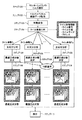
図3は、タイル画像Tl の分割の一例が示されており、タイル画像Tl は、縦方向に7分割、横方向に8分割し、合計56個のタイル画像Tl に分割し、すべて同一の画像サイズである。すべて同一の画像サイズとすることで、以降で述べる主成分分析や画像情報の作成における処理が容易となるためである。また、タイル画像Tl の縦方向および横方向の画像サイズとも、画素数を2の巾乗とするのが好ましい。圧縮した画像を再度呼び出して処理を行う際の便宜をはかるためである。
【0019】
本実施例では、タイル画像Tl はすべて同一の画像サイズであるが、必ずしも同一の画像サイズである必要はなく、例えば、背景が空や地面等であって、色相、明度や彩度の変化の少ない部分は、タイル画像Tl の画像サイズを大きくし、一方、被写体等を含み、色相、明度や彩度の変化の激しい部分は、画像サイズを小さくするといったように、画像内容に応じて適宜タイル画像Tl の画像サイズを変えてもよく、このように画像サイズを変えることによって圧縮率を高めることができる。
また、タイル画像Tl の総画像数が少なくとも構成波長数より大きい限りにおいて、タイル画像Tl の画像サイズや縦横比等は、特に制限されない。
【0020】
主成分分析部22cは、画像分割部22bから送られた分割情報および画像データ変換部22aから送られてきた対数変換画像データに基づいて、分割されたタイル画像Tl の対数変換タイル画像データを得、この対数変換タイル画像データに対して主成分分析を行い、分光反射率分布を対数変換した形で主成分に展開する部分である。なお、以降では、バンド数をnとして説明する。
本発明における主成分分析法は、観測波形データ群を正規直交展開して標本化する方法の一つで、最適標本化といわれるものである。即ち、最も少ない数の直交基底関数の加重平均で、観測波形データを最も精度良く表現するための方法である。ここでは、直交基底関数を主成分ベクトルと呼ぶ。
【0021】
本発明における主成分分析として具体的には、マルチスペクトル画像MS のタイル画像Tl (l=1〜nt )の対数変換タイル画像データの観測波形から、統計的手法および固有値解析法を用いて、観測波形に固有の1次独立な固有ベクトルを主成分ベクトルとして求め、この主成分ベクトルから、本来観測波形に雑音成分が無ければ、固有値が0となる固有値の小さな主成分ベクトルを取り除き、バンド数nより少ない数の最適主成分ベクトルを求め、この最適主成分ベクトルによって観測波形を線型的に表す、南茂夫著、「科学計測のための波形データ処理」、220−225頁に記載の方法が挙げられる。この分析方法は、主成分分析部22cおよび後述する最適主成分ベクトル・画像抽出部22dにおいて主に行われる。
主成分分析法を用いる場合には、分光反射率波形に含まれる雑音成分が、分光反射率の値と無関係な雑音であることが好ましい。
【0022】
本実施例に沿って説明すると、マルチスペクトル画像MS のタイル画像Tl (l=1〜nt )の対数変換タイル画像データは、可変フィルタ14を用いて被写体の撮影波長帯域を分割したバンドの数nだけ分光反射率分布の対数変換された値を有する。すなわちnバンドの数に相当するn個の構成波長を持ち、n個の分光反射率の値からなる対数値を有する。しかも、タイル画像Tl の総画素数は、構成波長数であるnよりも大きいため、画像の画素位置によらない統計的処理、すなわち、後述するように、n次元ベクトルの形式で表されたタイル画像Tl の分光反射率分布の対数変換タイル画像データR (i,j ,λ) =( R (i,j ,λ1),R(i,j,λ2),R(i,j,λ3),・・・,R(i,j ,λn ) )T (小文字T は転置を示し、(i,j) は、注目画素の画素位置であり、λは分光波長を示す)の、タイル画像Tl の画像領域全体の画素に関する自己相関行列Tを求めて、統計的に分光反射率の主成分分析を行うことができる。
【0023】
ここで、主成分分析されて求められる主成分は、統計的処理を用いて得られるもので、例えばnバンドの数に相当するn個の分光反射率の対数変換された値からなる正規直交化された自己相関行列Tの固有ベクトルである主成分ベクトルpk (λ)(k=1〜n)と自己相関行列Tの固有値uk (k=1〜n(kは1以上n以下の整数を示す))の対が求められる。また、主成分ベクトルpk (λ)(k=1〜n)を用いて、タイル画像Tl の画素位置(i,j) での分光反射率分布の対数変換タイル画像データR(i,j,λ) を線型展開し、その際得られる各主成分ベクトルpk (λ)(k=1〜n)に係る係数sk (i,j) (k=1〜n)を求め、これを画素位置(i,j) での画像データとする主成分画像Sk (k=1〜n)を得ることができる。
主成分分析は、タイル画像Tl (l=1〜nt )毎に行われ、得られたタイル画像Tl (l=1〜nt )毎の対数変換タイル画像データR(i,j,λ) の主成分ベクトルpk (λ)(k=1〜n)および主成分画像Sk (k=1〜n)は、最適主成分ベクトル・画像抽出部22dに送られる。
【0024】
最適主成分ベクトル・画像抽出部22dは、主成分分析部22bで得られたタイル画像Tl における対数変換タイル画像データR(i,j,λ) の主成分ベクトルpk (λ)(k=1〜n)(以降、タイル画像Tl における主成分ベクトルpk (λ)という)とそれに対応した主成分画像Sk (k=1〜n)とを用いて、各タイル画像Tl (l=1〜nt )毎に最適主成分数m1 を定め、各タイル画像Tl (l=1〜nt )毎に、最適主成分ベクトルpk (λ)(k=1〜m1 )および最適主成分画像のSk (k=1〜m1 )を抽出する部分である。
すなわち、n個のタイル画像Tl における主成分ベクトルpk (λ)(k=1〜n)とそれに対応した主成分画像Sk (k=1〜n)の対の中から、それより少ないm(m<n)個の主成分ベクトルpk (λ)(k=1〜m)とそれに対応した主成分画像Sk (k=1〜m)の対を用いて合成画像Gを求め、この合成画像Gの画像情報の、オリジナルのタイル画像Tl の画像情報に対する誤差を用いて、m個の主成分ベクトルpk (λ)(k=1〜m)とそれに対応した主成分画像Sk (k=1〜m)が最適な主成分であるかどうか判断する。
【0025】
ここで、タイル画像Tl における主成分ベクトルpk (λ)は、対応した固有値uk が大きい程、タイル画像Tl における寄与は大きい。すなわち、対応する固有値uk が大きい程、主成分ベクトルpk (λ)の、タイル画像Tl の分光反射率分布への寄与は大きい。そこで、主成分ベクトルpk (λ)を固有値uk の大きい順に並べ、合成画像Gを求めるために採用する主成分ベクトルを、固有値uk の大きい順に、順次増やし、一定の照明光源下て再構成される合成画像Gを求めていくと、n個の主成分ベクトルから構成されるオリジナルのタイル画像Tl に対する合成画像Gの画像情報の誤差が、採用する主成分ベクトル数mの増加に伴って単調減少する。そのため、この誤差が予め定めた所定値以下に減少する最初の主成分ベクトル数mを求めることによって、最小の最適主成分数m1 を求めることができる。これによって、最適主成分数m1 で合成画像Gを求める際に採用した主成分ベクトルおよびこれに基づいて得られる主成分画像を、それぞれ、タイル画像Tl における最適主成分ベクトルpk (λ)(k=1〜m1 )および最適主成分画像Sk (k=1〜m1 )として抽出することができる。この最適主成分ベクトルpk (λ)(k=1〜m1 )および最適主成分画像Sk (k=1〜m1 )は、タイル画像Tl 毎に求められる。
【0026】
ここで、上記画像情報とは、例えば、CIEL* a* b* 色空間に於ける一定の光源下の測色値L* 、a* およびb* 、例えばCIED65の標準光条件下の測色値L* 、a* およびb* であり、その際、上記誤差とは下記式(1) で表される色差ΔE0 である。この場合、この色差ΔE0 が例えば1.0以下となるような主成分画像の数mを見出すことによって最適主成分数m1 を求めることができる。
ΔE0 ={(ΔL* )2 +(Δa* )2 +(Δb* )2 }1/2 (1)
ここで、ΔL* 、Δa* およびΔb* は、上記合成画像Gとオリジナルのタイル画像Tl のタイル画像全体または一部分における平均測色値L* 、a* およびb* の差分である。このようにして、最適主成分数m1 は、合成画像Gの色空間上の測色値とオリジナル画像の測色値の色差ΔE0 に基づいて適応的に決定される。
【0027】
また、上記画像情報の誤差、すなわち、オリジナル画像に対するm個の主成分ベクトルpk (λ)によって構成される合成画像Gの、タイル画像全体または一部分の画素のスペクトルの自乗誤差E1 であってもよい。合成画像Gのバンド帯域に対応して分光情報を持つスペクトルの画像データについても、測色値の一例と見なすことができ、合成画像Gの色空間上の測色値であるスペクトルの画像データとオリジナル画像の測色値であるスペクトルの画像データの自乗誤差E1 に基づいて,最適主成分数m1 を適応的に決定してもよい。この場合、この自乗誤差E1 またはLog(E1 )は、主成分ベクトル数mに対して単調減少となるため、mを増やすことによって、自乗誤差E1 またはLog(E1 )の減少幅が予め定められた所定値より小さくなるmの値、すなわちmの増加に対して自乗誤差Eの減少が所定値以下で飽和する時の最小のmの値を求めればよい。
【0028】
得られた最適主成分数m1 、最適主成分ベクトルpk (λ)(k=1〜m1 )および最適主成分画像Sk (k=1〜m1 )のタイル情報は、画像分割部22bでタイル画像Tl に分割される際に作成されるタイル画像情報、すなわちタイル画像Tl のタイル番号、マルチスペクトル画像MS 上のタイル位置、タイル画像Tl のタイルサイズ(画像サイズ)および上記タイル情報のポインタ(アドレス)とともに圧縮画像データとして記録メディアドライブ装置24に送られる。
また、マルチスペクトル画像圧縮装置22は、マルチスペクトル画像データ全体を一度に画像データ変換部22aで対数変換して、主成分分析部22cに送る構成となっているが、画像分割されたタイル画像Tl 毎に対数変換して、主成分分析部22cに対数変換タイル画像データを送る構成としてもよい。
【0029】
本システム10は、以上のように構成される。
次に、本発明のマルチスペクトル画像の画像圧縮方法について、本システム10に沿った画像圧縮方法の流れを、図4を参照しつつ説明する。
【0030】
まず、光源12、可変フィルタ14およびCCDカメラ16によって形成されるマルチバンドカメラによって撮影被写体Oを撮影し、n個のバンド帯域に分割された複数のバンド画像からなるマルチバンド画像MB を取得する(ステップ100)。得られたマルチバンド画像MB は、マルチバンド画像データ記憶装置18に一時記憶されるると共に、マルチスペクトル画像取得装置20に送られる。
【0031】
マルチスペクトル画像取得装置20では、例えばマクベスチャートのグレーパッチの画像データとその分光反射率の値との関係から作成された1次元ルックアップテーブル(1次元LUT)が備えられており、この1次元LUTを用いて、マルチバンド画像データ記憶装置18から呼び出された撮影被写体Oのマルチバンド画像MB の画像データを用いて各画素毎の撮影被写体Oの分光反射率を推定しマルチスペクトル画像MS の画像データを取得する(ステップ102)。この撮影被写体Oの分光反射率の推定において、精度の高い分光反射率分布を推定するために、マトリクス演算やフーリエ変換を用いたデコンボリューション処理が付加されてもよい。
【0032】
次に、マルチスペクトル画像Ms の画像データを対数変換する。(ステップ103)。変換された対数変換タイル画像データは、主成分分析部22cに送られる。ここで、マルチスペクトル画像Ms の画像データに対数変換を行うのは以下の理由による。
すなわち、マルチスペクトル画像MS の画像データは、所定のピーク波長を中心とする急峻な山型分布を示す可変フィルタ14の分光透過特性に従って得られる画像データであるので、後述する様なタイル画像Tl の画像データの値は、実際、上記所定のピーク波長における光源12 の照明光の分光波長の強度分布の値と、撮影被写体Oの分光反射率分布の値と、CCDカメラ16の分光感度特性の値との積によって近似的に表されるが、対数変換を施すことによって、タイル画像Tl の対数変換画像データの値は、光源12 の照明光の分光波長の強度分布の値の対数値と、撮影被写体Oの分光反射率分布の値の対数値と、撮影被写体Oの分光反射率分布の値の対数値の和に分解され、後述する式(3)に示されるように、主成分分析において行われる主成分ベクトルの線型和に対応させることができるからである。
【0033】
一方、同一分光反射率を有する撮影被写体Oであっても、光源12の分光強度分布が異なる部分がある場合、対数変換の施されないタイル画像Tl の画像データでは、分光波長の強度分布の値と、撮影被写体Oの分光反射率分布の値と、CCDカメラ16の分光感度特性の値との積によって表されることから、主成分ベクトルpk (λ)の線型和で表現する主成分分析に対応して表現することはできず、従って、主成分数を大きくして、タイル画像Tl の画像データを表現しなければならず、本発明の目的である画像圧縮の際の圧縮効率を十分に高めることができない。
【0034】
次に、マルチスペクトル画像データを、タイル構造に分割(ステップ104)し、タイル画像Tl (l=1〜nt )を得る。また、その際、タイル画像Tl のタイル番号と、マルチスペクトル画像MS 上のタイル位置と、タイル画像Tl のタイルサイズ(画像サイズ)と、後述する最適主成分数m1 、最適主成分ベクトルpk (λ)および最適主成分画像Sk の画像データから成るタイル画像情報のポインタ(アドレス)を備えるヘッダ情報としてのタイル画像情報とを作成する。
タイル画像Tl (l=1〜nt )は、処理の容易さから図3に示すように、画像サイズはすべて同じであるが、圧縮率を高めるために、画像内容に応じて適宜、タイル画像Tl の画像サイズを変えてもよい。タイル画像Tl (l=1〜nt )の分割情報は、主成分分析部22cに送られる。
なお、本実施例では、マルチスペクトル画像データ全体を一度に対数変換するが、画像分割されたタイル画像Tl の画像データ毎に対数変換して、主成分分析してもよい。
【0035】
次に、タイル画像Tl (l=1〜nt )毎に、対数変換タイル画像データに基づいて主成分分析を行い(ステップ106)、主成分画像Sk (k=1〜n)および主成分ベクトルpk (λ)(k=1〜n)を求める。以下、主成分分析法について説明する。
【0036】
タイル画像Tl は、画素位置(i,j) においてそれぞれn個の分光反射率の値を持つ分光反射率分布の対数値を持つ対数変換タイル画像データを有し、この対数変換タイル画像データをR (i,j ,λ) =( R (i,j ,λ1),R(i,j,λ2),R(i,j ,λ3),・・・,R(i,j ,λn ) )T (小文字T は転置を示す))として、タイル画像全体の画素またはタイル画像の一部分、例えばタイル画像全体の画素から一定間隔で画素を間引いた残りの画素における自己相関行列Tを求める。
【0037】
得られた自己相関行列Tはn×nの正方行列であり、この自己相関行列Tを用いて、下記式(2)を満足する固有値uk (u1 >u2 >・・・>un ,k=1〜n)および正規直交化された固有ベクトルである主成分ベクトルpk (λ)=( pk (i,j ,λ1),pk (i,j,λ2),pk (i,j ,λ3),・・・,pk (i,j ,λn ) )T (k=1〜n)を求める。固有値および固有ベクトルを求める方法は、jacobi法やパワー法等の公知の方法であればよく、特に制限されない。
T・pk (λ)= uk pk (λ) (2)
また、画素位置(i,j) における対数変換タイル画像データR (i,j ,λ) が下記式(3)のように、固有ベクトルである主成分ベクトルpk (λ)(k=1〜n)で表されるため、
【数1】

sk (i,j) =R(i,j,λ) ・pk (λ) (4)
ここで、記号・は、n個の成分から成るバンド帯域の分光反射率の値についてのベクトルの内積であり、sk (i,j) は、マルチスペクトル画像の画素位置(i,j) での対数変換タイル画像データR(i,j, λ) に含まれる第k主成分ベクトルpk の大きさを示す量である。また、このsk (i,j) を各画素位置で求め、その値を各々の画素位置での画像データとする第k主成分画像Sk (k=1〜n)を求める。
【0038】
ところで、対数変換タイル画像データR(i,j,λ) における第1〜第nの各主成分の寄与は、上述したように、各主成分に付随した固有値uk の値が小さくなるに連れて小さくなることから、対数変換タイル画像データR(i,j,λ) は、画像情報を最適に保持する限りにおいて、小さな固有値uk を持つ主成分ベクトルpk を省略して近似することができる。
すなわち、下記式(5)に示すように、固有値uk (k=1〜n)を大きい順に並べた際の、上からm番目以内の固有値uk (k=1〜m)に対応する固有ベクトルである主成分ベクトルpk (λ) (k=1〜m)を採用し、それ以外の固有値uk の小さい固有ベクトルである主成分ベクトルpk (λ) (k=m+1〜n)を切り捨てることによって、対数変換タイル画像データR(i,j,λ) を近似し、画像データを圧縮することができる。
【数2】
そこで、対数変換タイル画像データR(i,j,λ) が、画像情報を損なうことなく、近似的に表されるような主成分ベクトルpk (λ) の採用数、すなわち最適主成分数m1 を見いだす。これによって、マルチスペクトル画像Ms の画質を劣化させることなく、画像データを圧縮することができる。
ここで、固有値uk の大きい固有ベクトルである主成分ベクトルpk (λ)(k=1〜m1 )を採用し、小さい固有ベクトルpk (λ)(k=m1 +1〜n)を切り捨てるための最適主成分数m1 の設定を以下の判断基準によって行なう(ステップ108)。
【0040】
まず、固有値uk の大きい順に主成分ベクトルpk (λ)を順次式(5)の主成分ベクトルpk (λ)に含め、下記式(6)で示されるマルチスペクトル画像に対応する近似対数変換タイル画像データR’(i,j,λ) を求める。
【数3】
近似対数変換タイル画像データR’(i,j,λ) は、対数変換タイル画像データR(i,j,λ) を近似しているため誤差が存在するが、この近似対数変換タイル画像データR’(i,j,λ) を真数変換した後、一定の分光強度分布を掛け合わせて得られる合成画像Gの画像情報の、タイル画像Tl の画像データに上記分光強度分布を掛け合わせて得られるオリジナルのタイル画像の画像情報に対する誤差は、主成分数mが大きくなるに連れて減少する。そこで、判断基準として、所定値を予め定め、近似対数変換タイル画像データR’(i,j,λ) を真数変換した後、分光強度分布を掛け合わせて得られる合成画像Gの画像情報の上記オリジナルのタイル画像Tl の画像情報に対する誤差が、上記判断基準として定めた所定値より小さくなる最初の主成分数mを求めることによって、最小の最適主成分数m1 を取得する。
【0042】
たとえば、合成画像Gの画像情報のマルチスペクトル画像MS の画像情報に対する誤差を、CIED65の標準光条件下のCIEL* a* b* 色空間における測色値L* 、a* およびb* の色差ΔE0 として、この色差ΔE0 に対する上記所定値を定め、最小の最適主成分数m1 を求める。
また、上記誤差は、合成画像Gのタイル画像全体または一部分のスペクトルの自乗誤差E1 であってもよく、その際、主成分数mの増加に対して自乗誤差E1 の減少量が所定値以内に飽和する時の最小の最適主成分数m1 の値を求めてもよい。
【0043】
このようにして、タイル画像Tl 毎の画像情報を保持し最適に代表する最小の最適主成分数m1 を求め、これによって、固有値u1 〜um1(u1 〜um1>um1>um1+1>・・・>un )に対応するm1 個の最適主成分ベクトルpk (λ)(k=1〜m1 )および最適主成分画像Sk (k=1〜m1 )を取得する。ここで、取り除かれる主成分ベクトルpk (λ)(k=m1 +1〜n)は、タイル画像Tl に含まれるノイズ成分が支配的な場合が比較的多く、タイル画像Tl から寄与の小さな主成分ベクトルpk (λ)(k=m1 +1〜n)を除去することで、マルチスペクトル画像Ms に含まれるノイズ成分の抑制も行うことができる。
【0044】
このようにして、ステップ108でタイル画像Tl (l=1〜nt )毎に、最適主成分数、最適主成分ベクトルpk (λ)と最適主成分画像Sk の画像データを得、ステップ104で作成されたタイル画像情報とともに、記録メディアドライブ装置24に送られて、ハードディスクやフロッピーディスクやMOやCD−RやDVD等の記録メディアに記録保存される(ステップ110)。特に、マルチスペクトル画像MS をタイル画像Tl に分割し、タイル画像Tl ごとに主成分分析を行っているので、色相、明度や彩度の変化の少ないタイル画像Tl の場合、最適主成分数m1 は1または2で済み、すなわち、1個または2個の最適主成分ベクトルpk によって画像情報を保持し最適に代表することができる。そのため、マルチスペクトル画像MS の画像品質を落すことなく画像データの画像圧縮率を高めることができる。
【0045】
特に、上述した様に、対数変換タイル画像データR(i,j,λ) は、タイル画像Tl の画像データを対数変換して、分光波長の強度分布の対数値と、撮影被写体Oの分光反射率分布の対数値の和で表すことができるので、撮影被写体Oの分光反射率が同一の部分であるが、光源12の照明強度が異なる部分が存在する場合、例えば、撮影被写体Oの同一の材質の表面上に照明光による陰影部分がある場合、撮影被写体Oの同一の材質の分光反射率分布の対数変換された画像データの主成分ベクトルpk (λ)に、照明光の陰影部分による分光強度分布の対数変換されたバイアス量分、加算されたデータとなる。そのため、主成分ベクトルの線型和で表す主成分分析法において、撮影被写体Oの分光反射率に基づく主成分を、対数変換した状態で、照明光の分光強度分布によるバイアス量と区別して効果的に抽出するこができる。その結果、対数変換せずに主成分分析を行う場合に比べて、最適主成分数m1 を小さくすることができ、本発明の目的とする画像の圧縮率を高めることができる。
【0046】
なお、ステップ108で最適主成分数m1 を決定して、最適主成分ベクトルpk (λ)(k=1〜m1 )および最適主成分画像Sk (k=1〜m1 )を求めたのち、最適主成分画像Sk (k=1〜m1 )について、さらにJPEG(Joint Photographics Expert Group) 方式等によって更に画像圧縮を行ってもよく、ハフマン符号化や公知の算術符号化によって、さらに画像圧縮を行ってもよい。
【0047】
また、圧縮され記録メディア等に保存された画像データは、必要に応じて呼び出され、最適主成分ベクトルpk (λ)(k=1〜m1 )最適主成分画像Sk (k=1〜m1 )およびタイル番号やタイル位置やタイルサイズ等のタイル画像情報が得られ、タイル画像Tl 毎に最適主成分ベクトルpk (λ)および最適主成分画像Sk から、近似対数変換画像データR’(i,j,λ) が求められ、最後に真数変換を行ってタイル画像Tl の画像データが得られ、最終的に1つのマルチスペクトル画像の画像データが求められる。
【0048】
このようなマルチスペクトル画像の画像圧縮方法および画像圧縮装置において、以下のようなマルチスペクトル画像の圧縮を行った。
CCDカメラ16として、DALSA社製 CA-D4-1024A(画素数1024×1024、ピクセルサイズ12×12ミクロン、PCIインターフェース付き、モノクロ)を用い、可変フィルタ14として、CRI社製Varispec Tunable Filter (液晶チューナブルフィルタ)を用いた。この液晶チューナブルフィルタによって、380〜780nmの撮影波長帯域を、バンド帯域幅を5nmずつに分割し、41バンド(n=41)とした。屋外の人物を撮影被写体Oとし、41画像から成る人物画のマルチバンド画像MB を得た。
マルチバンド画像記憶部18、マルチスペクトル画像取得装置20およびマルチスペクトル画像圧縮装置22は、PROSIDE社製ブック型PC(パーソナルコンピュータ)を用いて構成し、Windows 95上でC++言語によるソフトウェア処理を行った。なお、PROSIDE社製ブック型PCは、CPUが166MHz であり、RAMは128Mbyte であった。
なお、前処理として、ソフトウェア処理の都合上から、画像データの量子化数を2バイトから1バイトに変換した。この前処理は、以降で述べる画像データ量の圧縮には含まれていないものである。
【0049】
まず、マルチスペクトル画像取得装置20において、マルチバンド画像MB から構成波長数41のマルチスペクトル画像MS を抽出し、得られた1024×1024画素の画像サイズのマルチスペクトル画像MS を16×16画素の画像サイズのタイル画像Tl (l=1〜4096)に分割した。
各タイル画像Tl (l=1〜4096)に対して主成分分析を行い、主成分ベクトルpk (λ)(k=1〜41)および主成分画像Sk (k=1〜41)を求めた。
【0050】
次に、最適主成分数m1 を求めるために、判断基準として、CIED65の標準光源下のCIED1976L* a* b* 色空間における色度に基づく平均色差を1.5とした。さらに、上述した主成分分析法によって得られた固有値uk の大きい順に、固有値uk に対応した主成分ベクトルpk を順次採用し、採用されたm個の主成分ベクトルpk (λ)(k=1〜m)によって再構成される合成画像Gと各タイル画像Tl から得られるオリジナル画像との上記平均色差を求め、平均色差が1.5以下となる最適主成分数m1 を決定した。
【0051】
その結果、タイル画像Tl (l=1〜4096)の最適主成分数m1 は2〜6であった。特に、図3で示されるタイル画像TB のような色相、明度や彩度の変化が小さく、撮影被写体Oである人物の背景としての空部分のタイル画像Tl や同一色相、明度や彩度を有するタイル画像Tl は、タイル画像TA に比べて最適主成分数m1 は小さく、値として2でよく、つまり第1主成分ベクトルp1 (λ)および第2主成分ベクトルp2 (λ)でタイル画像Tl を表すことができた。さらに、上述した平均色差1.5の基準を緩和した場合でも、第1主成分ベクトルp1 (λ)のみでも十分に画像情報を最適に保持し代表できることがわかった。
【0052】
次に、各タイル画像Tl の最適主成分数m1 、最適主成分ベクトルp(λ)および最適主成分画像Sk にタイル画像情報、すなわち、タイル画像Tl のタイル番号と、マルチスペクトル画像MS 上のタイル位置と、タイル画像Tl のタイルサイズ(画像サイズ)と、上記最適主成分数m1 、最適主成分ベクトルpk (λ)および最適主成分画像Sk の画像データから成るタイル情報のポインタ(アドレス)とを付加し、記録メディアドライブ装置24を介して、記録保存した。
その結果、画像データは、約41Mバイトから3.5Mバイトに低減し、画像データは約1/12に圧縮された。さらに、この圧縮された画像データを再度呼び出して画像を再構成してみたが、視覚的に画質の劣化は認められなかった。
【0053】
このように、本発明の画像圧縮方法およびこれを用いた画像圧縮装置は、複数のスペクトル画像に対して、視覚的な劣化が少なく画像圧縮の際の圧縮率を高め、例えば 1/12程度に高め、画像データの取り扱いを向上するのは明らかである。
【0054】
以上、本発明のマルチスペクトル画像の画像圧縮方法および画像圧縮装置について詳細に説明したが、本発明は上記実施例に限定はされず、本発明の要旨を逸脱しない範囲において、各種の改良および変更を行ってもよいのはもちろんである。
【0055】
【発明の効果】
以上、詳細に説明したように、本発明によれば、画像データ量の大きなマルチスペクトル画像をタイル画像に分割し、しかも、主成分ベクトルの線型和で表される主成分分析法に合わせた形でタイル画像データを対数変換して主成分分析を行うので、画像品質を損なうことなく、画像の高度な圧縮が可能であり、画像データの取り扱いを向上させることができる。
また、タイル画像に基づく主成分ベクトルからノイズ成分が支配的な主成分ベクトルを除去することができ、ノイズ成分の抑制も行うことができる。
【図面の簡単な説明】
【図1】 本発明のマルチスペクトル画像圧縮装置を含むマルチスペクトル画像取得システムの一例を示す概念図である。
【図2】 本発明に係るマルチスペクトル画像圧縮装置の一例を示すブロック図である。
【図3】 本発明のマルチスペクトル画像圧縮方法で行う画像分割の一例を示す説明図である。
【図4】 本発明のマルチスペクトル画像圧縮方法のフローの一例を示すフローチャートである。
【符号の説明】
10 マルチスペクトル画像取得システム
12 光源
14 可変フィルタ
16 CCDカメラ
18 マルチバンド画像データ記憶装置
20 マルチスペクトル画像取得装置
22 マルチスペクトル画像圧縮装置
22a 画像データ変換部
22b 画像分割部
22c 主成分分析部
22d 最適主成分ベクトル・画像抽出部
24 記録メディアドライブ装置[0001]
BACKGROUND OF THE INVENTION
The present invention does not impair image quality with respect to image data of a multispectral image obtained by using a plurality of band images obtained by dividing a shooting wavelength region when shooting a subject into a plurality of band bands. The present invention relates to a technical field of image data compression processing that can be efficiently compressed.
[0002]
[Prior art]
Today, with the advancement of digital image processing, as a means for completely expressing color information (lightness, hue, saturation) of an image, an image having spectral information (spectral image) for each pixel of the image, that is, a multispectral image is used. It's being used.
In this multispectral image, a spectral reflectance distribution is estimated for each image based on a multiband image composed of a plurality of band images obtained by dividing a photographed subject into a plurality of band bands and photographed for each band band. Is obtained. This multiband image can reproduce color information that cannot be sufficiently expressed by a conventional RGB color image composed of red (R), green (G), and blue (B) images. For example, more accurate color reproduction is desired. It is effective for the world of painting. Therefore, in order to take advantage of the feature of accurately reproducing this color information, for example, the 380 to 780 nm imaging wavelength band is divided into 10 nm bands and divided into 41 bands, further divided into 5 nm bands and 81 bands. It is desired to obtain a multispectral image based on the provided multiband image.
[0003]
However, since a multispectral image having spectral information for each pixel has spectral reflectance data for each band (channel) obtained by dividing the imaging wavelength band, for example, for every 41 channels, the conventional three-channel image has been used. Compared to the RGB color image, for example, the image data amount must be about 13 times (41 channels / 3 channels).
Therefore, when storing the image data of the obtained multispectral image, a large storage capacity is required and the time required for the storage is long. Also, it takes a lot of time to transfer image data via a network, and handling becomes difficult.
[0004]
To solve such a problem, a spectral waveform obtained from spectral information for each pixel of a multispectral image is developed with three color matching functions, for example, a color matching function of RGB color form, and is not represented with a color matching function. Using the principal component analysis method, the spectral waveform part is expanded with the principal component basis vectors, and the principal components that represent the image information of the spectral image are extracted and adopted, and the other principal components are removed. Finally, a method of expressing the above spectrum waveform with a total of 6 to 8 basis vectors including color matching functions has been proposed (Th. Keusen, Multispectoral Color System, Wuth an Encoding Format Compatible with the Conventional Tristimulus Model, Journal of Imaging Science and Technology 40: 510-515 (1996)). By using this, the image data of the multispectral image can be compressed by expressing the spectrum waveform with 6 to 8 basis vectors and pairs of coefficients corresponding thereto. In particular, the coefficient of the color matching function represented by the color matching function of the RGB color specification is tristimulus values of R, G, and B. Excellent effect on reduction of processing such that image data can be sent directly without the need for special conversion to be compatible with conventional image processing devices and image display devices that display images Is provided.
[0005]
[Problems to be solved by the invention]
For example, in the case of a multispectral image composed of 41 spectral images, the image data obtained by such a method is represented by, for example, eight basis vectors and their coefficients, thereby reducing the amount of image data of the multispectral image. It can be compressed to 20% (8 pieces / 41 pieces × 100).
However, in the case of a multispectral image composed of 41 spectral images, the amount of image data of the RGB color image is about 13 times larger than that of the RGB color image. The amount of data is still about 2.5 times (13 × 20/100) the amount of image data. For this reason, as described above, the recording time when recording and saving on a recording medium or the like, and the transfer time when transferring image data via a network are long, and handling is still difficult.
[0006]
Therefore, the present invention solves the above-described problems, and is less likely to be visually degraded with respect to a plurality of spectral images obtained by dividing a photographing wavelength band when photographing a subject into a plurality of band bands. It is an object of the present invention to provide an image compression method and an image compression apparatus for multispectral images that can increase the compression rate during image compression and improve the handling of image data.
[0007]
[Means for Solving the Problems]
In order to achieve the above object, the present invention is a method of compressing a multispectral image obtained by using a band image obtained by dividing a shooting wavelength band into a plurality of band bands when shooting a subject. ,
Dividing the multispectral image into a plurality of tile images, logarithmically converting the image data of the tile images to obtain logarithmically converted tile image data;
Alternatively, logarithmically transform the multispectral image, divide the multispectral image into tile images to obtain logarithmically transformed tile image data,
Performing principal component analysis for each logarithmically transformed tile image data, obtaining multiple pairs of principal component vectors and principal component images based on multispectral images for each tile image,
From these pairs, the optimum principal component number of the principal component vector and principal component image pair that best represents the image information of the multispectral image is obtained, and the optimum principal component vector and the corresponding optimum principal component image are obtained. Obtained for each tile image,
Provided is an image compression method for a multispectral image, wherein the compressed image data of the multispectral image is expressed using at least the optimum principal component image, the optimum principal component vector, and the optimum number of principal components. .
[0008]
Here, the compressed image data of the multispectral image includes the tile number of the tile image, the tile position, and the image size of the tile image in addition to the optimum principal component image, the optimum principal component vector, and the optimum principal component number. It is preferable that the information is expressed using tile image information having the following information.
The optimum number of principal components is preferably determined based on a colorimetric value in a color space, and the optimum number of principal components is selected from a pair of the principal component vector and the principal component image. It is preferable that the value of the error of the image information of the composed image configured with respect to the image information of the original image configured based on the multispectral image is the minimum number of principal components that is equal to or less than a predetermined value. The optimum number of principal components is a predetermined error variation with respect to the original image when the composite image is obtained by sequentially including principal component vectors having a large contribution to the multispectral image in the order of principal components vectors having a large contribution. It is preferable that the minimum number of main components fall below the value.
The pixel size of the tile image is preferably a power of 2 in both the vertical direction and the horizontal direction, and the pixel sizes of the tile image are preferably all the same size.
[0009]
The present invention is also a multispectral image compression apparatus for compressing a multispectral image obtained by using a band image obtained by dividing a photographing wavelength band into a plurality of band bands when photographing a subject. ,
An image dividing unit for dividing the multispectral image into a plurality of tile images;
An image data conversion unit for logarithmically converting the image data of the multispectral image or the tile image obtained by the image dividing unit;
A principal component analysis is performed for each tile image on logarithmically transformed tile image data obtained through the image dividing unit and the image data converting unit, and a plurality of pairs of principal component vectors and principal component images of a multispectral image are obtained. A principal component analysis unit for obtaining
Among the multiple pairs of principal component vectors and principal component images obtained by this principal component analysis unit, the optimum number of principal components of the principal component vector and principal component image pair that best represents the image information of the multispectral image is determined. And obtaining an optimum principal component vector and an optimum principal component vector / image extraction unit for obtaining an optimum principal component image,
The image data of the multispectral image is at least the optimum main Provided is an image compression apparatus for multispectral images, wherein compression is performed using an optimum principal component vector of each tile image obtained by a component vector / image extraction unit and image data of the optimum principal component image. is there.
[0010]
DETAILED DESCRIPTION OF THE INVENTION
Hereinafter, a multispectral image acquisition system for performing an image compression method of a multispectral image of the present invention will be described in detail based on a preferred embodiment shown in the accompanying drawings.
[0011]
FIG. 1 shows a multispectral image acquisition system (hereinafter referred to as the present system) 10 that implements the multispectral image compression method of the present invention and includes the multispectral image compression apparatus of the present invention.
The
[0012]
The
The
[0013]
The
In addition, the
[0014]
The multiband image
The
In the estimation of the spectral reflectance of the photographic subject O, when the filter characteristics of the
In this way, the multiband image M divided into n band bands using the
[0015]
The recording
[0016]
The multispectral
[0017]
The image
The
[0018]
FIG. 3 shows a tile image T l An example of the division of the tile image T is shown. l Is divided into 7 in the vertical direction and 8 in the horizontal direction, for a total of 56 tile images T l Are all the same image size. This is because, by setting all the images to the same size, processing in the principal component analysis and creation of image information described below is facilitated. Tile image T l For both the vertical and horizontal image sizes, the number of pixels is preferably a power of two. This is for the convenience of recalling the compressed image and performing processing.
[0019]
In this embodiment, the tile image T l Are all the same image size, but are not necessarily the same image size. For example, the background is the sky, the ground, etc., and the portion where the change in hue, brightness, and saturation is small is the tile image T l On the other hand, the tile image T is appropriately selected according to the image content, such as reducing the image size in a portion where the hue, brightness, or saturation changes drastically, including the subject or the like. l The image size may be changed, and the compression rate can be increased by changing the image size in this way.
Tile image T l As long as the total number of images of the image is at least larger than the number of constituent wavelengths, the tile image T l The image size, aspect ratio, etc. are not particularly limited.
[0020]
The principal
The principal component analysis method according to the present invention is one of methods for sampling an observed waveform data group by normal orthogonal expansion, and is called optimal sampling. That is, this is a method for expressing the observed waveform data with the highest accuracy by the weighted average of the smallest number of orthogonal basis functions. Here, the orthogonal basis function is called a principal component vector.
[0021]
Specifically, as the principal component analysis in the present invention, the multispectral image M S Tile image T l (L = 1 to n t ) Using the statistical method and eigenvalue analysis method, the primary independent eigenvector unique to the observed waveform is obtained as the principal component vector from the observed waveform of the logarithmic transformation tile image data of). If there is no noise component, the small principal component vector having an eigenvalue of 0 is removed, the optimum principal component vector having a number smaller than the number of bands n is obtained, and the observed waveform is linearly represented by this optimum principal component vector. The method described in the book, “Waveform data processing for scientific measurement”, pp. 220-225. This analysis method is mainly performed in the principal
When the principal component analysis method is used, it is preferable that the noise component included in the spectral reflectance waveform is noise unrelated to the spectral reflectance value.
[0022]
To explain along the present embodiment, the multispectral image M S Tile image T l (L = 1 to n t The logarithmic conversion tile image data of () has a logarithmically converted value of the spectral reflectance distribution by the number n of bands obtained by dividing the imaging wavelength band of the subject using the
[0023]
Here, the principal component obtained by the principal component analysis is obtained using statistical processing. For example, orthonormalization including logarithmically transformed values of n spectral reflectances corresponding to the number of n bands is performed. Principal component vector p, which is the eigenvector of the correlated autocorrelation matrix T k (Λ) (k = 1 to n) and the eigenvalue u of the autocorrelation matrix T k A pair of k = 1 to n (k is an integer of 1 to n) is obtained. The principal component vector p k Using (λ) (k = 1 to n), the tile image T l Logarithmically transformed tile image data R (i, j, λ) of the spectral reflectance distribution at the pixel position (i, j) of the pixel is linearly expanded and each principal component vector p obtained at that time is obtained. k Coefficient s according to (λ) (k = 1 to n) k (i, j) (k = 1 to n) is obtained, and this is used as image data at the pixel position (i, j). k (K = 1 to n) can be obtained.
Principal component analysis is based on tile image T l (L = 1 to n t ) Tile image T obtained every time l (L = 1 to n t ) Principal component vector p of logarithmic transformation tile image data R (i, j, λ) for each) k (Λ) (k = 1 to n) and principal component image S k (K = 1 to n) is sent to the optimum principal component vector /
[0024]
The optimum principal component vector /
That is, n tile images T l Principal component vector p k (Λ) (k = 1 to n) and the corresponding principal component image S k From the (k = 1 to n) pairs, fewer m (m <n) principal component vectors p k (Λ) (k = 1 to m) and the corresponding principal component image S k A composite image G is obtained using a pair (k = 1 to m), and the original tile image T of the image information of the composite image G is obtained. l M principal component vectors p using the error for the image information of k (Λ) (k = 1 to m) and the corresponding principal component image S k It is determined whether (k = 1 to m) is the optimum principal component.
[0025]
Here, the tile image T l Principal component vector p k (Λ) is the corresponding eigenvalue u k The larger the is, the tile image T l The contribution in is large. That is, the corresponding eigenvalue u k Is larger, the principal component vector p k Tile image T of (λ) l Greatly contributes to the spectral reflectance distribution. Therefore, the principal component vector p k (Λ) is the eigenvalue u k The principal component vectors used for obtaining the composite image G are arranged in descending order of the eigenvalue u. k When the composite image G that is sequentially increased and reconstructed under a certain illumination light source is obtained, the original tile image T composed of n principal component vectors is obtained. l The error of the image information of the composite image G with respect to increases monotonously with the increase in the number m of principal component vectors employed. Therefore, the minimum optimum principal component number m is obtained by obtaining the first principal component vector number m in which this error decreases below a predetermined value. 1 Can be requested. As a result, the optimum number of principal components m 1 The principal component vector employed when the composite image G is obtained in step 1 and the principal component image obtained based on the principal component vector are respectively represented by the tile image T. l Optimal principal component vector p k (Λ) (k = 1 to m 1 ) And the optimal principal component image S k (K = 1 to m 1 ) Can be extracted. This optimal principal component vector p k (Λ) (k = 1 to m 1 ) And the optimal principal component image S k (K = 1 to m 1 ) Is the tile image T l Required every time.
[0026]
Here, the image information is, for example, CIEL * a * b * Colorimetric value L under a certain light source in the color space * , A * And b * For example, CIED 65 Colorimetric value L under standard light conditions * , A * And b * In this case, the error is a color difference ΔE represented by the following formula (1). 0 It is. In this case, this color difference ΔE 0 For example, the optimal number m of principal components is found by finding the number m of principal component images such that the value is 1.0 or less. 1 Can be requested.
ΔE 0 = {(ΔL * ) 2 + (Δa * ) 2 + (Δb * ) 2 } 1/2 (1)
Where ΔL * , Δa * And Δb * Is the composite image G and the original tile image T l Average colorimetric value L over all or part of the tile image * , A * And b * Difference. In this way, the optimum number of principal components m 1 Is the color difference ΔE between the colorimetric value in the color space of the composite image G and the colorimetric value of the original image. 0 Is adaptively determined based on
[0027]
Further, the error of the image information, that is, m principal component vectors p with respect to the original image k The square error E of the spectrum of the pixel of the entire tile image or a part of the composite image G composed of (λ). 1 It may be. The spectral image data having spectral information corresponding to the band band of the composite image G can also be regarded as an example of the colorimetric value. Square error E of spectral image data, which is the colorimetric value of the original image 1 Based on the optimal number of principal components m 1 May be determined adaptively. In this case, this square error E 1 Or Log (E 1 ) Is monotonically decreasing with respect to the number m of principal component vectors. 1 Or Log (E 1 The minimum value of m when the decrease of the square error E is saturated below a predetermined value with respect to the increase of m, that is, the value of m that is smaller than a predetermined value determined in advance.
[0028]
Obtained optimum number of principal components m 1 , Optimal principal component vector p k (Λ) (k = 1 to m 1 ) And the optimal principal component image S k (K = 1 to m 1 The tile information T) is obtained by the
The multispectral
[0029]
The
Next, the flow of the image compression method along the
[0030]
First, a photographic subject O is photographed by a multiband camera formed by the
[0031]
The multispectral
[0032]
Next, the multispectral image M s Logarithmically convert the image data. (Step 103). The converted logarithmic conversion tile image data is sent to the principal
That is, the multispectral image M S Since the image data is image data obtained according to the spectral transmission characteristics of the
[0033]
On the other hand, even if the subject O has the same spectral reflectance, if there is a portion where the spectral intensity distribution of the
[0034]
Next, the multispectral image data is divided into tile structures (step 104), and the tile image T l (L = 1 to n t ) At that time, the tile image T l Tile number and multispectral image M S Top tile position and tile image T l Tile size (image size) and the optimum number of principal components m described later 1 , Optimal principal component vector p k (Λ) and the optimal principal component image S k Tile image information as header information having a pointer (address) of tile image information made up of the image data.
Tile image T l (L = 1 to n t ) Are all the same image size as shown in FIG. 3 because of the ease of processing, but in order to increase the compression rate, the tile image T is appropriately selected according to the image content. l You may change the image size. Tile image T l (L = 1 to n t ) Division information is sent to the principal
In this embodiment, the entire multispectral image data is logarithmically converted at a time, but the tile image T divided into images is divided. l The principal component analysis may be performed by logarithmic conversion for each image data.
[0035]
Next, tile image T l (L = 1 to n t ), Principal component analysis is performed based on the logarithmic transformation tile image data (step 106), and the principal component image S k (K = 1 to n) and principal component vector p k (Λ) (k = 1 to n) is obtained. Hereinafter, the principal component analysis method will be described.
[0036]
Tile image T l Has logarithmic conversion tile image data having logarithmic values of spectral reflectance distributions each having n spectral reflectance values at the pixel position (i, j), and this logarithmic conversion tile image data is represented by R (i, j j, λ) = (R (i, j, λ 1 ), R (i, j, λ 2 ), R (i, j, λ Three ), ..., R (i, j, λ n )) T (Lowercase T Represents a transposition)), and an autocorrelation matrix T is obtained for the pixels of the entire tile image or a part of the tile image, for example, the remaining pixels obtained by thinning out pixels at regular intervals from the pixels of the entire tile image.
[0037]
The obtained autocorrelation matrix T is an n × n square matrix, and using this autocorrelation matrix T, an eigenvalue u that satisfies the following equation (2): k (U 1 > U 2 >...> u n , K = 1 to n) and the principal component vector p which is an orthonormalized eigenvector k (Λ) = (p k (i, j, λ 1 ), P k (i, j, λ 2 ), P k (I, j, λ Three ), ..., p k (I, j, λ n )) T (K = 1 to n) is obtained. The method for obtaining eigenvalues and eigenvectors is not particularly limited as long as it is a known method such as the jacobi method or the power method.
T ・ p k (Λ) = u k p k (Λ) (2)
Also, the logarithmic transformation tile image data R (i, j, λ) at the pixel position (i, j) is a principal component vector p that is an eigenvector as shown in the following equation (3). k Since (λ) (k = 1 to n),
[Expression 1]
s k (i, j) = R (i, j, λ) ・ p k (Λ) (4)
Here, the symbol “·” is an inner product of vectors of spectral reflectance values in a band band composed of n components, and s k (i, j) is the k-th principal component vector p included in the logarithmic transformation tile image data R (i, j, λ) at the pixel position (i, j) of the multispectral image. k It is an amount indicating the size of. This s k (i, j) is obtained at each pixel position, and the k-th principal component image S having the value as image data at each pixel position. k (K = 1 to n) is obtained.
[0038]
Incidentally, the contribution of the first to n-th principal components in the logarithmic transformation tile image data R (i, j, λ) is, as described above, the eigenvalue u associated with each principal component. k Logarithmically transformed tile image data R (i, j, λ) has a small eigenvalue u as long as the image information is optimally held. k Principal component vector p with k Can be approximated by omitting.
That is, as shown in the following formula (5), the eigenvalue u k Eigenvalue u within mth from the top when (k = 1 to n) are arranged in descending order k Principal component vector p which is an eigenvector corresponding to (k = 1 to m) k (Λ) (k = 1 to m) is adopted, and other eigenvalues u k Principal component vector p which is a small eigenvector of k By truncating (λ) (k = m + 1 to n), logarithmically transformed tile image data R (i, j, λ) can be approximated and the image data can be compressed.
[Expression 2]
Therefore, the principal component vector p such that the logarithmic transformation tile image data R (i, j, λ) is approximately represented without impairing the image information. k Number of adopted (λ), that is, optimum number of principal components m 1 Find out. As a result, the multispectral image M s The image data can be compressed without degrading the image quality.
Where eigenvalue u k Principal component vector p which is a large eigenvector k (Λ) (k = 1 to m 1 ) And a small eigenvector p k (Λ) (k = m 1 Optimal number of principal components m for rounding down +1 to n) 1 Is set according to the following criteria (step 108).
[0040]
First, the eigenvalue u k Principal component vector p in descending order of k (Λ) in turn is the principal component vector p of equation (5) k Included in (λ), approximate logarithmic transformation tile image data R ′ (i, j, λ) corresponding to the multispectral image represented by the following equation (6) is obtained.
[Equation 3]
The approximate logarithmic transformation tile image data R ′ (i, j, λ) has an error because it approximates the logarithmic transformation tile image data R (i, j, λ). Tile image T of the image information of composite image G obtained by multiplying '(i, j, λ) by a true number and then multiplying by a constant spectral intensity distribution l The error with respect to the image information of the original tile image obtained by multiplying the image data by the above spectral intensity distribution decreases as the number of principal components m increases. Therefore, as a criterion for judgment, a predetermined value is set in advance, and the logarithmic intensity distribution of the approximate logarithm-transformed tile image data R ′ (i, j, λ) is subjected to a logarithmic transformation, and then the image information of the composite image G obtained by multiplying the spectral intensity distribution is obtained. The original tile image T l By calculating the first principal component number m in which the error with respect to the image information is smaller than the predetermined value set as the above-mentioned criterion, the minimum optimum principal component number m 1 To get.
[0042]
For example, the multispectral image M of the image information of the composite image G S The error for the image information of CIED 65 CIEL under standard light conditions * a * b * Colorimetric value L in color space * , A * And b * Color difference ΔE 0 This color difference ΔE 0 The above-mentioned predetermined value for is determined, and the minimum optimum number of principal components m 1 Ask for.
Further, the error is the square error E of the spectrum of the entire tile image or a part of the composite image G. 1 In this case, the square error E with respect to the increase in the number of principal components m. 1 Minimum optimal number of principal components m when the amount of decrease is saturated within a predetermined value 1 May be obtained.
[0043]
In this way, the tile image T l The smallest optimal number of principal components m that holds and best represents image information 1 , So that the eigenvalue u 1 ~ U m1 (U 1 ~ U m1 > U m1 > U m1 + 1 >...> u n M corresponding to 1 Optimal principal component vectors p k (Λ) (k = 1 to m 1 ) And the optimal principal component image S k (K = 1 to m 1 ) To get. Where the principal component vector p to be removed k (Λ) (k = m 1 +1 to n) are tile images T l The noise component included in the tile image T l The principal component vector p with a small contribution k (Λ) (k = m 1 By removing +1 to n), the multispectral image M s The noise component contained in can also be suppressed.
[0044]
Thus, in step 108, the tile image T l (L = 1 to n t ), The optimum number of principal components, the optimum principal component vector p k (Λ) and the optimal principal component image S k And the tile image information created in step 104 together with the tile image information is sent to the
[0045]
In particular, as described above, the logarithmic transformation tile image data R (i, j, λ) l The logarithmic conversion of the image data of the photographic subject O can be represented by the sum of the logarithmic value of the intensity distribution of the spectral wavelength and the logarithmic value of the spectral reflectance distribution of the photographic subject O. However, when there is a portion where the illumination intensity of the
[0046]
In step 108, the optimum number of principal components m 1 And determine the optimal principal component vector p k (Λ) (k = 1 to m 1 ) And the optimal principal component image S k (K = 1 to m 1 ) And then the optimum principal component image S k (K = 1 to m 1 ) May be further compressed by JPEG (Joint Photographics Expert Group) method or the like, or may be further compressed by Huffman coding or known arithmetic coding.
[0047]
Also, the image data compressed and stored in the recording medium or the like is called as necessary, and the optimum principal component vector p k (Λ) (k = 1 to m 1 ) Optimal principal component image S k (K = 1 to m 1 ) And tile image information such as tile number, tile position and tile size is obtained, and the tile image T l Optimal principal component vector p for each k (Λ) and the optimal principal component image S k From this, approximate logarithmic transformation image data R ′ (i, j, λ) is obtained, and finally, a true number transformation is performed to obtain a tile image T l The image data of one multispectral image is finally obtained.
[0048]
In such a multispectral image compression method and image compression apparatus, the following multispectral image was compressed.
A CA-D4-1024A manufactured by DALSA (pixel number: 1024 × 1024, pixel size: 12 × 12 microns, with a PCI interface, monochrome) is used as the
The multiband
As preprocessing, the quantization number of the image data is converted from 2 bytes to 1 byte for the convenience of software processing. This preprocessing is not included in the compression of the image data amount described below.
[0049]
First, in the multispectral
Each tile image T l Principal component analysis is performed on (l = 1 to 4096), and the principal component vector p k (Λ) (k = 1 to 41) and principal component image S k (K = 1 to 41) was determined.
[0050]
Next, the optimum number of principal components m 1 CIED as a criterion for determining 65 CIED 1976L under standard light source * a * b * The average color difference based on the chromaticity in the color space was 1.5. Further, the eigenvalue u obtained by the principal component analysis method described above. k Eigenvalue u in descending order of k Principal component vector p corresponding to k Are adopted sequentially, and m principal component vectors p adopted k The combined image G and each tile image T reconstructed by (λ) (k = 1 to m) l The average color difference from the original image obtained from the above is obtained, and the optimum number of main components m for which the average color difference is 1.5 or less 1 It was determined.
[0051]
As a result, the tile image T l Optimum number of principal components m (l = 1 to 4096) 1 Was 2-6. In particular, the tile image T shown in FIG. B The tile image T of the sky as the background of the person who is the subject O is small and changes in hue, brightness, and saturation are small. l Tile image T with the same hue, brightness and saturation l Tile image T A Compared to the optimal number of principal components m 1 Is small and may have a value of 2, that is, the first principal component vector p 1 (Λ) and the second principal component vector p 2 Tile image T at (λ) l Could be represented. Further, even when the above-described criterion of the average color difference of 1.5 is relaxed, the first principal component vector p 1 It was found that the image information can be held optimally and represented by (λ) alone.
[0052]
Next, each tile image T l The optimal number of principal components of m 1 , Optimum principal component vector p (λ) and optimum principal component image S k Tile image information, that is, tile image T l Tile number and multispectral image M S Top tile position and tile image T l Tile size (image size) and the optimal number of principal components m 1 , Optimal principal component vector p k (Λ) and the optimal principal component image S k A pointer (address) of tile information made up of the image data is added and recorded via the recording
As a result, the image data was reduced from about 41 Mbytes to 3.5 Mbytes, and the image data was compressed to about 1/12. Further, the compressed image data was recalled and the image was reconstructed, but no visual deterioration was observed.
[0053]
As described above, the image compression method and the image compression apparatus using the image compression method according to the present invention increase the compression ratio at the time of image compression with little visual deterioration with respect to a plurality of spectral images, for example, about 1/12. Obviously, it improves and improves the handling of image data.
[0054]
The multispectral image compression method and image compression apparatus according to the present invention have been described in detail above. However, the present invention is not limited to the above embodiments, and various improvements and modifications can be made without departing from the scope of the present invention. Of course, you may also do.
[0055]
【The invention's effect】
As described above in detail, according to the present invention, a multispectral image having a large amount of image data is divided into tile images, and the shape is adapted to a principal component analysis method represented by a linear sum of principal component vectors. Since logarithmic conversion of tile image data is performed and principal component analysis is performed, the image can be highly compressed without impairing the image quality, and the handling of the image data can be improved.
Further, it is possible to remove the principal component vector in which the noise component is dominant from the principal component vector based on the tile image, and it is possible to suppress the noise component.
[Brief description of the drawings]
FIG. 1 is a conceptual diagram showing an example of a multispectral image acquisition system including a multispectral image compression apparatus of the present invention.
FIG. 2 is a block diagram showing an example of a multispectral image compression apparatus according to the present invention.
FIG. 3 is an explanatory diagram showing an example of image division performed by the multispectral image compression method of the present invention.
FIG. 4 is a flowchart showing an example of the flow of the multispectral image compression method of the present invention.
[Explanation of symbols]
10 Multispectral image acquisition system
12 Light source
14 Variable filter
16 CCD camera
18 Multiband image data storage device
20 Multispectral image acquisition device
22 Multispectral image compression device
22a Image data converter
22b Image segmentation unit
22c Principal component analysis unit
22d Optimal principal component vector / image extraction unit
24 Recording media drive device
Claims (8)
前記マルチスペクトル画像を複数のタイル画像に分割し、このタイル画像の画像データを対数変換して対数変換タイル画像データを得、
あるいは、前記マルチスペクトル画像を対数変換し、前記マルチスペクトル画像をタイル画像に分割して対数変換タイル画像データを得、
この対数変換タイル画像データに対してそれぞれ主成分分析を行い、各タイル画像毎にマルチスペクトル画像に基づく主成分ベクトルと主成分画像の複数の対を得、
この複数の対の中から、マルチスペクトル画像の画像情報を最適に代表する主成分ベクトルと主成分画像の対の最適主成分数を求め、最適主成分ベクトルとこれに対応する最適主成分画像を各タイル画像毎に得、
前記マルチスペクトル画像の圧縮画像データを、前記最適主成分画像および前記最適主成分ベクトルおよび前記最適主成分数を少なくとも用いて表すことを特徴とするマルチスペクトル画像の画像圧縮方法。A method of compressing a multispectral image obtained by using a band image obtained by dividing a shooting wavelength band into a plurality of band bands when shooting a subject,
Dividing the multispectral image into a plurality of tile images, logarithmically converting the image data of the tile images to obtain logarithmically converted tile image data;
Alternatively, logarithmically transform the multispectral image, divide the multispectral image into tile images to obtain logarithmically transformed tile image data,
Performing principal component analysis for each logarithmically transformed tile image data, obtaining multiple pairs of principal component vectors and principal component images based on multispectral images for each tile image,
From these pairs, the optimum principal component number of the principal component vector and principal component image pair that best represents the image information of the multispectral image is obtained, and the optimum principal component vector and the corresponding optimum principal component image are obtained. Obtained for each tile image,
An image compression method for a multispectral image, wherein the compressed image data of the multispectral image is expressed using at least the optimum principal component image, the optimum principal component vector, and the optimum number of principal components.
マルチスペクトル画像を複数のタイル画像に分割する画像分割部と、
マルチスペクトル画像あるいは前記画像分割部で得られたタイル画像の画像データを対数変換する画像データ変換部と、
前記画像分割部および前記画像データ変換部を介して得られる対数変換タイル画像データに対してタイル画像毎に、主成分分析を行って、マルチスペクトル画像の主成分ベクトルと主成分画像の複数の対を得る主成分分析部と、
この主成分分析部で得られた主成分ベクトルと主成分画像の複数の対の中から、マルチスペクトル画像の画像情報を最適に代表する主成分ベクトルと主成分画像の対の最適主成分数を求めて、最適主成分ベクトルと最適主成分画像を得る最適主成分ベクトル・画像抽出部とを備え、
前記マルチスペクトル画像の画像データを、少なくとも前記最適主成分ベクトル・画像抽出部で得られた各タイル画像の最適主成分ベクトルと、最適主成分画像の画像データとを用いて圧縮することを特徴とするマルチスペクトル画像の画像圧縮装置。A multispectral image compression apparatus that compresses a multispectral image obtained using a band image obtained by dividing a photographing wavelength band into a plurality of band bands when photographing a subject,
An image dividing unit for dividing the multispectral image into a plurality of tile images;
An image data conversion unit for logarithmically converting the image data of the multispectral image or the tile image obtained by the image dividing unit;
A principal component analysis is performed for each tile image on logarithmically transformed tile image data obtained through the image dividing unit and the image data converting unit, and a plurality of pairs of principal component vectors and principal component images of a multispectral image are obtained. A principal component analysis unit for obtaining
Among the multiple pairs of principal component vectors and principal component images obtained by this principal component analysis unit, the optimum number of principal components of the principal component vector and principal component image pair that best represents the image information of the multispectral image is determined. And obtaining an optimum principal component vector and an optimum principal component vector / image extraction unit for obtaining an optimum principal component image,
The image data of the multispectral image, and wherein the compressing using the optimum principal component vectors for each tile image obtained by at least the optimum principal component vector image extracting unit, and the image data of the optimum principal component images An image compression device for multispectral images.
Priority Applications (2)
| Application Number | Priority Date | Filing Date | Title |
|---|---|---|---|
| JP2000060470A JP4097873B2 (en) | 2000-03-06 | 2000-03-06 | Image compression method and image compression apparatus for multispectral image |
| US09/798,903 US7035457B2 (en) | 2000-03-06 | 2001-03-06 | Method and apparatus for compressing multispectral images |
Applications Claiming Priority (1)
| Application Number | Priority Date | Filing Date | Title |
|---|---|---|---|
| JP2000060470A JP4097873B2 (en) | 2000-03-06 | 2000-03-06 | Image compression method and image compression apparatus for multispectral image |
Publications (3)
| Publication Number | Publication Date |
|---|---|
| JP2001251645A JP2001251645A (en) | 2001-09-14 |
| JP2001251645A5 JP2001251645A5 (en) | 2005-10-27 |
| JP4097873B2 true JP4097873B2 (en) | 2008-06-11 |
Family
ID=18580782
Family Applications (1)
| Application Number | Title | Priority Date | Filing Date |
|---|---|---|---|
| JP2000060470A Expired - Fee Related JP4097873B2 (en) | 2000-03-06 | 2000-03-06 | Image compression method and image compression apparatus for multispectral image |
Country Status (2)
| Country | Link |
|---|---|
| US (1) | US7035457B2 (en) |
| JP (1) | JP4097873B2 (en) |
Families Citing this family (23)
| Publication number | Priority date | Publication date | Assignee | Title |
|---|---|---|---|---|
| US7113654B2 (en) * | 2002-01-31 | 2006-09-26 | Bae Systems Information And Electronic Systems Integration Inc. | Computationally efficient modeling of imagery using scaled, extracted principal components |
| US7224845B1 (en) * | 2002-02-28 | 2007-05-29 | Bae Systems Information And Electric Systems Integration Inc. | Bijection mapping for compression/denoising of multi-frame images |
| US7480417B2 (en) * | 2004-10-19 | 2009-01-20 | Microsoft Corp. | System and method for encoding mosaiced image data employing a reversible color transform |
| US8050519B2 (en) * | 2005-12-19 | 2011-11-01 | Olympus Corporation | Image combining apparatus |
| JP4687644B2 (en) * | 2006-12-22 | 2011-05-25 | 富士ゼロックス株式会社 | Image processing apparatus, image reading apparatus, and image forming apparatus |
| US8041137B2 (en) * | 2007-03-06 | 2011-10-18 | Broadcom Corporation | Tiled output mode for image sensors |
| US20080292219A1 (en) * | 2007-05-24 | 2008-11-27 | Gary Keall | Method And System For An Image Sensor Pipeline On A Mobile Imaging Device |
| US9058668B2 (en) * | 2007-05-24 | 2015-06-16 | Broadcom Corporation | Method and system for inserting software processing in a hardware image sensor pipeline |
| JP5435887B2 (en) * | 2008-04-30 | 2014-03-05 | キヤノン株式会社 | Image processing apparatus, method, and program |
| US8023755B2 (en) * | 2008-05-15 | 2011-09-20 | International Business Machines Corporation | Generating subimages of an image to use to represent the image |
| EP2175416A1 (en) * | 2008-10-13 | 2010-04-14 | Sony Corporation | Method and system for image deblurring |
| JP5431501B2 (en) * | 2010-01-13 | 2014-03-05 | 株式会社東芝 | Image processing apparatus and method |
| US8670620B2 (en) * | 2011-08-10 | 2014-03-11 | National Ict Australia Limited | Decomposing hyperspectral or multispectral image data |
| US8842937B2 (en) * | 2011-11-22 | 2014-09-23 | Raytheon Company | Spectral image dimensionality reduction system and method |
| WO2013101639A1 (en) | 2011-12-28 | 2013-07-04 | Dolby Laboratories Licensing Corporation | Spectral synthesis for image capture device processing |
| US8515179B1 (en) * | 2012-02-10 | 2013-08-20 | Raytheon Company | System and method for hyperspectral image compression |
| CN104573690B (en) * | 2013-10-23 | 2018-03-16 | 核工业北京地质研究院 | A kind of Technique for Hyper-spectral Images Classification for gypsum information extraction |
| CN104469374B (en) * | 2014-12-24 | 2017-11-10 | 广东省电信规划设计院有限公司 | Method for compressing image |
| WO2016122612A1 (en) * | 2015-01-30 | 2016-08-04 | Hewlett-Packard Development Company, L.P. | Spectral reflectance compression |
| EP3275361A1 (en) * | 2016-07-29 | 2018-01-31 | Leica Instruments (Singapore) Pte. Ltd. | Medical imaging apparatus and method for the imaging of a light-sensitive object, such as biological tissue |
| TWI631532B (en) * | 2017-08-16 | 2018-08-01 | 台達電子工業股份有限公司 | Examination system and method thereof |
| JP7028075B2 (en) * | 2018-06-12 | 2022-03-02 | オムロン株式会社 | Image processing equipment, image processing method, image sensor |
| US20230026234A1 (en) * | 2021-07-22 | 2023-01-26 | X Development Llc | Sample segmentation |
Family Cites Families (4)
| Publication number | Priority date | Publication date | Assignee | Title |
|---|---|---|---|---|
| US5513128A (en) * | 1993-09-14 | 1996-04-30 | Comsat Corporation | Multispectral data compression using inter-band prediction |
| US5604534A (en) * | 1995-05-24 | 1997-02-18 | Omni Solutions International, Ltd. | Direct digital airborne panoramic camera system and method |
| US5793884A (en) * | 1995-12-19 | 1998-08-11 | Hewlett-Packard Company | Spectral based color image editing |
| CA2219809A1 (en) * | 1997-10-31 | 1999-04-30 | Shen-En Qian | System for interactive visualization and analysis of imaging spectrometry datasets over a wide-area network |
-
2000
- 2000-03-06 JP JP2000060470A patent/JP4097873B2/en not_active Expired - Fee Related
-
2001
- 2001-03-06 US US09/798,903 patent/US7035457B2/en not_active Expired - Fee Related
Also Published As
| Publication number | Publication date |
|---|---|
| JP2001251645A (en) | 2001-09-14 |
| US7035457B2 (en) | 2006-04-25 |
| US20010021271A1 (en) | 2001-09-13 |
Similar Documents
| Publication | Publication Date | Title |
|---|---|---|
| JP4097873B2 (en) | Image compression method and image compression apparatus for multispectral image | |
| JP3986221B2 (en) | Image compression method and image compression apparatus for multispectral image | |
| US7065255B2 (en) | Method and apparatus for enhancing digital images utilizing non-image data | |
| TWI455571B (en) | Resolution based formatting of compressed image data | |
| JP3736394B2 (en) | Image compression device | |
| US9635212B2 (en) | Dynamic compression ratio selection | |
| US10063891B2 (en) | Image compression method with negligible and quantifiable information loss and high compression ratio | |
| JP4097874B2 (en) | Image compression method and image compression apparatus for multispectral image | |
| JP2001119587A5 (en) | ||
| JP2014519727A (en) | Efficient expression and processing method of color pixel data in digital pathological image | |
| US20140267916A1 (en) | Selective perceptual masking via scale separation in the spatial and temporal domains using intrinsic images for use in data compression | |
| JP3743389B2 (en) | Image compression apparatus and image compression program | |
| US20020063899A1 (en) | Imaging device connected to processor-based system using high-bandwidth bus | |
| JP3986219B2 (en) | Image compression method and image compression apparatus for multispectral image | |
| US7146055B2 (en) | Image processing decompression apparatus and method of using same different scaling algorithms simultaneously | |
| US20140270567A1 (en) | Selective perceptual masking via scale separation in the spatial and temporal domains using intrinsic images for use in data compression | |
| Yuan et al. | Color image quality assessment with multi deep convolutional networks | |
| JPH11261740A (en) | Picture evaluating method, its device and recording medium | |
| US20150350647A1 (en) | Selective perceptual masking via downsampling in the spatial and temporal domains using intrinsic images for use in data compression | |
| JP2001119586A5 (en) | ||
| JP2006101512A (en) | Image compression apparatus and image transmitting/receiving apparatus | |
| JP2005078171A (en) | Spectral image data processing method and spectral image data processor | |
| JP4515107B2 (en) | Page background detection and neutrality over scanned documents | |
| Shinoda et al. | Multispectral image compression for spectral and color reproduction based on lossy to lossless coding | |
| KR101297465B1 (en) | Method for converting color image to black-and-white image and recoded media having program performing the same |
Legal Events
| Date | Code | Title | Description |
|---|---|---|---|
| A521 | Request for written amendment filed |
Free format text: JAPANESE INTERMEDIATE CODE: A523 Effective date: 20050908 |
|
| A621 | Written request for application examination |
Free format text: JAPANESE INTERMEDIATE CODE: A621 Effective date: 20050908 |
|
| A711 | Notification of change in applicant |
Free format text: JAPANESE INTERMEDIATE CODE: A712 Effective date: 20061214 |
|
| A977 | Report on retrieval |
Free format text: JAPANESE INTERMEDIATE CODE: A971007 Effective date: 20080225 |
|
| TRDD | Decision of grant or rejection written | ||
| A01 | Written decision to grant a patent or to grant a registration (utility model) |
Free format text: JAPANESE INTERMEDIATE CODE: A01 Effective date: 20080304 |
|
| A61 | First payment of annual fees (during grant procedure) |
Free format text: JAPANESE INTERMEDIATE CODE: A61 Effective date: 20080312 |
|
| R150 | Certificate of patent or registration of utility model |
Free format text: JAPANESE INTERMEDIATE CODE: R150 |
|
| FPAY | Renewal fee payment (event date is renewal date of database) |
Free format text: PAYMENT UNTIL: 20110321 Year of fee payment: 3 |
|
| FPAY | Renewal fee payment (event date is renewal date of database) |
Free format text: PAYMENT UNTIL: 20110321 Year of fee payment: 3 |
|
| FPAY | Renewal fee payment (event date is renewal date of database) |
Free format text: PAYMENT UNTIL: 20120321 Year of fee payment: 4 |
|
| FPAY | Renewal fee payment (event date is renewal date of database) |
Free format text: PAYMENT UNTIL: 20120321 Year of fee payment: 4 |
|
| FPAY | Renewal fee payment (event date is renewal date of database) |
Free format text: PAYMENT UNTIL: 20130321 Year of fee payment: 5 |
|
| FPAY | Renewal fee payment (event date is renewal date of database) |
Free format text: PAYMENT UNTIL: 20130321 Year of fee payment: 5 |
|
| FPAY | Renewal fee payment (event date is renewal date of database) |
Free format text: PAYMENT UNTIL: 20140321 Year of fee payment: 6 |
|
| R250 | Receipt of annual fees |
Free format text: JAPANESE INTERMEDIATE CODE: R250 |
|
| R250 | Receipt of annual fees |
Free format text: JAPANESE INTERMEDIATE CODE: R250 |
|
| R250 | Receipt of annual fees |
Free format text: JAPANESE INTERMEDIATE CODE: R250 |
|
| LAPS | Cancellation because of no payment of annual fees |