JP4097436B2 - How to remove a controller online from a redundant controller system - Google Patents
How to remove a controller online from a redundant controller system Download PDFInfo
- Publication number
- JP4097436B2 JP4097436B2 JP2002045800A JP2002045800A JP4097436B2 JP 4097436 B2 JP4097436 B2 JP 4097436B2 JP 2002045800 A JP2002045800 A JP 2002045800A JP 2002045800 A JP2002045800 A JP 2002045800A JP 4097436 B2 JP4097436 B2 JP 4097436B2
- Authority
- JP
- Japan
- Prior art keywords
- controller
- memory
- processor
- redundant
- self
- Prior art date
- Legal status (The legal status is an assumption and is not a legal conclusion. Google has not performed a legal analysis and makes no representation as to the accuracy of the status listed.)
- Expired - Fee Related
Links
- 230000015654 memory Effects 0.000 claims description 284
- 238000000034 method Methods 0.000 claims description 77
- 230000008569 process Effects 0.000 claims description 30
- 238000001514 detection method Methods 0.000 claims description 21
- 230000004044 response Effects 0.000 claims description 5
- 238000013500 data storage Methods 0.000 description 43
- 238000004891 communication Methods 0.000 description 31
- 238000012545 processing Methods 0.000 description 19
- 238000012360 testing method Methods 0.000 description 17
- 238000004092 self-diagnosis Methods 0.000 description 14
- 238000003780 insertion Methods 0.000 description 13
- 230000037431 insertion Effects 0.000 description 13
- 230000009977 dual effect Effects 0.000 description 12
- 239000000872 buffer Substances 0.000 description 8
- 238000010586 diagram Methods 0.000 description 6
- 238000003672 processing method Methods 0.000 description 6
- 238000011084 recovery Methods 0.000 description 6
- 230000006870 function Effects 0.000 description 4
- 230000004807 localization Effects 0.000 description 2
- 230000000644 propagated effect Effects 0.000 description 2
- 230000009471 action Effects 0.000 description 1
- 238000003491 array Methods 0.000 description 1
- 230000008859 change Effects 0.000 description 1
- 238000012937 correction Methods 0.000 description 1
- 239000000835 fiber Substances 0.000 description 1
- 238000009434 installation Methods 0.000 description 1
- 238000007726 management method Methods 0.000 description 1
- 230000003287 optical effect Effects 0.000 description 1
- 238000003909 pattern recognition Methods 0.000 description 1
- 230000002093 peripheral effect Effects 0.000 description 1
- 239000000126 substance Substances 0.000 description 1
- 230000001360 synchronised effect Effects 0.000 description 1
- 230000026676 system process Effects 0.000 description 1
- 230000007704 transition Effects 0.000 description 1
Images


Classifications
-
- G—PHYSICS
- G06—COMPUTING; CALCULATING OR COUNTING
- G06F—ELECTRIC DIGITAL DATA PROCESSING
- G06F11/00—Error detection; Error correction; Monitoring
- G06F11/07—Responding to the occurrence of a fault, e.g. fault tolerance
- G06F11/16—Error detection or correction of the data by redundancy in hardware
- G06F11/20—Error detection or correction of the data by redundancy in hardware using active fault-masking, e.g. by switching out faulty elements or by switching in spare elements
- G06F11/2053—Error detection or correction of the data by redundancy in hardware using active fault-masking, e.g. by switching out faulty elements or by switching in spare elements where persistent mass storage functionality or persistent mass storage control functionality is redundant
- G06F11/2089—Redundant storage control functionality
- G06F11/2092—Techniques of failing over between control units
Description
【0001】
【発明の属する技術分野】
本発明は一般に、冗長コントローラを使用した冗長コントローラシステムおよびデータ格納システムに関し、さらに詳細には、オンラインコントローラ除去システムを有する冗長コントローラデータ格納システムおよび方法に関する。
【0002】
【従来の技術】
極めて信頼性の高い冗長データ格納システムを提供するために、多重コントローラシステムが使用されている。例えば、ハードディスクドライブ業界においては、多重コントローラシステムは、ディスクドライブの耐故障性およびディスクドライブ性能を向上させるために複数のディスクドライブを組み合わせて使用する、RAID(redundant array of independent disksの略)システムの一部として使用されている。動作時には、RAIDシステムは、多重コントローラを使用することによって冗長性を持たせている。多重コントローラは、ユーザのデータを複数のハードディスク間でストライプしている。上記冗長アレイは、任意のコントローラから動作させることができる。多重コントローラが存在する場合、それらのコントローラを使用することにより性能が向上し、および/またはホストコンピュータシステムの接続ポート数が増加する。データにアクセスする場合、多重コントローラRAIDシステムにより、すべてのハードディスクが同時に作動し、速度および信頼性が大幅に向上する。
【0003】
RAIDシステムの構成は、様々なRAIDレベルによって定義される。その様々なRAIDレベルの範囲は、データのストライピング(各ファイルのデータブロックを複数のハードディスクに分散して格納する)を提供し、冗長性を持たせることなくディスクドライブの速度および性能を向上させるLEVEL0から始まっている。RAID LEVEL1は、ディスクのミラリングを提供し、ミラーハードディスク対を介して、データの100%の冗長度をもたらしている(すなわち、データの同一ブロックが2つのハードディスクに書き込まれる)。他のディスクドライブにおけるRAID LEVELでは、様々なデータストライピングおよびディスクミラリングを提供し、性能を向上させるためのエラー修正、耐故障性、効率および/またはコストを改善している。
【0004】
RAID LEVEL5は、データをブロックに区切り、それらをディスクドライブに渡ってストライプしている。データブロックからパリティブロックが計算され、ディスクに格納される。すべてのデータブロックおよびパリティブロックは、異なるディスク上に格納される(ストライプされる)。ディスクドライブのいずれの1つが故障しても、データブロックまたはパリティブロックの1つが失われるだけである。その場合、冗長アレイは、失われたブロックを数学的に再生成することができる。また、RAID5は、データブロックおよびパリティブロックが格納されるディスクを循環させる(つまり、すべてのディスクは、そのディスク上にいくつかのパリティブロックを格納する)。RAID LEVEL6は、上記ステップをさらに進め、異なる数学式を用いて2つの「パリティ」ブロックを計算している。これにより上記冗長アレイは、2つの故障ディスクドライブを許容することができ、すべてのデータを再生成することができる。
【0005】
知られている多重コントローラシステムは、ミラー二重コントローラデータ格納システムを備えている。各コントローラはそれぞれ独自のメモリを含んでおり、そのほとんどは、「ミラーイメージ」すなわち他のメモリと同じ「メモリイメージ」である。ミラーメモリを二重コントローラで使用することにより、コントローラの1つまたはそのメモリが破損または失われた場合、速やかに復旧することができ、かつ、データの損失を防止することができる。メモリのミラーコピーがなければ、コントローラが突然故障した場合に、そのコントローラ上の重要なデータが失われてしまうであろう。
【0006】
例えば、コントローラAおよびコントローラBを有するミラーメモリ二重コントローラシステムでは、ミラー読出しおよび書込みにより、コントローラAのメモリが、コントローラBのメモリの「ミラーイメージ」になる。損失すなわちコントローラBが故障すると、すべてのシステムの動作は自動的にコントローラAに切り換わり、コントローラAがシステム全体をラン、すなわち動作させる。
【0007】
コンピュータシステムのアプリケーション数の増加により、プロセッサ故障時間の極めて大きな制限を始めとする、非常に高度の信頼性が要求されている。例えば、知られているシステムでは、コントローラの総故障時間は、1年当たり5分未満であることが要求されている。通常、損失すなわちコントローラの1つが故障すると、関連するデータ格納システムの冗長性および信頼性を維持するために、直ちにコントローラを交換しなければならない。上記の要求により、通常、高度の信頼性および「動作可能時間」が要求されるシステムの場合、交換するコントローラを、オンライン挿入すなわち「ホット」挿入しなければならず、その間、他のコントローラ(例えば、コントローラA)は、動作状態を維持していなければならない。オペレーティングシステムは、交換コントローラが挿入されたことを自動的に認識する。
【0008】
通常、多重コントローラシステムはホストに接続される。従ってホストシステムは、しばしばコントローラボードを交換することでかなりの長時間の間データ格納システムを停止させたり、ホストシステムのタイムアウトを引き起こしたりしないよう要求する。
【0009】
動作中のシステムに交換コントローラを挿入すると、交換コントローラが、動作中のシステムにおいて試験され加えられるまでの間、システム利用上の損失をしばしば引き起こす。ミラーメモリシステムの一部として交換コントローラが追加される場合、動作中のシステムに交換コントローラを追加することに関連して問題が増加する。
【0010】
知られているミラーメモリ二重コントローラシステムでは、コントローラAをシステム内で動作中に交換コントローラBをホット挿入する場合、コントローラAおよび交換コントローラBの両方をリセットし、コントローラの各々に、プロセッサのサブシステムを自己診断させなければならない。
【0011】
各コントローラは、自己の共用メモリシステムを試験し、ハードウェアが正常に動作していることを確認する。各コントローラは、その共用メモリの内容をチェックし、システムに対するメモリイメージの「有効」性を確認する。この例では、コントローラAのみが、システムの有効メモリイメージを持つことになる。
【0012】
次に、各コントローラは、互いのレビジョン、システムの最新ビュー、およびシステムが最後にアクティブであったときのシステム状態、に関する情報を交換する。これらの情報を共有した後、ファームウェアは、いずれのコントローラが有効メモリイメージを有しているかを決定する。この例の場合、コントローラAが有効メモリイメージを有している。コントローラAの共用メモリイメージは、コントローラBにコピーされ検証されるが、そのためには、コントローラAのプロセッサは、コントローラAのすべての共用メモリを読み出し、コントローラBのすべての共用メモリロケーションに書き込まなければならない。
【0013】
次に、コピーオペレーションが成功したことを検証するために、両コントローラのメモリが読み出され、比較される。メモリシステムが大きい場合、上記のプロセスには数分の時間が必要である。最終構成ステップが実行されると、コントローラはオンラインになり、全動作状態になる。
【0014】
上記プロセスの多くのステップは、実行するにあたり数十秒の時間が必要なことがある。コントローラAの共用メモリイメージをコントローラBにコピーし、検証するプロセスには、数分の時間が必要なことがある。ホット挿入に必要なこの延長期間の間に、ほとんどのホストコンピュータのオペレーティングシステムがタイムアウトすることになる。
【0015】
【発明が解決しようとする課題】
システムの故障時間を短縮し、かつ、ホストコンピュータのオペレーティングシステムタイムアウトの原因になることのない冗長ミラーメモリ多重コントローラシステムに使用するためのホット挿入および/またはシステムおよび方法を持つことが望ましい。また、システムの故障時間またはホストのタイムアウトを最小にする、有効なコントローラリセット処理方法を持つことが望ましい。
【0016】
【課題を解決するための手段】
本発明は、冗長コントローラを使用した多重コントローラシステムおよびデータ格納システムに関し、さらに詳細には、オンラインコントローラ除去システムを有する冗長コントローラデータ格納システムおよび方法に関する。
【0017】
本発明の一実施形態によれば、冗長コントローラシステムからコントローラをオンライン除去する方法が提供される。上記冗長コントローラシステムは、第1のコントローラおよび第2のコントローラを備えており、上記方法には、冗長コントローラシステムからの、上記第1のコントローラの部分除去を検出するステップが含まれている。未処理のメモリアクセスの完了を含むシャットダウンシーケンスが、第1のコントローラおよび第2のコントローラに対して実行される。第1のコントローラは、自己リフレッシュモードに置かれる第1のメモリを有するように定義されている。冗長コントローラシステムからの第1のコントローラの除去は、上記第1のメモリによってモード化される自己リフレッシュが完了した後、終了する。
【0018】
本発明の他の実施形態によれば、冗長コントローラシステムからコントローラをオンライン除去する方法が提供される。上記冗長コントローラシステムは、第1のコントローラおよび第2のコントローラを備えている。第1のコントローラは、第1のプロセッサを備えるように定義され、第2のコントローラは、第2のプロセッサを備えるように定義されている。冗長コントローラシステムからの上記第1のコントローラの部分除去が検出される。上記第1のコントローラおよび第2のコントローラの未処理のメモリアクセスを完了させるための上記第1のプロセッサへの割込みおよび第2のプロセッサへの割込みを含むシャットダウンシーケンスが、第1のコントローラおよび第2のコントローラに対して実行される。第1のコントローラは、第1のメモリを有するように定義され、第1のメモリを自己リフレッシュモードにしている。冗長コントローラシステムからの第1のコントローラの除去は、上記第1のメモリによる自己リフレッシュモードが完了した後、終了する。
【0019】
本発明の他の実施形態によれば、冗長コントローラをオンライン除去するために構成された冗長コントローラシステムが提供される。システムは、第1のメモリを含む第1のコントローラ、第1のプロセッサ、および上記第1のコントローラの部分除去を早期検出するためのシステムを備えており、第1のコントローラの部分除去が検出されると、第1のコントローラは、上記第1のメモリに対して未処理になっているメモリアクセスの完了を含むシャットダウンシーケンスを実行する。第2のコントローラは、第2のメモリおよび第2のプロセッサを備えており、上記第1のコントローラの部分除去が検出されると、上記第1のメモリに対して未処理になっているメモリアクセスの完了を含むシャットダウンモードを実行する。第1のコントローラおよび第2のコントローラによるシャットダウンシーケンスが完了すると、上記第2のメモリが自己リフレッシュモードに置かれ、冗長コントローラシステムからの第1のコントローラの除去が完了する。
【0020】
【発明の実施の形態】
本発明の好ましい実施形態について、本発明を実践することができる特定の実施形態の説明用として示す、本明細書の一部を形成する添付の図面に照らして、以下に詳細に説明する。本発明の範囲を逸脱することなく他の実施形態を利用し、また、構造あるいはロジックを変更することができることを理解しなければならない。したがって以下の詳細説明を、本発明を制限するものとして捕えてはならない。本発明の範囲については、特許請求の範囲の各クレームによって定義されている。
【0021】
図1は、本発明による冗長コントローラデータ格納システムの一例示的実施形態を、符号30で総括して示したものである。冗長コントローラデータ格納システムは、冗長ミラーメモリ、オンラインすなわち「ホット」挿入システムを有する多重コントローラシステム、及びシステム故障時間を短縮しかつコントローラの交換中にホストコンピュータのオペレーティングシステムがタイムアウトしないための方法を提供している。本発明の一態様では、冗長コントローラデータ格納システム30は、二重コントローラシステムである。本明細書において説明する例示的実施形態は、二重コントローラシステムを採用しているが、これらの実施形態は、他の多重コントローラ環境(つまり、3つ以上のコントローラを有するシステム)にも適用することができる。
【0022】
本発明によるコンポーネントは、マイクロプロセッサ、プログラマブルロジックすなわち状態マシン、およびファームウェアを介してハードウェアで実施することができ、あるいは所定の装置内のソフトウェアで実施することもできる。好ましい一実施形態では、ソフトウェア中に本発明による1つまたは複数のコンポーネントが存在し、ハードウェアを介して使用されている。また、本発明によるコンポーネントは、1つまたは複数のコンピュータ可読媒体のソフトウェア中に存在させることもできる。本明細書で使用されているコンピュータ可読媒体という用語は、フロッピーディスク、ハードディスク、CD−ROM、フラッシュメモリ、読出し専用メモリ(ROM)、およびランダムアクセスメモリ(RAM)など、任意の種類の揮発性メモリまたは不揮発性メモリを含むものとして定義されている。また、本発明によるシステムは、注文製作装置ハードウェアおよび/または専用単一目的ハードウェアが組み込まれた、マイクロプロセッサ埋込みシステム/装置を使用することができる。
【0023】
一例示的実施形態では、システム30は、第1のコントローラ32および第2のコントローラ34を有する冗長ミラーコントローラデータ格納システムである。第1のコントローラ32および第2のコントローラ34は、(例えば)ディスクアレイなど、データ格納システム36へのデータの冗長又はミラーによる読出し及び書込み用に構成されているが、このデータ格納システム36は通信バス38を介しており、(例えば)RAID LEVEL1においてはここで、ミラー書込みや、アレイがコピーからの読み出しを行うモードを含み、RAID LEVEL5または6の場合、ユーザのアクセスは、上記ディスクアレイ間でストライプされる。さらに、第1のコントローラ32および第2のコントローラ34は、通信バス40を介して互いに通信している。第1のコントローラ32および第2のコントローラ34は、通信バスプロトコルを使用してデータ格納システム36と通信し、かつ、相互に通信している。一態様では、上記通信バスプロトコルは標準プロトコルである。他の適切な通信バスプロトコルは、本出願から当分野の技術者には明らかになるであろう。データ格納システム36は、磁気ハードディスクデータ格納システムを備えている。他の態様では、データ格納システム36は、フラッシュメモリ、ランダムアクセスメモリ(RAM)、CD書込み可能媒体、光磁気媒体等、他の読出し/書込み可能データ格納媒体を備えている。
【0024】
冗長コントローラデータ格納システムは、ホストまたはコントロールシステムインタフェース42を介して、ホストまたはコントロールシステムと通信するように構成されている。ホストまたはコントロールシステムは、サーバであり、コンピュータネットワークであり、中央計算機であり、あるいは他のコントロールシステムである。一態様では、冗長コントローラデータ格納システム30は、ホストとインタフェースし、RAIDシステム(例えばRAID LEVEL0、RAID LEVEL1、RAID LEVEL2、RAID LEVEL3、RAID LEVEL4、RAID LEVEL5、またはRAID LEVEL6システム)として動作するように構成される。
【0025】
一実施形態では、第1のコントローラ32は、「ミラーされた」メモリ50、タスクプロセッサ52、およびシステムオペレーションプロセッサ54を備えている。同様に、第2のコントローラ34も、「ミラーされた」メモリ56、タスクプロセッサ58、およびシステムオペレーションプロセッサ60を備えている。第1のコントローラ32および第2のコントローラ34は、メモリ50およびメモリ56をミラーメモリシステムの一部として動作させる「メモリコントローラ」を備えている。本明細書で使用される「ミラーメモリ」という用語は、1つのメモリのメモリイメージが他のメモリに複製すなわち「ミラーされている」システムを含むものとして定義されている。本発明においては、第1のコントローラ32のメモリ50は、第2のコントローラ34のメモリ56に複製すなわち「ミラーされている」。二重コントローラミラーメモリシステムは、冗長コントローラシステム30に故障許容環境を提供しており、コントローラの一方、あるいはコントローラメモリシステムの一方が故障した場合に、もう一方のコントローラおよびそのミラーメモリが存在することにより、中断することなく故障が復旧され、システムコマンドの処理が継続される。また、コントローラの一方を除去し、かつ、挿入する場合、本発明により、もう一方のコントローラを介してオペレーティングシステムが維持され、ホストがタイムアウトする期間以内にシステム故障時間が短縮される。ミラーメモリ二重コントローラディスク格納システムの一例示的実施形態が、本出願人に譲渡された、1997年12月16日発行の米国特許第5,699,510号に開示されている。また、同じくこの出願の出願人に譲渡された、1999年7月27日発行の米国特許出願第5,928,367号に、他のミラーメモリ二重コントローラディスク格納システムが開示されている。
【0026】
本発明による冗長コントローラデータ格納システム30では、各コントローラ32および34は、それぞれ独自のメモリ50および56を備えており、メモリは「ミラーイメージ」、すなわち上で示したように、他のメモリと同じ「ミラーイメージ」を有している。ミラーメモリは、一方のコントローラまたはそのメモリが故障すなわち損失した場合における迅速な復旧を可能にしている。一態様では、ミラー読出しおよびミラー書込みにより、第1のコントローラ32のメモリ50が、第2のコントローラ34のメモリ56の「ミラーイメージ」になる。第2のコントローラ34が損失すなわち故障すると、すべてのシステムオペレーションは、第1のコントローラ32に自動的に切り換えられ、システムに他のコントローラが挿入されるまでの間、単一コントローラシステムとして第1のコントローラ32がシステム全体をラン、すなわち動作させる。
【0027】
本発明による冗長コントローラデータ格納システム30により、一方のコントローラのホット挿入時、すなわちオンライン挿入時における冗長コントローラシステムの継続動作が提供される。例えば、第2のコントローラ34が損失すなわち故障すると、冗長コントローラシステムは、第1のコントローラ32を介して動作する。第2のコントローラ34は、システム30にオンライン挿入すなわちホット挿入することができる。詳細には、システムに第2のコントローラ34をもたらすためのホット挿入プロセスの間、システムオペレーションプロセッサ54が、データ格納システム36に対する、メモリ50を介したデータ読出しおよび書込みなどのシステムオペレーションコマンドの処理を継続する。タスクプロセッサ52は、システムオペレーションプロセッサ54がシステムオペレーションコマンドを処理している間、冗長コントローラデータ格納システム30を遅延させることなく、バックグラウンドタスクを処理する。
【0028】
好ましい一実施形態では、タスクプロセッサ52は、システムオペレーションプロセッサ54がシステムオペレーションコマンドの処理を継続している間、第1のミラーメモリ50のメモリイメージを第2のメモリ56にコピーするように動作している。したがって、第2のコントローラ34を冗長コントローラシステム30にホット挿入することにより、システムオペレーションコマンドの処理が遅延することはなく、および/または、ホストシステムインタフェース42を介したホストシステムがタイムアウトすることもない。一例示的実施形態では、タスクプロセッサ52は、システムオペレーションプロセッサ54またはた他のシステムプロセッサを直接煩わせることなく、専用データ処理ハードウェアを介してバックグラウンドタスクを実行している。一態様では、上記データ処理ハードウェアは、専用集積回路(ASIC)の一部として、インテリジェントDMAエンジンに結合されている。タスクプロセッサ52は、第1のコントローラ32がシステムオペレーションプロセッサ54を介して動作を継続している間、特定のバックグラウンドタスクを処理する能力を有している。一態様では、タスクプロセッサ52は、メモリ間コピータスク、メモリ自己診断、およびその他のタスクを実行している。
【0029】
図2は、一括して80で示される、本発明による冗長コントローラデータ格納システムにコントローラをホット挿入する方法の一例示的実施形態を示したものである。上記方法には、第1のメモリ、タスクプロセッサ、およびシステムオペレーションプロセッサを備えるように第1のコントローラを構成するステップが含まれている。上記第1のメモリは、第1のメモリイメージを含んでいる。図に示す一例示的実施形態では、第1のコントローラ32は、メモリ50、タスクプロセッサ52、およびシステムオペレーションプロセッサ54を備えるように構成されている。冗長コントローラシステム30は、84に示すように、単一コントローラシステムとして、第1のコントローラ32を介して動作する。85で、システムオペレーションコマンドが、システムオペレーションプロセッサ54を介して処理される。86で、冗長コントローラシステム30に第2のコントローラ34が挿入される。第2のコントローラ34は、第2のメモリ56を備えている。88で、第1のコントローラを介してシステムオペレーションコマンドが処理されている間に、タスクプロセッサ52を用いてバックグラウンドタスクが処理される。上記バックグラウンドタスクには、メモリ50の第1のイメージの、第2のメモリ56へのコピーが含まれている。
【0030】
図3は、一括して90で示される、本発明による冗長コントローラデータ格納システムにコントローラをホット挿入する方法の他の例示的実施形態を示したものである。上記方法には、一括して92で示される、第1のメモリ50、タスクプロセッサ52、およびシステムオペレーションプロセッサ54を備えるように第1のコントローラ32を構成するステップが含まれている。第1のメモリ50は、第1のメモリイメージを含んでいる。94で、冗長コントローラシステム30は、第1のコントローラ32を介して動作する。96で、システムオペレーションコマンドが、システムオペレーションプロセッサ54を介して処理される。98で、冗長コントローラシステム30に第2のコントローラ34が挿入される。第2のコントローラ34は、第2のメモリ56を備えている。100で、第1のメモリ50は、第2のメモリ56へのミラー書込み用、及び共用すなわちミラーメモリ50に対するローカル読取り専用として構成される。従って第1のコントローラ32は、その独自のメモリイメージを読み出すために動作することができるが、第2のコントローラ34が、冗長コントローラデータ格納システム30内で完全に動作状態になるまで(すなわち自己診断が終了し、オンラインになるまで)、ミラー書込みおよびミラー読出しとして動作することはない。102で、第1のコントローラ32を介してシステムオペレーションコマンドが処理されている間に、バックグラウンドタスクが処理される。バックグラウンドタスクは、タスクプロセッサ52を使用して処理される。バックグラウンドタスクには、メモリ50の第1のイメージの、第2のメモリ56へのコピーが含まれている。
【0031】
図4は、本発明による冗長コントローラデータ格納システムの他の例示的実施形態を、一括して110で示したものである。冗長コントローラデータ格納システム110は、本明細書において既に説明した冗長コントローラデータ格納システム30と類似している。冗長コントローラデータ格納システム110は、ホストシステムのタイムアウトの原因になり得る、システムオペレーティングコマンドの処理に対するあらゆる割込みを最小化する、冗長コントローラデータ格納システムへのコントローラのホット挿入システムおよび方法を備えている。
【0032】
冗長コントローラデータ格納システム110は、第1の冗長コントローラ112および第2の冗長コントローラ114を備えている。第1のコントローラ112は、第1のミラーメモリ120、第1のメモリコントローラ122、および第1のシステムオペレーションプロセッサ124を備えている。一態様では、第1のコントローラ112は、ディスクインタフェース126およびディスクインタフェース128を介してデータ格納システムと通信し、また、ホストインタフェース130を介して、ホストまたはコントロールシステムと通信している。一態様では、第1のコントローラ112は、通信バス132を介してディスクインタフェース126、ディスクインタフェース128、およびホストインタフェース130と通信している。一実施形態では、通信バス132は、当分野の技術者に知られているPCIバスとして構成されている。一実施形態では、130、126および128で示すホストインタフェースおよびディスクインタフェースは、「FCループ」として動作することができるファイバチャネルバスである。他の適切なバス構成については、本出願を読めば、当分野の技術者には明らかになるであろう。
【0033】
一態様では、メモリコントローラ122は、タスクプロセッサ134、割込みロジック136、およびメモリバッファ/通信モジュール138を備えている。一態様では、タスクプロセッサ134は、専用ファームウェアおよび/またはメモリバッファコンポーネントを備えており、システムオペレーションプロセッサ136を介したシステムオペレーションコマンドの処理を中断することなく、定義済みバックグラウンドタスクを処理している。メモリコントローラ122のためのホットプラグ警告/早期検出システムが、142で示されている。同様に、メモリコントローラ122のためのリセットロジックが、140で示されている。
【0034】
同様に、第2の冗長コントローラ114は、第2の共用すなわちミラーメモリ160、第2のメモリコントローラ162、および第2のシステムオペレーションプロセッサ164を備えている。第2のコントローラ114は、ディスクインタフェース166およびディスクインタフェース168を介してデータ格納システムと通信し、また、ホストインタフェース170を介して、ホスト/コントロールシステムと通信している。第2のコントローラ114は、通信バス172を介してディスクインタフェース166、ディスクインタフェース168、およびホストインタフェース170と通信している。
【0035】
第2のメモリコントローラ162は、タスクプロセッサ174、割込みロジック176、およびメモリ/通信モジュール178を備えている。第2のコントローラ114のためのリセットロジックは、180で示されている。ホットプラグ警告/早期検出システムが第2のメモリコントローラ162に設けられており、182で示されている。第1のコントローラ112および第2のコントローラ114は、両コントローラ間の通信バスを介して通信している。一態様では、ミラーバス200が、第1のコントローラ112の第1のメモリコントローラ122と、第2のコントローラ114の第2のメモリコントローラ162とをリンクしている。また、交互通信経路が、第1のメモリコントローラ122と第2のメモリコントローラ162の間に設けられており、202で示されている。交互通信経路202は、第1のメモリコントローラ122のメモリ/通信モジュール138にリンクされ、かつ、第2のメモリコントローラ162の第2のメモリ/通信モジュール178にリンクされている。存在検出ライン204は、コントローラの存在について第1のコントローラ112と第2のコントローラ114の間の通信を提供している(例えば、ホット挿入プロセスの一部として)。
【0036】
一実施形態では、メモリ120およびメモリ160は、ランダムアクセスメモリ(RAM)である。一例示的実施形態では、上記ランダムアクセスメモリは、同期ダイナミックRAM(SDRAM)である。一態様では、メモリ120およびメモリ160のサイズは、512バイトから数ギガバイトの範囲に及んでいる。好ましい一実施形態では、メモリ120およびメモリ160は、バッテリバックアップ式RAMなどの不揮発性メモリであり、そのため、電源がシャットダウン(例えばコントローラリセット)された場合においても、メモリはその記憶内容(すなわち、記憶状態)を保持している。
【0037】
一態様では、メモリコントローラ122およびメモリコントローラ162は、特定用途向け専用集積回路(ASIC)チップまたはモジュールの一部である。タスクプロセッサ134およびタスクプロセッサ174は、システムオペレーションプロセッサを介してシステムコマンドが処理されている間に、定義済み専用バックグラウンドタスクを処理するように動作する。
【0038】
一実施形態では、タスクプロセッサ134によって実行されるすべてのバックグラウンドタスクすなわち機能は、メモリ120およびメモリ160に格納されているデータに対して働き、これらのタスクの結果は、適当なメモリ120またはメモリ160に置き戻される。タスクプロセッサ134およびタスクプロセッサ174は、専用データ処理ハードウェアを使用して、プロセッサ124あるいはプロセッサ164などの他のシステムプロセッサを直接煩わせることなく、バックグラウンドタスク機能を実行する。一態様では、タスクプロセッサ134および/またはタスクプロセッサ174は、インテリジェントDMAエンジンに結合された、ASICチップまたはモジュールの一部であるデータ処理ハードウェアを利用している。タスクプロセッサ134およびタスクプロセッサ174の例示的実施形態のさらに詳細については、本明細書の中で後述する。
【0039】
一態様では、第1のメモリ120と第2のメモリ160の間のミラー読出しおよびミラー書込みは、ミラーバス200を介して達成される。さらに、交互通信経路すなわちバス202が、メモリコントローラ122とメモリコントローラ162の間に設けられている。したがって、冗長コントローラデータ格納システムにコントローラが挿入され、冗長コントローラシステムの一部として未だオンラインになっていない状態において、第1のメモリコントローラ122は、交互通信経路202を介して第2のメモリコントローラ162と通信することができる。このような通信には、ハードウェアおよびファームウェアのレビジョン情報の交換、システム内でコントローラが交換された場合に検出するシリアル番号の交換、互いの動作状態に関する情報の交換、およびホット挿入シーケンスにおける次のステップへの移行のタイミングの相互通知が含まれている。また、故障によりミラーバス200を介した通信が妨害された場合に、通信バスを用いて、いずれのコントローラが動作状態を維持すべきかが交渉される。ファームウェアの他の領域は、他の目的のためにこの通信バスを使用している。ホットプラグ警告142およびホットプラグ警告182は、コントローラがホット挿入されていることを冗長コントローラシステムに知らせる早期検出信号を、対応するメモリコントローラ122およびメモリコントローラ162に提供するように動作する。早期警告ロジックは、リセットロジックと共同して、ホット挿入されるコントローラがオンラインになるまで、コントローラをリセット状態に保持する。コントローラがホット除去されている間、早期検出信号は、コントローラが除去されていることについての早期警告を提供する。ホットプラグ警告142およびホットプラグ警告182早期検出システムは、機械的手段あるいは電気的手段、例えばコネクタピン、押しボタン警告、センサ検出(例えば光センサ)、またはその他の検出システムの使用を介して、早期検出信号を受け取ることができる。存在検出ライン204は、コントローラがシステムから除去されたこと、あるいはシステムに挿入されたことを他のコントローラに知らせるように動作する。
【0040】
プロセッサ124およびプロセッサ164は、メモリコントローラ122およびメモリコントローラ164を介して、対応するメモリ120およびメモリ160と通信する、システムコマンドを操作するためのシステムオペレーションプロセッサである。このようなシステムコマンドには、ディスクインタフェース126、132、166および168を介して、対応するデータ格納システムからデータを読出し、かつ、システムにデータを書込むための、ホストインタフェース130およびホストインタフェース170を介して受け取るシステムコマンドが含まれている。プロセッサ124およびプロセッサ164は、システム割込みオペレーション、リセットオペレーション、または他のシステムプロセスの処理および管理など、他のシステムオペレーションを実行するように動作する。
【0041】
図5は、本発明による冗長コントローラシステムに使用されるタスクプロセッサの一例示的実施形態を示したものである。タスクプロセッサ134は、一例として示したものであるが、タスクプロセッサ174についても、タスクプロセッサ134と同様である。タスクプロセッサ134は、データ処理ハードウェアを介して、定義済み機能を実行することが好ましい。これらのタスクは、「バックグラウンドタスク」として処理されるため、システムオペレーションプロセッサ124を介してシステムコマンドが動作している間に完了させることができる。一例示的実施形態では、タスクプロセッサ134は、メモリイメージをメモリ120とメモリ160の間でコピーするためのメモリ間コピータスク206を含んでいる。また、タスクプロセッサ134は、関連するメモリ120の自己診断を実行するための、1つまたは複数のメモリ自己診断タスク208を含んでいる。メモリ自己診断208は、冗長コントローラシステムへのコントローラの挿入時、あるいは冗長コントローラシステム110が動作中の任意のタイミングで実行させることができる。典型的なメモリ自己診断には、メモリイメージ、メモリチャンクすなわちデータブロックの読出し、および内部バッファ(例えば、メモリコントローラ122の内部バッファ)への保管が含まれている。テストパターンがメモリブロックに書き込まれ、それがリードバックされて正当性が検証される。このステップは、多くのテストパターンを用いて繰り返される。一態様では、タスクプロセッサは、1回のテストで1ないし30のパターンを実行することができる。内部バッファに格納されていた元のデータブロックが、外部メモリブロックにライトバックされる。このプロセスは、メモリのすべてのブロックのテストが終了するまで繰り返される。タスクプロセッサ134の他のタスクには、二重ブロックパリティ生成210、単一ブロックパリティ生成212、ブロックパターン認識214、およびチェックサム生成216が含まれている。
【0042】
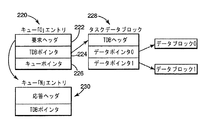
図6は、タスクオペレーションを処理するために、タスクプロセッサ134およびタスクプロセッサ174によって使用されるデータ構造の一例示的実施形態を示したものである。他の適切なデータ構造については、本出願を読めば、当分野の技術者には明らかになるであろう。一例示的実施形態では、要求元プロセッサが、タスク記述ブロック(TDB)をメモリ120に書き込んでいる。タスク記述ブロックには、コマンドコードおよび要求を処理するために必要なコマンド専用情報(ブロックアドレス、ブロックサイズ、データパターン、パリティ係数に対するポインタ等)が含まれている。要求元プロセッサは、次に、タスクプロセッサ134に対して局部的に、要求エントリを要求キュー(例えば、220で示されるキュー「0」)に挿入する。このエントリには、コマンドコード要求ヘッダ222、関連するタスク記述ブロックに対するTDBポインタ224、およびキューポインタ226で示される、応答のためのキュー番号が含まれている。
【0043】
キュー「0」220信号が、空ではない信号を送ると、タスクプロセッサは、キュー220から要求エントリを読み出す。タスクプロセッサは、要求情報を用いてタスクデータブロック228を読み出し、読み出したタスクデータブロック228が要求と一致していることを確認する。次に、タスクプロセッサは、所望の機能を実行する。タスクプロセッサは、完了応答エントリを、230で示される指定応答キューに置き、応答キュー230を通して要求元プロセッサ124に完了通知される。
【0044】
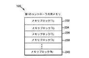
図7は、タスクプロセッサ134による処理に適したメモリブロックに分割された第1のメモリ120に含まれるメモリイメージの一例示的実施形態を示したものである。詳細には、タスクプロセッサ134によって処理されるバックグラウンドタスクは、特定のタスクプロセッサ134を備えるメモリコントローラ122の内部にバッファリングするには大き過ぎる、メモリ120に格納されているデータブロックに対して働くことができる。したがってタスクプロセッサ134は、メモリイメージすなわちブロックを、タスクプロセッサによって処理することができるサイズに対応するメモリブロックすなわちチャンク中に構成するように動作する。図に示す例示的実施形態では、第1のメモリ120に格納されているメモリイメージは、メモリブロック「1」232、メモリブロック「2」234、メモリブロック「3」236、メモリブロック「4」238ないしメモリブロック「N」240中に構成される。一態様では、各チャンクは最大512バイトであり、メモリコントローラ122の内部に内部バッファリングするには十分に小さく、かつ、タスク処理システムを有効に使用するには十分な大きさである。一態様では、タスクプロセッサ134は、メモリコントローラ122の制限内で動作しつつ、メモリイメージ当たりのメモリブロック数が最小になるメモリブロックサイズを構成するように動作している。最大使用可能メモリブロックが512バイトである一態様では、タスクプロセッサ134は、ブロック中にメモリイメージを構成し、第1のメモリブロックおよび最後のメモリブロックのみ、最大すなわち512バイト未満にすることができる。図に示す例示的実施形態では、メモリブロック「1」232およびメモリブロック「N」240を、最大メモリブロックサイズ未満にすることができる。メモリブロック「2」234、メモリブロック「3」236、およびメモリブロック「4」238等は、最大メモリブロックサイズ(例えば512バイト)にすることができる。
【0045】
タスクプロセッサ134およびシステムオペレーションプロセッサ124は、いずれもメモリ120に格納されているデータに対して動作する。冗長コントローラシステム110は、冗長コントローラシステムへの第2のコントローラの追加を含め、タスクプロセッサ134を介してタスクが処理されている間、システムコマンドの処理を継続することができるように構成されることが望ましい。したがって優先順位は、タスクプロセッサ134と他のシステムオペレーションとの間で割り振られるが、これにはメモリ120にアクセスするためのプロセッサ124を介して達成されるものなどが挙げられる。好ましい一実施形態では、タスクプロセッサ134に割り当てられている優先順位は、オペレーティングシステムの性能が、タスクプロセッサ134を介したバックグラウンドタスクの動作によって極端に低下しないように、プロセッサ124よりも低い優先順位(例えば、最下位の優先順位)になっている。別法としては、タスクプロセッサ134のメモリアクセス優先順位を、他のシステムオペレーションと同じか、あるいはそれより高くすることができる。あるいは、ファームウェアを利用して、タスクプロセッサ134を介して達成される個々のタスクのメモリアクセス優先順位を高くすることができる。
【0046】
図8ないし図10は、システムの中断を最小にする、本発明による冗長コントローラシステムへのコントローラのオンライン「ホット」挿入の一例示的実施形態を示したもので、ここでも、本明細書において既に説明した図1ないし図7が参照されている。
【0047】
図8に、本発明による冗長コントローラシステムにコントローラをホット挿入する方法の一例示的実施形態を示す図が、一括して250で示されている。この例示的実施形態では、冗長コントローラシステムは、第1のコントローラ112を介して動作しており、第2のコントローラは、冗長コントローラシステムから除去されている。252で、冗長コントローラシステム110は、単一コントローラシステムとして、第1のコントローラ112を介して動作する。254で、第1のコントローラ112が、冗長コントローラシステム110に第2のコントローラ114が追加されたことを検出する。冗長コントローラシステム110に第2のコントローラ114が追加されたことを検出した後、第1のコントローラ112は、単一コントローラシステムとしての動作を継続する。第1のコントローラは、冗長コントローラシステム110に第2のコントローラ114が追加されたことを示す検出信号を受け取る。一態様では、冗長コントローラシステム110に第2のコントローラ114がホット挿入される場合、ホット挿入されるコントローラは、コントローラが完全に挿入され、所定の位置にラッチされるまで、リセット状態に保持される。存在検出ラインが、新しいコントローラの装着を検出し、挿入されたコントローラ114の存在が、存在検出ライン204を介して第1のコントローラ112に通信される。
【0048】
256で、第2のコントローラ114に電源が投入され、所定の位置へのラッチ待ち状態になり、次に、プロセッササブシステムの自己診断が実行される。プロセッササブシステムの自己診断には、フラッシュROMに存在しているプロセッササブシステムのファームウェアイメージのテスト、およびマイクロプロセッサローカルメモリのテストが含まれており、周辺チップレジスタおよびデータ経路のテストが実行される。258で、第1のコントローラ112および第2のコントローラ114が、交互通信経路202を介して通信する。第2のコントローラ114が冗長コントローラシステム110の一部として未だ「オンライン」になっていない状態であっても、第1のコントローラ112および第2のコントローラ114は、交互通信経路202、メモリ/通信モジュール138、およびメモリ/通信モジュール178を介して、相互に通信する。交互通信経路202を介した、第1のコントローラ112と第2のコントローラ114の間のサンプル通信には、コントローラ間の互換性を確認するためのハードウェアおよびファームウェアのレビジョン情報の交換、テストの結果が出てテストが完了した時の通知、及びホット挿入プロセス中におけるコントローラ間の同期点の通信が含まれている。
【0049】
260で、第2のコントローラ114が、その共用メモリに対する自己診断の実行を含む自己診断を継続する。本明細書において既に説明したように、これらのテストを、バックグラウンドタスクとしてタスクプロセッサ174を介して、システムを中断させることなく実行することができる。262で、すべてのテストに合格しない場合、リカバリモード264に入る。リカバリモード264には、冗長コントローラシステムおよび/またはホストへのエラー状態の提供が含まれている。一実施形態では、コントローラに不良のマークが施され、オフラインに維持される。もう一方のコントローラに対して、上記プロセスが繰り返される。すべてのテストに合格した場合は、266で、第2のコントローラ114が、第1のコントローラ112にメッセージを送り、冗長コントローラシステム110に追加されるべく準備が整ったことを知らせる。
【0050】
図9に、本発明による冗長コントローラシステムにコントローラをホット挿入する方法をさらに示す図が、一括して220で示されている。272で、第1のコントローラ112は、メモリ120を共用書込みおよびローカル読出し専用として位置づける。したがって、その時点以降、メモリ120に書き込まれるデータはすべて、同時に第2のコントローラ114のメモリ160にミラーすなわち書き込まれる。この時点では、メモリ160のメモリイメージは、メモリ120のメモリイメージの「ミラー」コピーではないため、冗長コントローラシステム110の一部として、メモリ120から読み出すことができるのはデータのみである。274で、第1のコントローラ112の許可が出るまで(例えば、交互通信経路202を介して)、第2のコントローラ114による共用メモリ120および独自のメモリ160への書込みが禁止される。
【0051】
276で、第1のコントローラ112が、バックグラウンドタスクを介して、その共用メモリ120のすべてを、共用メモリ120の同一ロケーションにコピーバックする。詳細にはタスクプロセッサ134はバックグラウンドタスクを含んでいるが、ここでタスクプロセッサ134は、メモリ120からメモリブロックを読み出し、読み出したメモリブロックをバッファに格納し、そしてメモリ120の同一ロケーションに書き込んでいる。第1のコントローラ112は、共用書込みモードに構成されているため、上記オペレーションの結果、第1のコントローラ112は、メモリブロック120からメモリブロックをローカルに読み出すことになるが、第1のコントローラ112が、メモリ120の同一ロケーションにライトバックする場合、同時に第2のコントローラ114のメモリ160の同一ロケーションに書き込むことになる。278で、上記バックグラウンドタスクの間、第1のコントローラ112は、プロセッサ124を介してシステムオペレーションコマンドを実行する動作状態を継続する。一態様では、メモリイメージは、一度に1つのメモリブロックがコピーされる。バックグラウンドタスク完了後、ここで第1のメモリ120のメモリイメージは第2のメモリ160のメモリイメージのミラーであり、冗長コントローラシステム110への第2のコントローラ114の追加プロセスが、280で示す通り継続される。
【0052】
図10は、本発明による冗長コントローラシステムへのコントローラの追加方法の一例示的実施形態を示したものであり、290で示す通り、第1のコントローラ112のメモリイメージが第2のコントローラメモリ160のメモリにミラーされた後又はコピーされた後のものである。292で、第1のコントローラ112が再構成され、ミラー書込みおよびミラー読出しモードに構成される。ここで第1のメモリ120および第2のメモリ160の両メモリに対して、データロケーションの読み出し及び書き込みが可能となる。294で、第1のコントローラ112がすべてのメモリロケーションを読み出し、タスクプロセッサ134を介したバックグラウンドタスクを用いて、第1のコントローラの共用メモリ120と第2のコントローラの共用メモリ160の一致性が比較される。したがって、この時点でシステムオペレーションコマンドが中断されることはない。
【0053】
296で、メモリが一致しない場合、リカバリモード298に入る。メモリが一致した場合は、300で、第1のコントローラ112および第2のコントローラ114が再構成され、第2のコントローラが冗長コントローラシステム110に追加される。この時点で冗長コントローラシステム110は、ミラーメモリ冗長コントローラシステムとして完全な動作状態になり、また、第2のコントローラは、ホストをタイムアウトさせることなく、システムオペレーションの処理を最短時間だけ中断させるだけで、冗長コントローラシステムにホット挿入される。
【0054】
コントローラのリセット
知られている二重コントローラシステムでは、一方のコントローラがリセットされると、もう一方のコントローラのマイクロプロセッサへの割込みが生じる。その場合、割り込まれた側のコントローラのプロセッサは、割込みおよびリセットの原因を処理しなければならない。この過去の方法には多くの欠点が知られている。第1のコントローラと第2のコントローラの間のリセットのタイミングは様々である。一方のコントローラが「リセットループ」に入ると、そのリセットは他のコントローラのプロセッサに割込みをかけるが、ここでコントローラシステムの性能に影響を及ぼす拡散動作を備え、洗練度の劣る、ミラリングインタフェースの状態変化に連動する。第2のコントローラが、「スタック」すなわちエラティックプロセッサを有している場合、第2のコントローラのプロセッサは、割込みを処理するためには役に立たないため、第1のコントローラにより、第2のコントローラをリセットさせることはできない。したがって第1のコントローラは、システムを復旧させるためには、リセットを発生する「ウォッチドッグ」モードに頼らざるを得ない。第2のコントローラが、システムを使用して格納されているデータを損傷させる原因となるためには、はるかに長い適期が存在している。
【0055】
図11および図12は、本発明による冗長コントローラシステムを使用してコントローラリセットを処理するシステムおよび方法の一例示的実施形態を示したものである。本発明による冗長コントローラシステムを使用したコントローラリセット処理方法により、ミラリングバスが使用可能状態になった場合に、リセットのみが第2のコントローラに伝播することができるように、一方のコントローラに対するリセットがローカライズされる。このローカライズにより、故障したコントローラが他のすべてのコントローラをリセット状態に保留することを回避している。図11および図12も、本明細書において既に説明した図1ないし図10が参照されている。
【0056】
図11に、本発明による多重冗長コントローラシステムにおけるコントローラリセット処理方法の一例示的実施形態が400で示されている。冗長コントローラシステムは、アクティブに接続されミラー対として動作する、第1のコントローラ112および第2のコントローラ114を備えており、402で、第2のコントローラ114に対するリセット状態が検出される。第2のコントローラ114はリセットされ、シャットダウンプロセスが開始される。404で、シャットダウンプロセスの一環として、第1のコントローラ112と第2のコントローラ114の間の通信リンクを介して、第1のコントローラ112に、コントローラがリセットされたことが通知される。好ましい一実施形態では、ミラーバス200を介して、第1のコントローラ112に、第2のコントローラがリセットされていることが通知される。406で、第1のコントローラ112および第2のコントローラ114の両コントローラに対して、シャットダウンプロセスが実行される。したがって第1のコントローラ112および第2のコントローラ114は、同時にシャットダウンプロセスを通過する。
【0057】
図12に、本発明による二重コントローラシステムにおけるコントローラリセット方法の一例示的実施形態をさらに示す図が410で示されている。412で、両コントローラに対するシャットダウンプロセスが完了すると、第1のコントローラ112および第2のコントローラ114に電源が投入される。シャットダウンプロセスにより、すべての内部バッファがフラッシュされ、メモリが置かれる。414で、シャットダウンプロセスの一部として、第1のコントローラおよび第2のコントローラがリセットされる。416で、第1のコントローラ112と第2のコントローラ114の間のミラーバス200インタフェースの使用が禁止される。一態様では、リセットの作用により、第1のコントローラ112および第2のコントローラ114が、ミラーバス200の使用を禁止している。ミラーバスの使用を禁止する動作により、ミラーバスが再び使用可能になるまで、ボード間でのさらなるリセットの伝播を防止している。
【0058】
418で、第1のコントローラ112および第2のコントローラ114の各々が、自己診断を実行する。通常、自己診断には、内部メモリコントローラASIC122および162のテスト、およびすべてのデータ経路バスのテスト以外に、本出願において既に説明したように、マイクロプロセッササブシステムおよびSDRAMメモリのテストが含まれている。
【0059】
この時点では、第1のコントローラ112と第2のコントローラ114の間のミラーバス200インタフェースは、使用禁止の状態が維持されている。したがってコントローラの一方によって生じる、あるいは自己診断の結果として生じるあらゆるリセットまたは割込みによって、もう一方のコントローラが影響されることはない。420で、自己診断に合格しなかった場合、自己診断が不合格となったコントローラは、422のリカバリモードに入る。通常リカバリモードには、ホストコンピュータシステムに対するエラーの発生、故障の通知、及びアレイ中の「不良」コントローラが使用禁止されないよう除去することが含まれている。残った「正常」コントローラは、データのミラーが必要ない単一コントローラモードで動作を開始する。
【0060】
第1のコントローラ112および第2のコントローラ114の自己診断に合格すると、424で、第1のコントローラ112と第2のコントローラ114の間のミラーバス200インタフェースが使用可能になる。したがって第1のコントローラ112および第2のコントローラ114は、リセットまたはリセットの原因が除去されたことを確認し、ミラー対としての動作を、再び継続することができる。
【0061】
本発明による冗長コントローラシステムを使用した上述のコントローラリセット処理方法によると、ミラーバスと共に使用可能状態にされない限りリセットが第2のコントローラに伝播できないように、1つのコントローラに対するリセットをローカライズする。このローカライズにより、1つのコントローラに、システム内の他のすべてのコントローラをリセットさせることのないシステムファームウェアのための方法が可能となる一方で、多重コントローラボード間のリセットの同期化を、ハードウェアで管理する利点がもたらされる。
【0062】
コントローラの除去
冗長コントローラデータ格納システムからオンラインコントローラを除去する場合、コントローラが「部分除去」されるかあるいは正しく除去されない場合、故障時間が発生することになる。これは、通常、コントローラがオンライン除去されている間、冗長コントローラが静止状態になるか、あるいはリセット状態に保持されることによって生じる。
【0063】
冗長コントローラシステムからコントローラをオンライン除去するための知られているプロセスには早期警告スイッチすなわち短コネクタピンが含まれており、これはコントローラが除去されていることを冗長コントローラシステムに警告するものである。この警告により、コントローラはその時点のコントローラのメモリアクセスを終了させ、コントローラの不揮発メモリを自己リフレッシュモードにすることができる。
【0064】
コントローラが完全に分離(例えば、長コントローラ検出ピンが開放)されると、「対になっている」コントローラのもう一方のコントローラが、冗長コントローラシステムを制御するための動作を再開することができる。検出ピンコネクタを利用しているシステムの場合、部分除去されるコントローラは検出ピンが完全に接点をシャットダウンするまでの間、システムを使用不可の状態に保持することができる。このセットアップでは、例えばコントローラが冗長コントローラシステムから「部分的にのみ除去」される等の誤った手順により、オンライン除去故障時間が延長し、ホストオペレーティングシステムのタイムアウト期間を超過するという場合がある。
【0065】
図13は、本発明による冗長コントローラシステムからコントローラをオンライン除去する方法の一例示的実施形態を示したものである。上記方法は450で示されている。オンライン除去方法450により、冗長コントローラシステムの故障時間を最短にする一方で、コントローラを冗長コントローラシステムから安全にオンライン除去することができる。
【0066】
452で、冗長コントローラシステム110からコントローラが除去されていることが検出される。ここでも、本明細書において既に説明した図1から図12を参照する。一態様では、コネクタ上の早期警告スイッチ又は短コネクタピンが、コントローラが除去されていることをシステム110に警告するが、検出は冗長コントローラシステム110からコントローラが完全に開放される前になされることが好ましい。上記警告は、ホットプラグ警告142またはホットプラグ警告182を介して受信される。本明細書で説明する一例示的実施形態では、第1のコントローラ112が冗長コントローラシステム110から除去される。
【0067】
454で、冗長コントローラシステム110から第1のコントローラ112が除去されていることが検出されると、第1のコントローラ112および第2のコントローラ114に対するシャットダウンシーケンスが実行される。一態様では、456で、各コントローラに対するシャットダウンシーケンスでは、コントローラのプロセッサに割込みがかけられ、プロセッサによる稼動中の処理タスクの終了を可能にしている。458で、各コントローラに対するシャットダウンシーケンスではさらに、メモリ120およびメモリ160に対する未処理のメモリアクセスを完了し、内部バッファをフラッシングする。シャットダウンシーケンスの一部として、メモリコントローラ122によって状態語がメモリ120に書き込まれ、また、メモリコントローラ162によって状態語がメモリ160に書き込まれる。
【0068】
好ましい一実施形態では、第1のメモリ120および第2のメモリ160は、自己リフレッシュモードを有しており、さらに好ましくは、バッテリバックアップを備えている。第1のコントローラ112および第2のコントローラ114に対するシャットダウンシーケンスが完了すると、第1のメモリ120および第2のメモリ160が、それぞれ対応する第1のメモリコントローラ122および第2のメモリコントローラ162によって自己リフレッシュモードに置かれる。462で、除去を検出するコントローラーはオフラインに留まり、除去の終了を待つ。そのメモリは、自己リフレッシュモードに留まっている。464で、除去を検出しないコントローラによって、オンラインになるプロセスが直ちに開始される。
【0069】
本明細書で説明する例示的実施形態では、メモリ120に対する自己リフレッシュプロセスが完了すると、除去を検出する第1のコントローラ112がオフラインに留まり、除去の終了を待ち、およびメモリ120が自己リフレッシュモードに留まる(一態様では、メモリは、バッテリでバックアップされたDRAMである)。除去を検出しない第2のコントローラ114は、直ちにオンラインになるプロセスを開始し、冗長コントローラシステムの故障時間を最短にする。メモリ160(例えばバッテリバックアップDRAM)は、自己リフレッシュモードを解除され、メモリコントローラが使用する、予め書き込まれている状態語を保持している。
【0070】
以上、好ましい実施形態について説明するために、本明細書において特定の実施形態を示し、かつ、記述したが、本発明の範囲を逸脱することなく、広範囲の様々な代替実施態様および/または等価実施態様を、上に示し、かつ、説明した特定の実施形態と置き換えることができることは、当分野の技術者には理解されよう。本発明を、極めて広範囲の様々な実施形態の中で実施することができることは、化学、機械、電気機械、電気、およびコンピュータ技術の分野の技術者には、容易に理解されよう。本出願は、本明細書において説明した好ましい実施形態のあらゆる応用、すなわち変形形態を包含することを意図している。したがって本発明は、特許請求の範囲の各クレームおよびその相当によってのみ制限されることを、明確に意図している。
【0071】
(1)第1のコントローラ(32、112)および第2のコントローラ(34、114)を有する冗長コントローラシステム(30、110)からコントローラをオンライン除去する方法であって、
早期警告検出を介して、前記冗長コントローラシステムからの前記第1のコントローラの部分除去を検出するステップ(452)と、
前記第1のコントローラおよび前記第2のコントローラに対して、未処理のメモリアクセスを完了させるステップ(458)を含むシャットダウンシーケンスを実行するステップ(454)と、
第1のメモリ(50、120)を有するように前記第1のコントローラを定義し、かつ、前記第1のメモリを自己リフレッシュモードにするステップ(460)と、
前記冗長コントローラシステムからの前記第1のコントローラの除去を終了させるステップとを含む方法。
【0072】
(2)第1のプロセッサ(54、124)を含むように前記第1のコントローラを定義するステップと、第2のプロセッサを含むように前記第2のコントローラを定義するステップとを含み、前記第1のコントローラおよび前記第2のコントローラに対してシャットダウンシーケンスを実行する前記ステップ(454)が、前記第1のプロセッサに割り込むステップおよび前記第2のプロセッサに割り込むステップ(456)をさらに含む、(1)に記載の方法。
【0073】
(3)前記第1のプロセッサに割り込む前記ステップが、前記第1のプロセッサによる未処理のプロセッサタスクの終了を可能にするステップを含み、かつ、前記第2のプロセッサに割り込む前記ステップが、前記第2のプロセッサによる未処理のプロセッサタスクの終了を可能にするステップ(456)を含む、(3)に記載の方法。
【0074】
(4)前記第1のメモリを前記自己リフレッシュモードにする前記ステップ(460)が、前記第1のメモリを、メモリの内容を維持するためのメモリコントローラからの外部リフレッシュサイクルを必要としないモードにするステップを含む、(1)に記載の方法。
【0075】
(5)第2のメモリを備えるように前記第2のコントローラを定義し、かつ、前記第2のメモリを自己リフレッシュモードにするステップ(460)を含む、(1)に記載の方法。
【0076】
(6)前記第2のメモリを自己リフレッシュプロセスに置く前記ステップ(460)が、前記第2のメモリを、メモリの内容を維持するためのメモリコントローラからの外部リフレッシュサイクルを必要としないモードにするステップを含む、(5)に記載の方法。
【0077】
(7)前記第2のメモリの自己リフレッシュモードを終了させた後で、前記第2のコントローラに、オンラインになるプロセスを開始させるステップ(464)を含む、(5)に記載の方法。
【0078】
(8)前記オンラインになるプロセスが、前記自己リフレッシュモードを終了させた後で、かつ、前記冗長コントローラシステムからの前記第1のコントローラの除去を終了させる前に、直ちに開始されるように構成される(464)、(7)に記載の方法。
【0079】
(9)第1のプロセッサ(54、124)を含むように前記第1のコントローラを定義し、かつ、第2のプロセッサ(60、164)を含むように前記第2のコントローラを定義するステップと、
前記第1のコントローラおよび前記第2のコントローラに対して、前記第1のプロセッサおよび前記第2のプロセッサに割り込み、前記第1のコントローラおよび前記第2のコントローラに対する未処理のメモリアクセスを完了させるステップ(456)を含むシャットダウンシーケンスを実行するステップ(454)と、
前記第1のメモリの自己リフレッシュモードを解除した後、前記冗長コントローラシステムからの前記第1のコントローラの除去を終了させるステップとを含む、(1)に記載の方法。
【0080】
(10)(1)から(9)に記載の方法を実行するように構成された冗長コントローラシステム(30、110)。
【図面の簡単な説明】
【図1】冗長コントローラをホット挿入するために構成された、本発明による冗長コントローラデータ格納システムの一例示的実施形態を示す図である。
【図2】本発明による冗長コントローラデータ格納システムにコントローラをホット挿入するための方法の一例示的実施形態を示す図である。
【図3】本発明による冗長コントローラシステムにコントローラをホット挿入する方法の他の例示的実施形態を示す図である。
【図4】本発明による冗長コントローラをホット挿入するために構成された冗長コントローラデータ格納システムの他の例示的実施形態を示す構成図である。
【図5】本発明による冗長コントローラデータ格納システムに使用されるタスクプロセッサの一例示的実施形態を示す図である。
【図6】本発明による冗長コントローラシステムのタスクプロセッサによって利用されるデータ構造の一例示的実施形態を示す図である。
【図7】本発明による冗長コントローラデータ格納システムに使用される、メモリブロック中に構成されたメモリイメージを有するコントローラ共用メモリの一例示的実施形態を示す図である。
【図8】本発明による冗長コントローラシステムにコントローラをホット挿入する方法の一例示的実施形態を示す図である。
【図9】本発明による冗長コントローラシステムにコントローラをホット挿入する方法の一例示的実施形態をさらに示す図である。
【図10】本発明による冗長コントローラシステムにコントローラをホット挿入する方法の一例示的実施形態をさらに示す図である。
【図11】本発明による冗長コントローラシステムにおけるコントローラリセット処理方法の一例示的実施形態を示す図である。
【図12】本発明による冗長コントローラシステムにおけるコントローラリセット処理方法の一例示的実施形態をさらに示す図である。
【図13】本発明による冗長コントローラシステムからコントローラを除去する方法の一例示的実施形態を示す図である。
【符号の説明】
32、112 第1のコントローラ
30、110 冗長コントローラシステム
34、114 第2のコントローラ
50、120 第1のメモリ
54、124 第1のプロセッサ
60、164 第2のプロセッサ[0001]
BACKGROUND OF THE INVENTION
The present invention relates generally to redundant controller systems and data storage systems using redundant controllers, and more particularly to redundant controller data storage systems and methods having an online controller removal system.
[0002]
[Prior art]
Multiple controller systems are used to provide a highly reliable redundant data storage system. For example, in the hard disk drive industry, a multiple controller system is one of the RAID (short for redundant array of independent disks) systems that use a combination of multiple disk drives to improve disk drive fault tolerance and disk drive performance. Used as a part. In operation, the RAID system provides redundancy by using multiple controllers. The multiplex controller stripes user data between a plurality of hard disks. The redundant array can be operated from any controller. If there are multiple controllers, using them increases performance and / or increases the number of connection ports in the host computer system. When accessing data, a multi-controller RAID system allows all hard disks to operate simultaneously, greatly improving speed and reliability.
[0003]
The configuration of a RAID system is defined by various RAID levels. Its various RAID level ranges provide data striping (distributing and storing the data blocks of each file across multiple hard disks) and improve disk drive speed and performance without redundancy. It starts with.
[0004]
RAID LEVEL 5 divides data into blocks and stripes them across disk drives. Parity blocks are calculated from the data blocks and stored on the disk. All data blocks and parity blocks are stored (striped) on different disks. If any one of the disk drives fails, only one of the data blocks or parity blocks is lost. In that case, the redundant array can mathematically recreate the lost block. RAID 5 also circulates the disk where data blocks and parity blocks are stored (ie, all disks store several parity blocks on that disk). RAID LEVEL 6 takes the above steps further and calculates two “parity” blocks using different mathematical equations. This allows the redundant array to tolerate two failed disk drives and regenerate all data.
[0005]
Known multiple controller systems include a mirror dual controller data storage system. Each controller includes its own memory, most of which is a “mirror image” or “memory image” that is the same as other memories. By using mirror memory with a dual controller, if one of the controllers or its memory is damaged or lost, it can be quickly recovered and data loss can be prevented. Without a mirror copy of the memory, if a controller suddenly fails, important data on that controller will be lost.
[0006]
For example, in a mirror memory dual controller system having controller A and controller B, the memory of controller A becomes a “mirror image” of the memory of controller B by mirror reading and writing. If a loss or controller B fails, all system operations automatically switch to controller A, which runs the entire system.
[0007]
As the number of applications in computer systems increases, a very high level of reliability is required, including extremely large limitations on processor failure time. For example, in known systems, the total failure time of the controller is required to be less than 5 minutes per year. Normally, if a loss or one of the controllers fails, the controller must be replaced immediately to maintain the redundancy and reliability of the associated data storage system. Due to the above requirements, for systems that typically require a high degree of reliability and “ready time”, the controller to be replaced must be inserted online or “hot” while other controllers (eg, , Controller A) must remain operational. The operating system automatically recognizes that the replacement controller has been inserted.
[0008]
Usually, the multiple controller system is connected to a host. Therefore, the host system often requires that the data storage system not be shut down for a considerable length of time or cause the host system to time out by replacing the controller board.
[0009]
Inserting a replacement controller into an operating system often causes loss of system usage until the replacement controller is tested and added in the operating system. When a replacement controller is added as part of a mirrored memory system, the problems increase in connection with adding a replacement controller to a running system.
[0010]
In a known mirrored memory dual controller system, if controller A is hot inserted while controller A is operating in the system, both controller A and replacement controller B are reset and each of the controllers has a processor sub- The system must be self-diagnosed.
[0011]
Each controller tests its own shared memory system to confirm that the hardware is operating normally. Each controller checks the contents of its shared memory to confirm the “validity” of the memory image for the system. In this example, only controller A will have an effective memory image of the system.
[0012]
Each controller then exchanges information about each other's revisions, the latest view of the system, and the system state when the system was last active. After sharing this information, the firmware determines which controller has a valid memory image. In this example, the controller A has an effective memory image. The shared memory image of controller A is copied to controller B and verified, but for this, the processor of controller A must read all shared memory of controller A and write to all shared memory locations of controller B. Don't be.
[0013]
Next, the memory of both controllers is read and compared to verify that the copy operation was successful. If the memory system is large, the above process takes several minutes. Once the final configuration step is performed, the controller is online and fully operational.
[0014]
Many steps of the above process may require tens of seconds to perform. The process of copying and verifying the shared memory image of controller A to controller B may require several minutes. During this extended period of time required for hot insertion, most host computer operating systems will time out.
[0015]
[Problems to be solved by the invention]
It would be desirable to have hot insertion and / or systems and methods for use in redundant mirror memory multiple controller systems that reduce system failure time and do not cause host computer operating system timeouts. It would also be desirable to have an effective controller reset processing method that minimizes system failure time or host timeout.
[0016]
[Means for Solving the Problems]
The present invention relates to a multiple controller system and data storage system using redundant controllers, and more particularly to a redundant controller data storage system and method having an online controller removal system.
[0017]
According to one embodiment of the present invention, a method for online removal of a controller from a redundant controller system is provided. The redundant controller system includes a first controller and a second controller, and the method includes detecting partial removal of the first controller from the redundant controller system. A shutdown sequence including completion of outstanding memory accesses is performed for the first controller and the second controller. The first controller is defined to have a first memory that is placed in a self-refresh mode. The removal of the first controller from the redundant controller system ends after the self-refresh mode set by the first memory is completed.
[0018]
In accordance with another embodiment of the present invention, a method is provided for online removal of a controller from a redundant controller system. The redundant controller system includes a first controller and a second controller. The first controller is defined to comprise a first processor and the second controller is defined to comprise a second processor. A partial removal of the first controller from the redundant controller system is detected. A shutdown sequence including an interrupt to the first processor and an interrupt to a second processor to complete an outstanding memory access of the first controller and the second controller comprises a first controller and a second controller It is executed for the controller. The first controller is defined to have a first memory and is in a self-refresh mode. The removal of the first controller from the redundant controller system ends after the self-refresh mode by the first memory is completed.
[0019]
In accordance with another embodiment of the present invention, a redundant controller system configured for online removal of redundant controllers is provided. The system comprises a first controller including a first memory, a first processor, and a system for early detection of partial removal of the first controller, wherein partial removal of the first controller is detected. Then, the first controller executes a shutdown sequence including completion of a memory access that has not been processed for the first memory. The second controller includes a second memory and a second processor, and when a partial removal of the first controller is detected, a memory access that has not been processed for the first memory. Perform shutdown mode including completion of. When the shutdown sequence by the first controller and the second controller is completed, the second memory is placed in the self-refresh mode, and the removal of the first controller from the redundant controller system is completed.
[0020]
DETAILED DESCRIPTION OF THE INVENTION
Preferred embodiments of the invention are described in detail below with reference to the accompanying drawings, which form a part of this specification and are provided for the purpose of illustrating specific embodiments in which the invention can be practiced. It should be understood that other embodiments may be utilized and structural or logic changes may be made without departing from the scope of the present invention. The following detailed description is, therefore, not to be taken as limiting the invention. The scope of the invention is defined by the claims.
[0021]
FIG. 1 shows generally an exemplary embodiment of a redundant controller data storage system according to the present invention, generally designated 30. The redundant controller data storage system provides redundant controller memory, multiple controller systems with online or "hot" insertion systems, and methods to reduce system failure time and prevent the host computer operating system from timing out during controller replacement is doing. In one aspect of the invention, redundant controller
[0022]
The components according to the present invention can be implemented in hardware via a microprocessor, programmable logic or state machine, and firmware, or can be implemented in software within a given device. In a preferred embodiment, one or more components according to the present invention are present in the software and used via hardware. A component according to the invention can also be present in software on one or more computer-readable media. As used herein, the term computer readable medium refers to any type of volatile memory, such as floppy disk, hard disk, CD-ROM, flash memory, read only memory (ROM), and random access memory (RAM). Or it is defined as including a non-volatile memory. The system according to the present invention may also use a microprocessor embedded system / device that incorporates bespoke device hardware and / or dedicated single purpose hardware.
[0023]
In one exemplary embodiment,
[0024]
The redundant controller data storage system is configured to communicate with the host or control system via the host or
[0025]
In one embodiment, the
[0026]
In a redundant controller
[0027]
The redundant controller
[0028]
In a preferred embodiment,
[0029]
FIG. 2 illustrates an exemplary embodiment of a method for hot inserting a controller into a redundant controller data storage system according to the present invention, indicated collectively at 80. The method includes configuring the first controller to include a first memory, a task processor, and a system operations processor. The first memory includes a first memory image. In the exemplary embodiment shown in the figure, the
[0030]
FIG. 3 illustrates another exemplary embodiment of a method for hot inserting a controller into a redundant controller data storage system according to the present invention, indicated collectively at 90. The method includes configuring the
[0031]
FIG. 4 shows another exemplary embodiment of a redundant controller data storage system according to the present invention, generally indicated at 110. The redundant controller
[0032]
The redundant controller
[0033]
In one aspect, the
[0034]
Similarly, the second
[0035]
The
[0036]
In one embodiment,
[0037]
In one aspect, the
[0038]
In one embodiment, all background tasks or functions performed by
[0039]
In one aspect, mirror reads and mirror writes between the
[0040]
[0041]
FIG. 5 illustrates an exemplary embodiment of a task processor used in a redundant controller system according to the present invention. Although the
[0042]
FIG. 6 illustrates an exemplary embodiment of a data structure used by
[0043]
When the queue “0” 220 signal sends a non-empty signal, the task processor reads the request entry from the
[0044]
FIG. 7 illustrates an exemplary embodiment of a memory image included in the
[0045]
Both the
[0046]
FIGS. 8-10 illustrate one exemplary embodiment of an online “hot” insertion of a controller into a redundant controller system according to the present invention that minimizes system interruptions, which is again described herein. Reference is made to FIGS. 1-7 described above.
[0047]
In FIG. 8, a diagram illustrating one exemplary embodiment of a method for hot inserting a controller into a redundant controller system according to the present invention is shown generally at 250. In this exemplary embodiment, the redundant controller system is operating via the
[0048]
At 256, the
[0049]
At 260, the
[0050]
9, a diagram further illustrating 220 a method for hot inserting a controller into a redundant controller system according to the present invention is shown collectively at 220. At 272, the
[0051]
At 276, the
[0052]
FIG. 10 illustrates one exemplary embodiment of a method for adding a controller to a redundant controller system in accordance with the present invention, where the memory image of the
[0053]
If the memory does not match at 296, the
[0054]
Reset controller
In known dual controller systems, when one controller is reset, an interrupt to the microprocessor of the other controller occurs. In that case, the interrupted controller's processor must handle the cause of the interrupt and reset. Many disadvantages are known for this past method. There are various reset timings between the first controller and the second controller. When one controller enters a "reset loop", the reset interrupts the other controller's processor, but with a diffuse operation that affects the performance of the controller system, a less sophisticated state of the mirroring interface Linked to change. If the second controller has a “stack” or an elastic processor, the second controller's processor is useless to handle the interrupt, so the first controller causes the second controller to It cannot be reset. Thus, the first controller must rely on a “watchdog” mode that generates a reset to restore the system. A much longer time frame exists for the second controller to cause damage to data stored using the system.
[0055]
11 and 12 illustrate one exemplary embodiment of a system and method for handling controller resets using a redundant controller system according to the present invention. The controller reset processing method using the redundant controller system according to the present invention localizes the reset for one controller so that only the reset can be propagated to the second controller when the mirroring bus is enabled. Is done. This localization prevents the failed controller from holding all other controllers in reset. 11 and 12 also refer to FIGS. 1 to 10 already described in this specification.
[0056]
FIG. 11 illustrates at 400 an exemplary embodiment of a controller reset processing method in a multiple redundant controller system according to the present invention. The redundant controller system includes a
[0057]
FIG. 12 illustrates at 410 a diagram further illustrating one exemplary embodiment of a controller reset method in a dual controller system according to the present invention. At 412, when the shutdown process for both controllers is complete, the
[0058]
At 418, each of the
[0059]
At this time, the mirror bus 200 interface between the
[0060]
If the self-diagnosis of the
[0061]
According to the above-described controller reset processing method using the redundant controller system according to the present invention, the reset for one controller is localized so that the reset cannot be propagated to the second controller unless it is enabled with the mirror bus. This localization allows a method for system firmware that does not cause one controller to reset all other controllers in the system, while allowing hardware to synchronize resets between multiple controller boards. Benefits of managing.
[0062]
Remove controller
When removing an online controller from a redundant controller data storage system, failure times will occur if the controller is “partially removed” or not properly removed. This is usually caused by the redundant controller becoming stationary or held in reset while the controller is removed online.
[0063]
Known processes for online removal of a controller from a redundant controller system include an early warning switch or short connector pin that alerts the redundant controller system that the controller has been removed. . By this warning, the controller can terminate the memory access of the controller at that time and put the nonvolatile memory of the controller into the self-refresh mode.
[0064]
When the controller is completely separated (eg, the long controller detect pin is open), the other controller of the “paired” controller can resume operation to control the redundant controller system. For systems that utilize a detection pin connector, the partially removed controller can keep the system disabled until the detection pin completely shuts down the contacts. This setup may extend the online removal failure time and exceed the host operating system timeout period due to an erroneous procedure such as, for example, the controller being “partially removed” from the redundant controller system.
[0065]
FIG. 13 illustrates an exemplary embodiment of a method for online removal of a controller from a redundant controller system according to the present invention. The method is indicated at 450.
[0066]
At 452, it is detected that a controller has been removed from the
[0067]
If it is detected at 454 that the
[0068]
In a preferred embodiment, the
[0069]
In the exemplary embodiment described herein, upon completion of the self-refresh process for
[0070]
While specific embodiments have been shown and described herein to describe preferred embodiments, a wide variety of alternative embodiments and / or equivalent implementations have been described without departing from the scope of the invention. Those skilled in the art will appreciate that aspects may be substituted for the specific embodiments shown and described above. It will be readily appreciated by those skilled in the chemical, mechanical, electromechanical, electrical, and computer arts that the present invention may be implemented in a very wide variety of embodiments. This application is intended to cover any applications or variations of the preferred embodiments described herein. Therefore, it is manifestly intended that this invention be limited only by the claims and the equivalents thereof.
[0071]
(1) A method for online removal of a controller from a redundant controller system (30, 110) having a first controller (32, 112) and a second controller (34, 114) comprising:
Detecting a partial removal of the first controller from the redundant controller system via early warning detection (452);
Performing a shutdown sequence (454) including completing (458) an unprocessed memory access to the first controller and the second controller;
Defining the first controller to have a first memory (50, 120) and placing the first memory in a self-refresh mode (460);
Terminating the removal of the first controller from the redundant controller system.
[0072]
(2) defining the first controller to include a first processor (54, 124) and defining the second controller to include a second processor; The step (454) of executing a shutdown sequence for one controller and the second controller further comprises interrupting the first processor and interrupting the second processor (456). ) Method.
[0073]
(3) The step of interrupting the first processor includes allowing the first processor to terminate an unprocessed processor task, and the step of interrupting the second processor includes the first processor The method of (3), comprising the step (456) of allowing an unprocessed processor task to be terminated by two processors.
[0074]
(4) The step (460) of setting the first memory to the self-refresh mode sets the first memory to a mode that does not require an external refresh cycle from the memory controller for maintaining the contents of the memory. The method according to (1), including the step of:
[0075]
(5) The method of (1), comprising the step of defining (460) the second controller to comprise a second memory and placing the second memory in a self-refresh mode.
[0076]
(6) The step (460) of placing the second memory in a self-refresh process puts the second memory into a mode that does not require an external refresh cycle from the memory controller to maintain the contents of the memory. The method according to (5), comprising a step.
[0077]
(7) The method according to (5), including the step (464) of causing the second controller to start a process to go online after terminating the self-refresh mode of the second memory.
[0078]
(8) The process of going online is configured to start immediately after ending the self-refresh mode and before ending removal of the first controller from the redundant controller system. (464), The method as described in (7).
[0079]
(9) defining the first controller to include a first processor (54, 124) and defining the second controller to include a second processor (60, 164); ,
Interrupting the first controller and the second controller to the first controller and the second controller to complete an unprocessed memory access to the first controller and the second controller; (454) executing a shutdown sequence including (456);
Terminating the removal of the first controller from the redundant controller system after releasing the self-refresh mode of the first memory.
[0080]
(10) A redundant controller system (30, 110) configured to execute the method according to (1) to (9).
[Brief description of the drawings]
FIG. 1 illustrates an exemplary embodiment of a redundant controller data storage system according to the present invention configured for hot insertion of redundant controllers.
FIG. 2 illustrates an exemplary embodiment of a method for hot inserting a controller into a redundant controller data storage system according to the present invention.
FIG. 3 illustrates another exemplary embodiment of a method for hot inserting a controller into a redundant controller system according to the present invention.
FIG. 4 is a block diagram illustrating another exemplary embodiment of a redundant controller data storage system configured for hot insertion of redundant controllers according to the present invention.
FIG. 5 illustrates an exemplary embodiment of a task processor used in a redundant controller data storage system according to the present invention.
FIG. 6 illustrates an exemplary embodiment of a data structure utilized by a task processor of a redundant controller system according to the present invention.
FIG. 7 illustrates an exemplary embodiment of a controller shared memory having a memory image organized in memory blocks for use in a redundant controller data storage system according to the present invention.
FIG. 8 illustrates an exemplary embodiment of a method for hot inserting a controller into a redundant controller system according to the present invention.
FIG. 9 further illustrates an exemplary embodiment of a method for hot insertion of a controller into a redundant controller system according to the present invention.
FIG. 10 further illustrates an exemplary embodiment of a method for hot inserting a controller into a redundant controller system according to the present invention.
FIG. 11 is a diagram illustrating an exemplary embodiment of a controller reset processing method in a redundant controller system according to the present invention.
FIG. 12 is a diagram further illustrating an exemplary embodiment of a controller reset processing method in a redundant controller system according to the present invention;
FIG. 13 illustrates an exemplary embodiment of a method for removing a controller from a redundant controller system according to the present invention.
[Explanation of symbols]
32, 112 first controller
30, 110 Redundant controller system
34, 114 second controller
50, 120 first memory
54, 124 first processor
60, 164 second processor
Claims (8)
早期検出信号に応じて、前記第1のコントローラが、前記冗長コントローラシステムから該第1のコントローラの除去が行われていることを検出するステップであって、該早期検出信号は、前記第1のコントローラの前記システムからの除去が行われている間にわたって発せられる、ステップと、
前記第1のコントローラおよび前記第2のコントローラの両方が、それぞれの前記第1および第2のメモリに対する未処理のメモリアクセスを完了させることを含むシャットダウンシーケンスを実行するステップと、
前記第1のコントローラが、前記第1のメモリを自己リフレッシュモードにすると共に、前記第2のコントローラが、前記第2のメモリを自己リフレッシュモードにするステップと、
前記第1のコントローラが、オフラインに留まって前記冗長コントローラシステムからの前記第1のコントローラの除去が完了するのを待つと共に、前記第2のコントローラが、オンラインになる処理を開始するステップと、
を含む方法。From the redundant controller system having a second controller having a first controller and a second memory having a first memory, a method for removing the controller is online,
Depending on the early detection signal, the first controller from the redundant controller system comprising the steps of: detecting that the removal of the first controller is made, preterm phase detection signal, said first Emitted during removal of the controller from the system ;
Comprising the steps of both the first controller and the second controller performs the shutdown sequence comprising to complete the memory access outstanding for each of said first and second memory,
The first controller placing the first memory in a self-refresh mode, and the second controller placing the second memory in a self-refresh mode ;
The first controller stays offline and waits for the removal of the first controller from the redundant controller system to be completed, and the second controller initiates a process of going online ;
Including methods.
請求項1に記載の方法。 Wherein with the interrupt to the first processor of the first controller in response to early detection signal is applied, the shutdown sequence by the interruption is subjected to a second processor of the second controller is executed,
The method of claim 1.
請求項2に記載の方法。 By interruption it is applied to the first processor, together with untreated processor task is completed by the first processor, by be interrupt Migakake to the second processor, the second processor The unprocessed processor task by is terminated,
The method of claim 2.
請求項1に記載の方法。 To the first memory to the self-refresh mode involves the first memory, the mode that does not require an external refresh cycle from the memory controller to maintain the contents of the memory,
The method of claim 1.
請求項6に記載の方法。Processes that the line, after which end the self-refresh mode of said second memory, configuration prior to removal of the first controller from the redundant controller system is complete, as is immediately started To be
The method of claim 6 .
Applications Claiming Priority (2)
| Application Number | Priority Date | Filing Date | Title |
|---|---|---|---|
| US09/810,103 US6715101B2 (en) | 2001-03-15 | 2001-03-15 | Redundant controller data storage system having an on-line controller removal system and method |
| US09/810,103 | 2001-03-15 |
Publications (3)
| Publication Number | Publication Date |
|---|---|
| JP2002328815A JP2002328815A (en) | 2002-11-15 |
| JP2002328815A5 JP2002328815A5 (en) | 2005-08-11 |
| JP4097436B2 true JP4097436B2 (en) | 2008-06-11 |
Family
ID=25203005
Family Applications (1)
| Application Number | Title | Priority Date | Filing Date |
|---|---|---|---|
| JP2002045800A Expired - Fee Related JP4097436B2 (en) | 2001-03-15 | 2002-02-22 | How to remove a controller online from a redundant controller system |
Country Status (3)
| Country | Link |
|---|---|
| US (1) | US6715101B2 (en) |
| JP (1) | JP4097436B2 (en) |
| GB (1) | GB2375632B (en) |
Families Citing this family (41)
| Publication number | Priority date | Publication date | Assignee | Title |
|---|---|---|---|---|
| US6243829B1 (en) * | 1998-05-27 | 2001-06-05 | Hewlett-Packard Company | Memory controller supporting redundant synchronous memories |
| US6968463B2 (en) | 2001-01-17 | 2005-11-22 | Hewlett-Packard Development Company, L.P. | System for controlling access to resources in a storage area network |
| US6915397B2 (en) * | 2001-06-01 | 2005-07-05 | Hewlett-Packard Development Company, L.P. | System and method for generating point in time storage copy |
| US6931487B2 (en) * | 2001-10-22 | 2005-08-16 | Hewlett-Packard Development Company L.P. | High performance multi-controller processing |
| US7028177B2 (en) * | 2002-01-31 | 2006-04-11 | Hewlett-Packard Development Company, L.P. | Array controller ROM cloning in redundant controllers |
| US7032131B2 (en) * | 2002-03-26 | 2006-04-18 | Hewlett-Packard Development Company, L.P. | System and method for ensuring merge completion in a storage area network |
| US6947981B2 (en) * | 2002-03-26 | 2005-09-20 | Hewlett-Packard Development Company, L.P. | Flexible data replication mechanism |
| US7007042B2 (en) * | 2002-03-28 | 2006-02-28 | Hewlett-Packard Development Company, L.P. | System and method for automatic site failover in a storage area network |
| US7480831B2 (en) * | 2003-01-23 | 2009-01-20 | Dell Products L.P. | Method and apparatus for recovering from a failed I/O controller in an information handling system |
| US7117388B2 (en) * | 2003-04-28 | 2006-10-03 | International Business Machines Corporation | Dynamic, Non-invasive detection of hot-pluggable problem components and re-active re-allocation of system resources from problem components |
| US7209809B2 (en) * | 2003-10-15 | 2007-04-24 | The Boeing Company | Method and apparatus for obtaining high integrity and availability in multi-channel systems |
| US7290170B2 (en) * | 2004-04-07 | 2007-10-30 | International Business Machines Corporation | Arbitration method and system for redundant controllers, with output interlock and automatic switching capabilities |
| TWI306241B (en) * | 2004-07-12 | 2009-02-11 | Infortrend Technology Inc | A controller capable of self-monitoring, a redundant storage system having the same, and its method |
| ITMI20050063A1 (en) | 2005-01-20 | 2006-07-21 | Atmel Corp | METHOD AND SYSTEM FOR THE MANAGEMENT OF A SUSPENSION REQUEST IN A FLASH MEMORY |
| US8127088B2 (en) * | 2005-01-27 | 2012-02-28 | Hewlett-Packard Development Company, L.P. | Intelligent cache management |
| US7301718B2 (en) * | 2005-01-31 | 2007-11-27 | Hewlett-Packard Development Company, L.P. | Recording errors in tape drives |
| US20060230243A1 (en) * | 2005-04-06 | 2006-10-12 | Robert Cochran | Cascaded snapshots |
| US20060294149A1 (en) * | 2005-06-24 | 2006-12-28 | Intel Corporation | Method and apparatus for supporting memory hotplug operations using a dedicated processor core |
| JP4831599B2 (en) | 2005-06-28 | 2011-12-07 | ルネサスエレクトロニクス株式会社 | Processing equipment |
| US7779218B2 (en) * | 2005-07-22 | 2010-08-17 | Hewlett-Packard Development Company, L.P. | Data synchronization management |
| US7206156B2 (en) * | 2005-07-27 | 2007-04-17 | Hewlett-Packard Development Company, L.P. | Tape drive error management |
| US7325078B2 (en) * | 2005-10-06 | 2008-01-29 | Hewlett-Packard Development Company, L.P. | Secure data scrubbing |
| US7721053B2 (en) * | 2005-10-24 | 2010-05-18 | Hewlett-Packard Development Company, L.P. | Intelligent logical unit provisioning |
| US7467268B2 (en) | 2006-04-14 | 2008-12-16 | Hewlett-Packard Development Company, L.P. | Concurrent data restore and background copy operations in storage networks |
| US7430487B2 (en) * | 2006-09-06 | 2008-09-30 | International Business Machines Corporation | System and method for implementing a programmable DMA master with data checking utilizing a drone system controller |
| US7934027B2 (en) * | 2007-01-19 | 2011-04-26 | Hewlett-Packard Development Company, L.P. | Critical resource management |
| US7861031B2 (en) * | 2007-03-01 | 2010-12-28 | Hewlett-Packard Development Company, L.P. | Access control management |
| US8024514B2 (en) * | 2007-03-01 | 2011-09-20 | Hewlett-Packard Development Company, L.P. | Access control management |
| US7694079B2 (en) | 2007-04-04 | 2010-04-06 | Hewlett-Packard Development Company, L.P. | Tagged sequential read operations |
| US8555042B2 (en) * | 2008-05-29 | 2013-10-08 | International Business Machines Corporation | Apparatus, system, and method for resetting and bypassing microcontroller stations |
| US20090300411A1 (en) * | 2008-06-03 | 2009-12-03 | Gerald Keith Bartley | Implementing Redundant Memory Access Using Multiple Controllers for Memory System |
| US20090300291A1 (en) * | 2008-06-03 | 2009-12-03 | Gerald Keith Bartley | Implementing Cache Coherency and Reduced Latency Using Multiple Controllers for Memory System |
| JP5038237B2 (en) * | 2008-06-06 | 2012-10-03 | 株式会社リコー | Electronic device, image forming apparatus, start control method for electronic device, start control program, and recording medium |
| US8166351B2 (en) * | 2008-10-21 | 2012-04-24 | At&T Intellectual Property I, L.P. | Filtering redundant events based on a statistical correlation between events |
| US7936260B2 (en) * | 2008-11-05 | 2011-05-03 | At&T Intellectual Property I, L.P. | Identifying redundant alarms by determining coefficients of correlation between alarm categories |
| US20100146039A1 (en) * | 2008-12-08 | 2010-06-10 | Dell Products L.P. | System and Method for Providing Access to a Shared System Image |
| US8069217B2 (en) * | 2009-04-16 | 2011-11-29 | Dell Products L.P. | System and method for providing access to a shared system image |
| JP5502372B2 (en) * | 2009-06-05 | 2014-05-28 | トヨタ自動車株式会社 | In-vehicle electronic system |
| WO2012131761A1 (en) * | 2011-03-28 | 2012-10-04 | 富士通株式会社 | Information processing system and information processing system processing method |
| US10031820B2 (en) * | 2013-01-17 | 2018-07-24 | Lenovo Enterprise Solutions (Singapore) Pte. Ltd. | Mirroring high performance and high availablity applications across server computers |
| JP6287644B2 (en) * | 2014-07-03 | 2018-03-07 | 日本精工株式会社 | Control device for electric power steering device |
Family Cites Families (42)
| Publication number | Priority date | Publication date | Assignee | Title |
|---|---|---|---|---|
| US5193154A (en) | 1987-07-10 | 1993-03-09 | Hitachi, Ltd. | Buffered peripheral system and method for backing up and retrieving data to and from backup memory device |
| US4958273A (en) | 1987-08-26 | 1990-09-18 | International Business Machines Corporation | Multiprocessor system architecture with high availability |
| US5204952A (en) | 1988-07-18 | 1993-04-20 | Northern Telecom Limited | Duplex processor arrangement for a switching system |
| DE69027491T2 (en) | 1989-08-01 | 1997-02-06 | Digital Equipment Corp | Software error handling procedures |
| JPH03132143A (en) | 1989-10-17 | 1991-06-05 | Fujitsu Ltd | Emergency restart processing system in exchange system |
| US5195100A (en) | 1990-03-02 | 1993-03-16 | Micro Technology, Inc. | Non-volatile memory storage of write operation identifier in data sotrage device |
| US5212785A (en) | 1990-04-06 | 1993-05-18 | Micro Technology, Inc. | Apparatus and method for controlling data flow between a computer and memory devices |
| US5140592A (en) | 1990-03-02 | 1992-08-18 | Sf2 Corporation | Disk array system |
| US5214778A (en) | 1990-04-06 | 1993-05-25 | Micro Technology, Inc. | Resource management in a multiple resource system |
| US5155845A (en) | 1990-06-15 | 1992-10-13 | Storage Technology Corporation | Data storage system for providing redundant copies of data on different disk drives |
| US5212784A (en) | 1990-10-22 | 1993-05-18 | Delphi Data, A Division Of Sparks Industries, Inc. | Automated concurrent data backup system |
| US5155835A (en) | 1990-11-19 | 1992-10-13 | Storage Technology Corporation | Multilevel, hierarchical, dynamically mapped data storage subsystem |
| US5278838A (en) | 1991-06-18 | 1994-01-11 | Ibm Corp. | Recovery from errors in a redundant array of disk drives |
| DE69227956T2 (en) | 1991-07-18 | 1999-06-10 | Tandem Computers Inc | Multiprocessor system with mirrored memory |
| US5237658A (en) | 1991-10-01 | 1993-08-17 | Tandem Computers Incorporated | Linear and orthogonal expansion of array storage in multiprocessor computing systems |
| US5297258A (en) | 1991-11-21 | 1994-03-22 | Ast Research, Inc. | Data logging for hard disk data storage systems |
| US5287462A (en) | 1991-12-20 | 1994-02-15 | Ncr Corporation | Bufferless SCSI to SCSI data transfer scheme for disk array applications |
| US5289418A (en) | 1992-02-14 | 1994-02-22 | Extended Systems, Inc. | Memory apparatus with built-in parity generation |
| US5388254A (en) | 1992-03-27 | 1995-02-07 | International Business Machines Corporation | Method and means for limiting duration of input/output (I/O) requests |
| US5418921A (en) | 1992-05-05 | 1995-05-23 | International Business Machines Corporation | Method and means for fast writing data to LRU cached based DASD arrays under diverse fault tolerant modes |
| US5459857A (en) | 1992-05-15 | 1995-10-17 | Storage Technology Corporation | Fault tolerant disk array data storage subsystem |
| US5379415A (en) | 1992-09-29 | 1995-01-03 | Zitel Corporation | Fault tolerant memory system |
| US5437022A (en) | 1992-12-17 | 1995-07-25 | International Business Machines Corporation | Storage controller having additional cache memory and a means for recovering from failure and reconfiguring a control unit thereof in response thereto |
| US5473770A (en) * | 1993-03-02 | 1995-12-05 | Tandem Computers Incorporated | Fault-tolerant computer system with hidden local memory refresh |
| US5546539A (en) | 1993-12-29 | 1996-08-13 | Intel Corporation | Method and system for updating files of a plurality of storage devices through propogation of files over a nework |
| US5555510A (en) * | 1994-08-02 | 1996-09-10 | Intel Corporation | Automatic computer card insertion and removal algorithm |
| JP3231561B2 (en) * | 1994-09-22 | 2001-11-26 | 日本電気株式会社 | Backup memory control method |
| US5682471A (en) | 1994-10-06 | 1997-10-28 | Billings; Thomas Neal | System for transparently storing inputs to non-volatile storage and automatically re-entering them to reconstruct work if volatile memory is lost |
| US5574863A (en) | 1994-10-25 | 1996-11-12 | Hewlett-Packard Company | System for using mirrored memory as a robust communication path between dual disk storage controllers |
| EP0717358B1 (en) | 1994-12-15 | 2001-10-10 | Hewlett-Packard Company, A Delaware Corporation | Failure detection system for a mirrored memory dual controller disk storage system |
| EP0721162A2 (en) | 1995-01-06 | 1996-07-10 | Hewlett-Packard Company | Mirrored memory dual controller disk storage system |
| US5568641A (en) | 1995-01-18 | 1996-10-22 | Hewlett-Packard Company | Powerfail durable flash EEPROM upgrade |
| US5553230A (en) | 1995-01-18 | 1996-09-03 | Hewlett-Packard Company | Identifying controller pairs in a dual controller disk array |
| US5666512A (en) | 1995-02-10 | 1997-09-09 | Hewlett-Packard Company | Disk array having hot spare resources and methods for using hot spare resources to store user data |
| US6591374B1 (en) * | 1995-12-22 | 2003-07-08 | Cisco Technology, Inc. | Method and apparatus for forcing system components to temporarily enter a standby mode of operation during switching events |
| US5856989A (en) | 1996-08-13 | 1999-01-05 | Hewlett-Packard Company | Method and apparatus for parity block generation |
| US6092168A (en) | 1996-10-25 | 2000-07-18 | Hewlett-Packard Co. | Data storage system and method for deallocating space by writing and detecting a predefined data pattern |
| US5964855A (en) * | 1997-04-07 | 1999-10-12 | International Business Machines Corporation | Method and system for enabling nondisruptive live insertion and removal of feature cards in a computer system |
| US6247079B1 (en) * | 1997-05-13 | 2001-06-12 | Micron Electronics, Inc | Apparatus for computer implemented hot-swap and hot-add |
| US5960451A (en) | 1997-09-16 | 1999-09-28 | Hewlett-Packard Company | System and method for reporting available capacity in a data storage system with variable consumption characteristics |
| US6026458A (en) * | 1997-10-14 | 2000-02-15 | International Business Machines Corporation | System with pluggable adapter card and hot-swap interface controller |
| US6505281B1 (en) * | 1998-06-02 | 2003-01-07 | Raymond C. Sherry | Hard disk drives employing high speed distribution bus |
-
2001
- 2001-03-15 US US09/810,103 patent/US6715101B2/en not_active Expired - Fee Related
-
2002
- 2002-02-22 JP JP2002045800A patent/JP4097436B2/en not_active Expired - Fee Related
- 2002-03-08 GB GB0205556A patent/GB2375632B/en not_active Expired - Fee Related
Also Published As
| Publication number | Publication date |
|---|---|
| JP2002328815A (en) | 2002-11-15 |
| US6715101B2 (en) | 2004-03-30 |
| GB2375632A8 (en) | 2003-05-12 |
| GB2375632B (en) | 2005-03-23 |
| GB2375632A (en) | 2002-11-20 |
| GB0205556D0 (en) | 2002-04-24 |
| US20020133744A1 (en) | 2002-09-19 |
Similar Documents
| Publication | Publication Date | Title |
|---|---|---|
| JP4097436B2 (en) | How to remove a controller online from a redundant controller system | |
| US6802023B2 (en) | Redundant controller data storage system having hot insertion system and method | |
| US6708285B2 (en) | Redundant controller data storage system having system and method for handling controller resets | |
| US7549020B2 (en) | Method and apparatus for raid on memory | |
| JP3732440B2 (en) | Method and apparatus for maintaining consistency of data stored in mirroring devices | |
| JP4275771B2 (en) | Warm swap of mirrored write-back cache module | |
| US5975738A (en) | Method for detecting failure in redundant controllers using a private LUN | |
| JPH04205519A (en) | Writing method of data under restoration | |
| JPH05346866A (en) | System and method for establishing writing data maintenance in redundant array data storage system | |
| TWI773155B (en) | Method and apparatus for performing disk management of all flash array server | |
| JP2000181887A5 (en) | ||
| JP2000181887A (en) | Fault processing method for information processor and storage controller | |
| US7653831B2 (en) | Storage system and data guarantee method | |
| US6938188B1 (en) | Method for verifying functional integrity of computer hardware, particularly data storage devices | |
| JP3748117B2 (en) | Error detection system for mirrored memory | |
| US20060015769A1 (en) | Program, method and apparatus for disk array control | |
| JPH1195933A (en) | Disk array system | |
| JP2001075741A (en) | Disk control system and data maintenance method | |
| WO2021043246A1 (en) | Data reading method and apparatus | |
| JP2007115162A (en) | Double storage method of data | |
| JPH1027070A (en) | Data backup system | |
| JPH11154058A (en) | Disk array device and data maintaining method | |
| JP2001265536A (en) | Data damage testing method for hierarchical storage system | |
| JP6513801B2 (en) | Storage system and control method thereof | |
| KR100363221B1 (en) | A disk array system and method of providing fault tolerance for it |
Legal Events
| Date | Code | Title | Description |
|---|---|---|---|
| A521 | Request for written amendment filed |
Free format text: JAPANESE INTERMEDIATE CODE: A523 Effective date: 20050119 |
|
| A621 | Written request for application examination |
Free format text: JAPANESE INTERMEDIATE CODE: A621 Effective date: 20050119 |
|
| A131 | Notification of reasons for refusal |
Free format text: JAPANESE INTERMEDIATE CODE: A131 Effective date: 20071030 |
|
| A521 | Request for written amendment filed |
Free format text: JAPANESE INTERMEDIATE CODE: A523 Effective date: 20080128 |
|
| TRDD | Decision of grant or rejection written | ||
| A01 | Written decision to grant a patent or to grant a registration (utility model) |
Free format text: JAPANESE INTERMEDIATE CODE: A01 Effective date: 20080304 |
|
| A61 | First payment of annual fees (during grant procedure) |
Free format text: JAPANESE INTERMEDIATE CODE: A61 Effective date: 20080311 |
|
| R150 | Certificate of patent or registration of utility model |
Free format text: JAPANESE INTERMEDIATE CODE: R150 |
|
| FPAY | Renewal fee payment (event date is renewal date of database) |
Free format text: PAYMENT UNTIL: 20110321 Year of fee payment: 3 |
|
| FPAY | Renewal fee payment (event date is renewal date of database) |
Free format text: PAYMENT UNTIL: 20120321 Year of fee payment: 4 |
|
| FPAY | Renewal fee payment (event date is renewal date of database) |
Free format text: PAYMENT UNTIL: 20130321 Year of fee payment: 5 |
|
| FPAY | Renewal fee payment (event date is renewal date of database) |
Free format text: PAYMENT UNTIL: 20130321 Year of fee payment: 5 |
|
| S111 | Request for change of ownership or part of ownership |
Free format text: JAPANESE INTERMEDIATE CODE: R313113 |
|
| FPAY | Renewal fee payment (event date is renewal date of database) |
Free format text: PAYMENT UNTIL: 20130321 Year of fee payment: 5 |
|
| R360 | Written notification for declining of transfer of rights |
Free format text: JAPANESE INTERMEDIATE CODE: R360 |
|
| R360 | Written notification for declining of transfer of rights |
Free format text: JAPANESE INTERMEDIATE CODE: R360 |
|
| R371 | Transfer withdrawn |
Free format text: JAPANESE INTERMEDIATE CODE: R371 |
|
| FPAY | Renewal fee payment (event date is renewal date of database) |
Free format text: PAYMENT UNTIL: 20130321 Year of fee payment: 5 |
|
| S111 | Request for change of ownership or part of ownership |
Free format text: JAPANESE INTERMEDIATE CODE: R313113 |
|
| FPAY | Renewal fee payment (event date is renewal date of database) |
Free format text: PAYMENT UNTIL: 20130321 Year of fee payment: 5 |
|
| R350 | Written notification of registration of transfer |
Free format text: JAPANESE INTERMEDIATE CODE: R350 |
|
| FPAY | Renewal fee payment (event date is renewal date of database) |
Free format text: PAYMENT UNTIL: 20140321 Year of fee payment: 6 |
|
| R250 | Receipt of annual fees |
Free format text: JAPANESE INTERMEDIATE CODE: R250 |
|
| LAPS | Cancellation because of no payment of annual fees |