JP4097111B2 - Image forming method and apparatus - Google Patents
Image forming method and apparatus Download PDFInfo
- Publication number
- JP4097111B2 JP4097111B2 JP32843499A JP32843499A JP4097111B2 JP 4097111 B2 JP4097111 B2 JP 4097111B2 JP 32843499 A JP32843499 A JP 32843499A JP 32843499 A JP32843499 A JP 32843499A JP 4097111 B2 JP4097111 B2 JP 4097111B2
- Authority
- JP
- Japan
- Prior art keywords
- color
- vector
- line width
- density
- ink
- Prior art date
- Legal status (The legal status is an assumption and is not a legal conclusion. Google has not performed a legal analysis and makes no representation as to the accuracy of the status listed.)
- Expired - Fee Related
Links
- 238000000034 method Methods 0.000 title claims description 46
- 239000011159 matrix material Substances 0.000 claims description 108
- 239000013598 vector Substances 0.000 claims description 84
- 238000006243 chemical reaction Methods 0.000 claims description 11
- 239000003086 colorant Substances 0.000 claims description 11
- 239000000976 ink Substances 0.000 description 33
- 238000010586 diagram Methods 0.000 description 20
- 230000008707 rearrangement Effects 0.000 description 10
- 230000008034 disappearance Effects 0.000 description 7
- 238000004458 analytical method Methods 0.000 description 5
- 238000007405 data analysis Methods 0.000 description 4
- 235000019557 luminance Nutrition 0.000 description 4
- 230000000873 masking effect Effects 0.000 description 4
- 230000000295 complement effect Effects 0.000 description 3
- 239000006185 dispersion Substances 0.000 description 3
- 230000002265 prevention Effects 0.000 description 3
- 238000007796 conventional method Methods 0.000 description 1
- 230000000694 effects Effects 0.000 description 1
- 230000001771 impaired effect Effects 0.000 description 1
- 239000004973 liquid crystal related substance Substances 0.000 description 1
- 239000000463 material Substances 0.000 description 1
- 230000009466 transformation Effects 0.000 description 1
- 230000004304 visual acuity Effects 0.000 description 1
Images


Landscapes
- Record Information Processing For Printing (AREA)
- Color, Gradation (AREA)
- Image Processing (AREA)
- Facsimile Image Signal Circuits (AREA)
- Color Image Communication Systems (AREA)
Description
【0001】
【発明の属する技術分野】
この発明は、プリンタ、プロッタ等の画像形成装置に係り、特に、階調を有するカラー画像等の多値画像における画像データの面積階調処理に関するものである。
【0002】
【従来の技術】
従来、2値表現(”0:OFF”、”1:ON”)のみ可能な画像形成装置を用いて濃淡画像を再現したい場合、画像の単位領域内の”1:0N”の割合いを変化させて階調を再現させる面積階調法が使用されている。
【0003】
一般に、シアン、マジェンタ、イエローなどのインク(N色)にてカラー表現しようとした場合、各インクに対してL*Lのマトリクス領域でL*L+1階調が再現でき、カラー表現としては、M種類(M=(L*L+1)**N)となる。(ここに、”*”は乗算、”**”はべき乗を表す演算子である。)周知のとおり、マトリクス領域の一辺の大きさであるL値を大きくすればカラー階調表現の幅が広がる。
【0004】
ベクタデータを解析する画像形成装置においては、普通4*4のマトリクスまたは8*8のマトリクスが主流であるが、最近では、128*128のマトリクスを使用しているものもある。
【0005】
ドット配置のパターンとしては、大別してドット分散型とドット集中型とがある。ドット分散型にはBayer型が含まれ、ドット集中型には渦巻き型、網点型が含まれる。解像力はドット分散型のBayer型の方が優れており、階調のリニアな再現性はドット集中型の渦巻き型、網点型の方が優れているといわれている。本発明を実施した装置では、基本的に、図7に示すようにBayer型のディザ法による8*8のマトリクスを使用し、インクは、シアン、マジェンタ、イエローの3色インクでカラーを表現し、さらに黒インクにて黒およびシェードを表現している。
【0006】
通常、ベクタデータの濃淡を表現するためには、濃度値から図7に示すディザマトリクスに対応させて”0:OFF”、”1:ON”のマスクマトリクスを各インク色毎に生成する。各インク色に対して同じ図7のディザマトリクスに対応させると全インクについて同じピクセルに対してインクが出力されてしまうため、インク色ごとにONドットを1ピクセルずらしたマスクマトリクスを生成する手段が公知として知られており、後述する本発明の実施の形態でも採用している。
【0007】
【発明が解決しようとする課題】
しかしながら、従来の方法では、ベクタデータの線幅が十分太い場合(L*LのLより線幅が太い)には、色の再現性はよいが、線幅が細くなると(Lより小さい)色の再現性が悪くなり、場合によっては異なった色にて印字されてしまう。
【0008】
近年、ホストコンピュータの性能が上がり、多種多様のグラフィック、CAD関係のアプリケーションソフトが開発され、カラー処理等も多様化してきている。ベクタデータを生成するプリンタドライバ、プロッタドライバにてベクタデータ作成時にペンの色および濃度値を生成してプリンタやプロッタにデータ転送をおこなうが、アプリケーション側にて低濃度と細線を設定してしまうとベクタの色変化やベクタの欠落が生じてトラブルがよく生じている。
【0009】
本発明は、このような背景において、ベクタのカラー濃度や線幅の如何にかかわらずベクタデータの色変化の発生を防止することができる、信頼性の高い画像形成方法および装置を提供することを目的とする。
【0010】
【課題を解決するための手段】
本発明による画像形成方法は、N色のインクを用い面積階調法にて各色の濃淡を表現するとともに多色のカラーを表現する画像形成方法であって、ベクタの終始点情報、色情報、線幅情報を含むベクタデータを受けるステップと、前記ベクタデータの色情報に応じて各インク色の濃度値を生成するステップと、前記ベクタの少なくとも線幅を予め定めた値と比較するステップと、前記線幅が予め定めた値以上であれば、各色の色合わせのための補正を前記各インクの濃度値に対して施し、前記線幅が予め定めた値未満であれば、前記色合わせのための補正を省略するステップと、予め用意したディザマトリクスに対して前記各インク色の濃度値を適用し、各インクに対するマスクマトリクスパターンを生成するステップと、前記マスクマトリクスパターンを参照して前記ベクタデータをラスタデータに変換するステップと、該ラスタデータに基づいて前記ベクタの印字を行うステップとを備えたことを特徴とする。
【0011】
このように本発明では、ベクタの線幅が予め定めた値未満である場合には、インクの各色の色合わせのための、インク濃度値に対する補正を省略するようにしたので、微小な線幅のベクタの色味が前記補正によって却って変化してしまうという不具合の発生を防止することができる。
【0012】
さらに、前記線幅が予め定めた値以上であれば、前記マスクマトリクスパターンを生成する前に、前記インクの濃度値に対して、入力濃度値に対する出力濃度値をリニアにするためのγ変換を行い、前記線幅が予め定めた値未満で、かつ、所定の低濃度であれば、前記γ変換を省略するようにしてもよい。
【0013】
また、前記線幅が予め定めた値以上であれば、前記生成されたマスクマトリクスパターンに対して当該色毎にONドットをずらすずらし処理を行い、前記線幅が予め定めた値未満で、かつ、所定の低濃度であれば、前記ずらし処理を省略するようにしてもよい。
【0014】
これらによってもベクタの色味の変化を防止することができる。
【0015】
本発明による画像形成方法では、マスクマトリクスパターンの操作により細線消失防止処理を合わせて行うことが望ましい。
【0016】
本発明による画像形成装置は、上記方法を実施するための装置であり、N色のインクを用い面積階調法にて各色の濃淡を表現するとともに多色のカラーを表現する画像形成装置であって、ベクタの終始点情報、色情報、線幅情報を含むベクタデータを受ける手段と、前記ベクタデータの色情報に応じて各インク色の濃度値を生成する手段と、前記ベクタの少なくとも線幅を予め定めた値と比較する手段と、前記線幅が予め定めた値以上であれば、各色の色合わせのための補正を前記各インクの濃度値に対して施し、前記線幅が予め定めた値未満であれば、前記色合わせのための補正を省略する制御手段と、予め用意したディザマトリクスに対して前記各インク色の濃度値を適用し、各インクに対するマスクマトリクスパターンを生成する手段と、前記マスクマトリクスパターンを参照して前記ベクタデータをラスタデータに変換する手段と、該ラスタデータに基づいて前記ベクタの印字を行う印字手段とを備えたことを特徴とする。
【0017】
【発明の実施の形態】
以下、本発明の実施の形態について、図面を参照して詳細に説明する。
【0018】
図1は本発明の画像形成装置の構成を示すブロック図である。図1中、11は装置全体の動作を制御するCPU、12はCPU11の作業領域およびデータの一時記憶領域として利用されるRAMである。13は画像形成装置を駆動するためのプログラムやデータが書き込まれているROMであり、CPU11により使用される。14は外部のコンピュータ端末装置等(図示せず)と接続するためのインタフェース部であり、これを介してベクタデータなどのプロッタ記述言語データが転送されてくる。15はマンマシンインタフェースのための表示を行うLCD表示装置、16は画像形成装置の各種設定を選択するためのキー操作部である。17は画像形成装置の印字部、18はCPU11と他の各要素とを接続するシステムバスである。
【0019】
図2は、画像形成装置における一般的な入力データ受信から印字までの処理フローを示す。
【0020】
まず、外部から入力データ(ベクタデータ)を受信し(S21)、この受信したデータをプロッタ記述言語のフォーマットにしたがって言語解析(データ解析)を行う(S22)。このデータ解析手段を一般にインタープリタと呼んでいる。データ解析は印字開始データの解析終了まで行われる(S23)。印字開始コマンドを受信して今までのベクタデータをラスタに変換するVRC(Vector-to-Raster Conversion)処理(S24)が行われる。このVRC処理では記録に適した印字データを図1のRAM12に展開するものであり、この展開された印字データが実際の印字動作(S25)で参照されて印字動作が開始される。
【0021】
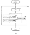
図3は、図2のフロー内のステップS22の言語解析に付随した処理ステップを説明するための図である。
【0022】
解析ステップS31での解析の結果、VRC処理を行うためにベクタの始点・終点座標値(始終点情報)、色情報、線幅情報及びベクタのつなぎ形状や先端形状等を含むベクタデータを図1のRAM12に格納する(即ち登録する)とともに(S34)、ラスタライズを行うためにベクタのカラーパターンを生成し(S32)、図1のRAM12に格納する(S33)。このカラーパターンは、ベクタのラスタライズを行うときに参照されるマスクマトリクスパターンであり、この例では、K、C、M、Yの各色について1面、計4面ある。
【0023】
本発明の実施の形態におけるマスクマトリクスパターン(L*L)のサイズは8*8なのでK、C、M、Yそれぞれ8バイトの容量で図1のRAM12に格納(登録)される。
【0024】
図4は、一般的な図3のベクタカラーパターン生成(S32)の詳細処理フローである。
【0025】
まず、RGBデータの入力を受ける(S41)。RGBデータとは、ディスプレイ等で使われる表色系のことで、パソコンでは通常各色につき0から255までの256階調あり、その組み合わせにより約1600万色の表現が可能である。印刷物の場合、複数のインクの濃度によって表現可能なすべての色をあらわす。赤(R)の補色であるシアン(C)、緑(G)の補色であるマジェンタ(M)、青(B)の補色である黄(Y)のインクを使用する。したがって、C,M,Yの濃度は、次の(1)式に示すように、それぞれR,G,Bの輝度に基づいて求められる。例えば、赤(R)の輝度が大きければシアン(C)の濃度が小さくなる。
【0026】
CMY(濃度)=255−RGB(輝度)・・・(1)式
しかし、ディスプレイ上の輝度と印刷物のインクの濃度との関係は、現実には、(1)式で表されるようなリニアにならない(デバイス特性があるため)。そのために輝度と濃度の関係をリニアにするために、(2)式に示すような対数変換をおこなってリニアにする(S42)。
【0027】
CMY(濃度)=255−(255.0/1.8)*(logRGB/255.0)・・・(2)式
(2)式における定数”1.8”は、本実施の形態における入力デバイスの特性に対応する値である。
【0028】
CMYのインクを同時に打つことで黒(K)が得られるが、CMYを組み合わせて黒を表現するより最初から黒インクを使った方が美しく合理的であり、本実施の形態においても黒インクを含め4つのインクを利用している。CMYの濃度を同じにすると、黒の濃淡であるグレーとなる。そこで、CMYの各濃度の共通部分を黒(インク)の濃度とする(S43)。CMYの濃度のうち最小値をMin(C、M、Y)とすると、これが共通部分であり、(3)式のように黒の濃度となる。黒生成後のCMYの各濃度は、それぞれ(4)〜(6)式のようになる。
【0029】
K=Min(C、M、Y) ・・・(3)式
C=C−Min(C、M、Y)・・・(4)式
M=M−Min(C、M、Y)・・・(5)式
Y=Y−Min(C、M、Y)・・・(6)式
【0030】
次に、インク特性とメディアの特性により理想の色を得るためにマスキングという処理にて色あわせ処理を行う(S44)。通常時の印刷を行う場合は、この色合わせのためのマスキング処理により各色の濃度を補正するために次の(7)式を用いる。
【0031】
【数1】

しかし、細線時の印刷を行う場合は、このマスキング処理を行うと、却って色の再現性が損なわれる。そこで、次の(8)式を用いる。
【0033】
【数2】
この式(8)はKCMYに対して無変換(無補正)であることを示している。
【0035】
このようにして得られたKCMY濃度で2値化処理を行って印刷すると、実際には入力濃度と印刷結果の出力濃度はリニアにならないため、いわゆるγ変換処理を行ってリニアにする(S45)。予め、0から255までの各濃度でインクごとに印刷し、スキャナで濃度を測定し、測定濃度と入力値からγ変換テーブルを作成しておき、γ変換処理時には、このテーブルを参照してγ変換を行う。これらの変換手段を経て、各色毎に2値化処理を行う(S46)。2値化処理は、図7に示すディザマトリクスを利用する。このようにして、各色の濃度について、対応するマスクマトリクスパターンが得られる。例えば、濃度25%の場合、図7のディザマトリクスに基づいて、図8のようなマスクマトリクスパターンが得られる。これが濃度25%における黒のマスクマトリクスとなる。
【0036】
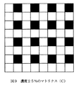
図9、図10、図11は、それぞれ、濃度25%におけるシアン、マジェンタ、イエローのマスクマトリクスを示す図である。これらについては後述する。
【0037】
図5は、本実施の形態における、ベクタカラーパターン生成(S32)の詳細処理フローである。
【0038】
まず、ベクタが細線か否かを判定するため、そのベクタの線幅を所定の判定条件と対比する(S51)。ベクタデータの線幅の判定条件は、Lドット幅で判断するのではなくてLをルート2倍した値で判断するのが望ましい。なぜなら、L*Lのマトリクスにおいて、非0最低濃度のパターンにおけるONドット同士間の最大の間隔がLのルート2倍となるからである。したがって、本実施の形態では、8ドットでなくそのルート2倍の11ドットを判定条件とした。
【0039】
ベクタの線幅および線分長のいずれかが11ドット未満であれば、上記(8)式を利用したカラー値の補正を行い(S53)、両方とも11ドット以上であれば、上記(7)式を利用したカラー値の補正を行う(S52)。前述のように式(8)の補正は、入力カラー値をそのまま出力するので、実際には補正を省略したことに相当する。
【0040】
11ドット未満の場合、ステップS53に続いて、K、C、M、Yの各々について、そのベクタの濃度が低濃度かどうかを判定する(S54)。この具体的な判定方法については後述する。低濃度でなければ、後述するステップS45へ進む。低濃度であれば、各色毎に当該濃度に基づいてディザマトリクスにより2値化処理(S55)を行い、その後、先に生成したカラーパターンについて、細線消失防止処理を施す(S56)。この細線消失防止処理の詳細は、本出願人による特願平10−376673号に開示されている。このようにして得られたカラーパターンはRAM12に登録される(図3、S33)。
【0041】
11ドット以上の場合、ステップS52で生成されたカラーパターンをγ変換(S45)し、各色毎に当該濃度に基づいてディザマトリクスにより2値化(S46)する。これによって得られたカラーパターンをKについてはそのまま用い、C、M、YについてはONドットを順次ずらして(S57)、C、M、Yのカラーパターンを作成し、RAM12に登録する(図3、S33)。この具体的な方法については後述する。
【0042】
前記2値化処理では、より具体的には、まず、出力のK、C、M、Yの各カラーの濃度を図7のディザマトリクスである2値化テーブル(bayerDither_tbl)70にあてがい、それぞれのマスクマトリクスパターンを作成する。2値化テーブル70は、本実施の形態では1個のみ存在し、Kのマスクマトリクスパターンとしては、2値化テーブル70から得られたマスクマトリクスパターンをそのまま利用し、C、M、Y用のマスクマトリクスパターンとしては、2値化テーブル70から得られたマスクマトリクスパターンを順次1bitシフトさせて生成している。このシフトは、ここでの例では、マトリクスの行(ラスタ)単位に右方向にシフトさせている。各行の最右端の値は次の行の先頭へ移動させる。但し、最下行最右端の値は最上行最左端に移動させる。
【0043】
一例として、K、C、M、Yそれぞれが25%濃度出力であった場合のベクタカラーパターン生成(S52)の処理は、図7の2値化テーブル70に25%に対応する数値を適用することにより、マトリクス中の所定のドットがON状態(図では黒で示す)となった図8のマスクマトリクスパターンが生成される。これを、本実施の形態では、Kのインクに利用する。さらに、このパターンを上述の方法で順次1bitシフトした結果がC(図9)、M(図10)、Y(図11)となる。いずれもマトリクス内のONドットの数は同じであり、そのマトリクス内の位置が異なる。
【0044】
(8)式によるベクタカラーパターン生成(S53)の処理では、(7)式で適用したような各色の濃度補正のためのマスキング処理を無効化する。さらに、好ましくは低濃度の場合に、前記細線消失防止処理を施したマスクマトリクスパターンを生成する。また、低濃度の場合にはγ変換およびずらし処理も省略する。このように、本発明では低濃度細線に対しては、各色間の比率を変更するような補正を抑止することにより、当該補正がかえって色の再現性を悪化させるのを防止することができる。
【0045】
本実施の形態では、低濃度か否かの判定条件として、図6に示した条件を採用した。現実には、低濃度でのベクタ全体の欠落には、単に濃度が低いか否かだけでなく、ベクタの傾斜角度も影響するので、ここでは、次の9個の場合に条件を分けている。
【0046】
第1の条件における「線幅1ドットで45度方向」とは、与えられたベクタの始点、終点座標値のx増分の絶対値とy増分の絶対値とが等しいと判断された場合に相当する。このときにベクタの全ドットが抜けてしまうことがない最低濃度のマスクマトリクスパターン(カラーパターン)の濃度は66%である。これより低い濃度ではベクタの全ドットが抜けてしまうことがありうる。したがって、この第1の条件に対する対処として、「濃度66%以下ならカラーパターンの変更」を行うこととしている。なお、実際には濃度66%では問題がないので「濃度66%以下なら」ではなく「濃度66%未満なら」としてもよい(以下も同様)。
【0047】
第2の条件は「線幅が1ドットで45度以外」(すなわち始点、終点座標値のx増分の絶対値とy増分の絶対値が等しくない)と判断された場合である。このときにベクタの全ドットが抜けてしまうことがない最低濃度のマスクマトリクスパターンの濃度は33%である。したがって、この第2の条件に対する対処として、「濃度33%以下ならカラーパターンの変更」を行うこととしている。
【0048】
第3の条件の「線幅2ドットで垂直線以外」とは、線幅が2ドットで、始点、終点座標値のx増分が0でなくかつy増分が0でないと判断された場合である。本明細書では「垂直線」は水平線も含む、角度0度または90度のベクタである。この第3の条件でベクタの全ドットが抜けてしまうことがない最低濃度のマスクマトリクスパターンの濃度は24%である。したがって、この第3の条件に対する対処として、「濃度24%以下ならカラーパターンの変更」を行うこととしている。
【0049】
第4の条件は「線幅が2ドットで垂直線」の場合である。このときにベクタの全ドットが抜けてしまうことがない最低濃度のマスクマトリクスパターンの濃度は8%である。
【0050】
第5の条件は、「線幅3および4ドット」の場合である。このとき、ベクタの全ドットが抜けてしまうことがない最低濃度のマスクマトリクスパターンの濃度は8%である。
【0051】
第6の条件は、「線幅5ドット」の場合である。このときにベクタの全ドットが抜けてしまうことがない最低濃度のマスクマトリクスパターンの濃度は5%である。
【0052】
第7の条件は、「線幅および線分長6,7,8,9ドット」の場合である。このときにベクタの全ドットが抜けてしまうことがない最低濃度のマスクマトリクスパターンの濃度は3%である。
【0053】
第8の条件は、「線幅および線分長10ドット」の場合である。このときにベクタの全ドットが抜けてしまうことがない最低濃度のマスクマトリクスパターンの濃度は2%である。
【0054】
第9の条件は、「線幅および線分長11ドット以上」の場合である。このときは、カラーパターンの変更を必要としないのでその変更は行わない。
【0055】
以上、ベクタの欠落の判断のしかたについて説明したが、次に、細線消失防止のために実際にL*Lマトリクスに基づいて(L*L)*(L*L)マトリクスを作成する方法について説明する。これは、L*Lマトリクスの行(ROW)および列(COLUMN)のL*L−1回配置換え(並び替え)を行って実現する。
【0056】
行と列の並び替えを行うプログラム例(C言語で記載)は下記の通りである。このプログラムの主要部にはその部分の役割を示すコメントを付加してある。但し、このプログラムは行列の配置換えを行うための一例であり、同じ処理が実現できればプログラム言語およびその記述は任意である。
【0057】
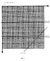
図12は濃度2%未満のマスクマトリクスであり、これをタイリングすると図17のようになる。このマスクマトリクスでは、かなりのベクタが欠落してしまう。図12の8*8のマスクマトリクスに対して前記プログラムの処理を行うことにより64*64のマスクマトリクスを作成した結果を図18に示す。これによって、細線の再現性は図17の場合と比べるとはるかによくなる。
【0059】
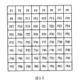
図15のパターンP1は、配置換えの基となる8*8のマスクマトリクスである。P2は、図13で示したように、最上行を最下行へ移動させてP1の行の配置換えをしたものである。P3はP2に対して同様の行の配置換えをしたものである。同様にしてP8まで作成する。P9は、図14で示したように、最右列を最左列に移動させてP1の列の配置換えをしたものである。P10はP2に対して同じ列の配置換えをしたものである。同様にしてP16まで作成する。さらに、次のパターン行であるパターンP17〜P24も同様に直前のパターン行の対応するパターンの配置換えにより作成する。以下の各パターン行についても同様である。
【0060】
このようにして、P1のL*Lのマスクマトリクスに基づいて、図15に示したような(L*L)*(L*L)のマスクマトリクスを作成することができる。前述したように、図12の2%未満の濃度の8*8マスクマトリクスに基づいて同様に作成されたのが図18の64*64マスクマトリクスである。
【0061】
しかし、図18のマスクマトリクスパターンによって、細線の再現性は図17の場合と比べるとはるかによくなるが、図18に示したラインDとラインEのように特定の傾きを有するベクタについてはなおその全体の欠落が生じる。
【0062】
図16は、図18に示したように特定の傾きのベクタについてその全体の欠落が生じることまで考慮した配置換えを説明するための図である。図16のマスクマトリクスは、配置換えにより作成された図15の(L*L)*(L*L)のマスクマトリクスに対してさらに別の行列配置換えを行ったものである。これにより、図18に現れたようなONドットの規則性をなくすことができる。
【0063】
図18におけるONドットの規則性のなくし方について説明する。L*Lのマスクマトリクスを1つの行列要素とするM*Mのマスクマトリクスについて、その配列を変化させることで規則性をなくす。本実施の形態では、まず、M*Mのマスクマトリクスの行について、第8行の内容を第3行に移し、元の第3行の内容を第4行へ移す。同様の元の第4行の内容を第6行へ、元の第6行の内容を第7行へ、元の第8行の内容を第3行へ移す。このようにして、M*Mのマスクマトリクスの行の並べ替えを行う。次に、M*Mのマスクマトリクスに対して、その列について同様の並べ替えを行う。このような操作により、図16のような新たなM*Mのマスクマトリクスが生成される。これは図19の具体例に対応する。図18のマスクマトリクスに比べて、図19のマスクマトリクスはONドットの配置の規則性がなくなっているのが分かる。これによりどのベクタデータの傾きでもベクタの欠落は生じない。規則性のなくし方はこれ以外にも種々考えられるので、どのように行ってもよい。
【0064】
このように、前記プログラムによる図15の配置生成と、M*Mの配列における行および列の並べ替えによるマスクマトリクス生成手段により高精度で各色の濃淡を表現できるようになった。
【0065】
本実施の形態におけるL*Lのマスクマトリクスは8*8なので65階調の濃淡を表現できる。
【0066】
以上の説明では、ベクタのライスタライズの都度、マスクマトリクスを生成するようにしたが、65種類のマスクマトリクスをあらかじめ作成しておくことが可能である。これはテーブル化することができる。図19で示した、(L*L)*(L*L)のマスクマトリクスである64*64のマスクマトリクスの65階調もテーブル化しておくことができる。これらのテーブルを予め図1の不揮発性記憶手段としてのROM13に記憶させておくことによりRAM12の使用量を減らすことができ、さらには、前記プログラムの処理が不要となるため処理速度の向上を図ることができる。
【0067】
【発明の効果】
本発明の画像形成方法および装置によれば、ベクタのカラー濃度や線幅の如何にかかわらずベクタデータの色変化の発生を防止するとともに、濃度に応じて適切な印字を可能とする。また、細線消失防止処理により、細線等が全く印字されないという不具合の発生を防止できる。
【図面の簡単な説明】
【図1】本発明による画像形成装置の構成例を示すブロック図である。
【図2】図1の画像形成装置の入力データ受信から印字までの処理フローを示すフローチャートである。
【図3】図2のフロー内のステップS22の言語解析に付随した処理ステップを説明するための図である。
【図4】一般的なベクタカラーパターン生成の詳細処理フローを示すフローチャートである。
【図5】本発明の実施の形態における、ベクタカラーパターン生成(S32)の詳細処理フローを示すフローチャートである。
【図6】本発明の実施の形態における、ベクタ消失(欠落)が生じるか否かを判定するための判定条件を示した図である。
【図7】本発明の実施の形態における、8*8のBayer型ディザマトリクスを示す図である。
【図8】本発明の実施の形態における、濃度25%における黒のマスクマトリクスを示す図である。
【図9】本発明の実施の形態における、濃度25%におけるシアンのマスクマトリクスを示す図である。
【図10】本発明の実施の形態における、濃度25%におけるマジェンタのマスクマトリクスを示す図である。
【図11】本発明の実施の形態における、濃度25%におけるイエローのマスクマトリクスを示す図である。
【図12】本発明の実施の形態における、濃度2%未満のマスクマトリクスを示す図である。
【図13】パターンP1の最上行を最下行へ移動させてP1の行の配置換えをして得られるパターンP2を示す図である。
【図14】パターンP1の最右列を最左列に移動させてP1の列の配置換えをして得られるパターンP9を示す図である。
【図15】本発明の実施の形態における、配置換えの基となる8*8のマスクマトリクスであるパターンP1を示す図である。
【図16】図18に示したように特定の傾きのベクタについてその全体の欠落が生じることまで考慮した配置換えを説明するための図である。
【図17】図12のマスクマトリクスをタイリングした様子を示す図である。
【図18】図12の8*8のマスクマトリクスに対してプログラムの処理を行うことにより64*64のマスクマトリクスを作成した結果を示す図である。
【図19】図16のような新たなM*Mのマスクマトリクスに対応する具体例を示す図である。
【符号の説明】
11 CPU
12 RAM
13 ROM
14 インターフェース
15 液晶表示装置
16 キー操作部
17 印字部
18 システムバス[0001]
BACKGROUND OF THE INVENTION
The present invention relates to an image forming apparatus such as a printer or a plotter, and more particularly to area gradation processing of image data in a multivalued image such as a color image having gradation.
[0002]
[Prior art]
Conventionally, when it is desired to reproduce a grayscale image using an image forming apparatus capable of only binary expression (“0: OFF”, “1: ON”), the ratio of “1: 0N” in the unit area of the image is changed. The area gradation method is used to reproduce the gradation.
[0003]
In general, when trying to express colors with inks (N colors) of cyan, magenta, yellow, etc., L * L + 1 gradations can be reproduced in the L * L matrix area for each ink. Type (M = (L * L + 1) ** N). (Here, “*” is an operator representing multiplication and “**” is an operator representing power.) As is well known, if the L value, which is the size of one side of the matrix area, is increased, the width of the color gradation expression can be increased. spread.
[0004]
In image forming apparatuses that analyze vector data, a 4 * 4 matrix or an 8 * 8 matrix is usually the mainstream, but recently, there are also some that use a 128 * 128 matrix.
[0005]
The dot arrangement patterns are roughly classified into a dot dispersion type and a dot concentration type. The dot dispersion type includes a Bayer type, and the dot concentration type includes a spiral type and a halftone type. It is said that the dot dispersion type Bayer type is superior in resolving power, and that the linear gradation reproducibility is superior in the dot concentration type spiral type and halftone type. The apparatus embodying the present invention basically uses an 8 * 8 matrix based on the Bayer-type dither method as shown in FIG. 7, and the ink expresses the color with three color inks of cyan, magenta, and yellow. Further, black and shade are expressed by black ink.
[0006]
Usually, in order to express the density of vector data, a mask matrix of “0: OFF” and “1: ON” is generated for each ink color from the density value in correspondence with the dither matrix shown in FIG. If each ink color is made to correspond to the same dither matrix in FIG. 7, ink is output to the same pixel for all inks. Therefore, means for generating a mask matrix in which ON dots are shifted by one pixel for each ink color is provided. It is known as well-known and is also adopted in the embodiments of the present invention described later.
[0007]
[Problems to be solved by the invention]
However, in the conventional method, when the line width of the vector data is sufficiently thick (the line width is larger than L of L * L), the color reproducibility is good, but when the line width is narrow (smaller than L) The reproducibility of the image becomes worse, and in some cases, it is printed in a different color.
[0008]
In recent years, the performance of host computers has improved, and various types of graphics and CAD-related application software have been developed. Color processing and the like have also been diversified. When creating vector data with a printer driver or plotter driver that generates vector data, pen color and density values are generated and transferred to the printer or plotter. If low density and fine lines are set on the application side, Problems often occur due to vector color changes and missing vectors.
[0009]
In such a background, the present invention provides a highly reliable image forming method and apparatus capable of preventing the occurrence of a color change in vector data regardless of the color density or line width of the vector. Objective.
[0010]
[Means for Solving the Problems]
An image forming method according to the present invention is an image forming method that expresses shades of each color using an N-color ink by an area gradation method, and expresses multicolored colors, including vector starting point information, color information, Receiving vector data including line width information; generating a density value of each ink color according to color information of the vector data; comparing at least the line width of the vector with a predetermined value; If the line width is equal to or greater than a predetermined value, correction for color matching of each color is performed on the density value of each ink, and if the line width is less than a predetermined value, the color matching A step of omitting correction for generating a mask matrix pattern for each ink by applying the density value of each ink color to a dither matrix prepared in advance, and the mask matrix Converting said vector data into raster data with reference to the scan pattern, and performing printing of the vector on the basis of the raster data Prepared It is characterized by that.
[0011]
As described above, in the present invention, when the line width of the vector is less than a predetermined value, the correction for the ink density value for color matching of each ink color is omitted. It is possible to prevent the occurrence of a problem that the color tone of the vector changes on the contrary by the correction.
[0012]
Further, if the line width is equal to or greater than a predetermined value, before the mask matrix pattern is generated, γ conversion for linearly changing the output density value relative to the input density value is performed on the ink density value. If the line width is less than a predetermined value and a predetermined low density, the γ conversion may be omitted.
[0013]
If the line width is equal to or greater than a predetermined value, the generated mask matrix pattern is subjected to a shift process for shifting ON dots for each color, and the line width is less than a predetermined value, and If the density is a predetermined low density, the shifting process may be omitted.
[0014]
These also prevent changes in the color of the vector.
[0015]
In the image forming method according to the present invention, it is desirable to perform the thin line disappearance prevention process together by operating the mask matrix pattern.
[0016]
An image forming apparatus according to the present invention is an apparatus for performing the above-described method, and is an image forming apparatus that expresses the shades of each color by an area gradation method using N-color ink and expresses multiple colors. Means for receiving vector data including vector starting point information, color information, and line width information; means for generating a density value of each ink color according to the color information of the vector data; and at least the line width of the vector If the line width is equal to or larger than the predetermined value, correction for color matching of each color is performed on the density value of each ink, and the line width is determined in advance. A control means for omitting correction for color matching, and means for generating a mask matrix pattern for each ink by applying the density value of each ink color to a dither matrix prepared in advance. , Characterized by comprising means for converting the vector data into raster data by referring to the mask matrix pattern, and a printing means for printing of the vector based on the raster data.
[0017]
DETAILED DESCRIPTION OF THE INVENTION
Hereinafter, embodiments of the present invention will be described in detail with reference to the drawings.
[0018]
FIG. 1 is a block diagram showing the configuration of the image forming apparatus of the present invention. In FIG. 1, 11 is a CPU for controlling the operation of the entire apparatus, and 12 is a RAM used as a work area for the
[0019]
FIG. 2 shows a processing flow from reception of general input data to printing in the image forming apparatus.
[0020]
First, input data (vector data) is received from the outside (S21), and the received data is subjected to language analysis (data analysis) according to the format of the plotter description language (S22). This data analysis means is generally called an interpreter. Data analysis is performed until the print start data analysis ends (S23). A VRC (Vector-to-Raster Conversion) process (S24) is performed for receiving the print start command and converting the vector data so far into a raster. In this VRC process, print data suitable for recording is developed in the
[0021]
FIG. 3 is a diagram for explaining processing steps associated with language analysis in step S22 in the flow of FIG.
[0022]
As a result of the analysis in the analysis step S31, vector data including vector start point / end point coordinate values (start / end point information), color information, line width information, vector connection shape, tip shape, etc. for performing VRC processing is shown in FIG. Are stored (i.e., registered) (S34), a vector color pattern is generated for rasterization (S32), and stored in the
[0023]
Since the size of the mask matrix pattern (L * L) in the embodiment of the present invention is 8 * 8, each of K, C, M, and Y is stored (registered) in the
[0024]
FIG. 4 is a detailed processing flow of the vector color pattern generation (S32) in FIG.
[0025]
First, input of RGB data is received (S41). The RGB data is a color system used in a display or the like. In a personal computer, there are usually 256 gradations from 0 to 255 for each color, and about 16 million colors can be expressed by a combination thereof. In the case of printed matter, all colors that can be expressed by the density of a plurality of inks are represented. Cyan (C) that is a complementary color of red (R), magenta (M) that is a complementary color of green (G), and yellow (Y) that is a complementary color of blue (B) are used. Therefore, the densities of C, M, and Y are obtained based on the luminances of R, G, and B, respectively, as shown in the following equation (1). For example, if the luminance of red (R) is large, the density of cyan (C) is small.
[0026]
CMY (density) = 255-RGB (luminance) (1) equation
However, the relationship between the brightness on the display and the ink density of the printed material is not actually linear as expressed by the equation (1) (because of device characteristics). Therefore, in order to make the relationship between luminance and density linear, logarithmic transformation as shown in the equation (2) is performed to make it linear (S42).
[0027]
CMY (density) = 255− (255.0 / 1.8) * (logRGB / 255.0) (2)
The constant “1.8” in the equation (2) is a value corresponding to the characteristics of the input device in the present embodiment.
[0028]
Black (K) can be obtained by hitting CMY inks at the same time, but using black ink from the beginning is more beautiful and rational than combining CMY to express black. In this embodiment, black ink is also used. Including four inks. If the CMY density is the same, the gray color is black. Therefore, the common portion of each density of CMY is set to the density of black (ink) (S43). If the minimum value of the CMY densities is Min (C, M, Y), this is the common part, and the black density is obtained as shown in equation (3). Each density of CMY after black generation is expressed by the equations (4) to (6), respectively.
[0029]
K = Min (C, M, Y) (3)
C = C−Min (C, M, Y) (4)
M = M−Min (C, M, Y) (5)
Y = Y−Min (C, M, Y) (6)
[0030]
Next, in order to obtain an ideal color based on ink characteristics and media characteristics, color matching is performed by a process called masking (S44). When normal printing is performed, the following equation (7) is used to correct the density of each color by the masking process for color matching.
[0031]
[Expression 1]
However, when printing at the time of fine lines, if this masking process is performed, the color reproducibility is impaired. Therefore, the following equation (8) is used.
[0033]
[Expression 2]
This equation (8) indicates no conversion (no correction) with respect to KCMY.
[0035]
When the binarization process is performed with the KCMY density obtained in this way and printing is performed, the input density and the output density of the printing result do not actually become linear, so a so-called γ conversion process is performed to make it linear (S45). . In advance, each ink is printed with each density from 0 to 255, the density is measured by a scanner, and a γ conversion table is created from the measured density and the input value. Perform conversion. Through these conversion means, binarization processing is performed for each color (S46). The binarization process uses a dither matrix shown in FIG. In this way, a corresponding mask matrix pattern is obtained for each color density. For example, when the density is 25%, a mask matrix pattern as shown in FIG. 8 is obtained based on the dither matrix shown in FIG. This is a black mask matrix at a density of 25%.
[0036]
9, 10 and 11 are diagrams showing a mask matrix of cyan, magenta and yellow at a density of 25%, respectively. These will be described later.
[0037]
FIG. 5 is a detailed processing flow of vector color pattern generation (S32) in the present embodiment.
[0038]
First, in order to determine whether or not a vector is a thin line, the line width of the vector is compared with a predetermined determination condition (S51). The determination condition of the line width of the vector data is preferably determined not by the L dot width but by a value obtained by multiplying L by the root twice. This is because, in the L * L matrix, the maximum interval between the ON dots in the non-zero minimum density pattern is twice the L root. Therefore, in this embodiment, the determination condition is not 11 dots but 11 dots that is twice the route.
[0039]
If either the line width or line length of the vector is less than 11 dots, the color value is corrected using the above equation (8) (S53), and if both are 11 dots or more, (7) The color value is corrected using the equation (S52). As described above, the correction of equation (8) is equivalent to omitting the correction because the input color value is output as it is.
[0040]
If it is less than 11 dots, following step S53, for each of K, C, M, and Y, it is determined whether the density of the vector is low (S54). This specific determination method will be described later. If the concentration is not low, the process proceeds to step S45 described later. If the density is low, a binarization process (S55) is performed with a dither matrix based on the density for each color, and then a thin line disappearance prevention process is performed on the previously generated color pattern (S56). Details of the thin line disappearance preventing process are disclosed in Japanese Patent Application No. 10-376673 by the present applicant. The color pattern thus obtained is registered in the RAM 12 (S33 in FIG. 3).
[0041]
In the case of 11 dots or more, the color pattern generated in step S52 is γ-converted (S45), and binarized by a dither matrix based on the density for each color (S46). The color pattern thus obtained is used as it is for K, and the ON dots are sequentially shifted for C, M, and Y (S57), C, M, and Y color patterns are created and registered in the RAM 12 (FIG. 3). , S33). This specific method will be described later.
[0042]
More specifically, in the binarization processing, first, the density of each of the output colors K, C, M, and Y is assigned to a binarization table (bayer_tbl) 70 that is a dither matrix in FIG. Create a mask matrix pattern. In the present embodiment, there is only one binarization table 70. As a mask matrix pattern for K, the mask matrix pattern obtained from the binarization table 70 is used as it is, and C, M, and Y are used. The mask matrix pattern is generated by sequentially shifting the mask matrix pattern obtained from the binarization table 70 by 1 bit. In this example, this shift is shifted to the right in units of matrix rows (raster). The rightmost value on each line is moved to the beginning of the next line. However, the value at the right end of the bottom row is moved to the left end of the top row.
[0043]
As an example, in the process of vector color pattern generation (S52) when each of K, C, M, and Y has a 25% density output, a numerical value corresponding to 25% is applied to the binarization table 70 of FIG. As a result, the mask matrix pattern of FIG. 8 in which predetermined dots in the matrix are in the ON state (shown in black in the figure) is generated. In the present embodiment, this is used for K ink. Further, the result of sequentially shifting this pattern by 1 bit by the above-described method is C (FIG. 9), M (FIG. 10), and Y (FIG. 11). In any case, the number of ON dots in the matrix is the same, and the positions in the matrix are different.
[0044]
In the processing of vector color pattern generation (S53) based on equation (8), masking processing for correcting the density of each color as applied in equation (7) is invalidated. Further, a mask matrix pattern subjected to the thin line disappearance prevention process is preferably generated when the concentration is low. Further, in the case of low density, the γ conversion and shifting process are also omitted. As described above, in the present invention, it is possible to prevent the color reproducibility from being deteriorated by suppressing the correction for changing the ratio between the colors for the low-density thin line.
[0045]
In the present embodiment, the condition shown in FIG. 6 is adopted as a condition for determining whether or not the concentration is low. In reality, the lack of the entire vector at a low concentration affects not only whether the concentration is low but also the inclination angle of the vector, so here the conditions are divided into the following nine cases: .
[0046]
The “45-degree direction with 1 dot line width” in the first condition corresponds to the case where it is determined that the absolute value of the x increment and the absolute value of the y increment of the given vector start point and end point coordinate values are equal. To do. At this time, the density of the lowest density mask matrix pattern (color pattern) in which all the dots of the vector are not lost is 66%. If the density is lower than this, all dots of the vector may be lost. Therefore, as a countermeasure for the first condition, “change color pattern if density is 66% or less” is performed. In practice, since there is no problem at a concentration of 66%, it may be “if the concentration is less than 66%” instead of “if the concentration is less than 66%” (and so on).
[0047]
The second condition is when it is determined that “the line width is 1 dot and other than 45 degrees” (that is, the absolute value of the x increment and the absolute value of the y increment of the start point and end point coordinate values are not equal). At this time, the density of the mask matrix pattern having the lowest density at which all dots of the vector are not lost is 33%. Therefore, as a countermeasure for the second condition, “change color pattern if density is 33% or less” is performed.
[0048]
The third condition “line width of 2 dots and not vertical line” is a case where the line width is 2 dots, the x increment of the start point and end point coordinate values is not 0, and the y increment is not 0. . As used herein, a “vertical line” is a vector with an angle of 0 or 90 degrees, including a horizontal line. The density of the lowest density mask matrix pattern at which all dots of the vector are not lost under this third condition is 24%. Therefore, as a countermeasure for the third condition, “change color pattern if density is 24% or less” is performed.
[0049]
The fourth condition is a case where the line width is 2 dots and a vertical line. At this time, the density of the lowest density mask matrix pattern at which all dots of the vector are not lost is 8%.
[0050]
The fifth condition is the case of “
[0051]
The sixth condition is the case of “
[0052]
The seventh condition is the case of “line width and
[0053]
The eighth condition is the case of “line width and line segment length of 10 dots”. At this time, the density of the mask matrix pattern having the lowest density at which all dots of the vector are not lost is 2%.
[0054]
The ninth condition is a case of “line width and line segment length of 11 dots or more”. At this time, since the change of the color pattern is not required, the change is not performed.
[0055]
The method for determining the lack of a vector has been described above. Next, a method for actually creating an (L * L) * (L * L) matrix based on the L * L matrix in order to prevent the disappearance of thin lines will be described. To do. This is realized by rearranging (rearranging) L * L-1 times of rows (ROW) and columns (COLUMN) of the L * L matrix.
[0056]
A program example (described in C language) for rearranging rows and columns is as follows. A comment indicating the role of the part is added to the main part of the program. However, this program is an example for performing matrix rearrangement, and the program language and the description thereof are arbitrary as long as the same processing can be realized.
[0057]
FIG. 12 shows a mask matrix having a density of less than 2%, and when this is tiled, it becomes as shown in FIG. In this mask matrix, considerable vectors are lost. FIG. 18 shows the result of creating a 64 * 64 mask matrix by performing the above-described program processing on the 8 * 8 mask matrix of FIG. As a result, the reproducibility of the thin line is much better than in the case of FIG.
[0059]
The pattern P1 in FIG. 15 is an 8 * 8 mask matrix that is the basis for rearrangement. As shown in FIG. 13, P2 is obtained by moving the top row to the bottom row and rearranging the rows of P1. P3 is the same row rearrangement as P2. Similarly, create up to P8. P9 is a rearrangement of the column P1 by moving the rightmost column to the leftmost column as shown in FIG. P10 is the same column rearrangement as P2. Similarly, create up to P16. Further, the patterns P17 to P24 which are the next pattern rows are similarly created by rearranging the corresponding patterns in the immediately preceding pattern row. The same applies to the following pattern rows.
[0060]
In this way, a mask matrix of (L * L) * (L * L) as shown in FIG. 15 can be created based on the L * L mask matrix of P1. As described above, the 64 * 64 mask matrix of FIG. 18 is similarly created based on the 8 * 8 mask matrix having a density of less than 2% in FIG.
[0061]
However, with the mask matrix pattern of FIG. 18, the reproducibility of the fine lines is much better than that of FIG. 17, but the vector having a specific inclination such as the lines D and E shown in FIG. A total omission occurs.
[0062]
FIG. 16 is a diagram for explaining the rearrangement in consideration of the occurrence of the entire omission of a vector having a specific inclination as shown in FIG. The mask matrix in FIG. 16 is obtained by performing another matrix rearrangement on the mask matrix of (L * L) * (L * L) in FIG. 15 created by the rearrangement. As a result, the regularity of ON dots as shown in FIG. 18 can be eliminated.
[0063]
Described below is how to eliminate the regularity of ON dots in FIG. The regularity of the M * M mask matrix having the L * L mask matrix as one matrix element is changed by changing the arrangement thereof. In the present embodiment, for the rows of the M * M mask matrix, the contents of the eighth row are moved to the third row, and the contents of the original third row are moved to the fourth row. Move the contents of the same original fourth line to the sixth line, the contents of the original sixth line to the seventh line, and the contents of the original eighth line to the third line. In this way, the rows of the M * M mask matrix are rearranged. Next, the same sort is performed for the column of the M * M mask matrix. By such an operation, a new M * M mask matrix as shown in FIG. 16 is generated. This corresponds to the specific example of FIG. It can be seen that the regularity of the arrangement of ON dots is lost in the mask matrix of FIG. 19 compared to the mask matrix of FIG. As a result, no vector loss occurs at any vector data inclination. Since there are various ways of eliminating regularity, any method may be used.
[0064]
In this way, the shade of each color can be expressed with high accuracy by the arrangement generation of FIG. 15 by the program and the mask matrix generation means by rearranging the rows and columns in the M * M arrangement.
[0065]
Since the L * L mask matrix in the present embodiment is 8 * 8, it is possible to express 65 gradations.
[0066]
In the above description, the mask matrix is generated every time the vector is rasterized, but 65 types of mask matrices can be created in advance. This can be tabulated. The 65 gradations of the 64 * 64 mask matrix which is the mask matrix of (L * L) * (L * L) shown in FIG. 19 can also be tabulated. By storing these tables in the
[0067]
【The invention's effect】
According to the image forming method and apparatus of the present invention, it is possible to prevent the color change of the vector data regardless of the color density and the line width of the vector and to perform appropriate printing according to the density. In addition, the thin line disappearance preventing process can prevent the occurrence of a problem that fine lines are not printed at all.
[Brief description of the drawings]
FIG. 1 is a block diagram illustrating a configuration example of an image forming apparatus according to the present invention.
2 is a flowchart showing a processing flow from input data reception to printing in the image forming apparatus of FIG. 1;
FIG. 3 is a diagram for explaining processing steps associated with language analysis in step S22 in the flow of FIG. 2;
FIG. 4 is a flowchart showing a detailed processing flow of general vector color pattern generation.
FIG. 5 is a flowchart showing a detailed processing flow of vector color pattern generation (S32) in the embodiment of the present invention.
FIG. 6 is a diagram showing a determination condition for determining whether or not a vector disappearance (missing) occurs in the embodiment of the present invention.
FIG. 7 is a diagram showing an 8 * 8 Bayer-type dither matrix according to the embodiment of the present invention.
FIG. 8 is a diagram showing a black mask matrix at a density of 25% in the embodiment of the present invention.
FIG. 9 is a diagram showing a cyan mask matrix at a density of 25% in the embodiment of the present invention.
FIG. 10 is a diagram showing a magenta mask matrix at a density of 25% in the embodiment of the present invention.
FIG. 11 is a diagram showing a yellow mask matrix at a density of 25% in the embodiment of the present invention.
FIG. 12 is a diagram showing a mask matrix having a density of less than 2% in the embodiment of the present invention.
FIG. 13 is a diagram illustrating a pattern P2 obtained by moving the top row of the pattern P1 to the bottom row and rearranging the rows of P1.
FIG. 14 is a diagram showing a pattern P9 obtained by moving the rightmost column of the pattern P1 to the leftmost column and rearranging the columns of P1.
FIG. 15 is a diagram showing a pattern P1 that is an 8 * 8 mask matrix to be a base for rearrangement in the embodiment of the present invention.
FIG. 16 is a diagram for explaining rearrangement in consideration of the occurrence of a total omission of a vector having a specific inclination as shown in FIG. 18;
FIG. 17 is a diagram showing a state in which the mask matrix of FIG. 12 is tiled.
18 is a diagram illustrating a result of creating a 64 * 64 mask matrix by performing a program process on the 8 * 8 mask matrix in FIG. 12; FIG.
FIG. 19 is a diagram showing a specific example corresponding to a new M * M mask matrix as shown in FIG. 16;
[Explanation of symbols]
11 CPU
12 RAM
13 ROM
14 Interface
15 Liquid crystal display device
16 Key operation part
17 Print section
18 System bus
Claims (6)
ベクタの終始点情報、色情報、線幅情報を含むベクタデータを受けるステップと、
前記ベクタデータの色情報に応じて各インク色の濃度値を生成するステップと、
前記ベクタの少なくとも線幅を予め定めた値と比較するステップと、
前記線幅が予め定めた値以上であれば、各色の色合わせのための補正を前記各インクの濃度値に対して施し、前記線幅が予め定めた値未満であれば、前記色合わせのための補正を省略するステップと、
予め用意したディザマトリクスに対して前記各インク色の濃度値を適用し、各インクに対するマスクマトリクスパターンを生成するステップと、
前記マスクマトリクスパターンを参照して前記ベクタデータをラスタデータに変換するステップと、
該ラスタデータに基づいて前記ベクタの印字を行うステップと
を備えたことを特徴とする画像形成方法。An image forming method for expressing shades of each color using an N-color ink by an area gradation method, and expressing multiple colors,
Receiving vector data including vector starting point information, color information, and line width information;
Generating a density value of each ink color according to the color information of the vector data;
Comparing at least the line width of the vector with a predetermined value;
If the line width is equal to or greater than a predetermined value, correction for color matching of each color is performed on the density value of each ink, and if the line width is less than a predetermined value, the color matching A step of omitting correction for
Applying a density value of each ink color to a dither matrix prepared in advance to generate a mask matrix pattern for each ink;
Converting the vector data into raster data with reference to the mask matrix pattern;
Printing the vector based on the raster data;
Image forming method comprising the.
前記線幅が予め定めた値未満で、かつ、所定の低濃度であれば、前記γ変換を省略する
ことを特徴とする請求項1記載の画像形成方法。If the line width is equal to or greater than a predetermined value, before generating the mask matrix pattern, the ink density value is subjected to γ conversion to make the output density value linear with respect to the input density value,
2. The image forming method according to claim 1, wherein the γ conversion is omitted if the line width is less than a predetermined value and a predetermined low density.
前記線幅が予め定めた値未満で、かつ、所定の低濃度であれば、前記ずらし処理を省略する
ことを特徴とする請求項1または2記載の画像形成方法。If the line width is equal to or greater than a predetermined value, a shift process for shifting ON dots for each color is performed on the generated mask matrix pattern,
3. The image forming method according to claim 1, wherein the shifting process is omitted if the line width is less than a predetermined value and has a predetermined low density.
ベクタの終始点情報、色情報、線幅情報を含むベクタデータを受ける手段と、
前記ベクタデータの色情報に応じて各インク色の濃度値を生成する手段と、
前記ベクタの少なくとも線幅を予め定めた値と比較する手段と、
前記線幅が予め定めた値以上であれば、各色の色合わせのための補正を前記各インクの濃度値に対して施し、前記線幅が予め定めた値未満であれば、前記色合わせのための補正を省略する制御手段と、
予め用意したディザマトリクスに対して前記各インク色の濃度値を適用し、各インクに対するマスクマトリクスパターンを生成する手段と、
前記マスクマトリクスパターンを参照して前記ベクタデータをラスタデータに変換する手段と、
該ラスタデータに基づいて前記ベクタの印字を行う印字手段と、
を備えたことを特徴とする画像形成装置。An image forming apparatus that expresses shades of each color using an N-color ink by an area gradation method and expresses multiple colors.
Means for receiving vector data including vector start point information, color information, and line width information;
Means for generating a density value of each ink color according to the color information of the vector data;
Means for comparing at least the line width of the vector with a predetermined value;
If the line width is equal to or greater than a predetermined value, correction for color matching of each color is performed on the density value of each ink, and if the line width is less than a predetermined value, the color matching Control means for omitting correction for
Means for applying a density value of each ink color to a dither matrix prepared in advance and generating a mask matrix pattern for each ink;
Means for converting the vector data into raster data with reference to the mask matrix pattern;
Printing means for printing the vector based on the raster data;
An image forming apparatus comprising:
Priority Applications (1)
| Application Number | Priority Date | Filing Date | Title |
|---|---|---|---|
| JP32843499A JP4097111B2 (en) | 1999-11-18 | 1999-11-18 | Image forming method and apparatus |
Applications Claiming Priority (1)
| Application Number | Priority Date | Filing Date | Title |
|---|---|---|---|
| JP32843499A JP4097111B2 (en) | 1999-11-18 | 1999-11-18 | Image forming method and apparatus |
Publications (3)
| Publication Number | Publication Date |
|---|---|
| JP2001148792A JP2001148792A (en) | 2001-05-29 |
| JP2001148792A5 JP2001148792A5 (en) | 2007-05-10 |
| JP4097111B2 true JP4097111B2 (en) | 2008-06-11 |
Family
ID=18210235
Family Applications (1)
| Application Number | Title | Priority Date | Filing Date |
|---|---|---|---|
| JP32843499A Expired - Fee Related JP4097111B2 (en) | 1999-11-18 | 1999-11-18 | Image forming method and apparatus |
Country Status (1)
| Country | Link |
|---|---|
| JP (1) | JP4097111B2 (en) |
Families Citing this family (1)
| Publication number | Priority date | Publication date | Assignee | Title |
|---|---|---|---|---|
| JP5790363B2 (en) * | 2011-09-16 | 2015-10-07 | セイコーエプソン株式会社 | Image forming apparatus and image forming method |
-
1999
- 1999-11-18 JP JP32843499A patent/JP4097111B2/en not_active Expired - Fee Related
Also Published As
| Publication number | Publication date |
|---|---|
| JP2001148792A (en) | 2001-05-29 |
Similar Documents
| Publication | Publication Date | Title |
|---|---|---|
| US7502144B2 (en) | Method of preparing bit map | |
| US5949427A (en) | Color image processing apparatus and method and color image output apparatus each using a color matching/processing method based on the color imput | |
| EP2439923A2 (en) | Image processing apparatus, image processing method, and printer | |
| JPH1115966A (en) | Half tone method | |
| JP5436389B2 (en) | Image processing apparatus and image processing method | |
| EP0772347A2 (en) | Colour printing using a dither cell | |
| JP7005314B2 (en) | Image processing equipment, image processing methods, and programs | |
| JP3822659B2 (en) | Method and apparatus for processing color image | |
| US6837563B2 (en) | Method and device for image processing | |
| US7222928B2 (en) | Printer control unit, printer control method, printer control program, medium storing printer control program, printer, and printing method | |
| JP4044667B2 (en) | Method and system for reducing pseudo contour by chrominance modulation | |
| JP6184115B2 (en) | Image processing method and image processing apparatus | |
| JP4097111B2 (en) | Image forming method and apparatus | |
| JP2006074809A (en) | Image processor and image processing method | |
| JP2005053147A (en) | Edge processing for inkjet printing | |
| US20170217158A1 (en) | Image processing method, image processing apparatus, and non-transitory computer-readable medium | |
| JP7362365B2 (en) | Image processing device, image processing method and program | |
| JP7434502B2 (en) | Image processing device, image processing method, program | |
| JP2001018455A (en) | Apparatus for processing gradation image | |
| JP2013059938A (en) | Apparatus, method and program for processing image | |
| JP4129934B2 (en) | Image generation device | |
| JP2005252633A (en) | Boundary value setting method, image signal processing method, image signal processing apparatus, and printer | |
| JP2004159308A (en) | Corresponding relation definition data forming method, apparatus and program thereof, and print controller | |
| JP6740871B2 (en) | Color conversion table creation method and color conversion table creation system | |
| JP4407096B2 (en) | Color image output device |
Legal Events
| Date | Code | Title | Description |
|---|---|---|---|
| A521 | Request for written amendment filed |
Free format text: JAPANESE INTERMEDIATE CODE: A523 Effective date: 20061114 |
|
| A621 | Written request for application examination |
Free format text: JAPANESE INTERMEDIATE CODE: A621 Effective date: 20061114 |
|
| A977 | Report on retrieval |
Free format text: JAPANESE INTERMEDIATE CODE: A971007 Effective date: 20080215 |
|
| TRDD | Decision of grant or rejection written | ||
| A01 | Written decision to grant a patent or to grant a registration (utility model) |
Free format text: JAPANESE INTERMEDIATE CODE: A01 Effective date: 20080306 |
|
| A61 | First payment of annual fees (during grant procedure) |
Free format text: JAPANESE INTERMEDIATE CODE: A61 Effective date: 20080306 |
|
| R150 | Certificate of patent or registration of utility model |
Free format text: JAPANESE INTERMEDIATE CODE: R150 |
|
| FPAY | Renewal fee payment (event date is renewal date of database) |
Free format text: PAYMENT UNTIL: 20110321 Year of fee payment: 3 |
|
| FPAY | Renewal fee payment (event date is renewal date of database) |
Free format text: PAYMENT UNTIL: 20110321 Year of fee payment: 3 |
|
| FPAY | Renewal fee payment (event date is renewal date of database) |
Free format text: PAYMENT UNTIL: 20120321 Year of fee payment: 4 |
|
| FPAY | Renewal fee payment (event date is renewal date of database) |
Free format text: PAYMENT UNTIL: 20130321 Year of fee payment: 5 |
|
| FPAY | Renewal fee payment (event date is renewal date of database) |
Free format text: PAYMENT UNTIL: 20140321 Year of fee payment: 6 |
|
| LAPS | Cancellation because of no payment of annual fees |