JP4095539B2 - Long surface combustion burner - Google Patents

Long surface combustion burner Download PDF

Info

Publication number
JP4095539B2
JP4095539B2 JP2003381438A JP2003381438A JP4095539B2 JP 4095539 B2 JP4095539 B2 JP 4095539B2 JP 2003381438 A JP2003381438 A JP 2003381438A JP 2003381438 A JP2003381438 A JP 2003381438A JP 4095539 B2 JP4095539 B2 JP 4095539B2
Authority
JP
Japan
Prior art keywords
gas
combustion
burner
uniform plate
cylindrical space
Prior art date
Legal status (The legal status is an assumption and is not a legal conclusion. Google has not performed a legal analysis and makes no representation as to the accuracy of the status listed.)
Expired - Fee Related
Application number
JP2003381438A
Other languages
Japanese (ja)
Other versions
JP2005147423A (en
Inventor
敏道 小原
清 岡部
幹雄 山崎
雄一 笠松
Current Assignee (The listed assignees may be inaccurate. Google has not performed a legal analysis and makes no representation or warranty as to the accuracy of the list.)
KATSURA COMPANY, LTD.
Osaka Gas Co Ltd
Original Assignee
KATSURA COMPANY, LTD.
Osaka Gas Co Ltd
Priority date (The priority date is an assumption and is not a legal conclusion. Google has not performed a legal analysis and makes no representation as to the accuracy of the date listed.)
Filing date
Publication date
Application filed by KATSURA COMPANY, LTD., Osaka Gas Co Ltd filed Critical KATSURA COMPANY, LTD.
Priority to JP2003381438A priority Critical patent/JP4095539B2/en
Publication of JP2005147423A publication Critical patent/JP2005147423A/en
Application granted granted Critical
Publication of JP4095539B2 publication Critical patent/JP4095539B2/en
Anticipated expiration legal-status Critical
Expired - Fee Related legal-status Critical Current

Links

Images

Landscapes

  • Gas Burners (AREA)

Description

本発明は、長尺表面燃焼バーナに関し、詳しくは長尺表面燃焼バーナの温度ムラを解消するための技術に関するものである。   The present invention relates to a long surface combustion burner, and more particularly to a technique for eliminating temperature unevenness of a long surface combustion burner.

従来から、長尺表面燃焼バーナとして、燃焼面をセラミックプレートで形成されたセラミックバーナ、或いは、燃焼面を耐熱金属繊維をニット状に編み込んで形成されたメタルニットバーナ(例えば特許文献1参照)が知られている。   Conventionally, as a long surface combustion burner, a ceramic burner having a combustion surface formed of a ceramic plate or a metal knit burner formed by knitting a heat-resistant metal fiber in a knit shape (see, for example, Patent Document 1). Are known.

ところが、従来の長尺表面燃焼バーナにおいて、通常、細長い燃焼面の中心部の背後にガス流出口を配置し、ガス流出口から予混合ガスを燃焼面の中心部に向って流出させているため、燃焼面の中心部に過度に予混合ガスが供給され、中心部から両端部側に行くほど予混合ガスが行き渡りにくくなり、そのために中心より両端に行くほど温度ムラが発生しやすいという問題があった。
特開2001−235117号公報
However, in a conventional long surface combustion burner, a gas outlet is usually disposed behind the center of the elongated combustion surface, and the premixed gas flows out from the gas outlet toward the center of the combustion surface. The premixed gas is excessively supplied to the center of the combustion surface, and the premixed gas is less likely to spread as it goes from the center to both ends, and as a result, temperature unevenness tends to occur as it goes from the center to both ends. there were.
JP 2001-235117 A

本発明は上記の従来の問題点に鑑みて発明したものであって、長尺のバーナ全体に予混合ガスを行き渡らせることができ、温度ムラを改善できる長尺表面燃焼バーナを提供することを課題とするものである。   The present invention has been invented in view of the above-described conventional problems, and provides a long surface combustion burner capable of spreading premixed gas over the entire long burner and improving temperature unevenness. It is to be an issue.

上記課題を解決するために本発明の請求項1に係る発明は、燃焼面2が細長く形成され、燃焼面2の中心部の背後に予混合ガス3を燃焼面2に向って供給するガス流出口4が配置された長尺表面燃焼バーナであって、上記細長い燃焼面2とガス流出口4との間に、複数の開口孔5を有する長尺の均一板6を配置し、上記複数の開口孔5の開口面積を均一板6の中央部6a側よりも両端部6b,6b側の方が大きくなるように形成すると共に、上記均一板6の背後に予混合ガス3を一時的に溜める筒状空間部8を設置し、筒状空間部8の端部8a側にガス取入れ口9を設け、上記ガス流出口4を筒状空間部8の中央側に設け、筒状空間部8内におけるガス取入れ口9とガス流出口4との間に、ガス取入れ口9から取り込まれる予混合ガス3を筒状空間部8の両端部8a,8b側にそれぞれ拡散させるための第1のバッフル板11を配置したことを特徴としている。 In order to solve the above-mentioned problem, the invention according to claim 1 of the present invention is a gas flow in which the combustion surface 2 is formed in an elongated shape and the premixed gas 3 is supplied to the combustion surface 2 behind the center of the combustion surface 2. A long surface combustion burner in which an outlet 4 is disposed, and a long uniform plate 6 having a plurality of opening holes 5 is disposed between the elongated combustion surface 2 and the gas outlet 4, The opening area of the opening 5 is formed so that the both end portions 6b and 6b are larger than the central portion 6a of the uniform plate 6, and the premixed gas 3 is temporarily stored behind the uniform plate 6. A cylindrical space portion 8 is provided, a gas inlet 9 is provided on the end 8 a side of the cylindrical space portion 8, and the gas outlet 4 is provided on the center side of the cylindrical space portion 8. The premixed gas 3 taken in from the gas intake 9 is placed between the gas intake 9 and the gas outlet 4 in the cylinder. It is characterized in that a first baffle plate 11 for diffusing both end portions 8a of the space 8 and 8b side.

このような構成とすることで、均一板6の中央部6aでは開口面積が小さく、均一板6の両端部6b,6bでは開口面積が大きくなるので、長尺の均一板6の両端部6b,6b側まで予混合ガス3が行き渡るので、均一板6の中央部6a側と両端部6b側とで予混合ガス3の単位時間あたりの送り込み量をほぼ同じ程度にすることができる。さらに、ガス取入れ口9から筒状空間部8内に送り込まれる予混合ガス3が直接、筒状空間部8の中央側に設けたガス流出口4から流出してしまうのを防止できると同時に、予混合ガス3がガス取入れ口9とガス流出口4との間に設けた第1のバッフル板11に当たってはね返ったり、乗り越えたりすることで予混合ガス3は筒状空間部8の両端部8a,8b側にそれぞれ行き渡るようになり、筒状空間部8内に均一に分散するようになる。この結果、温度ムラを改善することができ、長尺の燃焼面2表面でより均一な加熱を実現できる効果が得られる。 With such a configuration, the opening area is small at the central portion 6a of the uniform plate 6 and the opening area is large at both end portions 6b, 6b of the uniform plate 6, so both end portions 6b, Since the premixed gas 3 spreads to the 6b side, the feeding amount per unit time of the premixed gas 3 can be made substantially the same on the central portion 6a side and both end portions 6b side of the uniform plate 6. Furthermore, it is possible to prevent the premixed gas 3 fed into the cylindrical space portion 8 from the gas intake port 9 from flowing out directly from the gas outlet 4 provided on the center side of the cylindrical space portion 8, When the premixed gas 3 hits the first baffle plate 11 provided between the gas inlet 9 and the gas outlet 4 and rebounds or climbs over the premixed gas 3, both ends 8 a of the cylindrical space portion 8, 8b is spread over each side, and is uniformly dispersed in the cylindrical space 8. As a result, temperature unevenness can be improved, and the effect of realizing more uniform heating on the surface of the long combustion surface 2 can be obtained.

また請求項2記載の発明は、上記燃焼面2が耐熱金属繊維7をニット状に編み込んで形成されたメタルニットバーナ1Aであるのが好ましく、この場合、燃焼面2のサイズを自由に変更できる。また、バーナの形状を被加熱物の形状に合わせて任意に設計できるなど、バーナの加工が容易となる。また燃焼面2の形状を例えば波状、半筒状等に自由にさまざまな形状に加工でき、これにより単位面積あたりの熱負荷(バーナ面負荷)が大きくとれるので、燃焼範囲が広くガス圧や風量変動にも影響しない安定燃焼を確保できる。さらに、薄くてコンパクトにでき、設置スペースをとらずに済み、そのうえ外的衝撃に対しても強い構造とすることができる。   In the invention described in claim 2, the combustion surface 2 is preferably a metal knit burner 1A formed by knitting heat-resistant metal fibers 7 in a knit shape. In this case, the size of the combustion surface 2 can be freely changed. . Further, the burner can be easily processed, for example, the shape of the burner can be arbitrarily designed according to the shape of the object to be heated. In addition, the shape of the combustion surface 2 can be freely processed into various shapes such as corrugated, semi-cylindrical, etc., and as a result, the heat load (burner surface load) per unit area can be increased, so the combustion range is wide and the gas pressure and air volume are wide. Stable combustion that does not affect fluctuations can be secured. Furthermore, it can be made thin and compact, does not take up installation space, and can be made strong against external impacts.

また請求項3記載の発明は、上記ガス流出口4と均一板6との間に、ガス流出口4から流出する予混合ガス3を均一板6の両端部6b,6b側にそれぞれ拡散させるための第2のバッフル板12を配置するのが好ましく、この場合、ガス流出口4から流出する予混合ガス3は第2のバッフル板12に当たり、均一板6の中央部6aに過度に流出するのを防止できると共に、均一板6の両端部6b,6b側に向って予混合ガス3がそれぞれ拡散するので、予混合ガス3の流速分布を均一板6全体で均一にすることができ、温度ムラ防止に一層有効となる。 According to the third aspect of the present invention, the premixed gas 3 flowing out from the gas outlet 4 is diffused between the gas outlet 4 and the uniform plate 6 toward both ends 6b and 6b of the uniform plate 6, respectively. In this case, the premixed gas 3 flowing out from the gas outlet 4 hits the second baffle plate 12 and excessively flows out to the central portion 6a of the uniform plate 6. Since the premixed gas 3 diffuses toward the both end portions 6b and 6b of the uniform plate 6, the flow velocity distribution of the premixed gas 3 can be made uniform throughout the uniform plate 6 and temperature unevenness can be prevented. It becomes more effective for prevention.

また請求項4記載の発明は、上記均一板6に形成される各開口孔5を円形孔で形成するのが好ましく、この場合、パンチングメタル等の多孔板を用いて均一板6を容易に構成でき、均一板6の製造が容易となり、コスト面でも有利となる。 In the invention described in claim 4 , it is preferable that each opening hole 5 formed in the uniform plate 6 is a circular hole. In this case, the uniform plate 6 can be easily configured by using a perforated plate such as a punching metal. This makes it easy to manufacture the uniform plate 6 and is advantageous in terms of cost.

本発明に係る長尺表面燃焼バーナにあっては、長尺のバーナ全体に予混合ガスが行き渡ることで、温度ムラを改善できるものである。   In the long surface combustion burner according to the present invention, the temperature unevenness can be improved by spreading the premixed gas over the entire long burner.

以下、本発明を添付図面に示す実施形態に基いて説明する。   Hereinafter, the present invention will be described based on embodiments shown in the accompanying drawings.

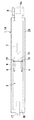
図1〜図3は本実施形態の長尺表面燃焼バーナ1として、メタルニットバーナ1Aの一例を示している。このメタルニットバーナ1Aの細長い燃焼面2は、図3に示すように、耐熱金属繊維7をニット状に編み込んで形成されている。燃焼面2の外周部はバーナハウジング28の下部外周のフランジ部28aに固着されている。なお、燃焼面2の下面近傍には予混合ガス3を放電により点火する点火装置(図示せず)が設けられる。   1 to 3 show an example of a metal knit burner 1A as the long surface combustion burner 1 of this embodiment. The elongated combustion surface 2 of the metal knit burner 1A is formed by knitting heat-resistant metal fibers 7 in a knit shape as shown in FIG. The outer peripheral portion of the combustion surface 2 is fixed to a flange portion 28 a on the lower outer periphery of the burner housing 28. An ignition device (not shown) for igniting the premixed gas 3 by discharge is provided near the lower surface of the combustion surface 2.

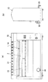
上記燃焼面2の背後には、図1(a)に示すように、長尺の均一板6が燃焼面2と平行に配置されている。均一板6には予混合ガスが通過する多数の開口孔5が散在しており、ガス流出口4からの予混合ガス3が燃焼面2の中心部に過度に流入するのを防止することで温度ムラをなくす働きをする。本例では、図4に示すように、均一板6を樋状の耐熱金属板で構成し、両側の壁部18,18で囲まれた平坦部分にその長手方向Aに間隔をあけて多数の開口孔5からなる小孔群が穿設されている。この小孔群は幅方向Bに例えば2列〜4列程度設けられる。各開口孔5は図4(a)の矢印aで示すように、均一板6の上面から下面側に向って抜き加工された円孔状のパンチング孔で形成されている。ここでは、均一板6は図4(a)のように3ゾーンに分かれており、均一板6の中央部6aのゾーンでは例えば直径2mmの小さめの開口孔5’とし、両端部側のゾーンでは例えば直径3mmの大きめの開口孔5”としてしている。   A long uniform plate 6 is disposed behind the combustion surface 2 in parallel with the combustion surface 2 as shown in FIG. The uniform plate 6 has a large number of opening holes 5 through which the premixed gas passes. By preventing the premixed gas 3 from the gas outlet 4 from flowing into the center of the combustion surface 2 excessively. It works to eliminate temperature unevenness. In this example, as shown in FIG. 4, the uniform plate 6 is formed of a bowl-shaped heat-resistant metal plate, and a large number of flat portions surrounded by the wall portions 18, 18 on both sides are spaced apart in the longitudinal direction A. A small hole group consisting of the opening holes 5 is formed. The small hole group is provided in the width direction B, for example, about 2 to 4 rows. Each opening hole 5 is formed by a circular punching hole that is punched from the upper surface of the uniform plate 6 toward the lower surface side, as indicated by an arrow a in FIG. Here, the uniform plate 6 is divided into three zones as shown in FIG. 4 (a). In the zone of the central portion 6a of the uniform plate 6, for example, a small opening hole 5 'having a diameter of 2 mm is formed. For example, a large opening hole 5 ″ having a diameter of 3 mm is used.

なお、本例では開口孔5(5’,5”)は円形孔で形成されているが、円形孔以外に、例えば角形孔やスリット状の孔であってもよいものであり、また開口孔5の数や位置も図4(a)のように3つのゾーン6a,6b,6bに分けて形成される必要もない。また図4(a)において中央部6aの開口孔5’のうち、最も中心側を最も小さい孔とし、中心から離れた両側の開口孔を一回り大きい孔(例えば、2mm以上、3mm以下の孔)としてもよいものであり、要するに均一板6の中心から両端側になるほど開口面積よりも大きくした構造であればよく、孔の形状、大きさ、配置等は適宜設計変更自在である。   In this example, the opening hole 5 (5 ′, 5 ″) is a circular hole, but other than the circular hole, for example, a square hole or a slit-like hole may be used. 4 does not need to be divided into three zones 6a, 6b, and 6b as shown in Fig. 4 (a), and in Fig. 4 (a), among the opening holes 5 'in the central portion 6a, The smallest hole may be the smallest hole, and the opening holes on both sides away from the center may be slightly larger (for example, holes of 2 mm or more and 3 mm or less). In short, from the center of the uniform plate 6 to both ends. As long as it has a structure larger than the opening area, the shape, size, arrangement, etc. of the holes can be appropriately changed.

上記均一板6の背後には、図1(a)のように予混合ガス3を一時的に溜める筒状空間部8が設置されている。筒状空間部8の中央側にガス流出口4が設けられ、筒状空間部8の一端部8a側にはガス取入れ口9が設けられている。ガス管から供給される燃焼ガスは混合器(図示せず)で一次空気と予混合され、この予混合ガス3が直流ファン(図示せず)によって上記ガス取入れ口9から筒状空間部8内に流入するようになっている。   Behind the uniform plate 6 is a cylindrical space 8 for temporarily storing the premixed gas 3 as shown in FIG. A gas outlet 4 is provided on the center side of the cylindrical space portion 8, and a gas inlet 9 is provided on the one end 8 a side of the cylindrical space portion 8. Combustion gas supplied from the gas pipe is premixed with primary air in a mixer (not shown), and this premixed gas 3 is passed through the gas intake port 9 into the cylindrical space 8 by a direct current fan (not shown). To flow into.

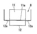
さらに、上記筒状空間部8内には、図5に示すように、ガス取入れ口9とガス流出口4との間を遮るように壁状の第1のバッフル板11が立設されている。バッフル板11の両サイドには図2(a)の矢印dのように予混合ガス3が通り抜け可能な通気部19が設けられている。バッフル板11の下部11aは図5に示すように、L字状に折曲されていて、ガス流出口4よりもガス取入れ口9側にずれた位置で例えば3点スポット溶接にて筒状空間部8の底面に固着してある。このバッフル板11は予混合ガス3を筒状空間部8内に均一に分散する働きをする。ちなみに、予混合ガス3を筒状空間部8内に均一に分散させるためには、筒状空間部8の容積を大きくとることで解決できるが、この場合は、バーナサイズが大きくなりすぎるという不具合が生じるが、本例では第1のバッフル板11を用いることでかかる不具合をなくすことができる。   Further, as shown in FIG. 5, a wall-shaped first baffle plate 11 is erected in the cylindrical space 8 so as to block between the gas inlet 9 and the gas outlet 4. . Vent portions 19 through which the premixed gas 3 can pass are provided on both sides of the baffle plate 11 as indicated by an arrow d in FIG. As shown in FIG. 5, the lower part 11a of the baffle plate 11 is bent in an L shape, and is, for example, three-point spot welded at a position shifted from the gas outlet 4 to the gas inlet 9 side. It is fixed to the bottom surface of the part 8. The baffle plate 11 functions to uniformly disperse the premixed gas 3 in the cylindrical space 8. Incidentally, in order to uniformly disperse the premixed gas 3 in the cylindrical space portion 8, it can be solved by increasing the volume of the cylindrical space portion 8, but in this case, the burner size becomes too large. However, this problem can be eliminated by using the first baffle plate 11 in this example.

さらに、ガス流出口4の下方には、均一板6の中央部6aと対向する第2のバッフル板12が配置されている。本例では、第2のバッフル板12は側方から見て樋状に形成されており、ガス流出口4の下面の両サイドにバッフル板12の両端部12aが例えば3点スポット溶接にて固着されている。樋状のバッフル板12は均一板6の両端部6b,6b側にそれぞれ開口しており、ガス流出口4から流出した予混合ガス3が均一板6の中央部6aへ過度に流入するのを防止できると同時に、図5(b)の矢印bで示すように、均一板6の両端部6b,6b側にそれぞれ拡散できる構造となっている。なお、メタルニットバーナ1Aの長さは例えば700mmとされるが、もちろんこの数値に限られるものではない。なお図2中の17はメタルニットバーナ1Aの先端を支える固定板である。   Further, a second baffle plate 12 facing the central portion 6 a of the uniform plate 6 is disposed below the gas outlet 4. In this example, the second baffle plate 12 is formed in a bowl shape when viewed from the side, and both end portions 12a of the baffle plate 12 are fixed to both sides of the lower surface of the gas outlet 4 by, for example, three-point spot welding. Has been. The bowl-shaped baffle plate 12 is opened to both ends 6b and 6b of the uniform plate 6 so that the premixed gas 3 flowing out from the gas outlet 4 flows into the central portion 6a of the uniform plate 6 excessively. At the same time, as shown by the arrow b in FIG. 5 (b), the uniform plate 6 can be diffused to both ends 6b and 6b. The length of the metal knit burner 1A is 700 mm, for example, but it is not limited to this value. Note that reference numeral 17 in FIG. 2 denotes a fixing plate that supports the tip of the metal knit burner 1A.

上記構成において、筒状空間部8の一端部8a側から流入した予混合ガス3は、第1のバッフル板11に当たり、その背後にあるガス流出口4にそのまま流出することがなく、予混合ガス3の一部が第1のバッフル板11にはね返され、残りが通気部19を通過することで、筒状空間部8の両端部8a,8b側にそれぞれ予混合ガス3が行き渡るようになり、筒状空間部8内に均一に分散する。その後、ガス圧が高まるとガス流出口4から予混合ガス3が流出し、第2のバッフル板12に当たる。これにより予混合ガス3が均一板6の中央部6aに過度に流出するのを防止できると共に均一板6の両端部6b,6b側に向ってそれぞれ拡散するので、予混合ガス3の流速分布が均一板6全体で均一となる。さらに均一板6の中央部6a側の各開口孔5’は小さく、ガス流出口4から離れた両端部6b側の各開口孔5”はそれぞれ大きく形成されているため、均一板6の両端部6b,6b側まで予混合ガス3が十分に行き渡るようになり、均一板6の中央部6a側と両端部6b側とで予混合ガス3の単位時間あたりの送り込み量をほぼ同じ程度にすることができる。この結果、長尺のバーナ全体に予混合ガス3が行き渡り、燃焼面2全体が赤熱して均一に燃焼するので、温度ムラを改善することができ、長尺の燃焼面2により均一な加熱調理を実現できる効果が得られる。   In the above configuration, the premixed gas 3 that has flowed in from the one end 8a side of the cylindrical space 8 hits the first baffle plate 11 and does not flow out as it is to the gas outlet 4 behind it, but the premixed gas 3 3 is rebounded to the first baffle plate 11, and the remainder passes through the ventilation part 19, so that the premixed gas 3 spreads to both ends 8 a and 8 b of the cylindrical space part 8. It is uniformly dispersed in the cylindrical space 8. Thereafter, when the gas pressure increases, the premixed gas 3 flows out from the gas outlet 4 and hits the second baffle plate 12. As a result, the premixed gas 3 can be prevented from excessively flowing out to the central portion 6a of the uniform plate 6 and diffused toward both ends 6b, 6b of the uniform plate 6, so that the flow velocity distribution of the premixed gas 3 is The entire uniform plate 6 is uniform. Furthermore, since each opening hole 5 ′ on the central portion 6a side of the uniform plate 6 is small and each opening hole 5 ″ on both end portions 6b side away from the gas outlet 4 is formed large, both end portions of the uniform plate 6 are formed. The premixed gas 3 is sufficiently distributed to the 6b and 6b sides, and the feeding amount per unit time of the premixed gas 3 on the central portion 6a side and the both end portions 6b side of the uniform plate 6 is made approximately the same. As a result, the premixed gas 3 spreads over the entire long burner, and the entire combustion surface 2 is red-heated and burns uniformly, so that temperature unevenness can be improved and the long combustion surface 2 is more uniform. The effect which can implement | achieve simple heating cooking is acquired.

しかも、各バッフル板11,12は設置が簡単であり、構造をシンプル化できるようになる。しかも均一板6をパンチングメタル等の多孔板を用いて容易に構成できると共に、均一板6の製造が容易となるため、コスト面でも有利となる。   Moreover, the baffle plates 11 and 12 are easy to install, and the structure can be simplified. In addition, the uniform plate 6 can be easily constructed using a perforated plate such as a punching metal, and the production of the uniform plate 6 is facilitated, which is advantageous in terms of cost.

また本例のメタルニットバーナ1Aは従来のセラミックバーナと比較して以下の効果がある。すなわち、(1)燃焼面2のサイズを自由に変更できる効果、(2)バーナの形状を被加熱物の形状に合わせて設計でき、バーナの加工が容易になる効果、(3)燃焼面2の形状を例えば波状、半筒状等に自由にさまざまな形状に加工でき、これにより単位面積あたりの熱負荷(バーナ面負荷)が大きくとれるので、燃焼範囲が広くガス圧や風量変動にも影響しない安定燃焼を確保できる効果、(4)従来のセラミックプレートでは決まったサイズのプレートしかないため、バーナ1本当たりの面負荷が小さく、燃焼量が限定されてしまい、火力が必要なときはバーナ数を増加させる必要もあるが、メタルニットバーナ1Aにおいては大きな熱負荷を確保できるので、セラミックバーナのような問題を解消できると同時に、薄くてコンパクトにでき、設置スペースをとらない効果、(5)さらに、外的衝撃に強くなる効果、(6)昇温冷却の応答が速く、予熱時間が半減し、ターンダウン比を大きくできるため、取り扱いが簡単であると同時に高効率運転が実現する効果、(7)バーナの圧力損失が少ない効果、(8)バーナ表面からの輻射と高温燃焼ガスの対流とで効率の高い加熱ができる効果、(9)窒素酸化物や一酸化炭素の発生がなく、環境面でも優れている効果がある。このような優れた様々な効果を有するメタルニットバーナ1において、本発明にあっては、均一板6を配置した構造、さらにバッフル板11,12を配置した構造を採用することで温度ムラを改善できるという、従来のメタルニットバーナでは得られない独自の効果を奏するものである。   Further, the metal knit burner 1A of the present example has the following effects compared to the conventional ceramic burner. That is, (1) the effect that the size of the combustion surface 2 can be freely changed, (2) the effect that the shape of the burner can be designed according to the shape of the object to be heated, and the burner can be easily processed, (3) the combustion surface 2 Can be processed into various shapes such as corrugated, semi-cylindrical, etc., so that the heat load (burner surface load) per unit area can be increased, so the combustion range is wide and it affects gas pressure and air flow fluctuations. (4) Since the conventional ceramic plate has only a fixed size plate, the surface load per burner is small, the amount of combustion is limited, and the burner is required when thermal power is required. Although it is necessary to increase the number, the metal knit burner 1A can secure a large heat load, so it can solve the problems of ceramic burners, and is thin and compact. Easy to handle because it does not take up installation space, (5) In addition, it is resistant to external impacts, (6) Quick response to heating and cooling, preheating time is halved and turn-down ratio can be increased (7) The effect of realizing high-efficiency operation at the same time, (7) The effect of reducing the pressure loss of the burner, (8) The effect of heating with high efficiency by the radiation from the burner surface and the convection of the high-temperature combustion gas, (9) There is no generation of nitrogen oxides or carbon monoxide, and there is an excellent effect in terms of environment. In the metal knit burner 1 having such various excellent effects, in the present invention, the temperature unevenness is improved by adopting the structure in which the uniform plate 6 is arranged and the structure in which the baffle plates 11 and 12 are arranged. This is a unique effect that cannot be obtained with conventional metal knit burners.

図7〜図9は、本発明に係るメタルニットバーナ1A(図1〜図3)を用いた上火式焼き物器10の一例を示している。この上火式焼き物器10は、例えば業務用の焼き鳥器として使用されるものである。もちろん焼き鳥器以外にも使用可能である。ここでは被焼成物を載せる焼物支持部15の上方に、上火用バーナ14を構成するメタルニットバーナ1Aを設置し、被焼成物から出る油等を受ける受け皿或いは水槽16を焼物支持部15の下方に配置してある。なお図7中の29はガス管差しこみ部、30は操作ハンドル又はレバー、図8中の31は排気孔付き天板である。しかして、加熱調理中は冷却用送風機32による空気の流れは、図9のように水槽設置台22の下部のスリット部21と、水槽16の横のガラリ部23との2箇所から吹き出るようになり、水槽16を冷却する空気の流れとなり、さらにこの空気の流れは、焼き鳥の串60を冷却し、さらに串60を返す調理人の手を冷却するような熱遮断用のエアーカーテンHとなる。さらにこのエアーカーテンHは加熱時の排ガスGを冷却しながら外部に排出させる働きをし、これにより調理環境も良好となる。また本発明に係るメタルニットバーナ1Aは、二次空気を必要としない全一次空気燃焼であるため、排気の影響を受けずに使用可能となる。また本発明の温度ムラのないメタルニットバーナ1Aを使用することで、調理ムラをなくして、焼き上がり品質を高めることができるものである。   FIGS. 7-9 has shown an example of the top-fire type pottery device 10 using the metal knit burner 1A (FIGS. 1-3) which concerns on this invention. The upper-fire type pottery device 10 is used, for example, as a commercial yakitori device. Of course, it can be used for other than yakitori. Here, a metal knit burner 1 </ b> A constituting the upper-burn burner 14 is installed above the pottery support 15 on which the object to be fired is placed. It is arranged below. In FIG. 7, 29 is a gas pipe insertion portion, 30 is an operation handle or lever, and 31 in FIG. 8 is a top plate with an exhaust hole. Thus, during cooking, the air flow from the cooling blower 32 is blown out from two locations, the slit portion 21 at the bottom of the aquarium installation table 22 and the side wall portion 23 of the aquarium 16 as shown in FIG. It becomes an air flow that cools the water tank 16, and this air flow further becomes an air curtain H for heat insulation that cools the grilled chicken skewer 60 and further cools the cook's hand that returns the skewer 60. . Further, the air curtain H serves to discharge the exhaust gas G during heating to the outside while cooling, thereby improving the cooking environment. Further, the metal knit burner 1A according to the present invention is all primary air combustion that does not require secondary air, and therefore can be used without being affected by exhaust. Further, by using the metal knit burner 1A having no temperature unevenness according to the present invention, cooking unevenness can be eliminated and the baking quality can be improved.

なお、本発明の均一板6を配置した構造、さらにバッフル板11,12を設けた構造は、メタルニットバーナ1A以外にセラミックバーナ等の長尺表面燃焼バーナ1にも同様に適用可能である。   In addition, the structure which arrange | positioned the uniform board 6 of this invention, and also the structure which provided the baffle plates 11 and 12 are applicable similarly to elongate surface combustion burners 1, such as a ceramic burner, besides metal knit burner 1A.

また本発明に係る長尺表面燃焼バーナ1は、図7〜図9の上火式焼き物器10以外に、上下にバーナを設けた両面焼き物器にも適用可能であり、さらには調理器以外の暖房、ボイラ、乾燥機等の各種の熱処理関連分野にも広く適用可能である。   Moreover, the long surface combustion burner 1 which concerns on this invention is applicable also to the double-sided ceramic device which provided the burner in the upper and lower sides other than the upper-fired-type ceramic device 10 of FIGS. The present invention can be widely applied to various heat treatment related fields such as heating, boilers and dryers.

本発明の一実施形態を示し、(a)はメタルニットバーナの一部切欠正面図、(b)は左側面図、(c)は右側面図である。1 shows an embodiment of the present invention, in which (a) is a partially cutaway front view of a metal knit burner, (b) is a left side view, and (c) is a right side view. 同上のメタルニットバーナの平面図である。It is a top view of a metal knit burner same as the above. 同上のメタルニットバーナの底面図である。It is a bottom view of a metal knit burner same as the above. (a)は同上の均一板の平面図、(b)は正面図、(c)は側面図である。(A) is a top view of the uniform board same as the above, (b) is a front view, (c) is a side view. (a)は同上の筒状空間部の平面図、(b)は正面断面図である。(A) is a top view of a cylindrical space part same as the above, (b) is a front sectional view. 同上の筒状空間部の側面図である。It is a side view of the cylindrical space part same as the above. (a)は同上の長尺表面燃焼バーナを用いた上火式焼き物器の正面図、(b)は側面図である。(A) is a front view of the upper-fire type pottery using the same long surface combustion burner, and (b) is a side view. 同上の上火式焼き物器の平面図である。It is a top view of an upper-fire type pottery same as the above. 同上の上火式焼き物器の内部構造の説明図である。It is explanatory drawing of the internal structure of an upper-fire type pottery same as the above.

符号の説明Explanation of symbols

1 長尺表面燃焼バーナ
1A メタルニットバーナ
2 燃焼面
3 予混合ガス
4 ガス流出口
5 開口孔
6 均一板
6a 中央部
6b 端部
7 耐熱金属繊維
8 筒状空間部
8a,8b 端部
9 ガス取入れ口
10 上火式焼き物器
11 第1のバッフル板
12 第2のバッフル板
14 上火用バーナ
15 焼物支持部
16 水槽
DESCRIPTION OF SYMBOLS 1 Long surface combustion burner 1A Metal knit burner 2 Combustion surface 3 Premixed gas 4 Gas outlet 5 Open hole 6 Uniform plate 6a Center part 6b End part 7 Heat-resistant metal fiber 8 Cylindrical space part 8a, 8b End part 9 Gas intake Mouth 10 Upper-fired pottery 11 First baffle plate 12 Second baffle plate 14 Upper-burner 15 Pottery support 16 Water tank

Claims (4)

燃焼面が細長く形成され、燃焼面の中心部の背後に予混合ガスを燃焼面に向って供給するガス流出口が配置された長尺表面燃焼バーナであって、上記細長い燃焼面とガス流出口との間に、複数の開口孔を有する長尺の均一板を配置し、上記複数の開口孔の開口面積を均一板の中央部側よりも両端部側の方が大きくなるように形成すると共に、上記均一板の背後に予混合ガスを一時的に溜める筒状空間部を設置し、筒状空間部の端部側にガス取入れ口を設け、上記ガス流出口を筒状空間部の中央側に設け、筒状空間部内におけるガス取入れ口とガス流出口との間に、ガス取入れ口から取り込まれる予混合ガスを筒状空間部の両端部側にそれぞれ拡散させるための第1のバッフル板を配置したことを特徴とする長尺表面燃焼バーナ。 A long surface combustion burner having a long and narrow combustion surface and a gas outlet for supplying premixed gas toward the combustion surface behind the center of the combustion surface, the elongated combustion surface and the gas outlet between placing a uniform plate elongated having a plurality of openings, and forming as toward the both ends than the central portion of uniform plate opening area of the plurality of openings is increased A cylindrical space part for temporarily storing the premixed gas behind the uniform plate, a gas intake port is provided on the end side of the cylindrical space part, and the gas outlet is located on the center side of the cylindrical space part. And a first baffle plate for diffusing the premixed gas taken from the gas intake port to both ends of the cylindrical space portion between the gas intake port and the gas outlet port in the cylindrical space portion. A long surface combustion burner characterized by being arranged . 上記燃焼面が耐熱金属繊維をニット状に編み込んで形成されたメタルニットバーナであることを特徴とする請求項1記載の長尺表面燃焼バーナ。   The long surface combustion burner according to claim 1, wherein the combustion surface is a metal knit burner formed by knitting heat-resistant metal fibers in a knit shape. 上記ガス流出口と均一板との間に、ガス流出口から流出する予混合ガスを均一板の両端部側にそれぞれ拡散させるための第2のバッフル板を配置したことを特徴とする請求項1又は2記載の長尺表面燃焼バーナ。 2. A second baffle plate for diffusing the premixed gas flowing out from the gas outlet to both ends of the uniform plate is disposed between the gas outlet and the uniform plate. Or the long surface combustion burner of 2. 上記均一板に形成される各開口孔を円形孔で形成したことを特徴とする請求項1乃至3のいずれかに記載の長尺表面燃焼バーナ。 Long surface combustion burners according to any one of claims 1 to 3, characterized in that the formation of the respective openings formed in said uniform plate with a circular hole.
JP2003381438A 2003-11-11 2003-11-11 Long surface combustion burner Expired - Fee Related JP4095539B2 (en)

Priority Applications (1)

Application Number Priority Date Filing Date Title
JP2003381438A JP4095539B2 (en) 2003-11-11 2003-11-11 Long surface combustion burner

Applications Claiming Priority (1)

Application Number Priority Date Filing Date Title
JP2003381438A JP4095539B2 (en) 2003-11-11 2003-11-11 Long surface combustion burner

Publications (2)

Publication Number Publication Date
JP2005147423A JP2005147423A (en) 2005-06-09
JP4095539B2 true JP4095539B2 (en) 2008-06-04

Family

ID=34690811

Family Applications (1)

Application Number Title Priority Date Filing Date
JP2003381438A Expired - Fee Related JP4095539B2 (en) 2003-11-11 2003-11-11 Long surface combustion burner

Country Status (1)

Country Link
JP (1) JP4095539B2 (en)

Families Citing this family (1)

* Cited by examiner, † Cited by third party
Publication number Priority date Publication date Assignee Title
JP6404967B2 (en) * 2017-03-02 2018-10-17 株式会社中西製作所 Continuous rice cooker

Also Published As

Publication number Publication date
JP2005147423A (en) 2005-06-09

Similar Documents

Publication Publication Date Title
EP2310742B1 (en) Cooktop swirl burner
JP5566305B2 (en) Open loop gas burner
US20060292510A1 (en) Radiant gas burner
AU2015203977B2 (en) Multi-cone fuel burner apparatus for multi-tube heat exchanger
AU7143300A (en) Low emission combustion system
US20020076669A1 (en) NOx reduction device
JP3814603B2 (en) Premixed gas combustion burner with separated flame holes
WO2013107661A2 (en) Cylindrical gas premix burner
JP4095539B2 (en) Long surface combustion burner
JP4677385B2 (en) grill
CN112066369B (en) Combustor, hanging stove and water heater
KR102365634B1 (en) Metal fiber burner for boiler
US2771132A (en) Radiant gas burner apparatus
JP3534602B2 (en) Concentration combustion device
JP3947514B2 (en) Metal knit burner
EP3126737B1 (en) Pre-mixed gas burner cooled by an air-gas mixture
CN220567244U (en) Fire row, burner and water heating device
JP4085272B2 (en) Gas burner
JPH08312922A (en) Grill burner
JP2004176990A (en) Burner mounting structure for water heater
JP2005274024A (en) Gas range
JP2663443B2 (en) Fluid fuel combustion device
JP4375789B2 (en) Gas stove
KR200387964Y1 (en) Tube heater
JPH0227305Y2 (en)

Legal Events

Date Code Title Description
A621 Written request for application examination

Free format text: JAPANESE INTERMEDIATE CODE: A621

Effective date: 20061109

A977 Report on retrieval

Free format text: JAPANESE INTERMEDIATE CODE: A971007

Effective date: 20071023

A131 Notification of reasons for refusal

Free format text: JAPANESE INTERMEDIATE CODE: A131

Effective date: 20071113

A521 Written amendment

Free format text: JAPANESE INTERMEDIATE CODE: A523

Effective date: 20080107

TRDD Decision of grant or rejection written
A01 Written decision to grant a patent or to grant a registration (utility model)

Free format text: JAPANESE INTERMEDIATE CODE: A01

Effective date: 20080212

A61 First payment of annual fees (during grant procedure)

Free format text: JAPANESE INTERMEDIATE CODE: A61

Effective date: 20080307

FPAY Renewal fee payment (event date is renewal date of database)

Free format text: PAYMENT UNTIL: 20110314

Year of fee payment: 3

R150 Certificate of patent or registration of utility model

Ref document number: 4095539

Country of ref document: JP

Free format text: JAPANESE INTERMEDIATE CODE: R150

Free format text: JAPANESE INTERMEDIATE CODE: R150

R250 Receipt of annual fees

Free format text: JAPANESE INTERMEDIATE CODE: R250

R250 Receipt of annual fees

Free format text: JAPANESE INTERMEDIATE CODE: R250

R250 Receipt of annual fees

Free format text: JAPANESE INTERMEDIATE CODE: R250

R250 Receipt of annual fees

Free format text: JAPANESE INTERMEDIATE CODE: R250

R250 Receipt of annual fees

Free format text: JAPANESE INTERMEDIATE CODE: R250

R250 Receipt of annual fees

Free format text: JAPANESE INTERMEDIATE CODE: R250

R250 Receipt of annual fees

Free format text: JAPANESE INTERMEDIATE CODE: R250

LAPS Cancellation because of no payment of annual fees