JP4090699B2 - Biological light measurement device - Google Patents
Biological light measurement device Download PDFInfo
- Publication number
- JP4090699B2 JP4090699B2 JP2001102806A JP2001102806A JP4090699B2 JP 4090699 B2 JP4090699 B2 JP 4090699B2 JP 2001102806 A JP2001102806 A JP 2001102806A JP 2001102806 A JP2001102806 A JP 2001102806A JP 4090699 B2 JP4090699 B2 JP 4090699B2
- Authority
- JP
- Japan
- Prior art keywords
- optical waveguide
- light
- subject
- optical
- living body
- Prior art date
- Legal status (The legal status is an assumption and is not a legal conclusion. Google has not performed a legal analysis and makes no representation as to the accuracy of the status listed.)
- Expired - Fee Related
Links
Images


Classifications
-
- A—HUMAN NECESSITIES
- A61—MEDICAL OR VETERINARY SCIENCE; HYGIENE
- A61B—DIAGNOSIS; SURGERY; IDENTIFICATION
- A61B5/00—Measuring for diagnostic purposes; Identification of persons
- A61B5/68—Arrangements of detecting, measuring or recording means, e.g. sensors, in relation to patient
- A61B5/6801—Arrangements of detecting, measuring or recording means, e.g. sensors, in relation to patient specially adapted to be attached to or worn on the body surface
- A61B5/6813—Specially adapted to be attached to a specific body part
- A61B5/6814—Head
-
- A—HUMAN NECESSITIES
- A61—MEDICAL OR VETERINARY SCIENCE; HYGIENE
- A61B—DIAGNOSIS; SURGERY; IDENTIFICATION
- A61B5/00—Measuring for diagnostic purposes; Identification of persons
- A61B5/0059—Measuring for diagnostic purposes; Identification of persons using light, e.g. diagnosis by transillumination, diascopy, fluorescence
-
- A—HUMAN NECESSITIES
- A61—MEDICAL OR VETERINARY SCIENCE; HYGIENE
- A61B—DIAGNOSIS; SURGERY; IDENTIFICATION
- A61B5/00—Measuring for diagnostic purposes; Identification of persons
- A61B5/145—Measuring characteristics of blood in vivo, e.g. gas concentration, pH value; Measuring characteristics of body fluids or tissues, e.g. interstitial fluid, cerebral tissue
- A61B5/1455—Measuring characteristics of blood in vivo, e.g. gas concentration, pH value; Measuring characteristics of body fluids or tissues, e.g. interstitial fluid, cerebral tissue using optical sensors, e.g. spectral photometrical oximeters
- A61B5/14551—Measuring characteristics of blood in vivo, e.g. gas concentration, pH value; Measuring characteristics of body fluids or tissues, e.g. interstitial fluid, cerebral tissue using optical sensors, e.g. spectral photometrical oximeters for measuring blood gases
- A61B5/14552—Details of sensors specially adapted therefor
-
- A—HUMAN NECESSITIES
- A61—MEDICAL OR VETERINARY SCIENCE; HYGIENE
- A61B—DIAGNOSIS; SURGERY; IDENTIFICATION
- A61B5/00—Measuring for diagnostic purposes; Identification of persons
- A61B5/145—Measuring characteristics of blood in vivo, e.g. gas concentration, pH value; Measuring characteristics of body fluids or tissues, e.g. interstitial fluid, cerebral tissue
- A61B5/1455—Measuring characteristics of blood in vivo, e.g. gas concentration, pH value; Measuring characteristics of body fluids or tissues, e.g. interstitial fluid, cerebral tissue using optical sensors, e.g. spectral photometrical oximeters
- A61B5/14551—Measuring characteristics of blood in vivo, e.g. gas concentration, pH value; Measuring characteristics of body fluids or tissues, e.g. interstitial fluid, cerebral tissue using optical sensors, e.g. spectral photometrical oximeters for measuring blood gases
- A61B5/14553—Measuring characteristics of blood in vivo, e.g. gas concentration, pH value; Measuring characteristics of body fluids or tissues, e.g. interstitial fluid, cerebral tissue using optical sensors, e.g. spectral photometrical oximeters for measuring blood gases specially adapted for cerebral tissue
-
- A—HUMAN NECESSITIES
- A61—MEDICAL OR VETERINARY SCIENCE; HYGIENE
- A61B—DIAGNOSIS; SURGERY; IDENTIFICATION
- A61B2562/00—Details of sensors; Constructional details of sensor housings or probes; Accessories for sensors
- A61B2562/02—Details of sensors specially adapted for in-vivo measurements
- A61B2562/0233—Special features of optical sensors or probes classified in A61B5/00
-
- A—HUMAN NECESSITIES
- A61—MEDICAL OR VETERINARY SCIENCE; HYGIENE
- A61B—DIAGNOSIS; SURGERY; IDENTIFICATION
- A61B2562/00—Details of sensors; Constructional details of sensor housings or probes; Accessories for sensors
- A61B2562/04—Arrangements of multiple sensors of the same type
- A61B2562/046—Arrangements of multiple sensors of the same type in a matrix array
Description
【0001】
【発明の属する技術分野】
本発明は、光を用い、生体内部の代謝物質を計測する生体光計測装置に関する。
【0002】
【従来の技術】
光を用いた生体計測では、可視から近赤外の光を用いた生体機能を計測する装置が、例えば特開昭57−115232号公報あるいは特開昭63−275323号公報で開示されている。さらに、本計測原理を応用し、脳機能の画像計測技術に関する発明(光トポグラフィ)が特開平9−98972公報に提案されている。
【0003】
これらは、光ファイバー等で代表されるような光導波手段を用い、生体に光を照射し数mmから数cm離れた位置で生体内部で散乱された光(以降、生体散乱光と略す。)を集光計測する。計測された生体散乱光の強度より、酸化ヘモグロビン及び還元ヘモグロビン等で代表されるような生体内部の光吸収物質濃度あるいは濃度に相当する値を求める。光吸収物質濃度あるいは濃度に相当する値を求める際には、照射した光の波長に対応した、目的とする光吸収物質の光吸収特性を用いる。一般的に、生体深部を計測する場合には、生体透過性の高い650nmから1300nmの範囲内にある波長の光を用いる。
【0004】
【発明が解決しようとする課題】
生体光計測においては、被検査体(生体)に光を照射する手段(以降、光照射手段と称す。)と生体内部を伝播した通過光を集光する手段(以降、集光手段と称す。)を有している。これら光照射手段と集光手段としては、光ファイバーあるいは光ファイバー束で代表されるような光導波路を具備することが多い。また、1組の光照射用および集光用の光導波路が、1計測位置を表す最小単位(以降、光照射集光ペアと略す。)である。この最小単位を複数設定し、生体の画像計測を行う装置が、特開平9−98972号公報に提案されている。
【0005】
ここで、光照射集光ペアの照射位置と集光位置間の距離(以降、光照射集光ペア間距離と称す。)は、計測対象となる領域の広さあるいは深さによって変わる。そのため、特開平9−98972号公報では、各光照射集光ペア間距離が等間隔になるように、光照射用の光導波路と集光用の光導波路を、正方格子の頂点上に交互に配置する配置形態を提案している。この配置形態を用いれば、1つの光導波路が複数の光照射集光ペアに共有される形となるため、少ない光導波路で画像計測が可能となる。従って、短時間で光導波路を生体に装着することができる。
【0006】
しかし、この配置形態は、生体の平面で近似できる程度の生体の狭い領域(例えば、頭の場合では15cm四方程度)への適用は容易であるが、曲率の大きい領域への適用は困難である。特に、新生児・乳幼児の頭部形状などは、大きな曲率を有し、個人差も大きい。また、新生児・乳幼児などを計測する場合には、被検者が静かに待機してもらうことが不可能であるため、動きによるプローブのずれも抑制しなければならない等、大人では想定できなかった問題が生じる。
【0007】
特に、新生児・乳幼児の脳機能を計測する手段は、これまでのところ脳波計に限定されている。しかし、脳波計は空間分解能が余り高くなく、脳中心部の脳幹部・脳表面の大脳皮質の情報を分離することが困難である。一方、光計測に基づく脳機能計測方法は、人間において特に発達した高次脳機能に強く連関をもつ大脳皮質の無侵襲計測が可能であるため、高次機能の発達過程を知る上で非常に有効な手法であることが期待されていた。
【0008】
しかし、原理的に有効であることは知られているが、光を照射および集光する導波路を固定する固定具(プローブ)がこれまでのところ開発されていなかった。
【0009】
そこで、実用的な新生児・乳幼児のための生体光計測用光導波路プローブを構成するためには、次のような点が要求される。以下、列挙する。
(1)柔軟性:
使用される生体光計測用プローブは、曲率を有する生体表面に柔軟に適合可能でなければならない。
(2)入射検出用導波路間距離保持能力:
使用される生体光計測用プローブは、個人差を有する形状に対して、入射検出用導波路間距離(正確には、光照射用光導波路の先端と集光用光導波路の先端部間の道のりであるが、以降、便宜的に入射検出間距離と称す。)が、所定の許容範囲以上には変わってはならない。
(3)体動追従性:
使用される生体光計測用プローブは、ある程度の動きを伴っていても、ずれてはならない。
(4)密着度視認性:
使用される生体光計測用プローブは、光導波路と生体表面との密着性が確認できるように、視認性が高く、容易に密着状態を制御できなければならない。
(5)快適性:
新生児や乳幼児など、環境変化に適応能力の低い被検者の場合には、温度変化の観点から完全に頭部などを覆うこがあってはならない。
(6)圧力分散性:
新生児や乳幼児など、デリケートな頭部を持つ被検者の場合には、1点に高い圧力をかけてはならない。
(7)形状保持性:
被検者に与える不可を減らすため、短時間でプローブを装着する必要があるため、容易に形状を変化でき、かつ、基本的な形状を保持する必要がある。
(8)装着性:
上記課題7と同様の理由で、容易にプローブを固定する手段が必要である。
(9)固定手段の形状・サイズ適応性:
固定する手段が、被検者の頭部形状に適応できる必要がある。
(10)固定手段の加圧性:
固定する手段が、適度な圧力を与えることができる必要がある。
【0010】
本発明は、上記の点に鑑みてなされたものであり、生体光計測において、曲率が大きく、動きのある生体部位に対して装着可能なプローブを備えた生体光計測装置を提供することを目的とする。
【0011】
【課題を解決するための手段】
上記目的を達成するために、本発明では、入射用光導波路および集光用光導波路先端を、柔軟な素材で連結した。ただし、この柔軟な素材は、入射検出間距離が変わらないように、あまり伸縮性のない素材が好ましい。例えば、シリコンラバーなどが適切である。
【0012】
また、本発明では、上記目的を達成するために、生体に接触する面に摩擦係数の高い素材を配置し、さらに各導波路に適度な圧力を加えるために、伸縮性のある素材で各光導波路の先端から1〜2cmのところで連結した。
【0013】
さらに、本発明では、上記目的を達成するために、光導波路先端を連結する素材及び光導波路先端から1〜2cmのところを連結する素材において、連結に不要な部分は除去して視認性を確保した。また、光導波路の生体への密着性の制御は、伸縮性のある素材で各光導波路の先端から1〜2cmのところで連結することによって容易に解決できた。
【0014】
このように、本発明は、被検査体に光導波路を介して被検査体に光を照射する光照射手段と、前記光照射手段から照射され被検査体内部を伝播した光を光導波路を介して集光する集光手段とを備えたプローブを用いて、被検査体内部の代謝物を計測するようにした生体光計測装置において、前記プローブは、前記光照射手段用および前記集光手段用として、それぞれ複数の光導波路を有し、前記被検査体に接触する部分が少なくとも1つの面構造の部材で構成されていることを特徴とする生体光計測装置を提供する。
【0015】
また、本発明は、前記構成において、前記光照射手段および前記集光手段の各光導波路の先端部が、前記被検査体と接触する面で、各光導波路間の距離が所定の許容範囲内にあるよう支持されていることを特徴とする生体光計測装置を提供する。
【0016】
また、本発明は、前記構成において、前記被検査体に接触する部分が、分割した複数の面構造の部材で構成されていることを特徴とする生体光計測装置を提供する。
【0017】
さらに、本発明は、被検査体に光導波路を介して光を照射する光照射手段と、前記光照射手段から照射され被検査体内部を伝播した光を光導波路を介して集光する集光手段とを備えたプローブを用いて、被検査体内部の代謝物を計測するようにした生体光計測装置において、前記プローブは、被検査体に接触する部分が、分割した複数の面構造の部材で構成され、前記面構造の各部材上には複数の光照射用の光導波路および複数の集光検出用の光導波路を具備し、かつ、前記面構造の各部材間が柔軟性部材を介して連結されていることを特徴とする生体光計測装置を提供する。
【0018】
【発明の実施の形態】
以下、本発明の一実施例について説明する。
【0019】
図1に、本実施例に基づく生体光計測用プローブの光導波路固定部を示す。図2には、前記光導波路の配置形態を示す。図3には、前記光導波路固定部を頭部へ装着する装着手段及びその装着方法を示す。
【0020】
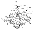
まず、図1に関する説明を行う。基本的にはくり返しパターンで構成されるため、基本構成のみ説明を行う。光源から被検査体に光を照射する光照射用の光導波路は、光導波路保持部1-1-1-aと光導波路部1-1-2-aとで構成される。この光導波路は、光導波路ガイド1−2に挿入される。図中、隣接の集光用の光導波路の光導波路ガイド1−2には、光導波路保持部1-1-1-bと光導波路部1-1-2-bとで構成される光導波路が既に挿入されている状態を示している。本図には、挿入前の光導波路と挿入後の光導波路をそれぞれ1本ずつ示したが、図1中の全ての光導波路ガイドに光導波路は挿入される。また、本実施例では、光導波路固定部の光導波路が9個の場合について示しているが、本例に限定されないことはいうまでもない。
【0021】
光導波路ガイド1−2には、光導波路は接着あるいはネジあるいは一体加工あるいは機械的に固定される。光導波路固定ガイド1−2とクッション部材1−4を接合する接合部材1−3は柔軟なプラスチックなどでできており、光導波路ガイド1−2に刻まれた溝に嵌められている。クッション部材1−4は、例えば,スポンジ、シリコンなど、柔軟性、弾力性のある材料が使用される。
【0022】
また、接合部材1−3の底面(クッション部材1−4に接する面)は、クッション部材部材1−4と接着剤などによって接合されている。クッション部材部材1−4は、被験者接触部材1−5に接着剤などで接着されている。被験者接触部材1−5は、安全性の観点から被験者組織に対して適合性が高く、体動によってずれないように十分な摩擦係数を有すること、被験者接触部材1−5表面での光の反射を押さえるために光源波長を透過または反射しないこと(例えば、黒色)、任意の形状に対して柔軟に対応できるよう軟らかであることが条件となる。
【0023】
また、通気性を高めるためや光導波路の接触具合を確認するために孔(開口部)1−6が設けられている。これらを満たす材料としては、例えばシリコンラバーや布が挙げられるが、他にも同条件を満たす材料を使用しても構わない。
【0024】
形状保持部材1−7は、全体の形状を保持するために各光導波路ガイド1−2同士を連結するように被験者接触部材1−5に固定されている。この形状保持部材1−7は、線状の金属あるいはプラスチックからできている。被験者接触部材1−5が十分剛性を持っている場合や、被験者接触部の曲率が大きい場合などなくても構わない。
【0025】
光減衰フィルター1−8は、ビニール等、柔らかな素材でできている。光源強度が強い場合、または、光照射光源部で強度調整できない場合、この光減衰フィルター1−8は、光照射用の光導波路の先端部を覆うように取り付けられるが、状況に応じてなくても構わない。
【0026】
光導波路の先端部は、被験者接触部材1−5の被験者へ接触する面から若干上部へ凹ませた位置に固定されている。例えば、0.5mm〜4mm程度が望ましい。
【0027】
この光導波路固定部の特徴を、以下に列挙する。
1)連結している部材が非常に軟らかな素材で構成されるため、任意形状に適応できる。
2)光導波路先端部で連結しているため、被検体接触部において光導波路間の距離(実際には道のり)が変化しない。このことは、各計測部における光の浸潤度が一定であり、空間的に均一な信号を取得することに寄与する。
3)連結している部材が適度な摩擦係数を有しているため、体動が発生した場合にもずれることがない。
4)連結している部材の不要部分には孔が空けられており、光導波路の密着性を確認するための視認性が高い。
5)連結している部材の不要部分には孔が空けられており、被験者皮膚が蒸れないよう通気が可能であり、快適性が高い。
6)被験者皮膚表面に対して、光導波路先端部のみが圧力を加えず、広い領域で圧力を与えることができ、かつ、それぞれがクッション部材で圧力を加えるので被験者に対して与える苦痛が極めて少ない。
【0028】
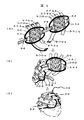
次に、前記光導波路固定部における光導波路の配置形態について、図2により説明する。
【0029】
ここでは、配置形態2−1および配置形態2−2の基本的構成を示す。図2(a)に示した配置形態2−1は通常用いられる光導波路配置であり、光導波路固定部を生体に固定する場合に、特に問題がない場合に用いる。光導波路は、正方格子の頂点上に配置する。白丸は光照射用の光導波路を配置する位置を表し、黒丸は光検出(集光)用の光導波路を配置する位置を意味する。
【0030】
図2(b)に示した配置形態2−2は、側頭部を計測する際に用いられる光導波路配置である。側頭部を計測する際には、耳があるため正方格子状に光導波路を配置することが難しい。ここでは、耳を避けるため中心の縦軸線が両側の軸線より少し上方(1cm〜2cm)にあげられている。このように配置することで、耳を避けて計測することが可能となる。即ち、光導波路をひし形格子の頂点上に配置する。白丸は光照射用の光導波路を配置する位置を表し、黒丸は光検出(集光)用の光導波路を配置する位置を意味する。
【0031】
両配置形態に共通して、照射用および集光用の光導波路の位置は反転してもかまわない。また、配置形態2−2で計測した信号から画像を再構築する際には、表示画像を配置形態と同じ形状で表示する。
【0032】
次に、生体光計測用プローブの光導波路固定部を頭部へ装着する装着手段及びその装着方法について、図3により説明する。図3の(A)は光導波路固定部を頭部へ装着する面から見た図、(B)はそれを斜め方向から見た図、(C)は頭部装着状態を示した図である。
【0033】
図3(A)に示すように、光導波路固定部3−1および3−2は、光導波路固定部の保持部3−3および3−4によって保持されている。光導波路固定部の保持部3−3及び3−4は、図3(B)に示すように、伸縮性帯または紐3-3-1及び3-3-2及び3-3-3及び3-4-1及び3-4-2及び3-4-3によって構成されており、光導波路固定部の各保持部3−3及び3−4の両端で各伸縮性帯または紐は連結している。
【0034】
上記伸縮性帯または紐は、重量は軽く、また、光導波路の接触状態を容易に確認できるほうが良いため、できる限り細い物がよい。本発明では伸縮性のある布を使用したが、同様の機能を有するものであれば異なる材質を用いても構わない。光導波路固定部保持部の連結部3−5及び3−6は、光導波路固定部の保持部3−3及び3−4を連結する目的で作られている。光導波路固定部保持部の連結部3−5及び3−6は、以下の理由で形状および機能が決定される。
【0035】
第1に、計測対象が生体であるためその大きさには個人差がある。この個人差に対応できるよう、連結の距離が変更できなければならない。本発明では、脱着自在布テープを、光導波路固定部の保持部3−3及び3−4の両端と光導波路固定部保持部の連結部3−5及び3−6の両端に取り付け、頭部周囲長に応じた距離調整を可能とした。
【0036】
第2に、光導波路固定部保持部の連結部3−5及び3−6は、直接被験者の皮膚に接触するため、幅および被験者接触面を考慮する必要がある。被験者皮膚に対して圧力の集中を避けるためには、光導波路固定部の保持部3−3及び3−4を構成する伸縮性帯または紐の様に細ければ良いわけではなく、ある程度の幅を有する必要がある。その幅は、1cmから4cmの間が望ましい。また、光導波路固定部保持部の連結部3−5及び3−6の被験者への接触面は、柔らかな素材でかつ摩擦係数の高い(滑らないように)ものが望ましい。そのための素材として、シリコンラバーやスポンジをあげることができる。勿論、同等の機能を有すれば、他の素材でも構わない。
【0037】
光導波路固定部3−1及び3−2が小さい場合には、上記説明した構成要素による装着が可能である。しかし、光導波路固定部3−1及び3−2が大きい場合には、以下に説明する補助的保持部を用い、各光導波路に均一な圧力を与える必要がある。
【0038】
本発明では、図3(A)に示すように、補助的保持部3-7-1-a〜3-7-5-a及び3-7-1-b〜3-7-5-bを取り付けてある。各補助的保持部3-7-1-a〜3-7-5-a及び3-7-1-b〜3-7-5-bの先端には、脱着自在布テープを取り付けてあり、例えば補助的保持部3-7-1-aと補助的保持部3-7-1bを被験者頭部形状に応じて長さを調整して連結する。他の補助的保持部も同様に、a−b間で長さを調整して連結する。各各補助的保持部3-7-1-a〜3-7-5-a及び3-7-1-b〜3-7-5-bの素材は、できるだけ細い伸縮性帯または紐を用いる。
【0039】
また、図3(C)に示すように、光導波路3−8の様に、全ての光導波路ガイドに光導波路は挿入されている。装着の手順は、図3において、(A)→(B)→(C)の順序で行うことで、簡便に装着することができる。
【0040】
この光導波路固定部の保持部の特徴を、以下に列挙する。
1) 簡便かつ素早く装着できる。
2) さまざまな被験者計測部位の形状及びサイズに適応できる。
3) 被験者皮膚に対して、均一かつ適切な圧力を加えることができる。
【0041】
計測部位に応じて、光導波路固定部の保持部の形状は様々に変わるが、前記光導波路固定部の保持部を構成する要点は、以下のとおりである。
1) 複数に分割し、装着時に連結する。
2) 連結部分に、長さ調整を行えるようにする。
3) 伸縮性の帯または紐を用いる。
【0042】
上記1)及び2)を実現するためには、例えば、脱着自在布テープを用い、3)を実現するためには、伸縮性布やゴム等を用いる。
【0043】
次に、図4は、生体光計測用プローブの光導波路固定部の断面図を示す。光導波路は、基本的には、光導波路部4−1−1及び光導波路保持部キャップ4−1−2及び光導波路保持部4−1−3から構成される。光導波路部4−1−1は、図に示すように光導波路保持部4−1−3を貫通して、その先端部が出ている。先端部は矢印で示すように任意の圧力(弾性体が光導波路保持部4−1−3に配置されている)で上下に可動する。この可動により、被験者生体表面へ適切な圧力で光導波路先端部を密着する。
【0044】
光導波路保持部キャップ4−1−2及び光導波路保持部4−1−3は、それぞれの外壁面及び内壁面に切られたネジで連結される。
【0045】
光導波路保持部キャップ4−1−2と光導波路保持部4−1−3の間には、図3中の光導波路固定部保持部3−3または3−4を構成する伸縮性帯または紐4−2が挟まることで固定されている。伸縮性帯または紐が非常に細い場合には、リング形状にして上記と同様に挟めたり、光導波路保持部または光導波路ガイドに固定部を設けて固定しても構わない。
【0046】
接合部材4−3は、プラスチックでできたリング形状のものであり、光導波路ガイドを構成するクッション部材4−4と光導波路を構成する光導波路保持部4−1−3を接合している。接合部材4−3の下面は、接着剤でクッション部材4−4と接合している。また、接合部材4−3の内部に空けられた穴が、図に示すように光導波路保持部4−1−3の溝にはめ込まれている。光導波路及び光導波路ガイドを1体成型、または、接着して製作できる場合には、この接合部材4−3は不要となる。クッション部材4−4は、図中に示すように、矢印方向(上下)に可動であり、光導波路固定部保持部を構成する伸縮性帯または紐4−2によって適切な圧力が加えられる。
【0047】
光減衰フィルター4−5は、光照射用の光導波路先端部を覆うように取り付けられることがある。
【0048】
各光導波路ガイド及び光導波路は、被験者接触部材4−6で連結されている。この被験者接触部材4−6は、薄ければ薄いほど良く、黒色であり、被験者組織に対して摩擦係数が高く、光導波路部4−1−1のほぼ先端に配置されている。さらに、汗発散性や通気性が高ければ、さらに快適性を増すことができる。
【0049】
上述した実施例では、乳幼児頭部計測を主体にして説明してきたが、本発明は、乳幼児頭部計測に限定されるものではない。即ち、構成要素を保持しつつサイズや光導波路の配置を変更することにより、大人頭部の計測や、頭部以外の筋肉内の計測等にも用いることは可能である。
【0050】
以上のように、本発明は、生体との接触面に柔軟性、摩擦係数が高い部材を配置し、さらに、接触面に均等に圧力を加えるため光照射手段および集光手段を伸縮性材料によって固定する、2重構造化をはかることにより、曲率が大きく、動きの大きい生体部位に対する生体光計測を実現可能にしたものである。
【0051】
【発明の効果】
本発明によれば、大きな曲率を有する生体表面に対し、簡便に装着可能な生体光計測用プローブによって、これまで計測が困難であった新生児・乳幼児の頭部や腕などの運動部位の計測が可能となった。また、本発明は、生体光計測装置の応用範囲の拡大につながり、産業上の寄与が大きい。特に、脳機能の発達過程の理解は、教育など人間社会へ大きな影響を与える分野に寄与する。
【図面の簡単な説明】
【図1】本発明に基づく生体光計測用プローブの光導波路固定部の一実施例を示す図。
【図2】本発明における光導波路の配置形態の構成例を示す図。
【図3】本発明に基づく生体光計測用プローブの装着手段及びその装着方法を説明する図。
【図4】本発明に基づく生体光計測用プローブの光導波路固定部の断面図。
【符号の説明】
1-1-1-a:光導波路保持部、1-1-1-b:光導波路保持部、1-1-2-a:光導波路部、 1-1-2-b:光導波路部、1−2:光導波路ガイド、1−3:接合部材、1−4:クッション部材、1−5:被験者接触部材、1−6:孔、1−7:形状保持部材、1−8:光減衰フィルター、2−1:配置形態、2−2:配置形態、3−1:光導波路固定部、 3−2:光導波路固定部、 3−3:光導波路固定部保持部、3-3-1:伸縮性帯または紐、3-3-2:伸縮性帯または紐、3-3-3:伸縮性帯または紐、3−4:光導波路固定部保持部、3-4-1:伸縮性帯または紐、3-4-2:伸縮性帯または紐、3-4-3:伸縮性帯または紐、3−5:光導波路固定部保持部連結部、3−6:光導波路固定部保持部連結部、3-7-1-a〜3-7-5-a:補助的保持部、3-7-1-b〜3-7-5-b: 補助的保持部、3−8:光導波路、4-1-1:光導波路部、 4-1-2:光導波路保持部キャップ、4-1-3:光導波路保持部、 4-1-1:光導波路部、4−2:伸縮性帯または紐、4−3:接合部材、4−4:クッション部材、4−5:光減衰フィルター、4−6:被験者接触部材。[0001]
BACKGROUND OF THE INVENTION
The present invention relates to a living body light measuring apparatus that measures light of a metabolite inside a living body using light.
[0002]
[Prior art]
In living body measurement using light, an apparatus for measuring a living body function using visible to near-infrared light is disclosed in, for example, Japanese Patent Application Laid-Open No. 57-115232 or Japanese Patent Application Laid-Open No. 63-275323. Furthermore, an invention (optical topography) relating to an image measurement technique for brain function by applying this measurement principle is proposed in Japanese Patent Laid-Open No. 9-98972.
[0003]
These use light waveguide means represented by an optical fiber or the like, and irradiate light on a living body and scatter light within the living body at a position away from several mm to several centimeters (hereinafter abbreviated as living body scattered light). Condensation measurement. Based on the measured intensity of the scattered light from the living body, the concentration of the light-absorbing substance in the living body or a value corresponding to the concentration, such as oxyhemoglobin and reduced hemoglobin, is obtained. When obtaining the light-absorbing substance concentration or a value corresponding to the concentration, the light-absorbing characteristic of the target light-absorbing substance corresponding to the wavelength of the irradiated light is used. Generally, when measuring a deep part of a living body, light having a wavelength within a range of 650 nm to 1300 nm having high biological permeability is used.
[0004]
[Problems to be solved by the invention]
In living body light measurement, a means for irradiating light (hereinafter referred to as a light irradiating means) to an object to be inspected (living body) and a means for condensing passing light propagating inside the living body (hereinafter referred to as a condensing means). )have. These light irradiating means and condensing means often include optical waveguides represented by optical fibers or optical fiber bundles. In addition, a set of optical waveguides for light irradiation and light collection is a minimum unit (hereinafter abbreviated as a light irradiation light collection pair) representing one measurement position. An apparatus for measuring a living body image by setting a plurality of minimum units is proposed in Japanese Patent Laid-Open No. 9-98972.
[0005]
Here, the distance between the irradiation position of the light irradiation condensing pair and the condensing position (hereinafter referred to as the distance between the light irradiation condensing pair) varies depending on the width or depth of the region to be measured. Therefore, in Japanese Patent Laid-Open No. 9-98972, the optical waveguide for light irradiation and the optical waveguide for light collection are alternately arranged on the apex of the square lattice so that the distance between the respective light irradiation and condensing pairs becomes equal. The arrangement form to arrange is proposed. If this arrangement is used, one optical waveguide is shared by a plurality of light irradiation and condensing pairs, so that image measurement can be performed with a small number of optical waveguides. Therefore, the optical waveguide can be attached to the living body in a short time.
[0006]
However, this arrangement is easy to apply to a narrow area of the living body that can be approximated by the plane of the living body (for example, about 15 cm square in the case of the head), but is difficult to apply to an area with a large curvature. . In particular, the head shape of newborns and infants has a large curvature, and there are large individual differences. In addition, when measuring newborns, infants, etc., it was impossible for an adult to assume that the subject could not wait quietly, so the displacement of the probe due to movement had to be suppressed. Problems arise.
[0007]
In particular, the means for measuring the brain function of newborns and infants has so far been limited to electroencephalographs. However, the electroencephalograph does not have a very high spatial resolution, and it is difficult to separate information on the cerebral cortex on the brain stem and brain surface in the central part of the brain. On the other hand, the brain function measurement method based on optical measurement is capable of non-invasive measurement of the cerebral cortex that is strongly linked to the higher brain function developed especially in humans. It was expected to be an effective method.
[0008]
However, although known to be effective in principle, a fixture (probe) for fixing a waveguide for irradiating and collecting light has not been developed so far.
[0009]
Therefore, in order to construct a practical optical waveguide probe for measuring biological light for newborns and infants, the following points are required. Listed below.
(1) Flexibility:
The biological optical measurement probe to be used must be able to be flexibly adapted to a biological surface having a curvature.
(2) Ability to maintain distance between waveguides for incident detection:
The biological light measurement probe used has a distance between the waveguides for detection of incidents (to be exact, the distance between the tip of the light irradiating optical waveguide and the tip of the condensing optical waveguide, with respect to shapes having individual differences. However, for the sake of convenience, the distance between incident detections will not be changed beyond a predetermined allowable range.
(3) Body motion followability:
The biological optical measurement probe used should not be displaced even if it involves a certain amount of movement.
(4) Adhesion visibility:
The living body optical measurement probe to be used must have high visibility and can easily control the close contact state so that the close contact between the optical waveguide and the living body surface can be confirmed.
(5) Comfort:
For subjects with low adaptability to environmental changes, such as newborns and infants, the head etc. must not be completely covered from the viewpoint of temperature changes.
(6) Pressure dispersibility:
In the case of a subject with a sensitive head, such as a newborn or infant, do not apply high pressure to one point.
(7) Shape retention:
In order to reduce the inconvenience given to the subject, it is necessary to attach the probe in a short time, so that the shape can be easily changed and the basic shape must be maintained.
(8) Wearability:
For the same reason as the problem 7, a means for easily fixing the probe is necessary.
(9) Shape / size adaptability of fixing means:
The means for fixing needs to be adaptable to the head shape of the subject.
(10) Pressurization of fixing means:
The means for fixing needs to be able to apply an appropriate pressure.
[0010]
The present invention has been made in view of the above points, and an object of the present invention is to provide a living body light measuring apparatus including a probe that has a large curvature and can be attached to a moving living body part in living body light measurement. And
[0011]
[Means for Solving the Problems]
In order to achieve the above object, in the present invention, the incident optical waveguide and the condensing optical waveguide tip are connected by a flexible material. However, this flexible material is preferably a material that does not stretch so much that the distance between incident detections does not change. For example, silicon rubber is suitable.
[0012]
Further, in the present invention, in order to achieve the above object, a material having a high coefficient of friction is disposed on the surface in contact with the living body, and each light guide is made of a stretchable material in order to apply an appropriate pressure to each waveguide. The connection was made at 1 to 2 cm from the tip of the waveguide.
[0013]
Furthermore, in the present invention, in order to achieve the above object, in the material connecting the optical waveguide tip and the material connecting 1 to 2 cm from the optical waveguide tip, a portion unnecessary for the connection is removed to ensure visibility. did. Moreover, the control of the adhesion of the optical waveguide to the living body could be easily solved by connecting at a distance of 1 to 2 cm from the tip of each optical waveguide with a stretchable material.
[0014]
As described above, the present invention provides a light irradiating means for irradiating the object to be inspected with light through the optical waveguide, and the light irradiated from the light irradiating means and propagating through the inside of the object to be inspected via the optical waveguide. In the living body light measuring apparatus that measures a metabolite inside the subject using a probe that has a light collecting means for collecting light, the probe is used for the light irradiation means and for the light collecting means. As described above, there is provided a living body light measuring device having a plurality of optical waveguides, and a portion in contact with the object to be inspected is composed of at least one surface structure member.
[0015]
Further, according to the present invention, in the configuration described above, a distance between the optical waveguides is within a predetermined allowable range, with a tip portion of each optical waveguide of the light irradiating unit and the condensing unit contacting a surface to be inspected. The living body light measuring device is provided so as to be supported by the above.
[0016]
Moreover, this invention provides the biological light measuring device characterized by the part which contacts the said to-be-inspected object being comprised in the said structure by the member of the several surface structure which divided | segmented.
[0017]
Furthermore, the present invention provides a light irradiating means for irradiating light to the object to be inspected via the optical waveguide, and a light collecting means for collecting the light irradiated from the light irradiating means and propagating through the inside of the object to be inspected via the optical waveguide. In the living body optical measuring device that measures a metabolite inside the subject using a probe provided with a means, the probe is a member having a plurality of surface structures in which a portion that contacts the subject is divided A plurality of optical waveguides for light irradiation and a plurality of optical waveguides for light collection detection are provided on each member of the surface structure, and between the members of the surface structure via a flexible member The living body light measuring device is characterized by being connected to each other.
[0018]
DETAILED DESCRIPTION OF THE INVENTION
Hereinafter, an embodiment of the present invention will be described.
[0019]
FIG. 1 shows an optical waveguide fixing portion of a biological light measurement probe based on this embodiment. FIG. 2 shows an arrangement form of the optical waveguide. FIG. 3 shows a mounting means for mounting the optical waveguide fixing portion on the head and a mounting method thereof.
[0020]
First, a description will be given regarding FIG. Since it is basically composed of repeated patterns, only the basic configuration will be described. An optical waveguide for irradiating light from a light source to an object to be inspected is composed of an optical waveguide holding unit 1-1-1-1a and an optical waveguide unit 1-1-2-a. This optical waveguide is inserted into the optical waveguide guide 1-2. In the figure, an optical waveguide constituted by an optical waveguide holding section 1-1-1-2b and an optical waveguide section 1-1-2-b is provided in an optical waveguide guide 1-2 of an adjacent optical waveguide for condensing. Indicates a state where is already inserted. In this figure, one optical waveguide before insertion and one after insertion are shown, but the optical waveguide is inserted into all the optical waveguide guides in FIG. In the present embodiment, the case where the number of optical waveguides in the optical waveguide fixing portion is nine is shown, but it is needless to say that the present invention is not limited to this example.
[0021]
The optical waveguide is bonded, screwed, integrally processed, or mechanically fixed to the optical waveguide guide 1-2. The joining member 1-3 that joins the optical waveguide fixing guide 1-2 and the cushion member 1-4 is made of a flexible plastic or the like, and is fitted in a groove formed in the optical waveguide guide 1-2. For the cushion member 1-4, for example, a material having flexibility and elasticity such as sponge and silicon is used.
[0022]
Further, the bottom surface of the joining member 1-3 (the surface in contact with the cushion member 1-4) is joined to the cushion member member 1-4 with an adhesive or the like. The cushion member member 1-4 is bonded to the subject contact member 1-5 with an adhesive or the like. The subject contact member 1-5 is highly compatible with the subject tissue from the viewpoint of safety, has a sufficient coefficient of friction so as not to be displaced by body movement, and reflects light on the surface of the subject contact member 1-5. In order to suppress this, it is necessary that the wavelength of the light source is not transmitted or reflected (for example, black) and is soft enough to flexibly handle an arbitrary shape.
[0023]
Further, a hole (opening) 1-6 is provided in order to enhance the air permeability and to confirm the contact condition of the optical waveguide. Examples of the material that satisfies these conditions include silicon rubber and cloth, but other materials that satisfy the same condition may be used.
[0024]
The shape holding member 1-7 is fixed to the subject contact member 1-5 so as to connect the optical waveguide guides 1-2 to each other in order to hold the entire shape. The shape holding member 1-7 is made of a linear metal or plastic. There may be no case where the subject contact member 1-5 has sufficient rigidity or the subject contact portion has a large curvature.
[0025]
The light attenuation filter 1-8 is made of a soft material such as vinyl. When the intensity of the light source is strong, or when the intensity of the light irradiation light source cannot be adjusted, the light attenuation filter 1-8 is attached so as to cover the tip of the optical waveguide for light irradiation. It doesn't matter.
[0026]
The tip of the optical waveguide is fixed at a position slightly recessed upward from the surface of the subject contact member 1-5 that contacts the subject. For example, about 0.5 mm to 4 mm is desirable.
[0027]
The characteristics of this optical waveguide fixing part are listed below.
1) Since the connected members are made of a very soft material, it can be adapted to any shape.
2) Since they are connected at the tip of the optical waveguide, the distance between the optical waveguides (actually the path) does not change at the subject contact portion. This contributes to obtaining a spatially uniform signal because the infiltration degree of light in each measurement unit is constant.
3) Since the connected members have an appropriate coefficient of friction, they do not deviate even when body movement occurs.
4) A hole is formed in an unnecessary portion of the connected members, and the visibility for confirming the adhesion of the optical waveguide is high.
5) A hole is formed in an unnecessary portion of the connected members, and ventilation is possible so that the subject's skin does not get steamed, and comfort is high.
6) Only the distal end of the optical waveguide does not apply pressure to the subject's skin surface, and pressure can be applied in a wide area, and since pressure is applied by the cushion member, the pain given to the subject is extremely small. .
[0028]
Next, the arrangement of the optical waveguides in the optical waveguide fixing part will be described with reference to FIG.
[0029]
Here, basic configurations of the arrangement form 2-1 and the arrangement form 2-2 are shown. The arrangement form 2-1 shown in FIG. 2A is an optical waveguide arrangement that is normally used, and is used when there is no particular problem when the optical waveguide fixing portion is fixed to a living body. The optical waveguide is disposed on the apex of the square lattice. A white circle represents a position where an optical waveguide for light irradiation is arranged, and a black circle means a position where an optical waveguide for light detection (condensation) is arranged.
[0030]
Arrangement form 2-2 shown in FIG. 2B is an optical waveguide arrangement used when measuring the temporal region. When measuring the temporal region, it is difficult to arrange the optical waveguides in a square lattice because there are ears. Here, in order to avoid the ears, the central vertical axis is slightly above (1 cm to 2 cm) above the axial lines on both sides. By arranging in this way, it is possible to measure while avoiding the ears. That is, the optical waveguide is disposed on the apex of the rhombus lattice. A white circle represents a position where an optical waveguide for light irradiation is arranged, and a black circle means a position where an optical waveguide for light detection (condensation) is arranged.
[0031]
In common with both arrangement forms, the positions of the irradiation and condensing optical waveguides may be reversed. Further, when reconstructing an image from the signal measured in the arrangement form 2-2, the display image is displayed in the same shape as the arrangement form.
[0032]
Next, a mounting means for mounting the optical waveguide fixing portion of the biological light measurement probe on the head and a mounting method thereof will be described with reference to FIG. 3A is a view of the optical waveguide fixing portion as viewed from the surface where it is mounted on the head, FIG. 3B is a view of the optical waveguide fixing portion viewed from an oblique direction, and FIG. .
[0033]
As shown in FIG. 3A, the optical waveguide fixing portions 3-1 and 3-2 are held by holding portions 3-3 and 3-4 of the optical waveguide fixing portion. As shown in FIG. 3 (B), the holding portions 3-3 and 3-4 of the optical waveguide fixing portion are stretchable bands or strings 3-3-1 and 3-3-3 and 3-3-3 and 3 -4-1, 3-4-2, and 3-4-3, and each elastic band or string is connected at both ends of each holding portion 3-3 and 3-4 of the optical waveguide fixing portion. Yes.
[0034]
The elastic band or string is light in weight, and it is desirable that the contact state of the optical waveguide can be easily confirmed. In the present invention, a stretchable cloth is used, but different materials may be used as long as they have similar functions. The connecting portions 3-5 and 3-6 of the optical waveguide fixing portion holding portion are formed for the purpose of connecting the holding portions 3-3 and 3-4 of the optical waveguide fixing portion. The shapes and functions of the connecting portions 3-5 and 3-6 of the optical waveguide fixing portion holding portion are determined for the following reason.
[0035]
First, since the measurement target is a living body, there are individual differences in the size. In order to cope with this individual difference, the distance of the connection must be changeable. In the present invention, the removable cloth tape is attached to both ends of the holding portions 3-3 and 3-4 of the optical waveguide fixing portion and both ends of the connecting portions 3-5 and 3-6 of the optical waveguide fixing portion holding portion. The distance can be adjusted according to the perimeter.
[0036]
Second, since the connecting portions 3-5 and 3-6 of the optical waveguide fixing portion holding portion directly contact the skin of the subject, it is necessary to consider the width and the subject contact surface. In order to avoid the concentration of pressure on the subject's skin, it does not have to be as thin as the elastic band or string constituting the holding portions 3-3 and 3-4 of the optical waveguide fixing portion, and a certain width It is necessary to have. The width is preferably between 1 cm and 4 cm. In addition, the contact surface of the connecting portions 3-5 and 3-6 of the optical waveguide fixing portion holding portion to the subject is preferably a soft material and a high friction coefficient (so as not to slip). For this purpose, silicon rubber or sponge can be used. Of course, other materials may be used as long as they have equivalent functions.
[0037]
When the optical waveguide fixing portions 3-1 and 3-2 are small, the above-described components can be attached. However, when the optical waveguide fixing portions 3-1 and 3-2 are large, it is necessary to apply a uniform pressure to each optical waveguide using an auxiliary holding portion described below.
[0038]
In the present invention, as shown in FIG. 3 (A), the auxiliary holding portions 3-7-1-a to 3-7-5-a and 3-7-1-b to 3-7-5-b are provided. It is attached. Removable cloth tapes are attached to the tips of the auxiliary holding portions 3-7-1-a to 3-7-5-a and 3-7-1-b to 3-7-5-b, For example, the auxiliary holding unit 3-7-1-a and the auxiliary holding unit 3-7-1b are connected by adjusting the length according to the subject head shape. Similarly, the other auxiliary holding portions are connected by adjusting the length between a and b. The material of each auxiliary holding portion 3-7-1-a to 3-7-5-a and 3-7-1-b to 3-7-5-b should use an elastic band or string as thin as possible. .
[0039]
Further, as shown in FIG. 3C, the optical waveguide is inserted into all the optical waveguide guides as in the optical waveguide 3-8. The mounting procedure can be easily performed by performing the sequence of (A) → (B) → (C) in FIG. 3.
[0040]
The characteristics of the holding part of the optical waveguide fixing part are listed below.
1) Easy and quick to wear.
2) Adaptable to various subject measurement site shapes and sizes.
3) A uniform and appropriate pressure can be applied to the subject skin.
[0041]
Although the shape of the holding part of the optical waveguide fixing part varies depending on the measurement site, the main points constituting the holding part of the optical waveguide fixing part are as follows.
1) Divide into multiple parts and connect them when installed.
2) Adjust the length of the connecting part.
3) Use elastic bands or strings.
[0042]
In order to realize the above 1) and 2), for example, a removable cloth tape is used, and in order to realize 3), an elastic cloth or rubber is used.
[0043]
Next, FIG. 4 shows a cross-sectional view of the optical waveguide fixing portion of the biological light measurement probe. The optical waveguide basically includes an optical waveguide section 4-1-1, an optical waveguide holding section cap 4-1-2, and an optical waveguide holding section 4-1-3. As shown in the drawing, the optical waveguide portion 4-1-1 penetrates the optical waveguide holding portion 4-1-3, and the tip portion thereof protrudes. The tip part moves up and down with an arbitrary pressure (an elastic body is disposed in the optical waveguide holding part 4-1-3) as indicated by an arrow. By this movement, the tip of the optical waveguide is brought into close contact with the subject's living body surface with an appropriate pressure.
[0044]
The optical waveguide holding portion cap 4-1-2 and the optical waveguide holding portion 4-1-3 are connected to each other by screws cut on the outer wall surface and the inner wall surface.
[0045]
Between the optical waveguide holding part cap 4-1-2 and the optical waveguide holding part 4-1-3, an elastic band or string constituting the optical waveguide fixing part holding part 3-3 or 3-4 in FIG. It is fixed by pinching 4-2. If the elastic band or string is very thin, it may be ring-shaped and sandwiched in the same manner as described above, or may be fixed by providing a fixing portion on the optical waveguide holding portion or the optical waveguide guide.
[0046]
The joining member 4-3 has a ring shape made of plastic, and joins the cushion member 4-4 constituting the optical waveguide guide and the optical waveguide holding portion 4-1-3 constituting the optical waveguide. The lower surface of the bonding member 4-3 is bonded to the cushion member 4-4 with an adhesive. Moreover, the hole vacated inside the joining member 4-3 is inserted in the groove | channel of the optical waveguide holding | maintenance part 4-1-3 as shown in a figure. If the optical waveguide and the optical waveguide guide can be molded or bonded together, this joining member 4-3 is not necessary. As shown in the drawing, the cushion member 4-4 is movable in the direction of the arrow (up and down), and appropriate pressure is applied by an elastic band or string 4-2 that constitutes the optical waveguide fixing portion holding portion.
[0047]
The light attenuating filter 4-5 may be attached so as to cover the front end of the light irradiation optical waveguide.
[0048]
Each optical waveguide guide and the optical waveguide are connected by a subject contact member 4-6. The subject contact member 4-6 is better as it is thinner, is black, has a high coefficient of friction with respect to the subject tissue, and is disposed almost at the tip of the optical waveguide section 4-1-1. Furthermore, if sweat perspiration and breathability are high, comfort can be further increased.
[0049]
In the above-described embodiments, description has been made mainly on infant head measurement, but the present invention is not limited to infant head measurement. That is, by changing the size and the arrangement of the optical waveguide while holding the constituent elements, it can be used for measurement of an adult head, measurement in muscles other than the head, and the like.
[0050]
As described above, in the present invention, a member having a high flexibility and a high friction coefficient is arranged on the contact surface with the living body, and the light irradiation means and the light collecting means are made of a stretchable material in order to apply pressure evenly to the contact surface. By fixing the double structure, it is possible to realize living body light measurement for a living body part having a large curvature and a large movement.
[0051]
【The invention's effect】
According to the present invention, it is possible to measure a movement part such as a head or an arm of a newborn infant or an infant that has been difficult to measure with a biological optical measurement probe that can be easily mounted on a biological surface having a large curvature. It has become possible. Moreover, this invention leads to the expansion of the application range of a biological light measuring device, and its industrial contribution is great. In particular, understanding the developmental process of brain functions contributes to fields that have a major impact on human society, such as education.
[Brief description of the drawings]
FIG. 1 is a diagram showing an embodiment of an optical waveguide fixing part of a biological light measurement probe according to the present invention.
FIG. 2 is a view showing a configuration example of an optical waveguide arrangement according to the present invention.
FIG. 3 is a view for explaining the means for attaching the biological optical measurement probe and the method for attaching the same according to the present invention.
FIG. 4 is a cross-sectional view of an optical waveguide fixing portion of a biological light measurement probe according to the present invention.
[Explanation of symbols]
1-1-1-a: optical waveguide holding section, 1-1-b: optical waveguide holding section, 1-1-2-a: optical waveguide section, 1-1-2-b: optical waveguide section, 1-2: Optical waveguide guide, 1-3: Bonding member, 1-4: Cushion member, 1-5: Subject contact member, 1-6: Hole, 1-7: Shape holding member, 1-8: Light attenuation Filter, 2-1: Arrangement form, 2-2: Arrangement form, 3-1: Optical waveguide fixing part, 3-2: Optical waveguide fixing part, 3-3: Optical waveguide fixing part holding part, 3-3-1 : Stretchable band or string, 3-3-2: Stretchable band or string, 3-3-3: Stretchable band or string, 3-4: Optical waveguide fixing part holding part, 3-4-1: Stretchable characteristic Band or string, 3-4-2: Elastic band or string, 3-4-3: Elastic band or string, 3-5: Optical waveguide fixing part holding part connection part, 3-6: Optical waveguide fixing part holding Part connection part, 3-7-1-a to 3-7-5-a: auxiliary protection Part, 3-7-1-b to 3-7-5-b: auxiliary holding part, 3-8: optical waveguide, 4-1-1: optical waveguide part, 4-1-2: optical waveguide holding part Cap, 4-1-3: Optical waveguide holding part, 4-1-1: Optical waveguide part, 4-2: Elastic band or string, 4-3: Joining member, 4-4: Cushion member, 4-5 : Light attenuation filter, 4-6: Subject contact member.
Claims (2)
前記プローブは、複数の前記光導波路を保持する複数の光導波路保持部と、被験者接触部材とを有し、
前記被験者接触部材は、前記被検査体に接触する部分が少なくとも1つの面構造の部材で構成されており、前記複数の光導波路保持部を固定し、
前記光照射手段および前記集光手段は、ひし形格子形状の頂点の位置に交互に在るよう配置構成され、
かつ、前記光照射手段および前記集光手段は、前記被検査体の側頭部を計測する際に用いられ、前記ひし形格子形状の中心の縦軸線が、前記中心の縦軸線の両側の軸線より上方にあげられていることを特徴とする生体光計測装置。A light irradiating means for irradiating the object to be inspected with light through the optical waveguide; and a light collecting means for collecting the light irradiated from the light irradiating means and propagating through the inside of the object to be inspected through the optical waveguide In the living body optical measurement device adapted to measure a metabolite inside the test subject using a probe comprising
The probe has a plurality of optical waveguide holding portions that hold the plurality of optical waveguides, and a subject contact member,
The subject contact member is composed of a member having at least one surface structure in contact with the subject to be inspected, and fixes the plurality of optical waveguide holding portions,
The light irradiating means and the light collecting means are arranged to be alternately arranged at the positions of the apexes of the rhombus lattice shape ,
The light irradiating means and the light collecting means are used when measuring the temporal region of the object to be inspected, and the longitudinal axis of the center of the rhombus lattice shape is more than the axes on both sides of the longitudinal axis of the center. A biological light measurement device characterized by being raised upward .
Priority Applications (4)
| Application Number | Priority Date | Filing Date | Title |
|---|---|---|---|
| JP2001102806A JP4090699B2 (en) | 2001-04-02 | 2001-04-02 | Biological light measurement device |
| US10/450,895 US7139600B2 (en) | 2001-04-02 | 2002-01-18 | Biophotometer |
| PCT/JP2002/000325 WO2002080777A1 (en) | 2001-04-02 | 2002-01-18 | Biophotometer |
| EP02710312A EP1374778A4 (en) | 2001-04-02 | 2002-01-18 | Biophotometer |
Applications Claiming Priority (1)
| Application Number | Priority Date | Filing Date | Title |
|---|---|---|---|
| JP2001102806A JP4090699B2 (en) | 2001-04-02 | 2001-04-02 | Biological light measurement device |
Publications (3)
| Publication Number | Publication Date |
|---|---|
| JP2002291751A JP2002291751A (en) | 2002-10-08 |
| JP2002291751A5 JP2002291751A5 (en) | 2005-06-16 |
| JP4090699B2 true JP4090699B2 (en) | 2008-05-28 |
Family
ID=18955953
Family Applications (1)
| Application Number | Title | Priority Date | Filing Date |
|---|---|---|---|
| JP2001102806A Expired - Fee Related JP4090699B2 (en) | 2001-04-02 | 2001-04-02 | Biological light measurement device |
Country Status (4)
| Country | Link |
|---|---|
| US (1) | US7139600B2 (en) |
| EP (1) | EP1374778A4 (en) |
| JP (1) | JP4090699B2 (en) |
| WO (1) | WO2002080777A1 (en) |
Cited By (1)
| Publication number | Priority date | Publication date | Assignee | Title |
|---|---|---|---|---|
| JP2016067482A (en) * | 2014-09-29 | 2016-05-09 | 株式会社日立メディコ | Optical measurement probe fixture and biological optical measurement apparatus with the same |
Families Citing this family (31)
| Publication number | Priority date | Publication date | Assignee | Title |
|---|---|---|---|---|
| JP2002355246A (en) * | 2001-05-30 | 2002-12-10 | Hitachi Medical Corp | Accessory for biological light measurement and biological light meter |
| JP4489385B2 (en) | 2002-12-12 | 2010-06-23 | 株式会社日立メディコ | Measuring probe and biological light measuring device |
| JP4236950B2 (en) * | 2003-02-13 | 2009-03-11 | シスメックス株式会社 | Non-invasive living body measurement device |
| JP4699213B2 (en) * | 2003-12-02 | 2011-06-08 | 株式会社日立メディコ | Probe device for biological light measurement device |
| JP4543774B2 (en) * | 2004-06-23 | 2010-09-15 | 株式会社日立製作所 | Biological light measurement device |
| JP4625809B2 (en) * | 2004-07-20 | 2011-02-02 | 俊徳 加藤 | Biological function diagnostic apparatus, biological function diagnostic method, biological probe, biological probe mounting tool, biological probe support tool, and biological probe mounting support tool |
| JP4118871B2 (en) * | 2004-12-03 | 2008-07-16 | 株式会社日立製作所 | Bio-light measurement probe and bio-light measurement apparatus using the same |
| EP3095379A1 (en) | 2005-04-15 | 2016-11-23 | Surgisense Corporation | Surgical instruments with sensors for detecting tissue properties, and systems using such instruments |
| WO2006123457A1 (en) * | 2005-05-18 | 2006-11-23 | Hitachi Medical Corporation | Optical bioinstrumentation device |
| JP4937916B2 (en) * | 2005-08-29 | 2012-05-23 | 株式会社日立メディコ | Probe holder mounting tool for biological optical measurement device |
| JP4835428B2 (en) * | 2006-12-27 | 2011-12-14 | 株式会社日立製作所 | Probe device |
| JP4888150B2 (en) * | 2007-02-20 | 2012-02-29 | 株式会社日立製作所 | Probe device |
| JP4948326B2 (en) * | 2007-08-21 | 2012-06-06 | 株式会社日立製作所 | Head mounted holder for biological light measurement |
| JP5023921B2 (en) * | 2007-09-26 | 2012-09-12 | 株式会社島津製作所 | Holder and optical biometric apparatus used therefor |
| DE102007046694A1 (en) * | 2007-09-28 | 2009-04-09 | Raumedic Ag | Sensor system for measuring, transmitting, processing and displaying a brain parameter |
| JP4991468B2 (en) | 2007-09-28 | 2012-08-01 | 株式会社日立製作所 | Probe device |
| JP5481032B2 (en) * | 2008-02-20 | 2014-04-23 | 株式会社日立製作所 | Bio-light measurement probe and bio-light measurement apparatus using the same |
| JP4957595B2 (en) * | 2008-03-12 | 2012-06-20 | 株式会社島津製作所 | Absorbance origin standard and method of use |
| JP5216387B2 (en) * | 2008-03-31 | 2013-06-19 | 株式会社日立製作所 | Probe device |
| US8521244B2 (en) * | 2009-09-16 | 2013-08-27 | Analogic Corporation | Physiological parameter monitoring apparatus |
| CN103096813B (en) * | 2010-07-16 | 2015-01-07 | 株式会社岛津制作所 | Holder and light measurement device employing same |
| CN103458801B (en) * | 2011-04-11 | 2015-06-03 | 株式会社岛津制作所 | Holder set and brain function measuring device using same |
| WO2013179406A1 (en) * | 2012-05-30 | 2013-12-05 | 株式会社島津製作所 | Holder and optical biometric device using same |
| JP2017023455A (en) * | 2015-07-23 | 2017-02-02 | 株式会社アドバンテスト | Near-infrared bioinstrumentation apparatus and probe thereof |
| CN106725306B (en) * | 2016-11-28 | 2019-06-25 | 武汉资联虹康科技股份有限公司 | The elastic probe of near infrared spectrum cerebral function imaging device |
| WO2018162808A1 (en) | 2017-01-10 | 2018-09-13 | Braindex S.A.S | Physiological sensor for near-infrared spectroscopy at various depths |
| FR3065869B1 (en) * | 2017-05-03 | 2019-06-21 | Braindex S.A.S | PHYSIOLOGICAL SENSOR FOR NEAR-INFRARED SPECTROSCOPY AT DIFFERENT DEPTHS |
| US10955918B1 (en) * | 2018-08-20 | 2021-03-23 | Facebook, Inc. | Head-coupled optode assembly |
| US11301044B1 (en) | 2019-01-28 | 2022-04-12 | Meta Platforms, Inc. | Wearable brain computer interface |
| WO2020183854A1 (en) * | 2019-03-13 | 2020-09-17 | 国立研究開発法人産業技術総合研究所 | Probe holder |
| US11730373B2 (en) | 2020-04-20 | 2023-08-22 | Covidien Lp | Sensor with variable depth interrogation |
Family Cites Families (23)
| Publication number | Priority date | Publication date | Assignee | Title |
|---|---|---|---|---|
| US4227516A (en) * | 1978-12-13 | 1980-10-14 | Meland Bruce C | Apparatus for electrophysiological stimulation |
| US4335710A (en) * | 1980-01-16 | 1982-06-22 | Omnitronics Research Corporation | Device for the induction of specific brain wave patterns |
| JPS57115232A (en) | 1980-07-09 | 1982-07-17 | Deyuuku Univ Inc | Apparatus for measuring metabolic action in internal organ |
| JPS63275323A (en) | 1987-05-08 | 1988-11-14 | Hamamatsu Photonics Kk | Diagnostic apparatus |
| US5090415A (en) * | 1989-02-14 | 1992-02-25 | Hamamatsu Photonics Kabushiki Kaisha | Examination apparatus |
| JPH0481375A (en) | 1990-07-23 | 1992-03-16 | Topy Ind Ltd | Caterpillar vehicle |
| US5123899A (en) * | 1991-01-17 | 1992-06-23 | James Gall | Method and system for altering consciousness |
| JP3142080B2 (en) * | 1992-03-19 | 2001-03-07 | 株式会社日立製作所 | Biological light measurement device |
| US5283521A (en) | 1992-05-26 | 1994-02-01 | International Business Machines Corporation | Method and system for adaptive digital linearization of an output signal from a magnetoresistive head |
| JPH0644510U (en) * | 1992-09-30 | 1994-06-14 | 株式会社島津製作所 | Optical scanning device |
| JP3577335B2 (en) * | 1993-06-02 | 2004-10-13 | 浜松ホトニクス株式会社 | Scattering absorber measurement method and device |
| CA2131950A1 (en) * | 1993-09-16 | 1995-03-17 | Kazumi Masaki | Fm theta-inducing audible sound, and method, device and recorded medium to generate the same |
| US5803909A (en) | 1994-10-06 | 1998-09-08 | Hitachi, Ltd. | Optical system for measuring metabolism in a body and imaging method |
| US5885976A (en) * | 1995-05-08 | 1999-03-23 | Sandyk; Reuven | Methods useful for the treatment of neurological and mental disorders related to deficient serotonin neurotransmission and impaired pineal melatonin functions |
| JPH0998972A (en) | 1995-10-06 | 1997-04-15 | Hitachi Ltd | Measurement equipment of light from living body and image generation method |
| JP3682793B2 (en) | 1995-11-30 | 2005-08-10 | 株式会社日立製作所 | Light scattering device internal imaging device |
| US6240309B1 (en) * | 1995-10-06 | 2001-05-29 | Hitachi, Ltd. | Optical measurement instrument for living body |
| JP3588880B2 (en) | 1995-11-17 | 2004-11-17 | 株式会社日立製作所 | Biological light measurement device |
| GB2311854B (en) * | 1995-11-17 | 2000-03-22 | Hitachi Ltd | Optical measurement instrument for living body |
| JP3593764B2 (en) * | 1995-11-29 | 2004-11-24 | 株式会社日立製作所 | Biological light measurement device |
| US6135944A (en) * | 1997-11-14 | 2000-10-24 | Zebedee Research, Inc. | Method of inducing harmonious states of being |
| JP4484373B2 (en) * | 1999-03-29 | 2010-06-16 | 株式会社日立メディコ | Biological light measurement device |
| US6577884B1 (en) * | 2000-06-19 | 2003-06-10 | The General Hospital Corporation | Detection of stroke events using diffuse optical tomagraphy |
-
2001
- 2001-04-02 JP JP2001102806A patent/JP4090699B2/en not_active Expired - Fee Related
-
2002
- 2002-01-18 EP EP02710312A patent/EP1374778A4/en not_active Withdrawn
- 2002-01-18 WO PCT/JP2002/000325 patent/WO2002080777A1/en active Application Filing
- 2002-01-18 US US10/450,895 patent/US7139600B2/en not_active Expired - Fee Related
Cited By (1)
| Publication number | Priority date | Publication date | Assignee | Title |
|---|---|---|---|---|
| JP2016067482A (en) * | 2014-09-29 | 2016-05-09 | 株式会社日立メディコ | Optical measurement probe fixture and biological optical measurement apparatus with the same |
Also Published As
| Publication number | Publication date |
|---|---|
| EP1374778A4 (en) | 2007-11-14 |
| US20040054271A1 (en) | 2004-03-18 |
| US7139600B2 (en) | 2006-11-21 |
| WO2002080777A1 (en) | 2002-10-17 |
| JP2002291751A (en) | 2002-10-08 |
| EP1374778A1 (en) | 2004-01-02 |
Similar Documents
| Publication | Publication Date | Title |
|---|---|---|
| JP4090699B2 (en) | Biological light measurement device | |
| US7280859B2 (en) | Biological measurement probe, biological optical measurement instrument using the same, and brain function measurement instrument | |
| EP0906052B1 (en) | Optical coupler for an optical examination device | |
| US5337744A (en) | Low noise finger cot probe | |
| US8145288B2 (en) | Medical sensor for reducing signal artifacts and technique for using the same | |
| EP2131738B1 (en) | A method and apparatus for enhancement and quality improvement of analyte measurement signals | |
| JP2011005177A (en) | Implement and method for biological signal measurement | |
| JP2001286449A (en) | Probe device | |
| KR101465046B1 (en) | Medical sensor mounting apparatus | |
| JP4157761B2 (en) | Headgear for living body light measurement and living body light measuring apparatus using the same | |
| JP4961442B2 (en) | Biological measurement probe and biological optical measurement device | |
| US7231241B2 (en) | Probe for optical measurement instrument for living body and optical measurement instrument for living body using the same | |
| JP2002011012A (en) | Bioluminescence measuring insrtument and fixing tool for bioluminescence measurement | |
| JP2004313741A (en) | Optical biological measurement device and its holders | |
| CN105078403B (en) | A kind of measure ocular movemeut amplitude and the multifunctional ruler of pupil diameter and measuring method | |
| CN113288137A (en) | Whole brain area blood oxygen detection probe | |
| JP2005013464A (en) | Biological light measuring instrument | |
| CN113855012A (en) | Near infrared spectrum imaging system and application thereof | |
| CN209153694U (en) | A kind of Fingerstall type oximeter | |
| JP4646980B2 (en) | Biological light measurement device | |
| KR102237602B1 (en) | Apparatus for measuring blood flow | |
| JP5369528B2 (en) | Biological light measurement device and probe for biological light measurement device | |
| CN209450533U (en) | A kind of packaging type repeatability blood oxygen probe | |
| Yamada et al. | Wearable fNIRS device of higher spatial resolution realized by triangular arrangement of dual-purpose optodes | |
| CA2239552C (en) | Optical examination device, system and method |
Legal Events
| Date | Code | Title | Description |
|---|---|---|---|
| A521 | Written amendment |
Free format text: JAPANESE INTERMEDIATE CODE: A523 Effective date: 20040924 |
|
| A621 | Written request for application examination |
Free format text: JAPANESE INTERMEDIATE CODE: A621 Effective date: 20040924 |
|
| A131 | Notification of reasons for refusal |
Free format text: JAPANESE INTERMEDIATE CODE: A131 Effective date: 20070828 |
|
| A521 | Written amendment |
Free format text: JAPANESE INTERMEDIATE CODE: A523 Effective date: 20071023 |
|
| RD02 | Notification of acceptance of power of attorney |
Free format text: JAPANESE INTERMEDIATE CODE: A7422 Effective date: 20071023 |
|
| A02 | Decision of refusal |
Free format text: JAPANESE INTERMEDIATE CODE: A02 Effective date: 20071113 |
|
| A521 | Written amendment |
Free format text: JAPANESE INTERMEDIATE CODE: A523 Effective date: 20071212 |
|
| A911 | Transfer to examiner for re-examination before appeal (zenchi) |
Free format text: JAPANESE INTERMEDIATE CODE: A911 Effective date: 20080128 |
|
| TRDD | Decision of grant or rejection written | ||
| A01 | Written decision to grant a patent or to grant a registration (utility model) |
Free format text: JAPANESE INTERMEDIATE CODE: A01 Effective date: 20080219 |
|
| A61 | First payment of annual fees (during grant procedure) |
Free format text: JAPANESE INTERMEDIATE CODE: A61 Effective date: 20080227 |
|
| R150 | Certificate of patent or registration of utility model |
Free format text: JAPANESE INTERMEDIATE CODE: R150 |
|
| FPAY | Renewal fee payment (event date is renewal date of database) |
Free format text: PAYMENT UNTIL: 20110307 Year of fee payment: 3 |
|
| FPAY | Renewal fee payment (event date is renewal date of database) |
Free format text: PAYMENT UNTIL: 20110307 Year of fee payment: 3 |
|
| FPAY | Renewal fee payment (event date is renewal date of database) |
Free format text: PAYMENT UNTIL: 20120307 Year of fee payment: 4 |
|
| FPAY | Renewal fee payment (event date is renewal date of database) |
Free format text: PAYMENT UNTIL: 20130307 Year of fee payment: 5 |
|
| FPAY | Renewal fee payment (event date is renewal date of database) |
Free format text: PAYMENT UNTIL: 20130307 Year of fee payment: 5 |
|
| S111 | Request for change of ownership or part of ownership |
Free format text: JAPANESE INTERMEDIATE CODE: R313117 |
|
| FPAY | Renewal fee payment (event date is renewal date of database) |
Free format text: PAYMENT UNTIL: 20130307 Year of fee payment: 5 |
|
| R350 | Written notification of registration of transfer |
Free format text: JAPANESE INTERMEDIATE CODE: R350 |
|
| FPAY | Renewal fee payment (event date is renewal date of database) |
Free format text: PAYMENT UNTIL: 20140307 Year of fee payment: 6 |
|
| LAPS | Cancellation because of no payment of annual fees |